

Page 1

TECOM
WL5041 Router User Man ual
TECOM CO., LTD.
March 2003
©2003 by TECOM CO., LTD. All rights reserved.
Printed in Taiwan
Page 2

T able of contents
Package Contents--------------------------------------- 2
Installing Your Router---------------------------------- 3
System Requirements---------------------------------- 3
Installation Instructions-------------------------------- 3
Preparing Your Network------------------------------- 4
Configuring Windows for IP Networking--- ------ - 4
Collecting ISP Information---------------------------- 7
Basic Functions------------------------------------------ 8
Basic-------------------------------------------------- --------------1 0
Status------------------------------------------------------- --------16
Filters------------------------------------------------- ------------ --17
Routing------------------------------------------------------------ 19
Wireless------------------------------------------------ ------------ 22
Security ---------------------------------------------- --------------25
Firmware------------------------------------------------ -----------28
Technical Support---------------------------------------30
Reset to Default -----------------------------------------30
Troubleshooting -----------------------------------------30
Specifications---------------------------------------------31
1
Page 3

Package Contents
The package you have received should contain the following
items:
•Wireless LAN Router
•One CD-R With User’s Manual
•Quick Installation Guide
•AC/DC Power Adapter
•Acrobat Reader 6.0
Trademark(s)
TM
and Registered Trademark(s)®TECOM and
the TECOM logo are trademarks of TECOM CO., LTD.
Microsoft, Windows are registered trademarks of Microsoft Corporation.
Other brand and product names may be registered trademarks or trademarks of
their respective holders.
FCC STATEMENT
The WL5041 Router has been tested to comply with the FCC specifications. Operation is subject
to the following two conditions:
1. This device may not cause harmful interface
2. This device must accept any interface received, including interfac e that may cause und esired
operation.
These limits are designed to provide reasonable protection against harmful interface in a
residential installation. This equipment generates, uses and can radiate radio frequency energy and,
if not installed and used according to the instructions, may cause harmful interface to radio
communication. However, there is no guarantee that interface will not occur in a particular
installation. If this equipment does cause harmful interference to radio or television reception,
which is found by turning the equipment off and on, the user is encouraged to try to correct the
interference by one or more of the following measures:
! Reorient or relocate the receiving antenna
! Increase the separation between the equipment or devices
! Connect the equipment to an outlet other than the receiver’s
! Consult a dealer or an experienced radio/TV technician for assistance
FCC Caution: Any change or modification to the product not expressly approved by
TECOM could void the user’s authority to operate the devic e.
FCC RF Radiation Exposure Statement:
antenna(s) for this device must comply with the following: Access points with 2.4GHz integrated
antenna must operate with a separation distance of at least 20 cm from all persons using the cable
2
To comply with the FCC limits, the
Page 4

Chapter
1
provided and must not be co-located or operating in conjunction with any other antenna or
transmitter.
Installing Y our Router
In this chapter, you’ll learn how to connect your router.
System Requirements
" One or more PCs (desktop or notebook) with Ethernet interface
" Broadband Internet access
" Ethernet cables
" Wireless interface (if planning to utilize wireless functions)
Installation Instructions
TO CONNECT THE ROUTER HARDWARE:
1. Make sure all equipments are turned off, including the router, your PC(s), and your
cable or DSL modem (if applicable).
2. Connect the WAN port on the router to your cable modem, DSL modem, Ethernet
Server, or hub.
3. Connect one or more client PCs to the LAN port(s). You can use Ethernet cable to
connect to the router and PC, or use WLAN card to do the same thing.
4. Connect the power adapter (5VDC, 1.2A) to the power jack on the router. Then,
plug the power cable into an outlet.
3
Page 5

Chapter
2
5. Turn on your PC(s). If this router works correctly, you will notice that the PWR and
WLAN LEDs are lit; WAN and LAN LEDs are flashing, till you power down the
AP. The DIAG will be lit several seconds and then turn dark.
Preparing Y our Network
In this chapter, you’ll learn what should be done first before configuring your
router.
efore you can configure your router, you need to set up all the computers on your
network for TCP/IP networking. You also need to know certain information from your
B
Configuring Windows for IP Networking
You need to configure each computer in your network for TCP/IP networking. If you plan to
use the DHCP feature (recommended), you should configure each computer to receive an IP
address automatically. See the procedure below for instructions.
If you don’t plan to use DHCP, you’ll need to manually assign an IP address to each computer.
Refer to your Windows documentation for instructions on how to do this.
TO CONFIGURE WINDOWS TO RECEIVE DYNAMIC IP ADRESSES:
ISP.
1. Click Start, then choose Settings -> Network and Dial-up Connections ->
[name of your ISP connection].
A Status dialog box will appear:
4
Page 6
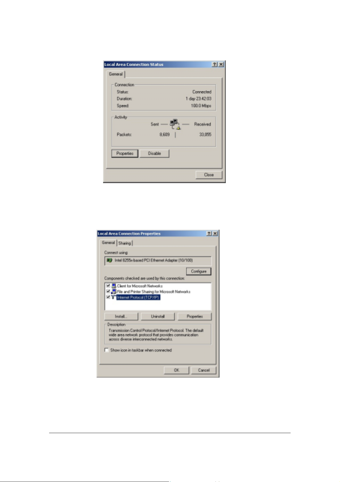
2. Click Properties.
Figure 1. ISP Connection Status Dialog Box
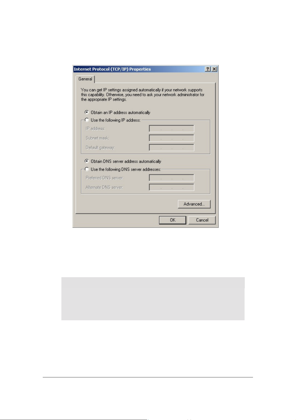
A Properties dialog box will appear:
Figure 2. ISP Connection Properties Dialog Box
3. Click Internet Protocol (TCP/IP), then click Properties.
5
Page 7
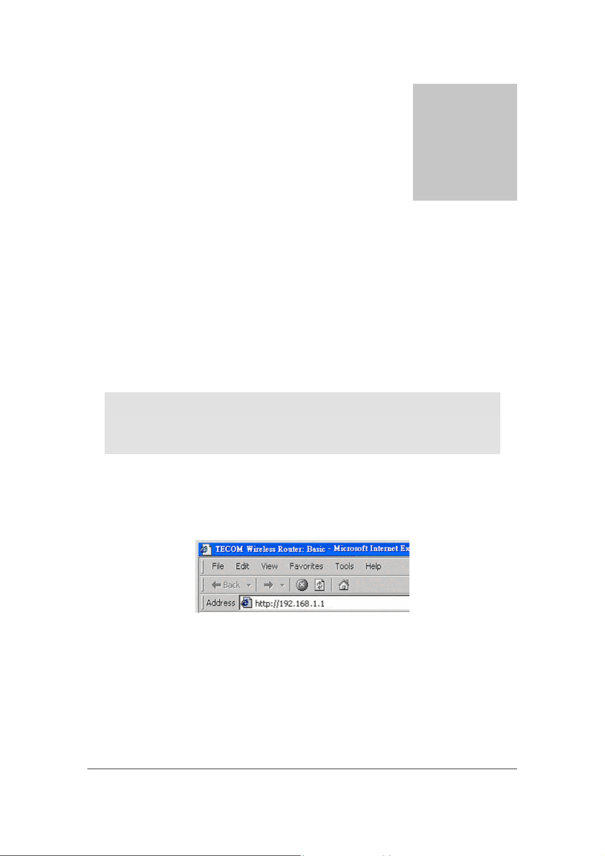
A TCP/IP Properties dialog box will appear:
Figure 3. TCP/IP Properties Dialog Box
4. Click Obtain an IP address automatically and Obtain DNS server address
automatically.
5. Click OK. You may need to restart your computer.
Note
This procedure applies to Windows 2000 operating systems only. For Windows
95/98/ME, Windows NT, or Windows XP, consult your Windows
documentation.
6
Page 8

Collecting ISP Information
You will need to find out some information from your ISP before you can configure your router,
such as:
" Has your ISP assigned you a static IP address, or will they assign one to you dynamically?
If they have given you a static IP, what is it?
" Does your ISP use PPPoE? If so, what is your PPPoE username and password?
Call your ISP if you’re not sure of the answers to these questions.
7
Page 9
Basic Functions
Basic administrative functions include Setup.
he WL5041 Router comes with a web-based tool that you can use to set up and
customize the router settings. You can access this tool from any computer on your
T
network.
Chapter
3
Note
For best results, use Microsoft Internet Explorer version 5.0 or later.
TO OPEN THE WEB-BASED ADMIN TOOL:
1. Open a browser on your PC.
2. Type http://192.168.1.1 in the Address field:
Figure 4. Web Address for Admin Tool
8
Page 10
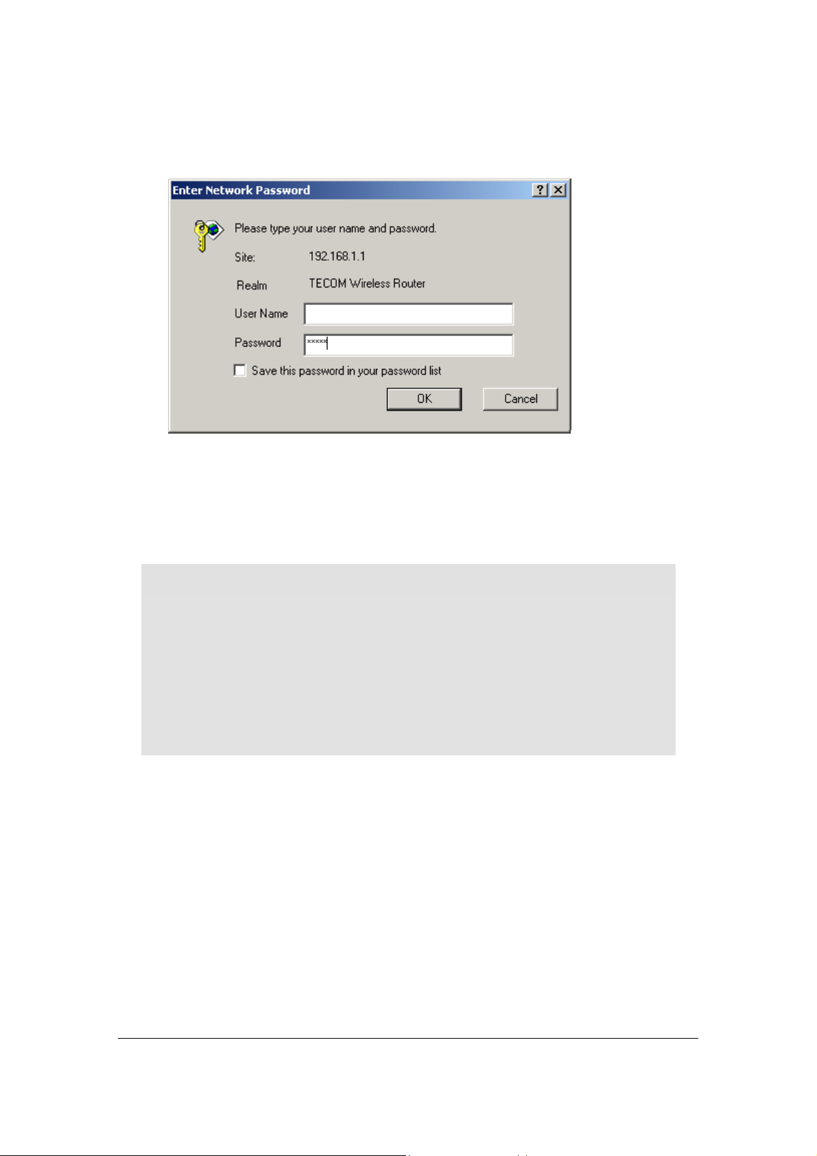
A logon dialog box will appear:
Figure 5. Username/Password Dialog Box
3. Leave User Name field blank. Then, type a Password and click OK. The default
password is admin.
The WL5041 Router Admin Tool will appear.
Note
The web-based Admin Tool will log you out after a certain period of idle time. If
this happens, you will need to re-enter your username and password. If users have
changed default LAN IP Address (192.168.1.1) to someone and forget the IP
address later, you can use the IP alias (192.168.168.1) to en ter the Web configuration
tool. Of course you should make sure that your network device IP address is the
same subnet with 192.168.168.1. For example, ipaddress:192.168.168.5 subnet
mask:255.255.0.0
9
Page 11

Basic
The Basic screen allows you to configure the basic operation of the router.
Although most users will be able to accept the default settings, every Internet Serv ice Provider
(ISP) is different. Check with your ISP if you're not sure which settings they require.
The Basic screen is shown in the figure below.
Figure 6. Basic Screen
10
Page 12

Note
The graphics shown in this manual may differ slightly from your router’s screens.
The images that appear here are provided as examples only.
TO CONFIGURE SETUP PARAMETERS:
1. LAN MAC Address: Shows the MAC Address (also known as the Ethernet address)
of the LAN interface.
2. Review the LAN IP Address information and change if necessary.
These two fields show the Device IP Address and Subnet Mask as seen by others on
your Local Area Network (LAN). Most users will not need to change these values (default
IP is 192.168.1.1, subnet mask is 255.255.255.0).
Note
If you change the LAN IP Address with the DHCP server running, you'll need
to restart your client machines. If you change the LAN IP Address without the
DHCP server running, you'll need to manually reconfigure your clients' IP
addresses.
3. LAN DHCP Server: DHCP is Eabled by factory default. If you have already a
DHCP Server in your network, or you don’t want a DHCP Server, then please select
the Disabled radio button.
Note
If you don’t enable DHCP on your router, you’ll need to manually configure an IP
address for each computer on your network.
4. Setup the LAN DHCP Starting IP Address and Ending IP Address.
I. Make sure there is not already a DHCP server runnin g on your network.
II. Make sure that each computer on your network is configured to receive an IP
address automatically.
III. On the DHCP screen, click Enable.
IV. Type the LAN DHCP Starting IP Address. The address you specify will be the
first IP address that can be assigned to a computer on the network.
11
Page 13

V. Type the LAN DHCP Ending IP Address. The address you specify will be the
last IP address that can be assigned.
VI. Type the LAN Lease Time. Set the number of seconds DHCP leases should be
valid for. The default value is 86400, which means one day.
Example
If you choose 192.168.1.51 as the starting address and 192.168.1.100 as the
ending address, the DHCP server will assign addresses to network clients that
are between 192.168.1 .51 a nd 192. 168. 1.100.
5. LAN Spanning Tree Protocol: Enables the use of the Ethernet 802.1d Spanning
Tree Protocol to eliminate bridging loops across the LAN interfaces.
WAN Setting:
The second part of the Basic screen is the configuration of WAN. The figure is as the
following.
Figure 7. Basic Screen (2)
1. WAN Host Name: Some ISPs require that a host name be provided when requesting an IP
address through DHCP Server. You may have to check with your ISP to see if your
broadband Internet service has been configured with a host name. In most case, leaving the
field blank will work.
2. WAN Domain Name: Set the domain name to be provided to LAN clients who request an
IP address through DHCP Server. You may have to check with your ISP to see if your
broadband Internet service has been configured with a domain name. In most case, leaving
the field blank will work.
3. WAN MAC Address: Some ISPs need that a specific MAC address be used. This field
allows you to set the MAC address of the WAN interface.
12
Page 14

Warning
Please don’t change the default WAN MAC Address unless your ISP request you to
do this action.
4. WAN IP Address: Set the IP address of the WAN in terface.
5. WAN Subnet Mask: Set the IP subnet mask of the WAN interface.
6. WAN Default Gateway: Set the IP address of the default gateway on the WAN.
7. WAN DNS Servers: The DNS (Domain Name System) is how the Internet translates
domain or website names into Internet address or URLs. Your ISP will provide you with at
least one DNS Server IP address. If you wish to use another one, type that IP address in one
of these fields. You can type up to three DNS Server IP address here. The Router will use
these for quicker access to functioning DNS servers.
8. WAN WINS Servers: The Windows Internet Naming Service (WINS) manages each PC’s
interaction with the Internet. If you use a WINS Server, enter that server’s IP address here.
Otherwise, leave this blank.
9. WAN Protocol: Set the method to use to obtain an IP address for the WAN interface.
PPPoE and Routing Setting:
PPPoE (Point-to-Point Protocol over Ethernet) is a protocol used by many ADSL Internet
Service Providers. WL5041 has a free client for Linux, NetBSD and Solaris systems to connect to
PPPoE service providers. The setting screen is shown as the figure below.
Figure 8. Basic Screen (3)
1. PPPoE Username: Set the username to use when authenticating with a PPPoE server.
2. PPPoE Password: Set the password to use when authenticating with a PPPoE server.
13
Page 15

3. PPPoE Keep Alive: If this function is enabled, the PPPoE link should be automatically
restored when the connection is disconnected. This setting has no effect if PPPoE
Connect on Demand is Enable.
4. PPPoE Connect on Demand: If this function is enabled, the PPPoE link should be
automatically disconnected when no traffic has been observed for the period specified by
PPPoE Max Idle Time.
5. PPPoE Max Idle Time: Set the number of seconds to wait before disconnecting the
PPPoE link if PPPoE Connect on Demand is Enable.
6. PPPoE MRU: Set the maximum number of bytes that the PPPoE interface will receive
in a single Ethernet frame.PPPoE MTU: Set the maximum number of bytes that the
PPPoE interface will transmit in a single Ethernet frame. Make sure the value is 1400 or
smaller than 1400. Router Username: Set the username for access to these
configuration pages. Leave this field and Router Password blank to disable access
control.Router Password: Set the password for access to these configuration pages.
Leave this field and Router Username blank to disable access control.Router WAN
Port: Set the WAN port to use the remote access to these configuration pages. Leave
this field blank to disable remote access.Router Mode: Router Mode is default. If you
select Access Point Mode that is disabling LAN DHCP Server, LAN Spanning Tree
Protocol, and WAN Protocol. Firewall: Connections from the WAN are allowed if
the Firewall is disabled.Note
If your ISP has provided the DHCP functionality, you should select the Router
Mode. The capability of Access Point Mode is similar to the single Hub, and
doesn’t support the DHCP function.
The other relevant setting:
Figure 9. Basic Screen (4)
1. Time Zone: Set the Time Zone of this locale.
2. NTP Server: Set the IP address of the NTP Server to use for time synchronization.
3. Syslog IP Address: System log message will be sent to this IP address.
4. UPnP: Set whether Universal Plug and Play (UPnP) is enabled.
14
Page 16

5. Connection Logging: Set which connection through the router should be logged. Selecting
Denied enables logging of denied connections. Selecting Accepted enables logging of
accepted connections. Select Both enables logging of both denied and ac cepted connections.
15
Page 17

Status
The Status screen is a read-only display that gives you information about your router. The data
displayed may change depending on your current configuration.
The Status screen is shown in the figure below.
Figure 10. Status Screen
The displayed data may include:
! Local Time: Showing the local time as kept by the router.
! Connection Log: Showing a log of recent connection attempted.
! Active DHCP Leases: You can view the list of PCs that are given IP address by the router.
For each PC, the list shows the hostname, IP address, MAC address and the amount of
DHCP client lease time left.
16
Page 18

Filters
If no filters are
enabled, all traffic
will be blocked.
Warning
Overwriting the factory default filters may result in your network clients not being
able to access the Internet. When you define new filters, we recommend that you
choose an empty row.
The Filters screen is shown in the figure below.
Use the Filters screen to create and apply filters that can selectively allow
traffic to pass in and out of your network.
Figure 11. Filter Screen (1)
1. LAN MAC Filter Mode: Select whether clients with the specified MAC address are allowed
or denied access to the router.
2. LAN MAC Filters: Filter packets from LAN machines with the specified MAC addresses.
17
Page 19

Figure 12. Filter Screen (2)
3. LAN Client Filters: Filter packets from IP address destined to certain port ranges during the
specified time.
18
Page 20

Routing
Routing is the act of moving information across an Internet from a source to a destination. Along
the way, at least one intermediate node typically is encountered. Routing is often contrasted with
bridging, which might seem to accomplish precisely the same thing to the casual observer. The
primary difference between these two are bridging occurs at Layer 2 (the link layer) of the OSI
reference model, whereas routing occurs at Layer 3 (the network layer). This distinction provides
routing and bridging with different information to use in the process of moving information from
source to destination, so these two functions accomplish their tasks in different ways. The
Routing screen is shown in the figure be low.
Figure 13. Routing Screen (1)
19
Page 21

1. Port Forwards: Forward packets destin ed to ports in the first range t o the LAN machine
with the specified IP address. You may optionally specify a second range. (The range should
not overlap the first range.)
Figure 14. Routing Scree n (2)
2. Application Specific Port Forwards: Automatically forward connections. The function is
used for special applications whose outbound ports differ from the inbound ports. For this
feature, the router will watch outbound data for specific port numbers. The router will
remember the IP address of t he computer t hat sends a transmission requesting data, so that
when the requested data returns through the router, the data is pulled back to the proper
computer by way of IP address and port mapping rules.
3. DMZ IP Address: The DMZ feature allows one local user to be exposed to the Internet for
use of a special-purpose service such as Internet gaming or video conferencing. DMZ
forwards all the ports at the same time to one PC. The Port Forwarding feature is more
secure because it only opens the ports you want to have opened, while DMZ hosting opens
all the ports of one computer, exposing the computer so the In ternet can see it.
20
Page 22

4. Static Routes: A static route is a pre-defined pathway that network information must travel
to reach a specific host or network. To setup a static route between the router and another
network, follow these instructions:
(1) Enter the following data:
! IP address -- The IP address is the address of the network or host to which you
want to assign a static route.
! Subnet Mask – The Subnet Mask determines which portion of a destination IP
address is the network portion, and which portion is the host portion.
! Gateway – This is the IP address of the gateway device th at allows for contact
between the router and the network or host.
(2) Depending on where the destination IP address is located, select LAN or WAN from
the interface drop-down menu.
(3) To save your changes, click the Apply button. To cancel your changes, click the Cancel
button.
21
Page 23

Wir e le s s
Use the Wireless screen to configure your router for wireless access.
The Wireless screen is shown in the figure below.
Figure 15. Wireless Screen (1)
22
Page 24

1. Wireless Interface: Select which wireless interface to configure.
2. Network Name (SSID): This field is the network name shared among all devices in a
wireless network. The SSID must be identical for all devices in the wireless network. It is
case-sensitive and must not exceed 32 alphanumeric characters, which may be any keyboard
character. Make sure this setting is the same for all device s in your wireless network.
3. Network Type: When wireless clients survey the local area for wireless networks to associate
with, they will detect the SSID bro adcast by the router. To broad cast the r outer’ s SSID, ke ep
the default value Open. If you do not want to broadcast the router’s SSID, then select
Closed.
4. Country: Restrict the channel set based on country requirements.
5. Radio: To Enable or disable the wireless radio.
6. Band: Select the wireless radio band to use.
7. Channel: Select the appropriate channel from the list provided to correspond with your
network settings. All devices in your wireless network must use the same channel in order to
function correctly.
8. 54g Mode: Select the mode to 54g A uto for the widest compatibility. Select the mode to 54g
Performance for the fastest performance among 54g certified equipment. Set the mode to
54g LRS if you are experiencing difficulty with legacy 802.11b equipment.
9. 54g protection: In Auto mode the router will use RTS/CTS to improve 802.11g
performance in mixed 802.11g/802.11b networks. Turn protection off to maximize 802.11g
throughput under most conditions.
10. Rate: The default setting is Auto. The range is from 1 to 54Mbps. The rate of data
transmission should be set depending on the speed of your wireless network. You can select
from one transmission speed, or keep the default setting, Auto, to have the router
automatically use the fastest possible data rate.
11. Basic Rate Set: Select the basic rate that wireless clients must support.
12. Fragmentation: This value should remain at its default setting of 2346. The range is 256-
2346 bytes. It specifies the maximum size for a packet before data is fragmented into multiple
packets. If you experience a high packet error rate, you may slightly increase the
Fragmentation. Setting the Fragmentation too low may result in poor network performance.
Only minor modifications of this value are recommended.
13. RTS Threshold: This value should remain at its default setting of 2347. The range is 0-2347
bytes. Should you encounter inconsistent data flow, only minor modifications are
recommended. If a network packet is smaller than the preset RTS threshold size, the
RTS/CTS mechanism will not be enabled. The router sends Request to Send (RTS) frames to
a particular receiving station and negotiates the sending of a data frame. After receiving an
RTS, the wirele ss sta tion re sp ond s w ith a Clea r to S en d ( CT S) fra m e to a ckn o wle dg e the righ t
to begin transmission.
23
Page 25

14. DTIM Interval: The default value is 3. This value, be tween 1 and 255 milliseconds, indicates
the interval of the Delivery Traffic Indication Message (DTIM). A DTIM field is a
countdown field informing clients of the next window for listening to broadcast and multicast
messages. When the router has buffered broadcast or multicast for associated clients, it sends
the next DTIM with a DTIM Interval value. Its clients hear the beacons and awaken to
receive the broadcast and multicast me ssage.
15. Beacon Interval: The default value is 100. Enter a value between 1 and 65535 milliseconds
The Beacon Interval value indicates the frequency interval of the beacon. A beacon is a packet
broadcast by the router to synchronize the wireless network.
16. Preamble Type: Set whether short or long preambles are used. Short preambles improve
throughput but all clients in the wireles s netw ork must support this capabili ty if selec ted.
Figure 16. Wireless Screen (2)
17. AP Mode: Selecting Wireless Bridge disables access point functionality. Only wireless
bridge (also known as Wireless Distribution System or WDS) functionality will be available.
Selecting Access Point enables access point functionality. Wireless bridge functionality will
still be available and wireless stations will be able to associate to the AP.
18. Bridge Restrict: Selecting Disabled disables wireless bridge restriction. Any wireless bridge
(including the ones listed in Remote Bridges) will be granted access. Selecting Enabled
enables wireless bridge restriction. Only those bridges listed in Remote Bridges will be granted
access.
19. Remote Bridges: Enter the wireless MAC addresses of any remote bridges that should be
part of the wireless distribution system (WDS)
20. MAC Restrict Mode: Select the clients with the specified MAC address are allowed or
denied wireless access
21. MAC Addresses: To allow or deny wireless access for clients with the specified MAC
addresses. Leave all entries blank to allow access for any client
24
Page 26

Security
Figure 17. Security Screen
25
Page 27

1. Wireless Interface: Select which wireless interface to configure.
2. Network Authentication: Set the network authentication method. 802.1X and WPA require
setting valid RADIUS parameters. WPA-PSK requires a valid WPA Pre-Shared Key to be
set.
! 802.1X: As the IEEE standard for access control for wireless and wired LANs, 802.1x
provides a means of authenticating and authorizing devices to attach to a LAN port.
This standard defines the Extensible Authentication Protocol (EAP), which uses a
central authentication server to authenticate each user on the network
.
! WPA: The Wi-Fi Alliance put together WPA as a data encryption method for 802.11
wireless LANs. WPA is an industry-supported , pre -standard version of 802.11i uti lizing
the Temporal Key Integrity Protocol (TKIP), which fixes the problems of WEP,
including using dynamic keys.
3. WPA Pre-Shared Key: Set the WPA Pre-Shared Key (PSK).
4. WPA Group Rekey Interval: Set the WPA Group Rekey Interval in seconds. Leave blank
or set to zero to disable p eriod ic re keying.
5. RADIUS Server: Set the IP address of the RADIUS server to use for authentication and
dynamic key derivation.
! RADIUS Server: A server that is responsible for receiving user connection requests,
authenticating the user, and then returning all of the configu ration information necessary
for the client to deliver the service to the user.
6. RADIUS Port: Set the UDP port number of the RADIUS server. The port number is
usually at 1812 or 1645 depending on the server.
7. RADIUS Key: Set the shared secret for the RADIUS connection.
8. Data Encryption (WEP): Selecting Off disables WEP data encryption. Selecting WEP
enables WEP data encryption and requires that a valid network key be set and selected unless
802.1X is enabled.
! WEP: WEP, short for Wired Equivalent Privacy, is a protocol for wireless LANs or
local area networks. This WEP is defined in the 802.11 Standard. WEP is designed so
security levels are maintained at the same level as the wired LAN. WEP's aim is to
provide security by encrypting data over radio waves. WEP protects data as it's
transmitted from one end point to another. WEP is used at the two lowest layers, the
data link and physical layer. WEP is designed to make up for the inherent security in
wireless transmission as compared to wired transmission.
9. Shared Key Authentication: Set whether shared key authentication is required to associate.
A valid network key must be set and selected if required.
26
Page 28

10. Network Key 1-4: Enter 5 ASCII characters or 10 hexadecimal digits for a 64-bit key. Enter
13 ASCII characters or 26 hexadecimal digits for a 128-bit key.
11. Current Network Key: Select which network key is used for encrypting outbound data
and/or authe ntic ati ng c lien ts.
Note
Although 128 Bit encryption uses a more secure encryption algorithm, it can
slow down your network’s data transmission rates.
27
Page 29

Firmware
You can use this page to download the firmware as the following.
1. Firmware Version: Displays the current version of Firmware.
2. New Firmware: Selects the new firmware to upload to the router. The following steps will
tell you how to upgrade.
A. Download a firmware image file from the router website and save it to your hard
drive. Make sure to write down the file location.
B. Type the filename and path location d irectly into the New Firmware field, or click
Browse… to launch the Choose file dialog box:
Figure 18. Firmware Screen
28
Page 30

Figure 19. Choose File Dialog Box for Firmware Upgrade
C. Locate the firmware you downloaded and click Open.
Click Upgrade. The firmware of the device will be upgraded.
Warning
Upgrading the firmware takes several seconds. Don’t power down the router
while the firmware upgrade operation is in progress.
29
Page 31

T echnical Support
If you are still experiencing problems after reading Product User’s Guide,
you may either contact our technical support at: support@tecom.com.tw
OR, simply click our URL address www.tecomproduct.com
company website and check the latest version and other information about
the product and/or software.
to go to our
.
Reset to Default
This device has a reset button that can return to the original setting. You can
find this button in the rear panel of the device. The reset steps are shown as
below:
1. Power off the device.
2. Press the reset button.
3. While pressing the reset button, Power on the device. Keep the button
pressed for at least 3 seconds
4. Release button.
Troubleshooting
When you use the web tool to configure the AP/Router, an error message “Link Error”
appear. Please check your IE version. If the version number is "5.00.3315.xxxx”, please
upgrade your IE to solve this exception.
IE 5.5 SP2 download site:
http://www.microsoft.com/windows/ie/downloads/recommended/ie55sp2/default.asp
IE 6.0 SP1 download site:
http://www.microsoft.com/windows/ie/downloads/critical/ie6sp1/default.asp
30
Page 32

Wireless LAN 802.11g Router
Product Name Wireless LAN 802.11g Router
Model Number WL5041
Host Interface 1 WAN port, 4 LAN port
Power Adaptor
AC 100 ~ 240V, 0.35A
Input
Input Power DC 5V, 2.5A
Modulation 802.11b : CCK, DQPSK, DBPSK
802.11g : OFDM
Data rate CCK – 11, 5.5 Mbps
DQPSK – 2 Mbps
DBPSK – 1 Mbps
OFDM – 54, 48, 36, 24, 18, 12, 9, and 6 Mbps
Output Power Typical: 15 dBm, maximal : 18dBm
Security 64-bit and 128-bit WEP Encryption
LED indicator Power, LAN Link/Act, WAN Link/Act, WLAN
Link/Act, Diag
Standards IEEE 802.11b and 802.11g compliant for wireless
LAN, IEEE 802.3 for wired LAN
Temperature
Range
! 0 ~ 55°C (Operating)
! -20~65°C (Storing)
Humidity Max. 90% Non-condensing
Operating Range
! Open Space: 100 – 300m
! Indoor: 30m – 100m
The transmission speed varies in the surrounding
environment.
Network Protocol TCP/IP, IPX, NetBEUI
Physical
! 150mmx107mmx34mm
Dimension
Certifications FCC Class B, CE Mark
31
 Loading...