

Page 1
Copyright © All Rights Reserved, 2010
M/C: TSIP-2092B-G-UM
DC: 991202A-1
WEB IP PHONE
User Manual
ISO-9001ISO-9001
Page 2

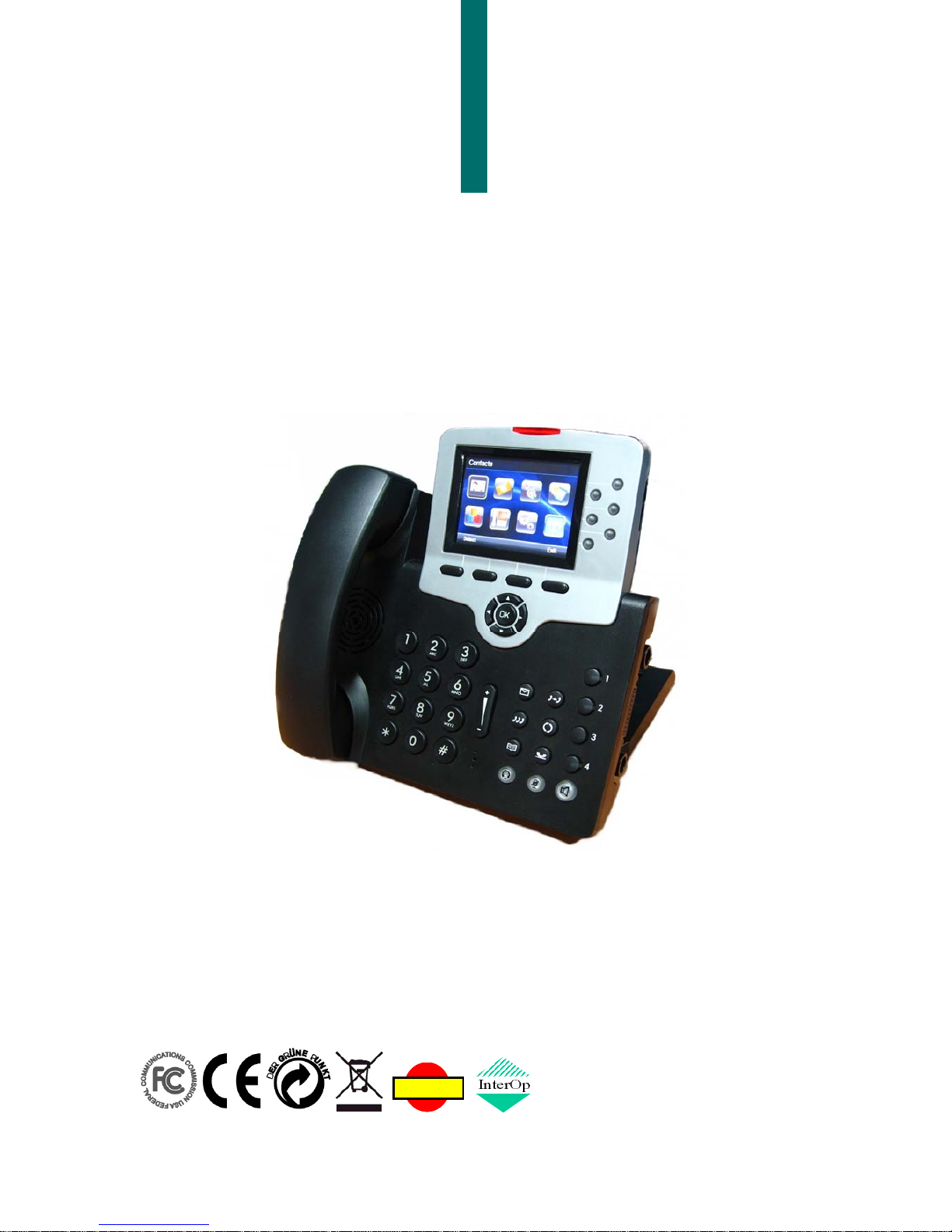
WEB IP PHONE - USER MANUAL
2
Environment
The phone you have purchased must not be disposed of with househo ld w aste. You should
return these to your distributor if they are to replace or dispose of them in an approved
recycling centre.
FCC Statement
This equipment has been tested and found to comply with the limits for a Class B digital
device, pursuant to part 15 of the FCC Rules. These limits are designed to provide
reasonable protection against harmful interference in a residential installation. This
equipment generates, uses and can ra diate ra dio frequency en ergy and, if not insta lled and
used in accordance with the instructions, may cause harmful interference to radio
communications. However, there is no guarantee that interference will not occur in a
particular installation. If this equipment does cause harmful interference to radio or
television reception, w hich ca n be det ermined by turning the equ ipm ent of f and on , the use r
is encouraged to try to correct the interference by one or more of the following measures:
Reorient or relocate the receiving antenna.
Increase the separation between the equipment and receiver.
Connect the equipment into an outlet on a circuit different from that to which the
receiver is connected.
Consult the dealer or an experienced radio/TV technician for help.
CE Declaration of Conformity
This equipment complies with the requirements relating to electromagnetic compatibility,
EN55022 class B for ITE and EN 50082-1. This meets the essential protection
requirements of the European Council Directive 89/336/EEC on the approximation of the
laws of the Member States relating to electromagnetic compatibility.
Copyright Notice
All rights reserved. No part of this publication may be reproduced, transmitted, transcribed,
stored in retrieval system or translated in to any language or computer language, in any
from or by any means, electronic, mechanical, magnetic, optical, chemical, manual or
otherwise, without the prior written permission of Company.
Company reserv es the r ight to revise the public ation an d make changes from tim e to t im e in
the contents hereof without obligation of this company to notify person of such revision or
changes. The material contained herein is supplied without representation or warranty of
any kind. The Company therefore assumes no responsibility and shall have no liability of
any kind arising from the supply or use of this document or the material contained herein.
Trademarks
All trade names and trademarks are the properties of their respective companies.
Page 3

WEB IP PHONE - USER MANUAL
3
WARNING!
1. Read these installation instructions carefully before connecting the Web IP Phone to its
power source.
2. To reduce the risk of electric shock, do not remove the cover from the Web IP Phone or
attempt to dismantle it. Opening or removing covers may expose you to dangerous
voltage levels. Equa lly, incorrect r eassembly could cause electric sh ock on re-us e of th e
appliance.
3. Do not expose the Web IP Phone to fire, direct sunlight or excessive heat.
4. Do not expose the Web IP Phone to rain or moisture and do not allow it to come into
contact with water.
5. Do not install the Web IP Phone in an environment likely to present a THREAT OF
IMPACT.
6. You may clean the Web IP Phone using a fine damp cloth. Never use solvents (such as
trichloroethylene or acetone), which may damage the phone’s plastic surface and LCD
screen. Never spray the phone with any cleaning product whatsoever.
7. Take care not to scratch the LCD screen.
8. The Web IP Phone is designed to work in temperatures from 5oC to 45oC.
9. The Web IP Phone must be installed at least 1 meter from radio frequency equipment,
such as TVs, radios, hi-fi or video equipment (which radiate electromagnetic fields).
10. Do not connect the LAN/PC port to any network other than an Ethernet network.
11. Do not attempt to upgrade your Web IP Phone in an unstable power environment. This
could cause unexpected issues.
12. Do not work on the system or connect or disconnect cables during lightning storms.
13. Children don't recognize the risks of electrical appliances. Therefore use or keep the
phone only under supervision of adults or out of the reach from children.
14. No repair can by performed by the end user, if you experience trouble with this
equipment, for repair or warranty information, please contact your supplier.
Electrical Powering:
The Web IP P hone m ust be pow ered using a cor rect power ad aptor . Any damage caused
to the Web IP Phone as a result of using unsupported power adaptors will NOT be covered
by the manufacturer’s warranty.
COMPANY disclaims all responsibility in the event of use that does not comply with the
present instructions.
Product Disposal Warning:
Ultimate disposal of this product, accessories and packing, should be handled carefully for
recycle and nature protection in accordance with national laws and regulations.
!
Page 4

WEB IP PHONE - USER MANUAL
4
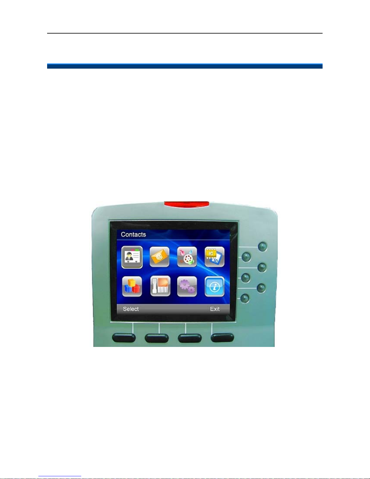
1. Contents
1. Contents......................................................................................................................4
2. Getting Started ............................................................................................................6
Package Contents........................................................................................................7
Installing the Foot Stand Kit..........................................................................................7
Connecting the handset and optional headset..............................................................8
Connecting network and power source.........................................................................9
3. Overview of the Web IP Phone ................................................................................10
The Front View of the Web IP Phone..........................................................................10
Understanding the Front Panel Indicators..................................................................12
LCD Screen Indicators................................................................................................13
The Side and the Rear View of the Web IP Phone..................................................... 15
4. Customizing the Web IP Phone...............................................................................16
Changing the Display Contrast and Brightness..........................................................17
Changing the Display Wallpaper.................................................................................17
Adjusting the Web IP Phone Volume.......................................................................... 19
Managing Contacts.....................................................................................................20
5. Using the Basic Features of the Web IP Phone .....................................................24
Basic Call Operations.................................................................................................24
Making calls.........................................................................................................24
Making calls (direct IP address calling)................................................................24
Answering calls....................................................................................................25
Redialing numbers...............................................................................................25
Muting the microphone........................................................................................25
Adjusting the voice volume during a conversation...............................................26
Advanced Call Operations..........................................................................................26
Placing calls on hold............................................................................................26
Transferring calls (Blind transfer).........................................................................26
Transferring calls (Attended transfer) ..................................................................27
Making 3-way conference calls............................................................................27
Access Voice Mail.......................................................................................................28
Listening to voice messages................................................................................28
Speed-D ia l Function...................................................................................................28
Assigning speed dial key.....................................................................................28
Dialing a speed dial index....................................................................................29
Call-Block Function.....................................................................................................29
Page 5

WEB IP PHONE - USER MANUAL
5
Assigning call blocking numbers..........................................................................29
Basic Call Features.....................................................................................................30
Don’t disturb........................................................................................................30
Auto answer.........................................................................................................30
Call waiting..........................................................................................................30
Call completion....................................................................................................31
Call forwarding.....................................................................................................31
Phone Lock.................................................................................................................32
Locking phone.....................................................................................................32
Information about the Web IP Phone..........................................................................32
View information about the Web IP Phone..........................................................32
On-phone Help for Basic Phone Operations...............................................................33
Look up help page about basic phone operation.................................................33
6. Using the Advanced Features of the Web IP Phone..............................................34
Messaging Functions..................................................................................................34
Multimedia Functions..................................................................................................35
File Browser................................................................................................................37
Applications................................................................................................................38
On-Condition Function................................................................................................41
Programmable Keys...................................................................................................42
XML Web Services.....................................................................................................47
7. Web Configuration....................................................................................................48
Login page..................................................................................................................48
Information..................................................................................................................49
Phone - Basic Functions.............................................................................................50
Phone - Advanced Functions......................................................................................52
Phone - On Conditions ...............................................................................................55
Phone - Key Settings..................................................................................................56
System Setting............................................................................................................58
Contacts - Private Phonebook....................................................................................59
Contacts - Public Phonebook.....................................................................................59
EDM Setting ...............................................................................................................60
8. Troubleshooting........................................................................................................61
9. Appendices...............................................................................................................62
Appendix A: On Condition Template Profile ...............................................................62
Appendix B: On Condition Table Action Configuration Profile....................................63
Page 6

WEB IP PHONE - USER MANUAL
6
2. Getting Starte d
The Web IP Phone is an Internet Telephony desktop phone that connects to an Ethernet
network rather than a tra d itiona l PSTN li ne. Basical ly, it can be us ed as an ex tension phone
in an office or stand alone phone at home. In general, it shall be registered to an IP PBX,
SIP Server or ISP/ITSP Soft Switch and can deliver good voice quality and perform a great
number of multimedia versatile function and PBX-equivalent call features.
After it is deployed and connected among headquarter and remote branch offices all over
the world, it can make, receive and transfer voice over the free IP network. All of them are
stand-alone and “always-on” terminals so that there is no need to have any active PC to let
it work. With optional capability, this phone can perform instant message, e-mail,
multi-media function, video streaming surveillance, basic information web browsing, and
XML server application. It will improve the productivity of your work and let you enjoy the
new technology with phones.
Page 7
WEB IP PHONE - USER MANUAL
7
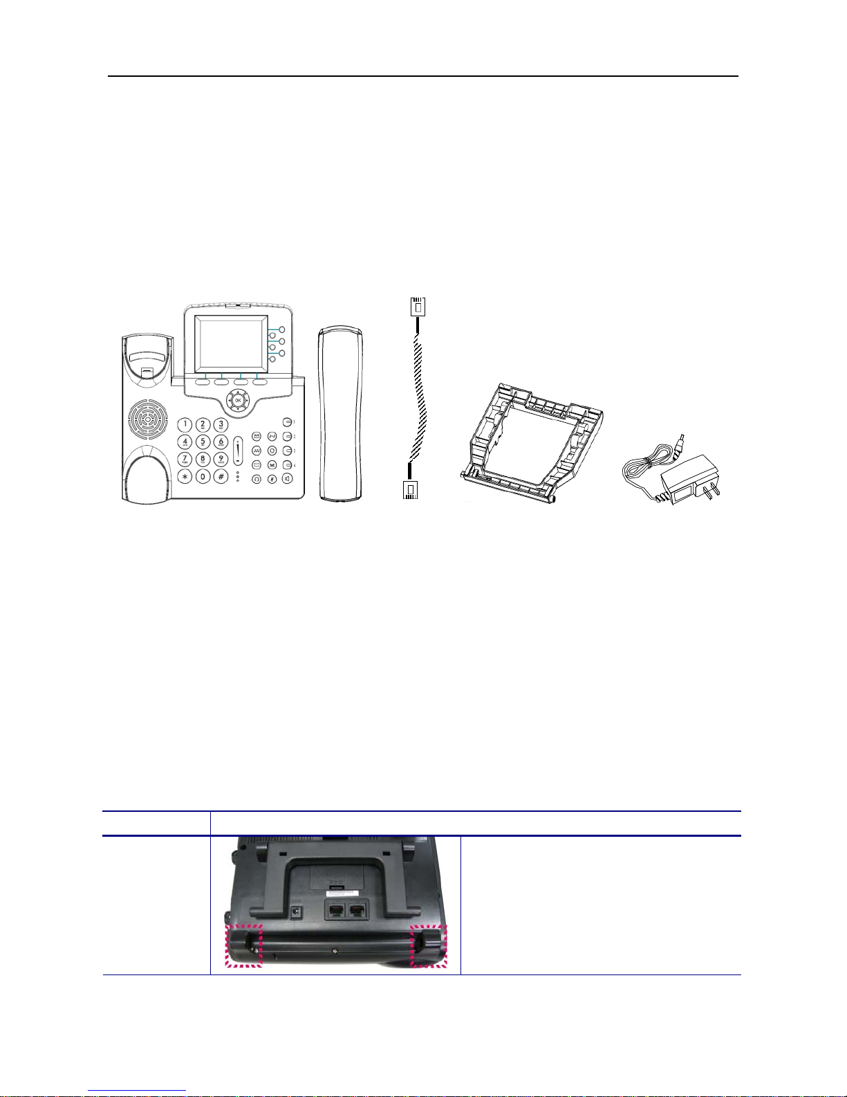
Package Contents
Prior to install the IP Phone, please check the package contents, and make sure that you
have the following items. Be sure that no damage is found on these items, the power
adaptor (optional) and plug type meets the standard of your country and the accessories
are supplied together. If you found any problem with them, please contact the reseller or
supplier for assistance.
The package should include the following items:
1. One main unit of Web IP Phone
2. One handset
3. One handset cord
4. One phone base kit
5. One power adapter (5V/2A, optional)
6. One quick user guide with a warranty card
Installing the Foot Stand Kit
Operation Description
Installing
the phone
base kit
1. Turn the main unit to rear side.
Note that there are two holes to
insert the protrusions of the phone
base.
Main unit Handset Ha ndset Phone base kit Power adapter
cord (optional)
Page 8
WEB IP PHONE - USER MANUAL
8
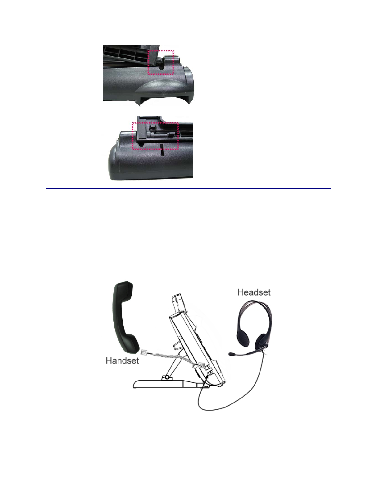
2. Insert the right protrusion of the
phone base into the right hole of
the main unit.
3. Align the left side of the phone base
with the left hole of the main unit. And
then push the left protrusion of the
phone base into the hole of the main
unit. Finally, press the left protrusion
down to lock the phone base to the
phone.
Connecting the handset and optional headset
(1) Connect the handset cord between the handset and the handset jack on the phone.
(2) Connect the headset (optional) on the headset jack of the phone.
Page 9
WEB IP PHONE - USER MANUAL
9
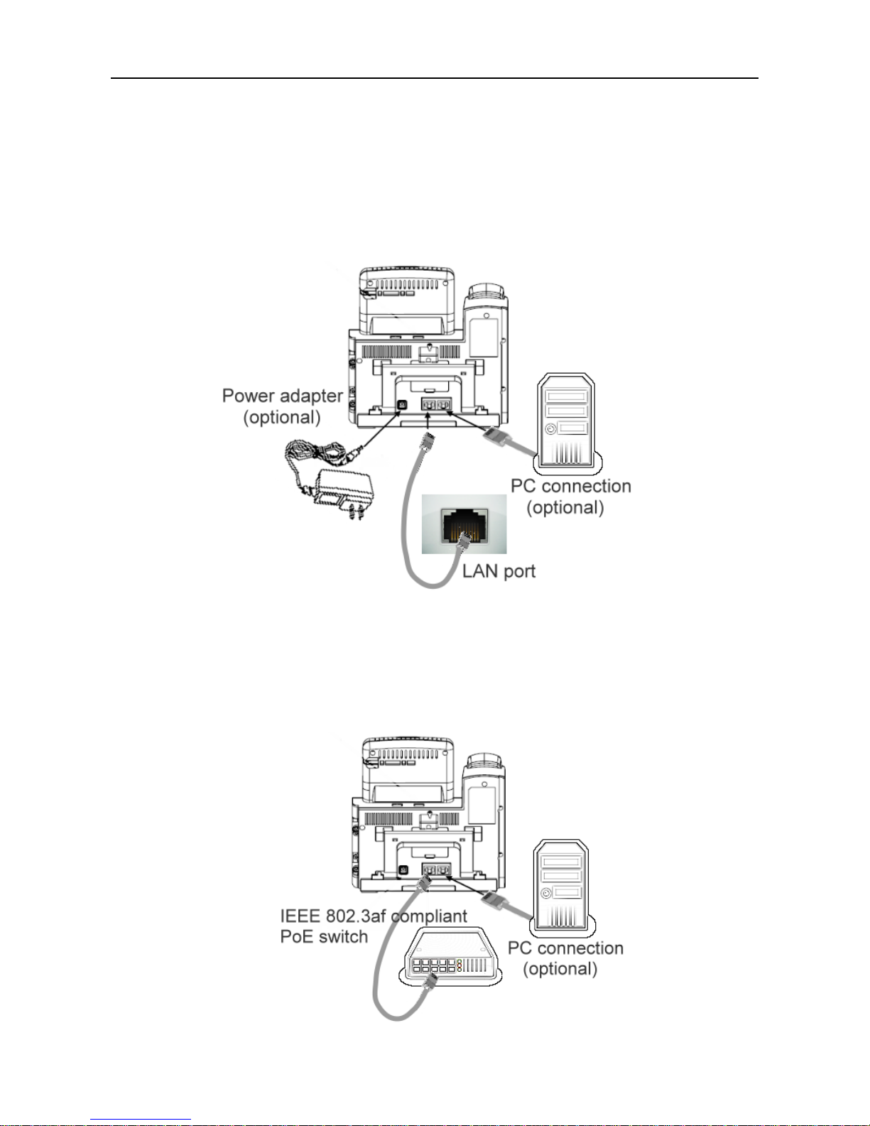
Connecting network and power source
To connect the AC power:
(1) Connect a network cable between the LAN jack on the phone and the LAN port on the
wall or hub/switch device port.
(2) Connect the DC plug on the power adapter to the DC 5V/2A jack marked on the phone.
To connect the PoE:
Connect a network cable (regular CAT5 cable) between the LAN jack on the phone and an
available power and data port on a PoE (IEEE 802.3af) compliant switch.
Page 10
WEB IP PHONE - USER MANUAL
10
3. Overview of the Web IP Phone
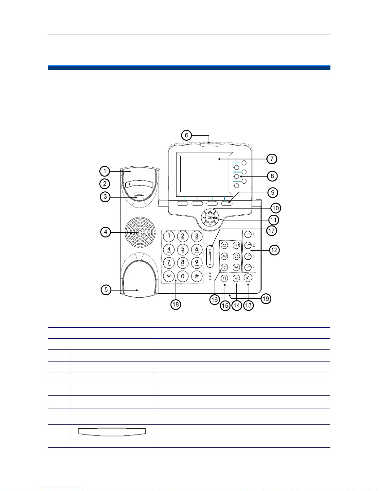
The Front View of the Web IP Phone
The figure be low illustrates the front view of th e We b IP Phone. With the po int numbers, you
can find its name and a simple description of the part in the following table.
No Part Name Description of function
0 Main unit The Web IP Phone main unit.
1 Handset top cradle For the placement of handset (Receiver end).
2 Hook switch For hang-up and hang-off of handset.
3 Cradle latch
To latch the handset from drop when it stands at 60
o
degree
or is wall-mounted.
4 Speaker For ring and ha nds free talking.
5 Handset bottom cradle For the placement of handset (Transmitter end).
6
Message LED
This red LED to indicate status of message waiting and link
status.
Page 11
WEB IP PHONE - USER MANUAL
11
7
Color LCD with
touch panel
The 3.5” color LCD with touch panel is for displaying phone
settings, m ul ti m e di a, XML informati on an d so forth. It supports
320 x 240 pixels.
8
6 line keys
These keys are mainly used for line selection. A green LED is
associated with each key to indicate its line/call status.
Besides, these keys are also used for programming as
different hot keys by setting on menu.
9
Soft keys
The keys are used for item selection or control on the LCD
screen. Each key function depends on its corresponding
content displayed on the LCD at that time.
10
Navigation keys
The keys including four arrows are used for surfing the items
on the LCD scree n.
11
OK key
It is normally used to confirm the setting or phone number
dial.
12
1,2,3,4
Programmable
keys
These keys ar e used for pr ogr am m i n g as differen t hot keys by
setting on menu. A green LED is associated with each key to
indicate its status.
13
SPKR key
This SPKR key is used to activate/de-activate the Hands free
dial or talk. A blue LED is associated to indicate its status.
14
Mute key
This MUTE key is used to activate/de-activate the voice
transmits from this Web IP Phone. A red LED is associated to
indicate its status.
15
Headset key
This Headset key is used to activate/de-activate the Headset.
A green LED is associated to indicate its status.
XFR key
To transfer a call to another IP phone.
Redial key
To redial the last dialed number automatically.
Hold key
To hol d on the curre nt ca ll and get an othe r new to cal l. Once
again, it will release the HOLD function.
16
MSG key
To get access to Voice Mail System for message retrieval.
Page 12
WEB IP PHONE - USER MANUAL
12
CONF key
To drop the current multiple connected phones into a
conference. It is a phone-bridged function.
Contacts key
To enter into the Contacts for call or edit. The LCD screen will
prompt the Contacts once it is pressed.
17
Volume control key
It is used for volume control: When the phone is idle, the ring
is adjusted. When talking, the Handset/Speaker/Headset
output volume is adjusted.
18
[1], [2]…[9], [*], [0], [#]: The numeric keypad for dialing
numbers.
19 Microphone Hole A small hole for Hands-free Microphone input.
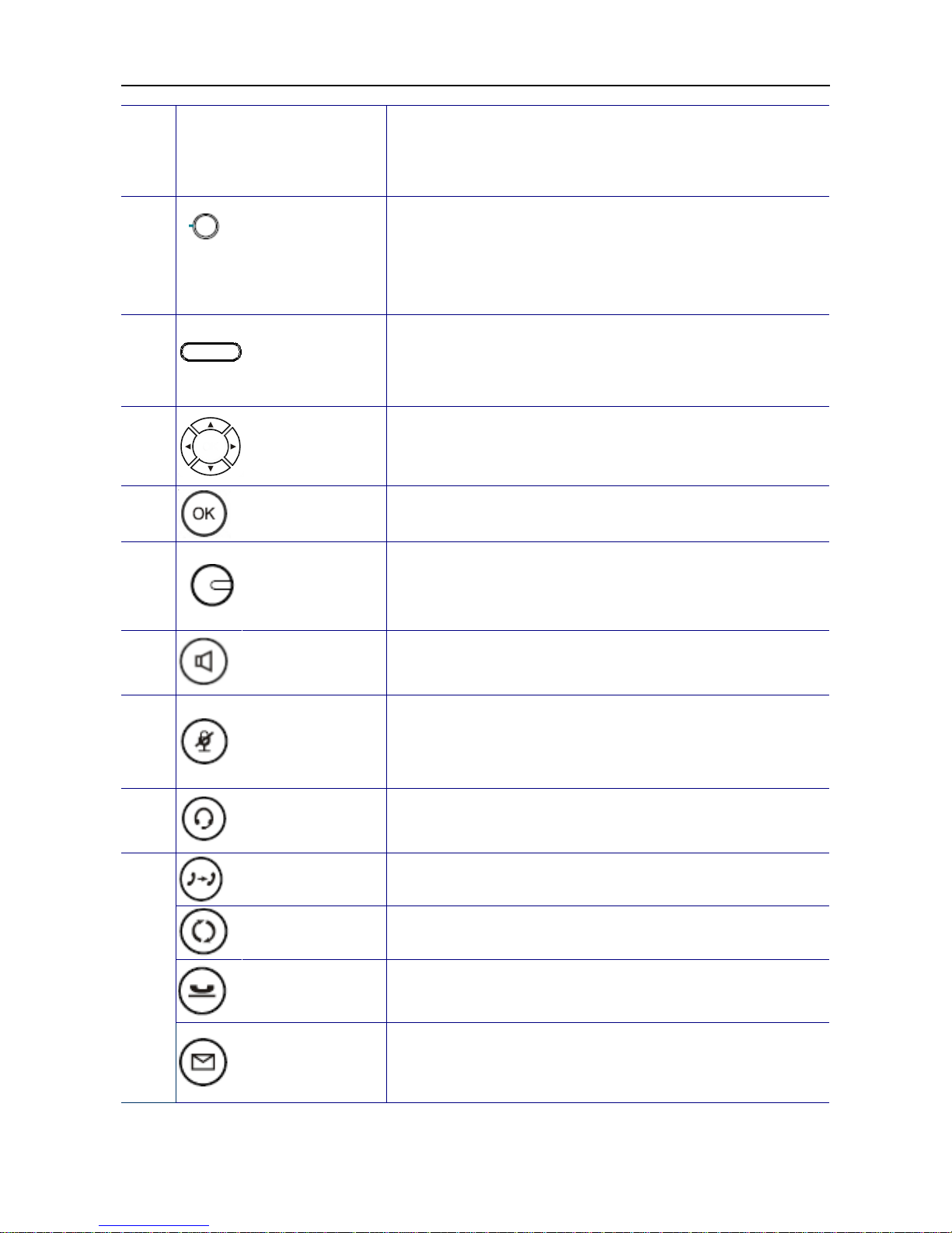
Understanding the Front Panel Indicators
LED Color Status Description
Off No new message.
Steady
Possible meaning:
- Phone is booting.
- Firmware is upgrading.
Blinking slow
New message indication; includes voice mail,
instant message and e-mail. Their respective
icons are als o displayed.
MSG
Red
Blinking fast
Possible meaning:
- Link disconnected.
- Registration failed.
- System fault and phone service is down.
Off
As a line key, it means the line is inactive. The
phone is on-hook.
A
s a pro gram m a bl e key, it m e ans the function
is inactive.
6 VoIP lines keys
Green
Steady
As a line key, it means the line is active
(dialing, or during a call).
A
s a pro gram m a bl e key, it m e ans the function
is enabled.
Page 13
WEB IP PHONE - USER MANUAL
13
Blinking
As a line key, it means the line has an
incoming call or a call on hold.
A
s a pro gram m a bl e key, it m e ans the function
is engaged.
Off No active function.
Steady Function is enabled.
1, 2, 3, 4
Programmable keys
Green
Blinking Func tion is engaged.
Off The speaker is not in use.
SPKR key
Blue
Steady The phone is in hand-free mode.
Off Th e microphone is active.
MUTE key
Red
Steady The microphone is inactive.
Off The headset is not in use.
Headset key
Green
Steady The phone is in headset mode.
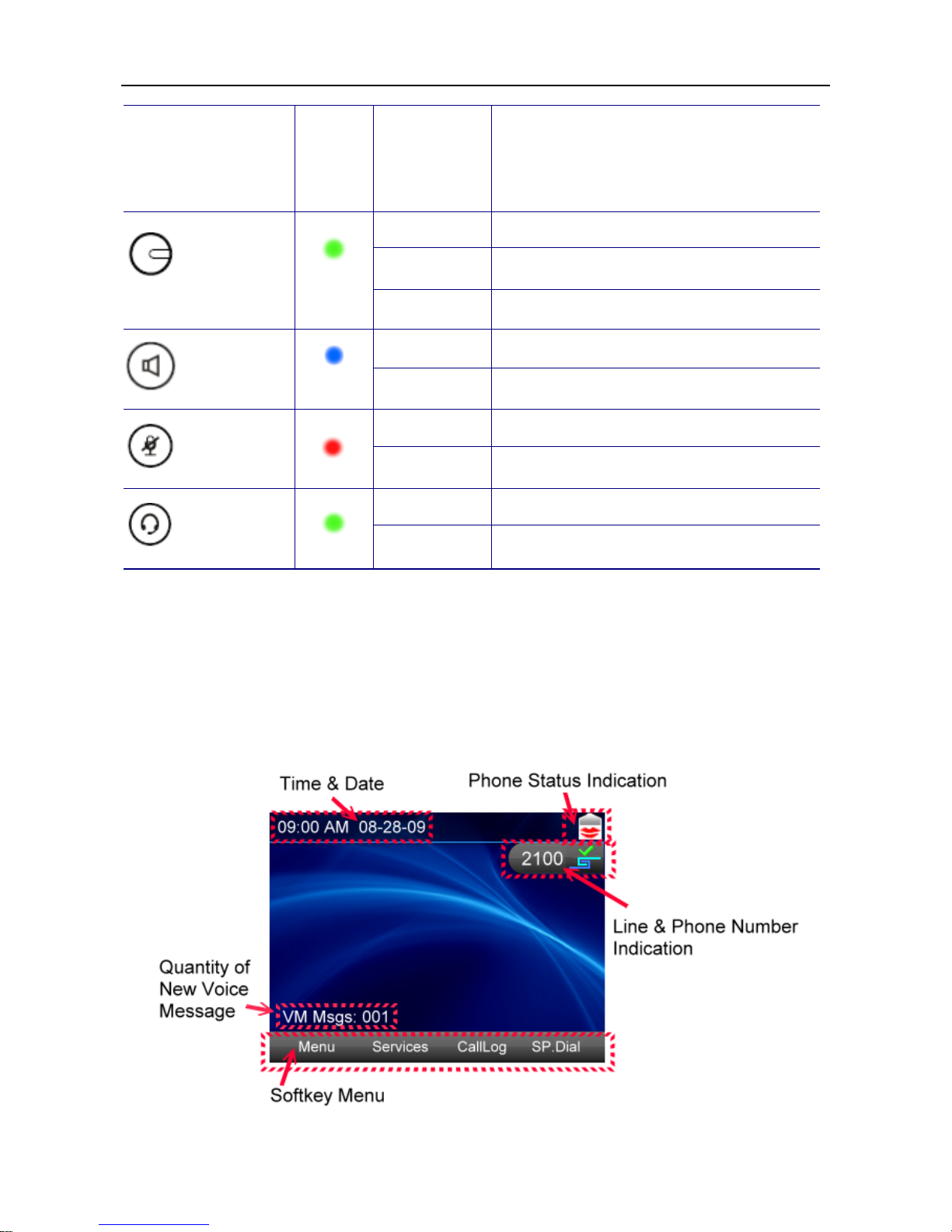
LCD Screen Indicators
The following figure shows a standard format of LCD screen. There are 4 soft keys
associated with the operation of LCD display. For different menu or status, the display
format will be changed accordingly.
Page 14
WEB IP PHONE - USER MANUAL
14
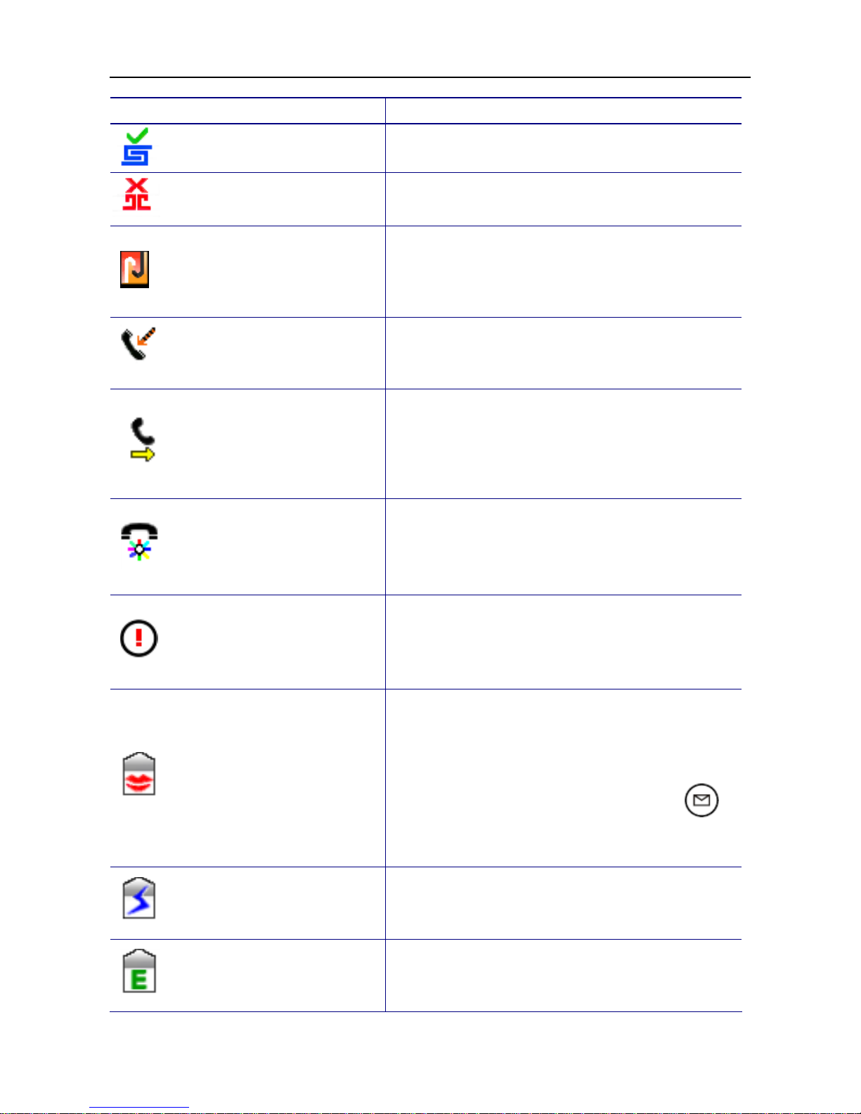
Icon Name Description
Register successful
This icon indicates this line is registered successfully.
Register failed
This icon indicates this line is registered failed.
Network cable disconnected
This icon indicates the network cable is disconnected.
Please check if the network cable is connected to the
Web IP Phone and IP network properl y.
Missed call
This icon indicates you have a new missed call. Please
enter CallLog to see the new missed call.
Call forward
When the Web IP Phone is enabled “Call Forwarding”,
the icon will be displayed. Call forwarding setting
includes 3 options: unconditional forwarding, no
answer forwarding and busy forwarding.
Auto answer
When the Web IP Phon e is en a bl ed “ A uto Answer”, the
icon will be displayed. Any incoming call will be
answered automatically.
Don’t disturb
When the Web IP Phone is enabled “Don’t Disturb”, the
icon will be displayed. You will not hear or see any
incoming call.
Voice mail
When the icon is displayed on the screen of Web IP
Phone, it means you have a new voice mail.
A
lso, you
can see the Q’ty of new voice mail message that is
showed as “VM Msgs: XXX”. Please press
to
access your voice mail for message retrieval.
Instant message
When the icon is displayed on the screen of Web IP
Phone, it means you have a new instant message.
E-mail
When the icon is displayed on the screen of Web IP
Phone, it mea ns you h av e a new e- m ai l .
Page 15

WEB IP PHONE - USER MANUAL
15
Wireless Signal Strength
When the icon is displayed on the screen of Web IP
Phone, it means your Web IP Phone is connected with
Wi-Fi Ethernet bridge*, and its signal strength is good.
Note: For the Wi-Fi Ethernet bridge, please contact
with your distributor for purchasing.
Wireless signal is medium.
Wireless signal is poor.
Wireless signal is disconnected.
The Side and the Rear View of the Web IP Phone
No Part Name Description of function
1
USB connector
(Optional)
This U SB con necto r is used f or co nnect ing w ith a Mini Ke yboa rd
which is for entering characters by typing keys of it. For the Mini
Keyboard, pl e as e conta c t wit h yo ur dis tr i bu tor for purc h as in g.
2 Touch panel pen slot
The Web IP Phone shipped with a touch panel pen is put in this
slot.
3
SD car d slot
(Optional)
This SD card slot is used for inserting a SD card which is for
saving preferable multimedia* in the SD card, and play them on
Web IP Phone. * For formats supported, please contact with your
distributor for details.
4
EDM slot
(Optional)
This EDM slot is used for connecting with a specific extended dial
module which is for pr o gr am m a bl e fe atures. For the exte nd ed dial
module (EDM), please contact with your distributor for
purchasing.
Page 16
WEB IP PHONE - USER MANUAL
16
4. Customizing the Web IP Phone
You have to configure the phone well before operation. In general case, the configuration
job is usually done by office administrator, system supplier (such like a system integrator),
or the service provider (such like an ITSP carrier). If you are a general user, please consult
them for support. For advanced/experienced user, you may refer to the Administration
Guide for full information on how to configure all the settings of the Web IP Phone.
Now, if the Web IP Phone is already connected to the network and the VoIP service is
activated, please follow the following chapters for guideline of using the Web IP Phone.
The menu to configure your Web IP Phone is as follows:
You may navigate through the menu with the navigation keys. The following sections will
describe how you can customize your Web IP Phone through this menu.
Page 17
WEB IP PHONE - USER MANUAL
17
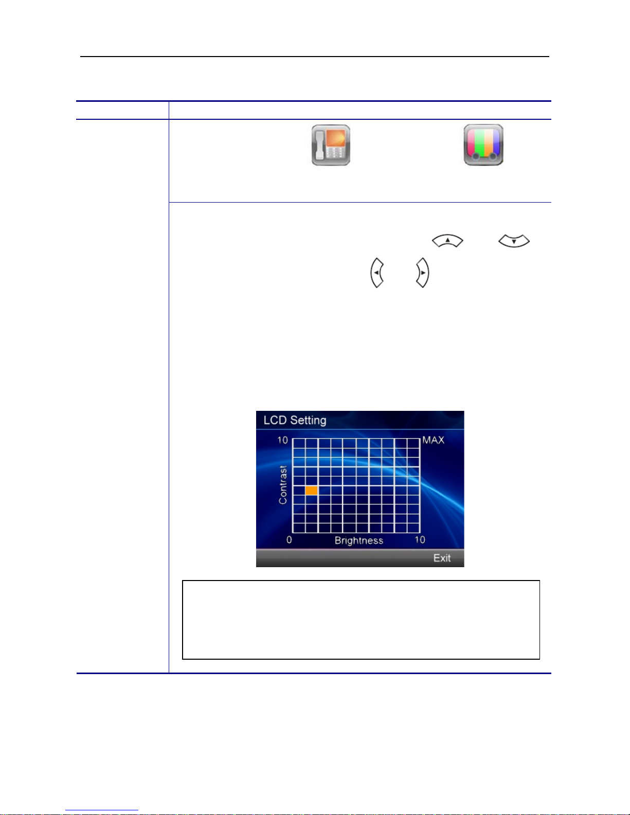
Changing the Display Contrast and Brightness
Operation Description
Menu Phone Settings Display S ettin gs LCD
Setting
Adjusting the
contrast and
brightness on
the display
To adjust your phone display to a comfortable contrast and brightness
level you prefer, please use navigation keys and to
adjust Contrast; use navigation keys and to adjust Brightness.
Besides, you can also touch a square of the panel to change contrast
and brightness concurrently.
When you feel the display is at a comfortable level, p lease press the Exit
soft key to confirm your setting and exit the LCD setting screen.
Changing the Display Wallpaper
You can change the wallpaper that appears on the standby screen.
Note: If you do not press any keys on the phone after 5 minutes of
the backlight turning on, the screen saving mode will be enabled. If
you do not press any keys on the phone after 30 minutes of the
screen saving mode enabling, the backlight will be turned off.
Page 18
WEB IP PHONE - USER MANUAL
18
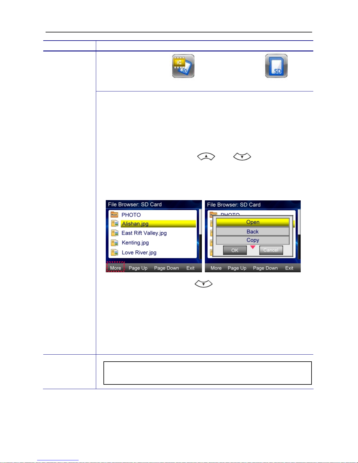
Operation Description
Menu File Browser SD Memory Card
Changing the
display
wallpaper
To change the default wallpaper to others:
1. Save JPG format photos in one SD memory card.
2. Insert the SD card to the SD card slot of the Web IP Phone.
3. Follow the steps above, and you will see all files in the SD card.
4. Use the navigation keys and to move the cursor
bar to select one photo that you would like to be the wallpaper.
5. Press the More soft key to pop up more options.
6. Use the navigation key
to move the cursor bar to Save
as wallpaper option.
7. Press the OK key to confirm the selection.
8. When returning to the standby screen, you will see the selected
photo displayed as the wallpaper.
Note: You also can select the photos in the Embedded Memory to
be the wallpaper.
Page 19
WEB IP PHONE - USER MANUAL
19
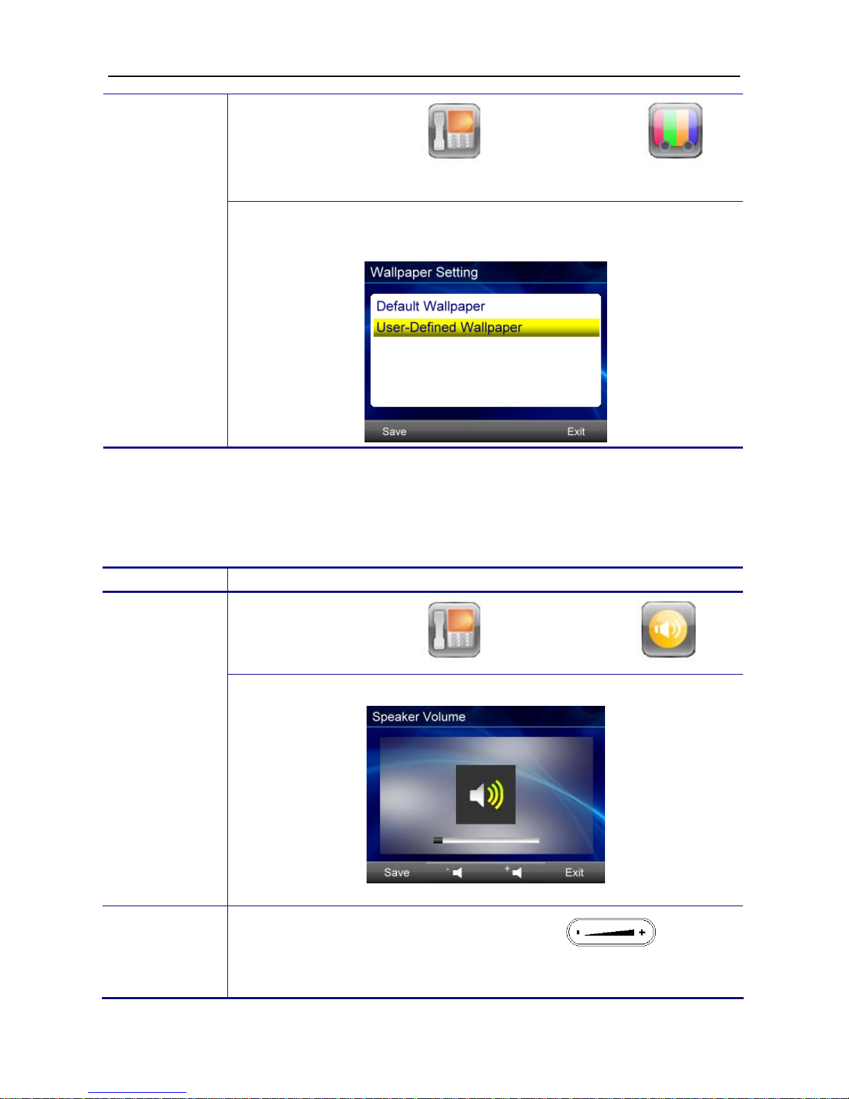
Menu Phone Settings D isplay Settings
Wallpaper Setting
Changing
back to the
default
wallpaper
You can change the wallpaper back to the default wallpaper by selecting
Default Wallpaper option.
Adjusting the Web IP Phone Volume
You can adjust speaker volume, handset volume, headset volume, speaker MIC volume,
handset MIC volume and headset MIC volume through the following procedures.
Operation Description
Menu Phone Settings Volume Settings
Adjusting the
volume
After adjusting the volume, press the Save soft key to save the setting.
For ring volume adjustment, you can press the key to
make change only when the phone is not in the Device Volume setting
menu.
Page 20

WEB IP PHONE - USER MANUAL
20
Managing Contacts
You can store a large number of contacts in the Web IP Phone’s local contact directory. In
the local contact directory, there are two directories, private and public. You can dial or
search for a con tact in bot h d irector ies , but yo u on ly c an a dd, ed it, de lete and s end contacts
in the private contact directory. In addition, you can either add contacts manually or from a
call list to the private contact directory.
Operation Description
Menu Contacts or press the hot key directly.
Adding
contacts
manually
1. Press the Add soft key to add a contact.
2. Press the Edit soft key or touch the Name field to enter edit page.
Page 21

WEB IP PHONE - USER MANUAL
21
3. Press the ABC soft key to select between numeric and upper/lower
case alphanumeric mode.
4. After entering data, press the Save or Exit soft key to save or cancel
changes.
Adding
contact s fr om
CallLog
1. Press the CallLog soft key, and then select All, Incoming, Dialed
and Missed as desired.
2. Use the navigation key and to move the selected
bar, and then press the OK key or the Details soft key to view the
details. Besides, you can touch the field to enter details page
directly.
3. Press the Save soft key to add the contact in the private contact
directory.
Menu Contacts or press the hot key directly.
Editing
contacts
1. Press the navigation key to pop up the selected bar. Use
and to move the selected bar, and then press the OK key or
the Details soft key to view the details. Besides, you can touch the
field to enter details page directly.
Page 22

WEB IP PHONE - USER MANUAL
22
2. Press the Edit soft key to enter editing contact page.
3. Use and to move the selected bar, and then press the
OK key or the Edit soft key to enter editing field page. Besides, you
can touch the field to enter editing field page directly.
4. After editing, press the Save or Exit soft key to accept or cancel the
changes.
Menu Contacts or press the hot key directly.
Deleting
contacts
1. Press the navigation key
to pop up the selected bar. Use the
navigation key and to move the selected bar, and
then press the OK key or the Details soft key to view the details.
2. Press the Delete soft key to delete the contact.
Searching for
contacts
Menu Contacts or press the hot key directly.
Page 23

WEB IP PHONE - USER MANUAL
23
Press any key of the numeric keypad after entering the Contacts menu.
The display will show the searching result according to the numeric key
you pressed. For example, when in upper case alphanumeric mode you
press the key one time, the display will show the searchi ng resu lt
as below.
When in upper case alphanumeric mode you press the key
twice, the display will show the searching result as below.
When in numeric mode
you press the key one time, the display
will show the searching result as below.
Page 24

WEB IP PHONE - USER MANUAL
24
5. Using the Basic Features of the Web IP
Phone
This chapter provides operating instructions for basic features of the Web IP Phone.
Basic Call Operations
Operation Description
1. Lift the handset.
You will hear a dial tone.
2. Use the keypad to enter the
phone number.
The LCD window
displays the digits that you
entered and the matching
numbers in Contacts.
Note: You may use the
BKSP soft key to delete the
last digit.
3. Press OK key to dial out.
Making calls
4. On-hook the handset when
your conversation is over.
Making calls
(direct IP
address
calling)
1. Lift the handset.
You will hear a dial tone.
Page 25

WEB IP PHONE - USER MANUAL
25
2. Use the keypad to enter the IP
address of the target phone.
Use the * key for entering a
dot “”.
e.g.: If you want to dial to
192.168.1.11, please
enter the following:
192*168*1*11.
Note: You may use the
BKSP soft key to delete
the last digit
3. Press OK key to dial out.
4. On-hook the handset when
your conversation is over.
1. Pick-up the handset upon
hearing the phone ringing.
Answering
calls
5. On-hook the handset when
your conversation is over.
1. Pick-up the handset.
Redialing
numbers
2. Press the REDIAL key. The
last phone number you dialed
from the phone will be
automatically redialed.
1. While being engaged in a
conversation, you may mute
the microphone by pressing
the MUTE key.
Muting the
microphone
2. The LED of the button will
become red. At this moment,
the user may speak freely; the
other party will not hear
anything.
Page 26

WEB IP PHONE - USER MANUAL
26
1. During a conversation, if the
voice volume is too low or too
high, you may adjust it.
Adjusting
the voice
volume
during a
conversation
2. Press the volume control key to
adjust the volume.
Advanced Call Operations
Operation Description
During a conversion, press the Hold key to hold the
call.
Placing calls on
hold
To resume a held call, simply press the Resume
soft key.
1. During a 2-way call, press the Transfer key to
pop up “Dialing” screen, and then enter the phone
number of the 3rd party.
Transferring
calls (Blind
transfer)
2. Press the OK key to dial out.
The call will be
transferred automatically to the other party.
Page 27

WEB IP PHONE - USER MANUAL
27
1. During a 2-way call, press the Hold key to hold
the call.
2. Press other inactive line key to pop up
“Dialing” screen, and then enter the phone number
of the 3rd party.
3. Press the OK key to dial out.
Transferring
calls (Attended
transfer)
4. The 3rd party answers the call. You may talk
with the 3
rd
party prior to transfer the call. When you
are ready to transfer the call, press the Transfer
key to transfer the held call to the 3rd party.
1. During 2 way call, press the HOLD key to hold
the call.
2. Press other inactive line key to pop up
“Dialing” screen, and then enter the phone
number of the 3rd party.
3. Press the OK key to dial out.
4. The 3rd party answers the call. Press the
CONFERENCE key to build a 3-way conference
call.
Making 3-way
conference calls
Page 28

WEB IP PHONE - USER MANUAL
28
Access Voice Mail
Voice mail is an option feature configured on the call server and may not be supported on
your particular system. For more information, contact your system administrator.
You can access voice mail messages from your phone if your system supports voice mail
function.
Operation Description
Listening to
voice messages
1. Press the hot key.
2. Follow voice prompts to retrieve your messages.
Speed-Dial Function
The Speed D ial funct ion let you store a list of 12 phone numbers that you can access easily
using a Speed Dial number from 0 to 9, * and #.
Operation Description
Assigning speed
dial key
1. Press the Speed Dial soft key.
2. Use the navigation key and to move the selected
bar, and then press the OK key or the Edit soft key to assign a
phone number to the speed dial index.
3. You can either enter a phone number manually or insert a phone
number from the Contacts. Press the Save or Exit soft key to
accept or cancel changes.
Page 29

WEB IP PHONE - USER MANUAL
29
1. Lift the handset.
You will hear a dial
tone.
Dialing a speed
dial index
2. Use the keypad to press
one of the numeric keys
for 3 seconds. The Web
IP Phone will show and
dial out the respective
phone number
automatically.
Call-Block Function
The Web IP Phone provides the possibility to block calls with a specific Caller ID. You can
input a list of 30 Caller IDs.
Operation Description
Menu Phone Settings Call Blocking
Assigning call
blocking
numbers
Use the navigation key
and to move the selected bar,
and then press the OK key or the Edit soft key to assign a phone
number to the call blocking index.
Page 30

WEB IP PHONE - USER MANUAL
30
Basic Call Features
Operation Description
If you do not want any incoming call to disturb you, please enable this
function. The caller will hear busy tone when they make calls to you.
Menu Phone Settings Call Settings Don’t
Disturb
Don’t disturb
Use the navigation key and to move the selected bar,
and then press the OK key or the Select soft key to enter Disab le/Enab le
page. Finally, press the Save soft key to confirm the change.
You can use this function to auto answer all incoming calls when you are
busy on something and hope the call can be received automatically.
Menu Phone Settings Call Settings Auto
Answer
Auto answer
Use the navigation key and to move the selected bar,
and then press the OK key or the Select soft key to enter Disab le/Enab le
page. Finally, press the Save soft key to confirm the change.
You can use this function to hear an alarm tone when you are in a call
and there is a new call coming.
Menu Phone Settings Call Settings Call
Waiting
Call waiting
Use the navigation key and to move the selected bar,
and then press the OK key or the Select soft key to enter Disab le/Enab le
menu. Finally, press the Save soft key to confirm the change.
Page 31

WEB IP PHONE - USER MANUAL
31
You can use this function to let your phone redial the number
automatically when the called party becomes available again.
Menu Phone Setting s Call Settings Call
Completion
Call
completion
Use the navigation key and to move the selected bar,
and then press the OK key or the Select soft key to enter Disab le/Enab le
menu. Finally, press the Save soft key to confirm the change.
If you are not available to answer calls, and want all incoming calls to be
forwarded to voice mail or other phone number, please enable this
function. And there are three options you can select according to your
conditions. They are Unconditional, No Answer and Busy.
Menu Phone Settings Call Settings Call
Forwarding
Call
forwarding
Use the navigation key and to move the selected bar,
and then press the OK key or the Select soft key to enter sub-menu.
Finally, press the Save soft key to confirm the change.
Note: If you choose the No Answer option, you will be prompted
to enter the timeout value (in seconds) which is for the time
between a call coming and redirecting.
Page 32

WEB IP PHONE - USER MANUAL
32
Phone Lock
Operation Description
This feature let you lock the Web IP Pho ne. While the phone is lock ed, n o
one may use it to make calls.
Menu Phone Settings Phone Lock Settings
Locking Phone
Locking
phone
Information about the Web IP Phone
You may view all related information about the Web IP Phone through the LCD menu. This
may give you, for example, the current network settings of the Web IP Phone, and the
registration status to your ITSP (Internet Telephony Service Provider).
Operation Description
Menu Information
View
information
about the Web
IP Phone
Use the navigation keys to Page Up and Page Down the
information pages you would like to view.
Note:
When you select Locking
Phone, the phone will be
locked. The default password
to unlock the Web IP Phone
is 1234.
Page 33

WEB IP PHONE - USER MANUAL
33
The following information can be viewed from the LCD screen of your Web IP Phone.
IP Address
Network Type
Subnet Mask
IPv6 Address
Gateway
Primary DNS
Network Information
Second DNS
Product Name
F/W Version
Product Information
MAC Address
Reg. Number
Reg. Status
Line 1~6 Registration Information
Reg. Server
On-phone Help for Basic Phone Operations
Operation Description
Menu Information Help
Look up help
page about
basic phone
operation
In Help page, you can find basic phone operation guide. It includes,
Display Icons
Access Phone Book
Access Voice Mail
Making Calls
Answering Calls
Placing Calls on Hold
Transferring Calls
Making 3 Way Conference Calls
Redialing Numbers
Page 34

WEB IP PHONE - USER MANUAL
34
6. Using the Advanced Features of the Web IP
Phone
This chapter provides operating instructions for the advanced features of the Web IP
Phone.
Messaging Functions
Operation
Description
Menu Messaging Instant Messaging
Using instant
messaging
You can use Instant Messaging to send and receive text messages
between Web IP Phones.
Menu Messaging E-mail
Using e-mail
You can use E-mail to send and receive emails between any devices that
have email account.
Note: To use instant message, your call server must support this
feature.
Note: To use E-mail, the Web IP Phone must register to a mail server.
Please enter all required mail registration information provided by your
service provider. After entering all required registration information, and
then press Test to verify the account is workable or not.
Page 35

WEB IP PHONE - USER MANUAL
35
Menu Messaging Answering Machine
Using
answering
machine
The answering machine is just like your local voice mail. You can record a
greeting on your phone in addition to retrieving voice messages stored on
your phone.
Multimedia Functions
Operation Description
Menu Multimedia Video Viewer
Viewing
video
1. Choose video source from either Embedded Memory or SD Memory
Card.
2. Press the Play, Pause, Forward and Backward soft keys to take
action.
3. You can adjust volume by pressing the hot key.
Note:
(1) To play video, your Web IP Phone must have MP4 decoder.
Please contact with your service provider for more information.
(2) Please note that the supported maximum size of video is 352 x
288 pixels.
Note: To use answering m achine funct ion, you must set call forward ing
to your local voice mail.
Page 36

WEB IP PHONE - USER MANUAL
36
Menu Multimedia Music Player
Playing
music
1. Choose audio source from either Embedded Memory or SD Memory
Card.
2. Press the Play, Stop and Pause soft keys to take action. Besides, you
can select to play a song once, or repeat a song, or repeat all songs by
switching playing mode: Once, Repeat and Repeat All.
3. You can adjust volume by pressing the hot key.
Menu Multimedia Photo Viewer
Viewing
photo
1. Choose photo source from either Embedded Memory or SD Memor
y
Card.
2. Press the Open, Zoom in, Zoom out and Play soft keys to take action.
3. When pressing the Play soft key, the photos will be played with music if
there is music either in Embedded Memory or SD Memory Card.
4. You can adjust volume by pressing the
hot key.
Note:
(1) Basic supported audio format is MIDI.
(2) To play MP3 format, your Web IP Phone must have MP3
decoder. Please contact with your service provider for more
information.
Note:
(1) Basic supported photo format is JPEG baseline.
(2) Please put all photos w hich a re go ing to be viewed in a file named as
PHOTO.
Page 37

WEB IP PHONE - USER MANUAL
37
Menu Multimedia Voice Recorder
Recording
audio
You can use Voice Recorder to re c o rd local voice .
To record audio, press to start recording, press to
stop recording or press to pause.
To play record files, press the Files soft key to see record files, and then
select a file to play. Besides, you can press the More soft key to select Cop
y
the file to SD memory card or Send* the file to other Web IP Phone.
File Browser
Operation
Description
Menu File Browser or
Managing
files
1. You can use File Browser to manage files in Embedded Mem ory and
SD Memory Card.
2. Press the Open, Copy, Delete, Format, Send File and Save as
Wallpaper (only available for photos) soft keys to take action.
Copy: It is for you to copy a file from Embedded Memory to SD Memory
Card, and from SD Memory Card to Embedded Memory.
Delete: It is for you to delete a file.
Format: It is for you to format Embedded Memory or SD Memory Ca rd.
Send File*: It is for you to send a file which its file size is under 2MB
between Web IP Phones. To use this function, your service provider must
provide a file sending server for your Web IP Phone.
Save as Wallpaper: It is for you to customize the wallpaper of your Web
IP Phone. You can save one photo you like to be the wallpaper.
Note: To use File Sending function, your service provider must
provide a file sending server for your Web IP Phone.
Page 38

WEB IP PHONE - USER MANUAL
38
Applications
Operation
Description
Menu Applications Alarm Clock
Using alarm
clock
You can set 5 sets of alarms for reminding function. Besides, you can set
each of alarm for alarm one time or everyday.
Menu A pplications Calendar
Using
calendar
In Calendar, you can add/delete a note or browse date.
Menu A pplications Notes
Using notes
In Notes, you can add/delete a note.
Menu A pplications World Clock
Using world
clock
In World Clock, you can browse the local time of main cities in the world.
Menu Applications Painting Board
Using
painting
board
In Painting Board, you can make a drawing or input text to share with
other users who use Web IP Phone by sending* out the file to them. To
use file sending function, your service provider must provide a file sending
server for your Web IP Phone.
Page 39

WEB IP PHONE - USER MANUAL
39
Menu Applications Surveillance
Viewing video
streaming
from IP
Camera
In Surveillance, you can view and capture video streaming sent from the
specific IP camera.
To use Surveillance application, please contact with your service provider
to obtain IP Camera information.
Menu Applications Door Phone
Enabling
door phone
function
How this function works:
When a visitor makes a call from the door phone to the office phone, the
office phone will display video streaming from the IP camera as soon as it
receives an incoming call from the door phone. You can decide to pick up
the call or reject the call after you see who is calling.
To use this function, please make all required configuration ready, and
enable door phone function.
All required configuration includes:
Phone Number: Enter the phone number of the door phone.
Cam IP Address: Enter the IP address of the IP camera.
Cam Web Port: Enter the web port of the IP camera.
Login Name: Enter the login name of the IP camera.
Login Password: Enter the password of the IP camera.
Note: The Web IP Phone only works with the specific IP Camera.
Page 40

WEB IP PHONE - USER MANUAL
40
Menu Applications Video Phone
Enabling
video phone
function
How this function works:
You make a call to your colleague. Your Web IP Phone will display the
video streaming from the IP camera aside your colleague’s Web IP Phone
as soon as your colleague picks up your call. In the meanwhile, your
colleague’s Web IP Phone will display the video streaming from the IP
camera aside your Web IP Phone.
To use this function, please make all required configuration ready on both
your phone and your colleague’s phone, and enable video phone function
on both phones.
All required configuration on your phone
includes:
Phone Number: Enter your colleague’s phone number.
Cam IP Address: Enter the IP address of the IP camera aside your colleague.
Cam Web Port: Enter the web port of the IP camera aside your colleague.
Login Name: Enter the login name of the IP camera aside your colleague.
Login Password: Enter the password of the IP camera aside your colleague.
All required configuration on your colleague’s phone includes:
Phone Number: Enter your phone number.
Cam IP Address: Enter the IP address of the IP camera aside you.
Cam Web Port: Enter the web port of the IP camera aside you.
Login Name: Enter the login name of the IP camera aside you.
Login Password: Enter the password of the IP camera aside you.
Page 41

WEB IP PHONE - USER MANUAL
41
On-Condition Function
Menu Phone Settings On-Condition Settings
Using
on-condition
function
On-condition function is for advanced call features. You can make
different settings for different call conditions. For example, when you do
not want to be disturbed by someone, you can make a setting as below.
1. Select Do not disturb in the Create Conditions from Templates.
2. Select Condition List, you will see Do not dis turb.
3. Press the Edit soft key to make further settings for Do not distur b.
4. Press the Select soft key, and then press the Next soft key.
5. The Trigger List screen shows up.
6. Select When a call incoming.
7. The Condition List screen shows up.
8. Select Condition1.
9. The Parameter Selection screen shows up.
10. Press the Select soft key.
11. The Value Input screen shows up.
12. Enter the phone number of someone you do not want to be disturbed ,
and then press the Select soft key to confirm.
13. Press the Next soft key.
14. The Action List screen shows up.
15. You can select Reject a call.
16. The Parameter for Action screen shows up.
17. For Reject a call option, you do not need to input any parameter, so
just press the Exit soft key to return to the On-condition Setting
screen.
Page 42

WEB IP PHONE - USER MANUAL
42
Programmable Keys
Menu Phone Settings EDM Set tings
Using programmable
keys
The Web IP Phone has 4 programmable keys. For each programmable
key, there are 22 options below to select. You can program each key
through this menu.
No. Function Description
1 None
Set the function key as None. When pressing the
function key, it will have no any action.
2 Line
Set the function key as Line. When p ressing the
function key, it will pop up Dialing screen using the
line as your setting.
3 Key Event
Set the function key as Key Event. When pressing
the function key, it will perform the function as your
setting. You can set one of the following key events
in the "Key" field of Button Settings page.
F_HOLD
F_CONFERENCE
F_TRANSFER
F_REDIAL
F_HANDSFREE
F_MUTE
F_CONTACTS
F_MESSAGE
F_HEADSET
4 Speed Dial
Set the function key as Speed Dial. When pressing
the function key, it will dial out the phone number as
your setting.
5 Feature Key
Set the function key to Featur e K ey. When pressing
the function key, it will dial out the number as your
setting.
Page 43

WEB IP PHONE - USER MANUAL
43
6 Call Blocking
Set the function key to Call Blocking. When
pressing the function key, the call blocking setting is
enabled, and the LED of the function key becomes
green. When the blocking number calls you, your
Web IP Phone will reject the call automatically, and
show a missed call icon on the standby screen.
7 Auto Answer
Set the function key to Auto Answer. When
pressing the function key, the Auto Answer setting
is enabled and the LED of the function key becomes
green as well as the Auto Answer icon displays on
the top line bar. No matter any number calls you,
your Web IP Phone will pick up calls automatically.
8 DND
Set the function key to DND (Don’t Disturb). When
pressing the function key, the DND setting is
enabled and the LED of the function key becomes
green as well as the DND icon displays on the top
line bar. No matter any number calls you, your Web
IP Phone will not have any incoming call displayed,
and only show a missed call icon on the standby
screen.
9
Anonymous
Call Blocking
Set the function key to Anonymous Call Blocking.
When pressing the function key, the Anonymous
Call Blocking setting is enabled and the LED of the
function key becomes green. When any anonymous
call calls you, your Web IP Phone will reject the call
automatically, and show a missed call icon on the
standby screen.
10 Phone Lock
Set the function key to Phone Lock. When pressing
the function key, the Phone Lock setting is enabled
and the LED of the function key becomes green.
You will need to enter a password to unlock your
Web IP Phone.
The default password to unlock phone is 1234.
Page 44

WEB IP PHONE - USER MANUAL
44
11 Transfer
Set the function key as Transfer. When you have
an incoming call, if you press the function key, the
incoming call will be ransferred to the phone
number as your setting.
12
Call Forward
Always
Set the function key to Call Forward Always.
When pressing the function key, the Call Forward
Always setting is enabled, and the LED of the
function key becomes green. Your Web IP Phone
will forward any incoming calls to the number as
your setting.
13
Call Forward
Busy
Set the function key to Call Forward Busy. When
pressing the function key, the Call Forward Busy
setting is enabled, and the LED of the function key
becomes green. Your Web IP Phone will forward
any incoming calls to the number as your setting
when your Web IP Phone is off hook or during a
call.
14
Call Forward
No-Answer
Set the function key to Call Forward No-Answer.
When pressing the function key, the Call Forward
No-Answer setting is enabled, and the LED of the
function key becomes green. Your Web IP Phone
will forward any incoming calls to the number as
your setting when the call does no t be p icked up in
time.
15 Voice Record
Set the function key to Voice Record. When the
"Record" key is pressed once during a call, the
phone sends a SIP INFO message with * Record:
on. Another key press stops the recording, makes
the phone send a SIP INFO message with *
Record: off.
Please be aware that the phone is only triggering
the start and end of the recording on a remote
location which has to perform the recording itself.
The phone does not record the voice streams at
all.
Page 45

WEB IP PHONE - USER MANUAL
45
16 Busy Line Field
Set the function key to Busy Line Field. When the
set number is busy, the LED of the function key is
on. If the LED of the function key is off, you can
press the function key to dial out the set number
directly. When the set number is ringing, th e LED
of the function key is blinking, and if you press this
key,you can pick up the ringing call.(for Asterisk
PBX only)
17 Orbit
Set the function key as Orbit. When pressing the
function key during a call, it will park the call in the
parking lot as your setting. This feature is useful
for call center environments and all places where
there is a great inflow of calls and some kind of
queuing is required to manage them.
18 Pick Up
It's used for SLA/BLA mode, using this feature can
pick up a ringing call on other phone. Note the SIP
server should support SLA . This function has been
tested with FreeSwitch.
19 Call Pick Up
Set the function key as Pick Up. When pressing
the function key, it will pick up the call in the
parking lot as your setting.
Note: To use this function, your server, such as
Asterisk, must support this function.
20 Call Park
Call Park Is similar to Orbit, using this feature will
transfer a call to a park queue on server, a park
queue number should be configured.
Note: To use this function, your server must
support this function.
21 DTMF
Set the function key to DTMF. When pressing the
function key during a call, the digits set in DTMF
setting will be sent out. To use this function,
please set DTMF type as RFC2833. It’s
configurable only in Administration mode.
Page 46

WEB IP PHONE - USER MANUAL
46
22 Intercom
Set the function key as Intercom. When pressing
the function key, it will dial out the phone number
directly as your setting. This feature is useful in an
office environment as a quick access key to
connect to the operator or the secretary.
For example, you want the Programmable Key 1 to be a Speed Dial key
(dial to 2100) of Line 1, you can make a setting as below.
1. Move the selected bar on FUNC1, and then press the Edit soft key.
2. The Button Settings screen shows up.
3. Move the selected bar on Function, and then press the Select soft
key.
4. Move the selected bar on 4. S pee d Dia l, an d t hen press the Select soft
key.
5. The screen returns to the Button Settings screen.
6. Move the selected bar on Line, and then press the Select soft key.
7. The Line Selection screen will show up.
8. Move the selected bar on 2. Line 1, and then press the Select soft key.
9. The screen returns to the Button Settings screen.
10. Move the selected bar on Key, and then press the Select soft key.
11. Enter “2100”, and then press the Save soft key to save the change.
12. The screen returns to the Button Settings screen.
13. Press the Exit soft key to return to the EDM Settings screen.
Note: To expand programmable keys,
you may purchase an expanded dial
module from your service provider.
Page 47

WEB IP PHONE - USER MANUAL
47
XML Web Services
Press the Services soft key on the standby screen directly.
Using XML
web
services
The XML Web Services will be offered thru the XML Server that may
support different applications for users. For example, you can view on-line
directory, weather, news, currency and stocks information in XML Web
Services. Moreover, you can order meal and control remote devices in
this menu. However, a ll cont ents in the X M L W eb S er v ice s d epend on th e
offerings of your company XML Web server or your service provider that
they can support. For XML Web Services application requirements,
please contact with your Administrator or Service provider for details.
Page 48

WEB IP PHONE - USER MANUAL
48
7. Web Configuration
Login page
When DHCP server is unavailable as well as no user assigned network parameters, the
Web IP Phone will use the factory default value listed below:
IP: 192.168.1.10
Subnet mask: 255.255.255.0
Gateway: 192.168.1.1
DNS: 168.95.1.1
Default user name of Web configuration page: user
Default user password of Web configuration page: 1111
Accessing the phone through web browser, just simply enter the “http://192.168.1.10” in
the location field of the browser. (If you are not sure about the IP address, you can examine
the current IP address through phone menu. Standby screenMenuInformation)
The following dialog box will pop up and prompt you to provide the user name and
password in order to prevent unauthorized user access the phone. Please enter the user
name and user password.
Page 49

WEB IP PHONE - USER MANUAL
49
Information
The following is the default page you will see when you login the phone’s web page.
Reboot
Reboot system.
Logout
Logout and close the browser window.
Page 50

WEB IP PHONE - USER MANUAL
50
Phone - Basic Functions
Field Name Function
Handset Mic Volume
Set the handset microphone level. Range is 1~10.
Handset Volume
Set the handset speaker level. Range is 1~10.
Speaker Mic Volume
Set the hand-free microphone level. Range is 1~10.
Speaker Vo lume
Set the hand-free speaker level. Range is 1~10.
Headset Mic Volume
Set the headset microphone level. Range is 1~10.
Headset Volume
Set the headset speaker level. Range is 1~10.
Ring
Set the ring level. Range is 1~10.
Call Forward Busy
Set a forward number for phone is in busy status.
Call Forward Unconditional
Set a forward number for phone is in any status.
Call Forward No Answer
Set a forward number for phone is in no answer status.
No Answer Timeout(s)
Set a timeout duration for phone is in no answer status.
Call forward (All)
to phone answering machine
Enable call forward to phone answering machine when
there are any incoming calls.
Call forward (No answer)
to phone answering machine
Enable call forward to phone answering machine when
phone is in no answer status.
Page 51

WEB IP PHONE - USER MANUAL
51
Enable DND
Turn on DND function.
Enable Auto A nswer
Turn on auto answer function.
Enable Echo Canceller
Turn on echo canceller.
Call Completion
Turning this setting to “on”will prompt the user to activate
call completion, if possible, while calling a number. When
the called party becomes available again, your phone will
be automatically redial the number.
Silence Suppression(VAD)
Three options: None, Off and On.
Phone Lock
Lock this phone. Default pin code to unlock it: 1234.
Enable Transfer Onhook
Turn on on-hook transfer function.
Reject Anonymou s Call
Turn on reject anonymous call function.
Enable Hold Reminder
Turn on hold reminder function.
Hold Reminder Time
Set hold reminder time.
Enable Call Waiting
Turn on call waiting function.
RTP Port
Set RTP port.
Session Time
Set session time.
Min SE Time
Set minimum session est. time.
Enum Suffix
Set root server of Enum.
Speed Dial Entry
Set the speed dial numbers for keys(for key 0-9, *, #).
Call Blocking Entry
Set the call blocking numbers.
Page 52

WEB IP PHONE - USER MANUAL
52
XML Service URL
Set the root HTTP URL of XML service. To use XML service
function, please contact with your administrator or service
provider for details.
Custom User Agent
It is used for compatible with some Cisco XML services.
Trans-File Server URL
Set the HTTP URL of trans-file server which is for file sending
application. To use this function, please contact with your
administrator or service provider for details.
Phone - Advanced Functions
Enable Auto Reply
Enable auto-reply function.
Caller Number 1, 2, 3
Set the number for matching.
Message 1, 2, 3
Enter a message that you want to leave for the caller.
Note: Auto-reply function provides a friendly reply mechanism for caller when you leave
the Phone. If you enable this function, when the set phone number calls you, the phone
will auto reply a MESSAGE as you set to t he calle r. Otherwise, the phone will ring until
timeout.
Page 53

WEB IP PHONE - USER MANUAL
53
Email User Name
Set E-mail displayed name for E-Mail application.
Email Address
Set E-mail address for E-Mail application.
Email Login Account
Set authorization user name for E-Mail application.
Email Login Password
Set authorization password for E-Mail application.
Email POP3 Server
Set POP3 server address for E-Mail application.
Email POP3 Port
Set POP3 server port for E-Mail application.
Email SMTP Server
Set SMTP server address for E-Mail application.
Email SMTP Port
Set SMTP server port for E-Mail application.
Enable Door Phone
Click to enable door phone function.
Door Phone Number
Set the phone number of the Web IP Phone that is used
as door phone.
Door Phone Camera IP/ Port
Set the IP address and port number of the IP camera
placed aside the door phone.
Door Phone Camera
User Name
Set the login user name of the IP camera placed aside
the door phone.
Door Phone Camera
Password
Set the login password of the IP camera placed aside the
door phone.
Page 54

WEB IP PHONE - USER MANUAL
54
Enable Video Phone
Click to enable video phone function.
Video Phone Number
Set the phone number of the Web IP Phone that is used
as video phone.
Video Phone Camera IP/ Port
Set the IP address and port number of the IP camera
placed aside the video phone.
Video Phone Camera
User Name
Set the login user name of the IP camera placed aside
the video phone.
Video Phone Camera
Password
Set the login password of the IP camera placed aside the
video phone.
IP Camera Location
Set a readable name or location for the IP camera.
IP Address
Set IP address of the IP camera.
Connec tion Mode
Set the mode of IP camera connection. There are two
modes, HTTP and RTSP.
Login Name
Set login user name of the IP camera.
Login Password
Set login password of the IP camera.
Web Port
Set the port number of HTTP mode.
RTSP Port
Set the port number of RTSP mode.
RTSP Path
Set the RTSP path.
Note: To use IP Camera related applications, such as surveillance, door phone and
video phone, you need to have a specific IP camera. Please contact with your service
provider for details.
Page 55

WEB IP PHONE - USER MANUAL
55
Phone - On Conditions
On Condition Template
Upload a new template file for On-Condition feature. For default
template file content, please refer to Appendix A, page xx.
Please note that the new update file will replace of the original
template file in the phone.
On Condition File
Upload new setting items for On-Condition feature. For new
setting file example, please refer to Appendix B, page xx.
Please note that the new update file will replace of the original
template file in the phone.
Name
Set the name for new On-Condition item.
Trigger
Select the trigger event for the new On-Condition item.
Condition 0~4
Set the conditions for the new item, max. to 4 conditions. If you let
all them empty, it will use “*” instead; it means always true.
Action
Set an action for the new On-Condition item. Each action may
have 0-5 parameters to be set.
Page 56

WEB IP PHONE - USER MANUAL
56
Phone - Key Settings
Function Key 1, 2, 3, 4
Set a specified function for each function key (1-4). There are
many advanced call features that you can select from the list.
Line Supported 1, 2, 3, 4
Select a line number (1-6) which the function key assigned to.
Key 1, 2, 3, 4 Number
Set a number for the function key.
Line Key 1, 2, 3, 4, 5,6
Set a specified function for each line key (1-6). There are
many advanced call features that you can select from the list.
Line Supported 1, 2, 3, 4,
5, 6
Select a line number (1-6) which the line key assigned to.
Line Key 1, 2, 3, 4, 5, 6
Number
Set a number for the line key.
Page 57

WEB IP PHONE - USER MANUAL
57
Hot Key:
MSG, Transfer,
Conference, Redial,
Contacts, Hold
Set a specified function for each hot key. There are many
advanced call features that you can select from the list.
Line Supported
Select a line number (1-6) which the hot key assigned to.
Hot Key Number
Set a number for the hot key.
Page 58

WEB IP PHONE - USER MANUAL
58
System Setting
User Name
Set the name for user mode (default: user)
User Password
Set the password for user mode(default: 1111)
Auto DST
Enable auto DST (daylight saving time).
Daylight Saving Time
Set a value for Daylight Saving Time. There are three
options, -1, 0 and 1.
Start on
Set start time for DST.
End on
Set end time for DST.
Time Format
Select a time format showed on the phone LCD display.
Time Zone
Set a time zone for the phone.
Save Settings
Save changes in this page to the phone.
Cancel
Discard all changes in this page.
Logout
Log out and close the browser window.
System Log
Press the button to pop up the system log web page.
Set to Default
Press the button to set all parameters of the phone to default.
The phone will auto reboot to make new parameters take
effect.
Clear Phonebook
Press the button to clear up the private phonebook data of the
phone.
All Default
Press the button to set all parameters of the phone to default
as well as clear all phonebook data. The phone will auto
reboot to make new parameters take effect.
Page 59

WEB IP PHONE - USER MANUAL
59
Contacts - Priv ate Phonebook
Upload Phonebook File
Upload “PhoneBook.xml” to the private phonebook.
Download Phonebook
Download the current phonebook data from the phone.
Group
Set a group for a phonebook item
CallOut
Call the phonebook number via web page. It is similar to
click-to-dial feature.
Delete
Delete the phonebook number via web page.
Contac ts - Public Phonebook
Upload Phonebook File
Upload phonebook data from the computer to the public
phonebook of the phone. Please note that public phonebook
data is read only, user can’t edit the data.
Page 60

WEB IP PHONE - USER MANUAL
60
EDM Setting
EDM Button 1, 2,…,11
Set a function for the EDM key.
Line 1, 2, … , 6
Select a line for the EDM key.
Button 1, 2, … , 11 Number
Set a number for the EDM key.
Note: The EDM setting page will not appear if the EDM is not plugged into the phone.
Page 61

WEB IP PHONE - USER MANUAL
61
8. Troubleshooting
Symptom Check & Remedy
No operation
Check if the power adapter is properly connected.
Check if the Ethernet cable is properly connected.
No dial tone
Check if the handset cord is properly connected.
Check if the power adapter is properly connected.
LAN connection lost
status message
Check if the Ethernet cable is properly connected
I cannot make call
Check the status of your SIP registration status or
contact your administrator, supplier or ITSP for more
information or assistance.
My IP Phone cannot
receive any phone call
Check if the Ethernet cable is properly connected
Check the status of your SIP registration status, or
contact your administrator, supplier or ITSP for more
information or assistance.
I cannot connect to the
configuration website of
the IP Phone
Check if the Ethernet cable is properly connected
Check the IP address of the IP Phone
Check if your firewall/NAT settings is correct
Page 62

WEB IP PHONE - USER MANUAL
62
9. Appendices
Appendix A: On Condition Template Profile
<?xml version=" 1.0" encoding="utf-8" standalone="yes" ?>
<OCTTemplates>
<Template>
<Name>Do not disturb</Name>
<Trigger>InComingCall</Trigger>
<Condition>*</Condition>
<Action>RedirectCall</Action>
</Template>
<Template>
<Name>C a ll Forward U nc onditional</Name>
<Trigger>InComingCall</Trigger>
<Condition>*</Condition>
<Action>RedirectCall</Action>
</Template>
<Template>
<Name>Call Forward Busy</Name>
<Trigger>Line-Busy</Trigger>
<Condition>*</Condition>
<Action>RedirectCall</Action>
</Template>
<Template>
<Name>Call Forward No answer</Name>
<Trigger>Line-NoAnswer</Trigger>
<Condition>*</Condition>
<Action>RedirectCall</Action>
</Template>
<Template>
<Name>Call Blocking</Name>
<Trigger>InComingCall</Trigger>
<Condition>
<Param>
<Name>REMOTEEXTENTION</Name>
<Hint>The Number to Block</Hint>
</Param>
</Condition>
<Action>RejectCall </Action>
</Template>
</OCTTemplates>
Page 63

WEB IP PHONE - USER MANUAL
63
Appendix B: On Condition Table Ac tion Configuration Profile
<?xml version=" 1.0" encoding="utf-8" standalone="yes" ?>
<OCTSetings>
<Setting>
<Name>Se tting A bc</Name>
<Trigger>IncomingCall</Trigger>
<Condition>*</Condition>
<Action>http://127.0.0.1/build-in/function?param1=value1</Action>
</Setting>
<Setting>
<Name>Se tting A bc</Name>
<Trigger>IncomingCall</Trigger>
<Condition>*</Condition>
<Action>http://127.0.0.1/build-in/function?param1=value1</Action>
</Setting>
<Setting>
<Name>Se tting A bc</Name>
<Trigger>IncomingCall</Trigger>
<Condition>*</Condition>
<Action>http://127.0.0.1/build-in/function?param1=value1</Action>
</Setting>
</OCTSetings>
===== The End of Document ======
 Loading...