

Page 1

1
Copyright © 2010 TECOM Co., Ltd.
All Rights Reserved.
IG6600
-
IP2032
Administrator’s Manual
Page 2

IP2032 ADMINISTRATOR’S MANUAL
2
Environment
The phone you have purchased must not be disposed of with household waste. You should
return these to your distributor if they are to replace or dispose of them in an approved
recycling centre.
FCC Statement
This equipment generates, uses, and can radiate radio frequency energy and, if not
installed and used in accordance with the instructions in this manual, may cause
interference to radio communications. This equipment has been tested and found to comply
with the limits for a Class B computing device pursuant to Subpart J of Part 15 of FCC rules,
which are designed to provide reasonable protection against radio interference when
operated in a commercial environment. Operation of this equipment in a residential area is
likely to cause interference, in which case the user, at is own expense, will be required to
take whatever measures are necessary to correct the interface.
CE Declaration of Conformity
This equipment complies with the requirements relating to electromagnetic compatibility,
EN55022 class B for ITE and EN 50082-1. This meets the essential protection
requirements of the European Council Directive 89/336/EEC on the approximation of the
laws of the Member States relating to electromagnetic compatibility.
Copyright Notice
All rights reserved. No part of this publication may be reproduced, transmitted, transcribed,
stored in retrieval system or translated in to any language or computer language, in any
form or by any means, electronic, mechanical, magnetic, optical, chemical, manual, or
otherwise, without the prior written permission of Company.
Company reserves the right to revise the publication and make changes from time to time in
the contents hereof without obligation of this company to notify person of such revision or
changes. The material contained herein is supplied without representation or warranty of
any kind. The Company therefore assumes no responsibility and shall have no liability of
any kind arising from the supply or use of this document or the material contained herein.
Trademarks
Windows 98/2000/XT/NT™ and Internet Explorer™ are registered trademarks of Microsoft
Corporation. All other company, brand and product names, like Netscape Navigator™ are
trademarks or registered trademarks of their respective owners.
ISO-9001ISO-9001
Page 3

IP2032 ADMINISTRATOR’S MANUAL
3
WARNING!
1. Read these installation instructions carefully before connecting the IP phone to its
power adapter.
2. To reduce the risk of electric shock, do not remove the cover from the IP phone or
attempt to dismantle it. Opening or removing covers may expose you to dangerous
voltage levels. Equally, incorrect reassembly could cause electric shock on re-use of the
appliance.
3. Do not expose the IP phone to fire, direct sunlight or excessive heat.
4. Do not expose the IP phone to rain or moisture and do not allow it to come into contact
with water.
5. Do not install the IP phone in an environment likely to present a Threat of Impact.
6. You may clean the IP phone using a fine damp cloth. Never use solvents (such as
trichloroethylene or acetone), which may damage the phone’s plastic surface and LCD
screen. Never spray the phone with any cleaning product whatsoever.
7. Take care not to scratch the LCD screen.
8. The IP phone is designed to work in temperatures from 0oC to 45oC (32oF to 104oF).
9. The IP phone must be installed at least 1 meter from radio frequency equipment, such
as TVs, radios, hi-fi or video equipments (which radiate electromagnetic fields).
10. Do not connect the LAN/PC port to any network other than an Ethernet network.
11. Do not attempt to upgrade your IP phone in an unstable power environment. This could
cause unexpected damages.
12. Do not work on the system during lightning storms. Please disconnect all cables.
13. Children don't recognize the risks of electrical appliances. Therefore use or keep the
phone only under supervision of adults or out of the reach from children.
14. No repair can by performed by the end user, if you experience trouble with this
equipment, for repair or warranty information, please contact your supplier.
Electrical Powering:
The IP2032 can be powered with PoE Switch or power adaptor in the package, the power
adaptor must be 5V/2A. Any damage caused to the IP2032 as a result of using
unsupported power adaptors will not be covered by the manufacturer’s warranty.
Product Disposal Warning:
Ultimate disposal of this product, accessories, packing, especially the batteries should be
handled carefully for recycle and nature protection in accordance with national laws and
regulations.
!
Page 4

IP2032 ADMINISTRATOR’S MANUAL
4
1. Contents
1. Contents ......................................................................................................................4
2. Getting Started............................................................................................................6
3. Overview of the IP2032...............................................................................................7
The Front-View of the IP2032.......................................................................................8
The LED Indication ..................................................................................................... 11
The LCD Indication .....................................................................................................12
The Connectors of the IP2032....................................................................................13
Hardware Installation ..................................................................................................14
4. General Operations ..................................................................................................16
Introduction.................................................................................................................16
Register to IG6600 ..............................................................................................16
Calls ....................................................................................................................16
Caller ID & User ID ..............................................................................................16
To Install the IP2032 ............................................................................................16
To Configure Your IP2032 for Service..................................................................16
Basic Call Features.....................................................................................................18
Making a Call.......................................................................................................18
Making a Call via Specific Trunk..........................................................................18
Receiving a Call...................................................................................................19
Receiving a Call via Specific Trunk......................................................................19
Last Number Redial.............................................................................................19
Mute the Microphone...........................................................................................19
Adjust the Voice Volume During a Conversation .................................................19
Call Record.................................................................................................................20
Review Dialed Calls.............................................................................................20
Review Received Calls........................................................................................20
Review Missed Calls ...........................................................................................20
Information about the IP2032 .....................................................................................22
View Information about the IP2032......................................................................22
5. Advanced Operations...............................................................................................23
Network Settings.........................................................................................................23
Static IP Address .................................................................................................23
Dynamic IP Address (DHCP)...............................................................................24
PPPoE.................................................................................................................24
Advanced Call Operations ..........................................................................................26
Page 5

IP2032 ADMINISTRATOR’S MANUAL
5
Call Hold..............................................................................................................26
3-Way Conference Call........................................................................................26
Call Transfer (Blind Transfer)...............................................................................26
Call Transfer (Attended Transfer) ........................................................................27
Phonebook .................................................................................................................28
Phonebook (Browse and Dial a Number) ............................................................28
Phonebook (Add or Edit a Number).....................................................................28
Phonebook (Delete a Number) ............................................................................29
Speed Dialing .............................................................................................................30
Speed Dialing (Add, Edit, or Delete a Number) ...................................................30
Dial a Speed Dialing Number...............................................................................30
Blocking List ...............................................................................................................31
Caller Blocking (Add, Edit, or Delete a Number)..................................................31
Call and Phone Management .....................................................................................32
Call Forward ........................................................................................................32
Auto Answer ........................................................................................................32
DND.....................................................................................................................33
6. Web Configuration....................................................................................................34
Login Information........................................................................................................34
Configuration Pages ...................................................................................................36
Information Page .................................................................................................36
Network Page ......................................................................................................37
Phone Page.........................................................................................................39
SW Upgrade Page...............................................................................................42
SIP Page .............................................................................................................44
System Page .......................................................................................................50
Phonebook ..........................................................................................................52
7. Features & Specifications........................................................................................54
8. Troubleshooting........................................................................................................58
9. Glossary ....................................................................................................................59
Acronyms....................................................................................................................59
Terminology ................................................................................................................60
Page 6

IP2032 ADMINISTRATOR’S MANUAL
6
2. Getting Started
This section will help you quickly find the information that you need to make use of the full
features of IP2032.
You want to… Page Link
Have an overview of the IP2032. 7
Understand the front-view of the IP2032. 8
Understand the LED indication. 11
Understand the LCD indication. 12
Understand the connectors of the IP2032. 13
Understand the hardware installation 14
Make/receive calls. 18
Hold a call, make a three-way conference call, or
transfer a call.
26
Use the phonebook. 28
Use the Speed Dialing feature. 30
Setup the IP2032 via web. 34
Changing network settings via web. 37
Page 7

IP2032 ADMINISTRATOR’S MANUAL
7
3. Overview of the IP2032
The IP2032 is an internet telephony desktop phone that connects to intelligent gateway
IG6600 with an Ethernet cable rather than traditional a PSTN line. Basically, it needs to be
connected to LAN side or WAN side of IG6600. Like a traditional office telephone, it can
deliver good voice quality and perform a great number of PBX-equivalent call features.
The IP2032 can transfer and receive voice via IP network. Therefore, it can be deployed
and connected all over the world among headquarter and remote branch offices. Since it is
a stand-alone and “always-on” terminal, there is no need to have any active PC to let it work.
The IP2032 is completely stand-alone.
The IP2032 comes with a graphic LCD display, traditional keypad, several function keys,
handset, I/O ports, and PoE (Power-over- Ethernet) /Power adaptor. It can be installed and
placed on the desktop or mounted on the wall.
Page 8
IP2032 ADMINISTRATOR’S MANUAL
8
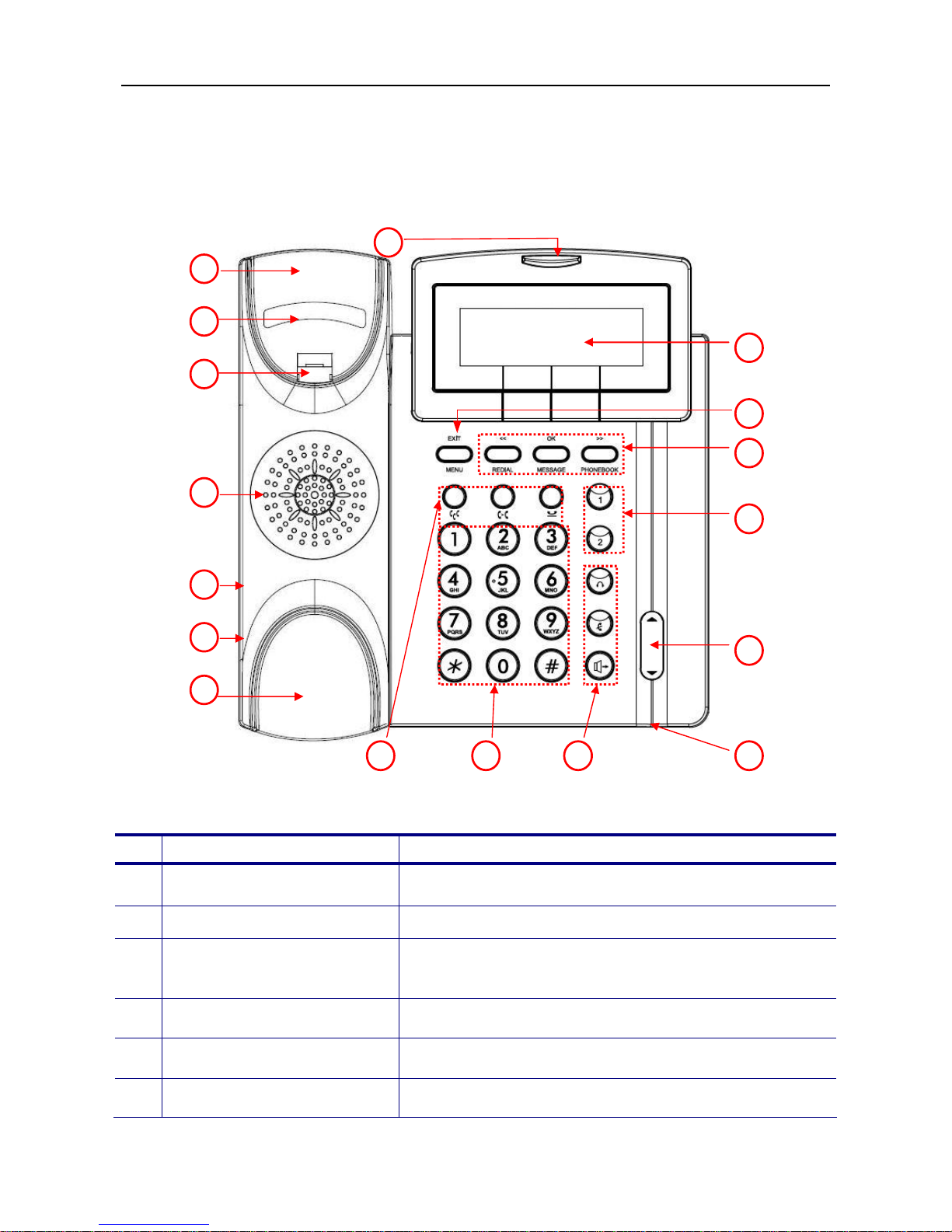
The Front-View of the IP2032
The figure below illustrates the front view of the IP2032. With the point numbers, you can
find its name and a simple description of the part in the following table.
No
Part Name Description of function
1
Handset Top Cradle For the placement of handset (Receiver end).
2
Hook Switch To hang-on and hang-off of handset.
3
Latch
To latch the handset from drop when phone is
mounted on the wall.
4
Speaker For ring and receiver of hands-free talking.
5
Handset Cord Jack RJ-9 jack for the handset.
6
Headset Cord Jack RJ-9 jack for the headset.
2 3 4 6 5 1 7 8 15 17 16 10 11 12 13 9 14
Page 9
IP2032 ADMINISTRATOR’S MANUAL
9
7
Handset Bottom Cradle For the placement of handset (Transmitter end).
8
The message LED. This red LED is used to indicate
incoming call arrival, register status, or message
waiting.
9
LCD
The LCD screen is used to display phone’s settings,
time and date, phone numbers, call status and so
forth.
10
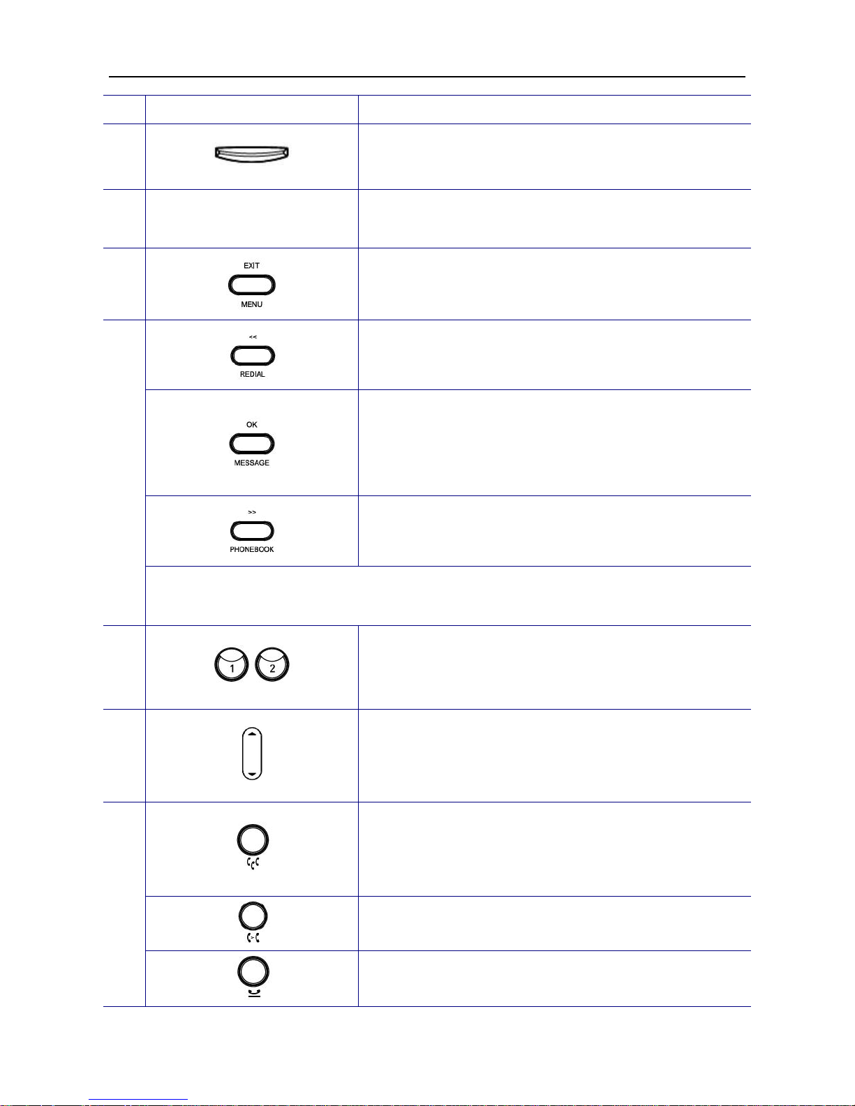
The MENU/EXIT key. In idle state, press it to go into
phone’s menu. When in phone’s menu, press it to go
back to previous menu level.
The REDIAL/<< key. In idle state, press it and choose
a dialed number to redial. In phone’s menu, press it to
go to upper menu item.
The MESSAGE/OK key. In idle state, press it to dial
mailbox number to access voice messages from
IG6600. In phone’s menu, it’s used to validate the
selection. For dialing state, it’s used to dial out the
inputted phone number immediately.
The PHONEBOOK/>> key. In idle state, press it to go
into phonebook menu. In phone’s menu, press it to go
to lower menu item.
11
The above three keys are also softkeys. The key’s function depends on its
corresponding content displayed on the LCD.
12
Two Line keys. These two keys can be used for line
selection or programmable features. A red LED is
associated with each key to indicate its line/call/feature
status.
13
The Volume Control/Navigation key. While the phone
is in idle state, the ring volume is adjusted. While in
talking state, the Handset, Speaker, or Headset
receiving volume is adjusted. It is also used to
navigate items in phone’s configuration menu.
The CONFERENCE key. When there are two
connected calls in the meantime, press it to create a
conference call. One party could hear the voice of the
other two parties. It is a voice-bridged function.
The TRANSFER key, press it then dial the other phone
number to transfer a call to another IP phone.
14
The HOLD key, press it to put the current call on hold.
Press again to resume the held call.
Page 10
IP2032 ADMINISTRATOR’S MANUAL
10
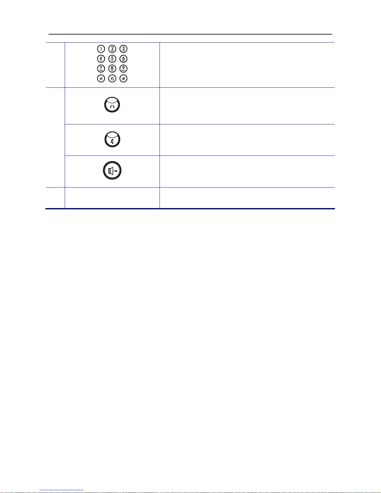
15
[1], [2], …, [9], [*], [0], [#]: The numeric keypad for
dialing numbers.
This HEADSET key. It is used to activate/de-activate
the headset. Press HEADSET key first then press
SPEAKER key to establish a call by headset. A red
LED is associated to indicate its status.
This MUTE key. It is used to activate/de-activate the
voice transmission from this IP phone. A red LED is
associated to indicate its status.
16
This SPEAKER key is used to switch the voice path
between handset and phone’s speaker. A red LED is
associated to indicate its status.
17
Microphone Hole
A small hole for hands-free microphone input under
the front edge of IP phone.
Page 11
IP2032 ADMINISTRATOR’S MANUAL
11
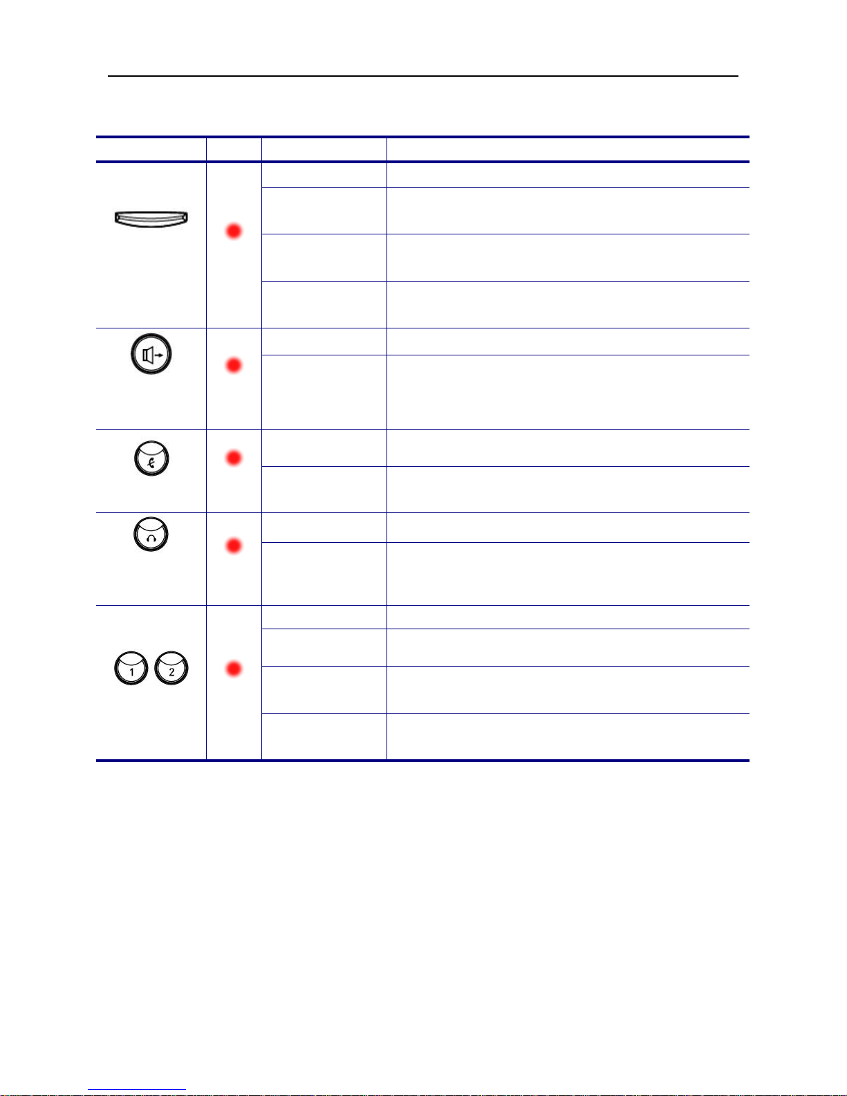
The LED Indication
LED Color
Status Description
Off Idle or no new message.
Blinking
Slowly
New voice message indication.
Blinking
Rapidly
There is an incoming call.
MESSAGE
LED
Red
Blinking
Continuously
IP2032 cannot register to IG6600.
Off The hands-free speaker is not in use.
SPEAKER
key
Red
Steady
While in on-hook dialing mode or hands-free
talking mode.
Off
The microphone is active for handset, headset or
hands-free mode.
MUTE key
Red
Steady
The microphone is inactive for handset, headset or
hands-free mode.
Off The headset mode is disabled.
HEADSET
key
Red
Steady The headset mode is enabled.
Off The trunk line is un-activated or idle.
Steady The trunk line is active (dialing, or during a call).
Blinking
Slowly
The call of relative trunk line is on hold.
Line keys
Red
Blinking
Rapidly
There is an incoming call from that trunk line.
Page 12
IP2032 ADMINISTRATOR’S MANUAL
12
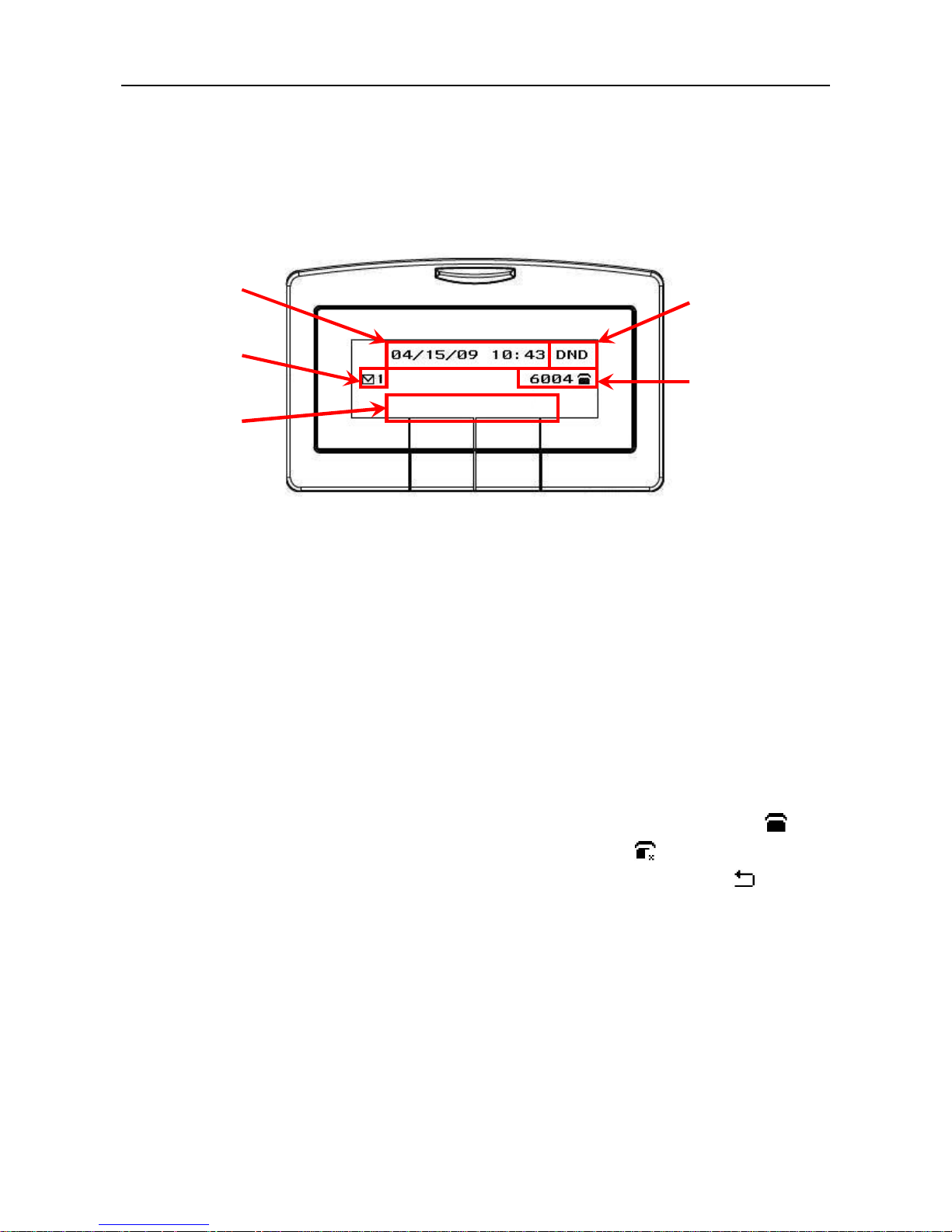
The LCD Indication
The following figure shows a standard format of LCD screen. There are 3 soft keys
associated with the operation of LCD display. For different menu or status, the display
format will be changed accordingly.
Date and Time: If Network Time Server is set, phone will sync the correct time to time
server according to user’s time zone setting. If not, it shows the passed time since latest
boot.
Message Indication: If voice messages are notified by IG6600, phone will show the
number of unread messages.
DND Indication: If DND (Do Not Disturb) function is enabled, phone will show “DND” on
LCD.
Extension Number and Status Indication: There are three line statuses, registered,
un-registered, phone’s always call forward. For registered status, phone will show icon
after line number. For un-registered status, phone will show icon after extension
number. For registered status, if enable phone’s always call forward function, icon will
replace the original registered icon.
Date and
Time
Message
Indication
Softkeys
DND Indication
Extension Number
and Status
Indication
Page 13
IP2032 ADMINISTRATOR’S MANUAL
13
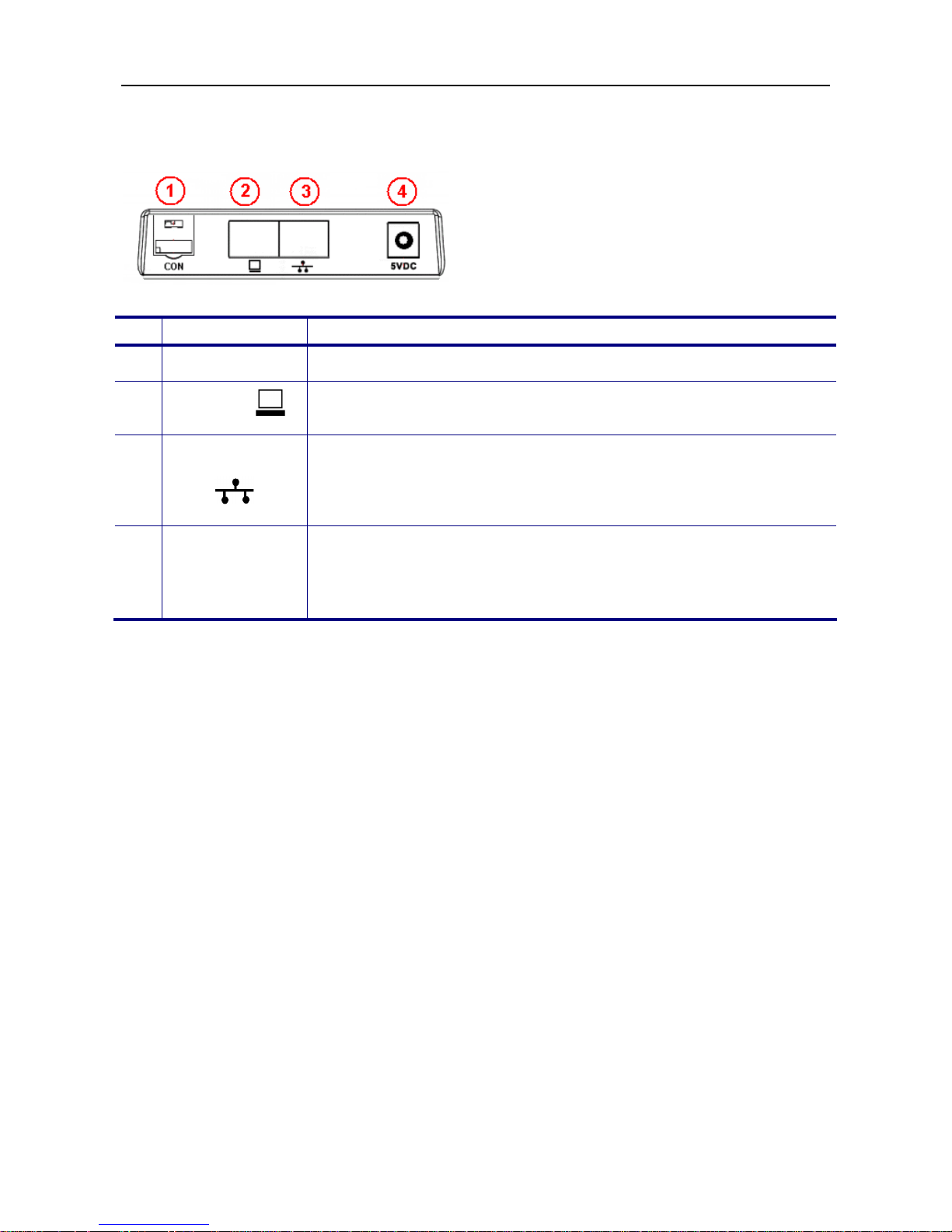
The Connectors of the IP2032
No
Part Name Description of function
1 CON
Console port reserved for engineering service only.
2
PC port
RJ-45 Jack 100/10Mbps Ethernet port for connecting to PC.
Phone could be used as a switch for PC to access the IP network.
3
LAN port
RJ-45 Jack 100/10Mbps Ethernet port for connecting to IP
network. It also support PoE, the power can come from Ethernet
cable instead using 5V power adaptor for power port.
Note: PoE means Power over Ethernet (IEEE802.3af standard).
4 Power port
To connect the power adaptor, please use standard power adaptor
supplied (5VDC/2A). This device can support power auto-switch
function if the AC power is outage and the device will switch the
power from PoE LAN port.
Page 14
IP2032 ADMINISTRATOR’S MANUAL
14
Hardware Installation
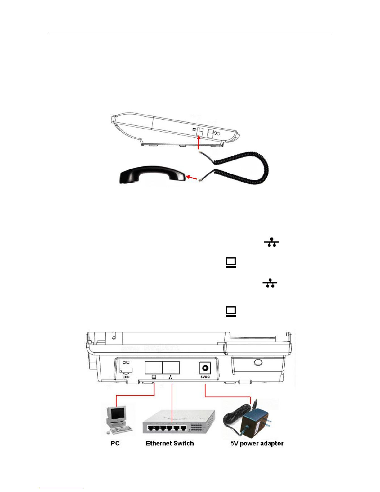
Connect the Handset:
Unpacking the box, you can get the handset and handset cord and then you can
connect the handset cord to the handset jack of the phone with the handset as the following
figure.
Connect the Cables:
Then you can find the connection ports on the rear panel of the phone. Please get two
Ethernet cables and follow the installation steps below:
(1) If your Ethernet Switch can offer you PoE (Power over Ethernet) power:
- Please connect an Ethernet cable to the Ethernet Switch from LAN port. Then
you will see the phone is powered and booting.
- Please connect your PC with an Ethernet cable to PC port.
(2) If your Ethernet Switch doesn’t support PoE function:
- Please connect an Ethernet cable to the Ethernet Switch from LAN port.
- Get the 5V/2A power adaptor attached and plug it to the outlet; then plug the barrel to
the “5V DC” Power port. Then you will see the phone is powered and booting.
- Please connect your PC with an Ethernet cable to PC port.
Page 15
IP2032 ADMINISTRATOR’S MANUAL
15
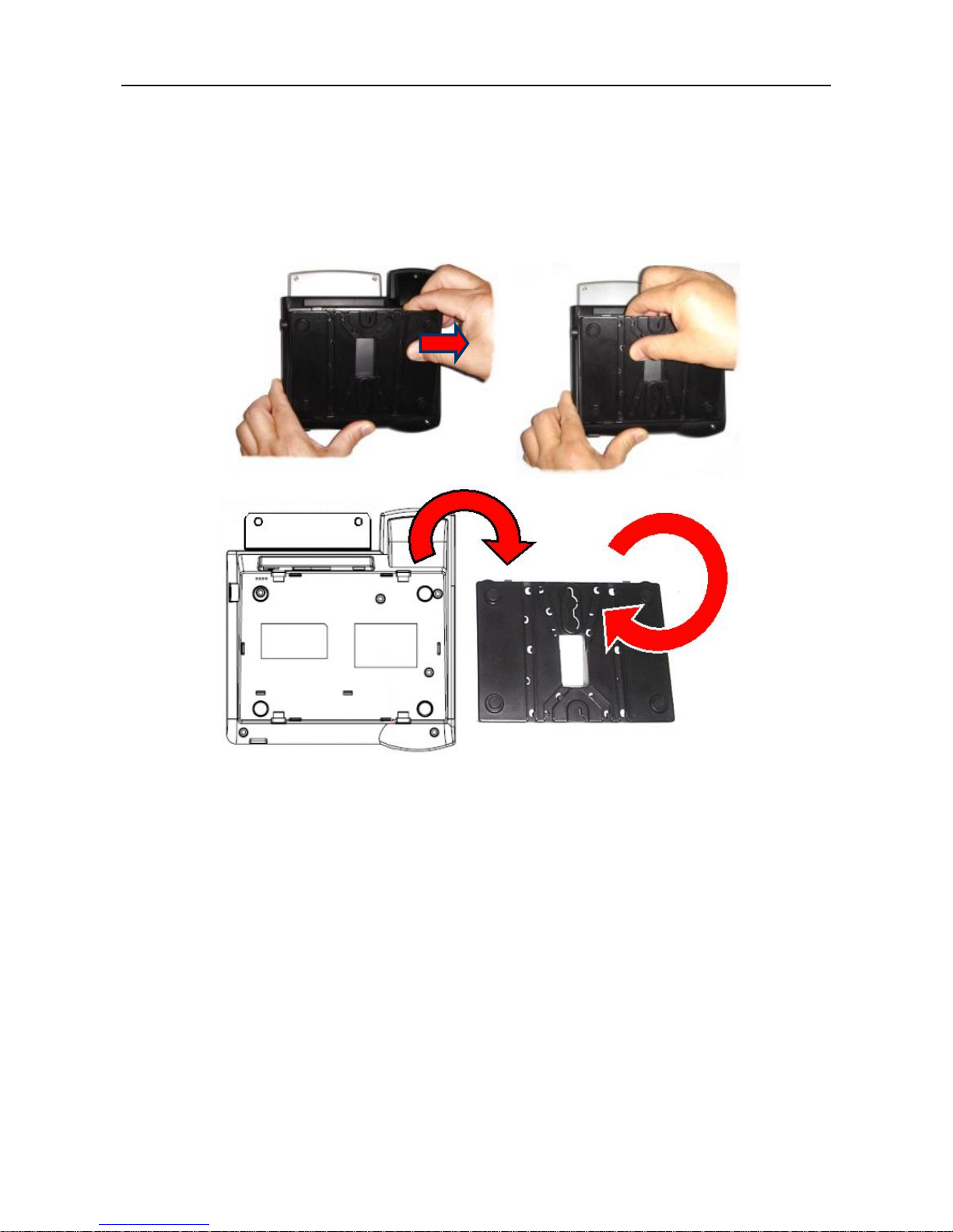
Change the stand’s direction for wall-mount use:
The phone was installed with a wedge stand together in the package. There are two
types for using the wedge stand. One is used to stand on the desk; another is used to place
on the wall. The figure below shows how to take off the wedge stand. There are two clips on
the top edge of the wedge stand. Please press these two clips to out of the top dowels, the
wedge stand can be taken off.
If you want to place the phone on the wall, please follow the steps bellow:
(1) After taking off the wedge stand, please reverse it for 180 degrees (please see the
figure above).
(2) Place the wedge stand back to the phone. Please align the clips to the bottom dowels.
(3) If needed, please drill holes and drive nails into the wall firstly. Please make sure the
hole locations are matched with the holes on the wedge stand.
(4) Mount the phone on the wall.
(5) Finally, plug cables and power adaptor to the phone.
Page 16

IP2032 ADMINISTRATOR’S MANUAL
16
4. General Operations
Introduction
To operate the IP2032 with IG6600, you need to know some conventions that will be
mentioned in this manual. In the following descriptions, we will introduce some
terminologies for your understanding.
Register to IG6600
When IP2032 firstly connecting to LAN side of IG6600 or at WAN side but in the same
subnet, IG6600 will assign an unused phone number to IP2032. After that, even if IP2032
reboot, IG6600 will assign the same phone number to it. So IP2032 can register to IG6600
automatically in the following times.
Calls
The “Call” in this manual represents a connection with outside party. IP2032 supports 2
simultaneous calls, i.e. IP2032 can use 2 channels at the same time. IP2032 can dial the
destination phone number directly for making a phone call. IP2032 supports 2 line keys.
User can press line key to choose IP or PSTN trunks which the IG6600 registered to make
an outgoing call. User can also dial IP or PSTN trunk access number for making an
outgoing call. User can hold one call and talk to the other. Therefore, the IP2032 is said to
support multiple-call appearance.
Caller ID & User ID
If the caller didn’t choose to hide his number and if the network supports the Caller ID
feature, the caller's phone number is shown on the screen when you receive a call. If the
caller choose to hide his number or the network doesn’t support the Caller ID feature, the
IP2032 will display the user’s ID of the caller if it is available.
To Install the IP2032
Before the operation of IP2032, you have to install the phone well into the network. Please
refer to previous section “The Connectors of the IP2032”. Connecting the LAN port to
IG6600 or to hub/switch with an Ethernet cable, then connect the handset to handset port
with a cord. After that, you could plug the power adaptor to power port, the phone will
switch on and work normally.
To Configure Your IP2032 for Service
Furthermore, you have to configure the phone well before operation. You may refer to this
administrator manual for full information on how to configure all the settings of the IP2032.
Now, if the IP2032 is already connected to IG6600, please follow the following chapters to
Page 17
IP2032 ADMINISTRATOR’S MANUAL
17
operate the phone.
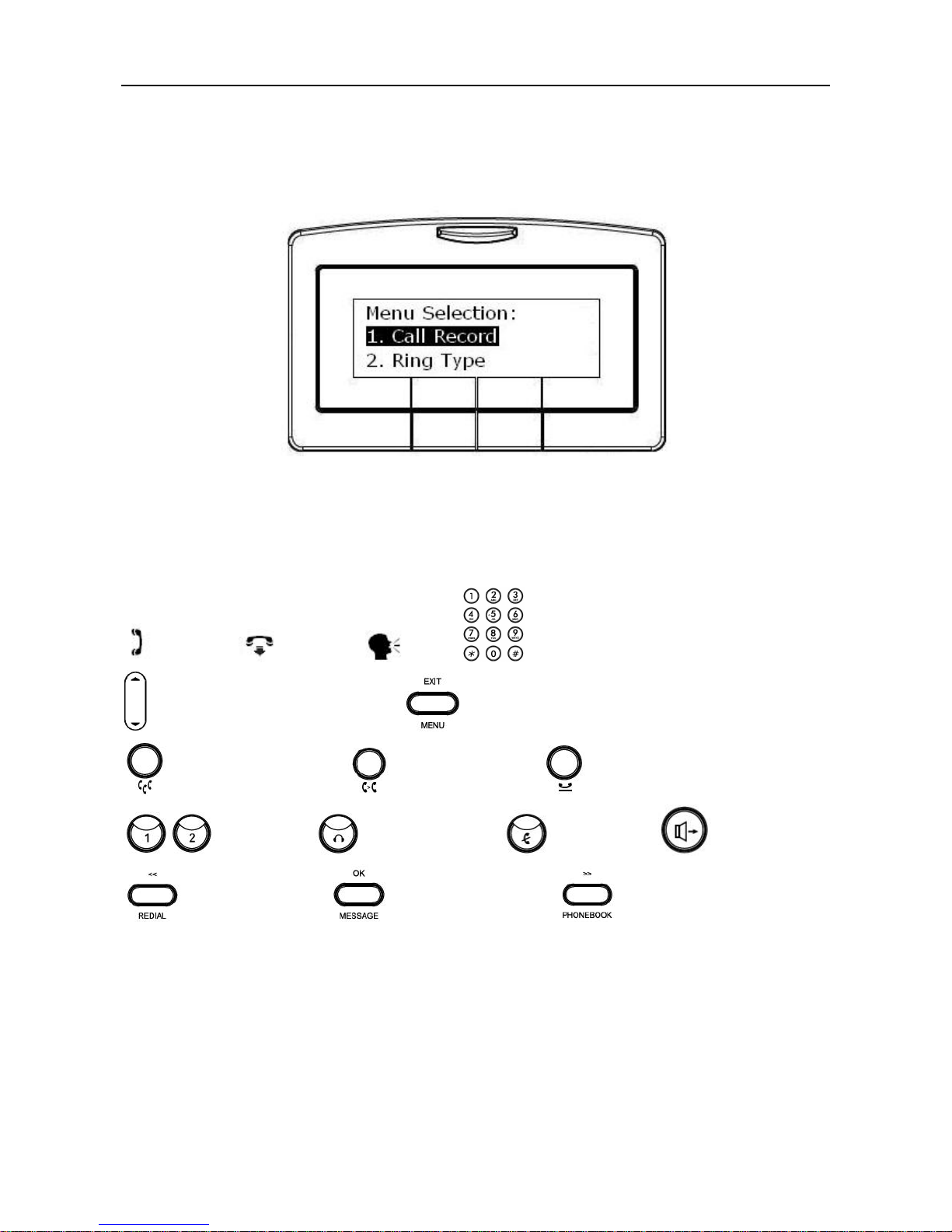
The configuration menu to configure IP2032 is as follows:
You may navigate through the menu with the navigation key. The following sections will
describe how you can setup your IP2032 through this menu.
Here lists several meanings of icons for you to easily understand the call features:
Off-hook On-hook Talk Keypad
Volume Control/Navigation key MENU/EXIT key
CONFERENCE key TRANSFER key HOLD key
Line keys HEADSET key MUTE key SPEAKER key
REDIAL/<< key MESSAGE/OK key PHONEBOOK/>> key
Page 18
IP2032 ADMINISTRATOR’S MANUAL
18
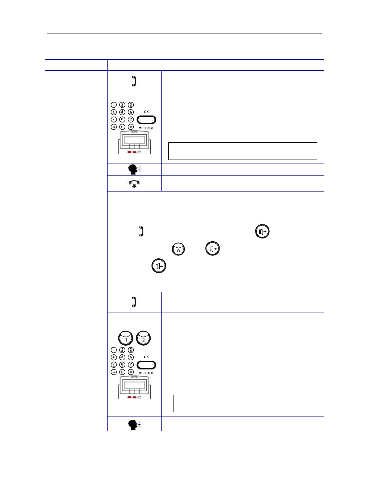
Basic Call Features
Operation Description
1. Pick-up the handset. You will hear dial tone
played.
2. Use the keypad to dial the phone number. Press
OK key or “Dial” softkey to dial out immediately,
or wait for a while (Dial Timeout setting) for
auto-ending the dial. Phone will send out the
dialed number to IG6600. IG6600 will route the
call to destination.
Note: You could use the “Backsp” softkey to
delete the last digit.
3. Start talking to called party.
4. On-hook the handset when your conversation is
over.
Making a Call
There are three mode to establish a call for this IP phone, handset
mode, hands-free mode and headset mode. In this manual, only
handset mode is used for example. In the following features, you can
replace to hands-free mode by pressing key or headset
mode by pressing and key. When the conversation is
over, press key again to release call. For headset mode,
please prepare a headset first.
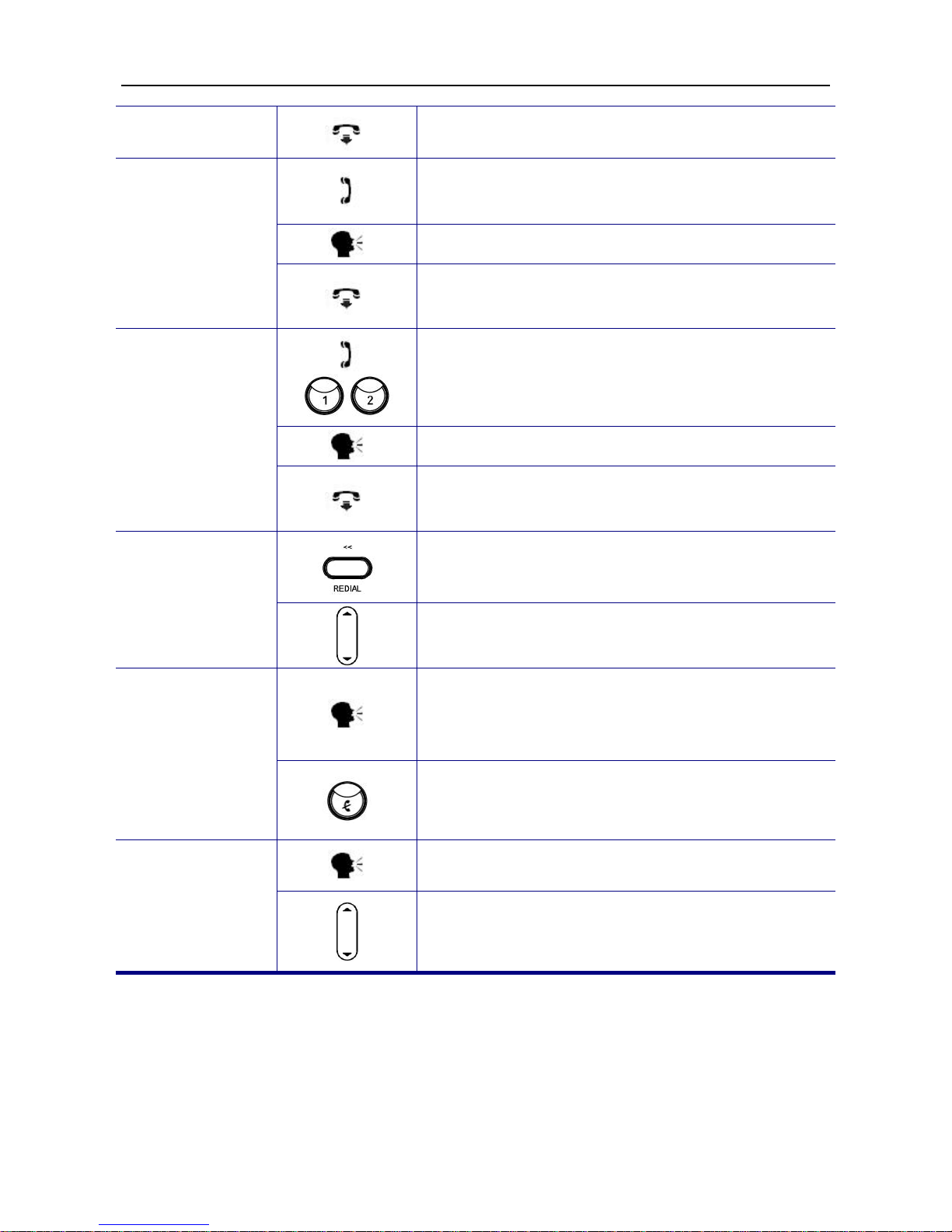
1. Pick-up the handset. You will hear dial tone
played.
2. Press the line key. The LED of line key will light
up and the specific trunk line will be engaged.
Use the keypad to dial the target phone number.
Press OK key to dial out immediately or wait for
a while (Dial Timeout setting) for auto-ending
the dial.
3. User can also dial the PSTN or IP trunk access
number which the IG6600 registered. For
detail about IP and PSTN trunk number, refer to
IG6600’s manual.
Note: You could use the “Backsp” softkey to
delete the last digit.
Making a Call via
Specific Trunk
4. Start talking to called party.
Page 19
IP2032 ADMINISTRATOR’S MANUAL
19
5. On-hook the handset when your conversation is
over.
1. Pick-up the handset while hearing phone’s
ringing.
2. Start talking to caller party.
Receiving a Call
3. On-hook the handset when your conversation is
over.
1. While getting an incoming call from a specific
trunk, the relative line key LED will flash and the
phone rings. You can pick-up the handset or
press the relative line key to receive the call.
2. Start talking to caller party.
Receiving a Call
via Specific
Trunk
3. On-hook the handset when your conversation is
over.
1. Press the REDIAL key, the LCD will show last 10
dialed records.
Last Number
Redial
2. Use volume control key to select a dialed call
and press “Dial” softkey to redial.
1. While being engaged in a conversation
(handset, headset or hands-free mode), you
could mute the microphone by pressing the
MUTE key.
Mute the
Microphone
2. The LED of the MUTE button will light up. At this
moment, the user may speak freely, the outside
party will not hear anything.
1. During a conversation, if the voice volume is too
low or too high, you may adjust it.
Adjust the Voice
Volume During a
Conversation
2. Press the volume control key to adjust the
volume.
Page 20

IP2032 ADMINISTRATOR’S MANUAL
20
Call Record
Operation Description
1. Press the MENU key.
Call Record
2. Use the navigation key to select the Call
Record item. Press OK key to validate the
selection.
Dialed Calls
3. Select the Dialed Calls item and validate with
the OK key.
Review Dialed
Calls
4. Use the navigation key to review the dialed
calls. You may choose to redial the number
(using the “Dial” softkey). Press the “Del”
softkey to delete the selected record. Press the
“Cancel” softkey to exit the menu.
1. Press the MENU key.
Call Record
2. Use the navigation key to select the Call
Record item. Press OK key to validate the
selection.
Received
Calls
3. Select the Received Calls item and validate
with the OK key.
Review Received
Calls
4. Use the navigation key to review the received
calls. You may choose to redial the number
(using the “Dial” softkey). Press the “Del”
softkey to delete the selected record. Press the
“Cancel” softkey to exit the menu.
1. Press the MENU key.
Review Missed
Calls
Call Record
2. Use the navigation key to select the Call
Record item. Press OK key to validate the
selection.
Page 21

IP2032 ADMINISTRATOR’S MANUAL
21
Missed Calls
3. Select the Missed Calls item and validate with
the OK key.
4. Use the navigation key to review the missed
calls. You may choose to redial the number
(using the “Dial” softkey). Press the “Del”
softkey to delete the selected record. Press the
“Cancel” softkey to exit the menu.
Page 22

IP2032 ADMINISTRATOR’S MANUAL
22
Information about the IP2032
You may view all related information about the IP2032 through the LCD menu. This may
give you, for example, the current network settings of the IP2032.
Operation Description
1. Press the MENU key.
Info
2. Use the navigation key to select the Info item
and validate with the OK key.
View Information
about the IP2032
3. Use the navigation key to choose the
information you would like to review.
The following information can be reviewed from the LCD screen of your IP2032:
Model Name
Firmware Number
MAC Address
Network Type
IP Address
Subnet Mask
Default Gateway
DNS Server
Page 23

IP2032 ADMINISTRATOR’S MANUAL
23
5. Advanced Operations
Network Settings
The default network settings are the following:
Default IP address/ Subnet Mask: Depend on DHCP server
Default Gateway: Depend on DHCP server
Default DNS: Depend on DHCP server
Default Administrator’s Username of Web: admin
Default Administrator’s Password of Web: 1234
If you need to change these default settings, please refer to the following instructions.
Operation Description
1. Press the MENU key.
Admin
2. Use the navigation key to select the Admin
item. Press ENTER key to validate the
selection. Type the administrator’s password to
get into Admin menu.
Network
3. Use the navigation key to select the Network
item. Press ENTER key to validate the
selection. The LCD displays the Network
Settings menu.
Network Type
4. Select the Network Type item and press
ENTER key.
Static IP
5. Use the navigation key to choose Static IP type
and press ENTER key to validate.
Static IP
6. Go to previous menu, choose Static IP item and
press ENTER key.
Static IP Address
IP Address,
Subnet Mask,
Default Gateway,
DNS
7. There are IP Address, Subnet Mask, Default
Gateway, and DNS items for user to configure.
Page 24

IP2032 ADMINISTRATOR’S MANUAL
24
8. Use the keypad to enter the IP address, subnet
mask, default gateway, or DNS of your IP
phone. Use the * key for representing a dot .
Press ENTER key to validate the entered
value.
Note: You could use the “Backsp” softkey to
delete the last character.
You must reboot the phone to validate the network parameter
changing.
1. Press the MENU key.
Admin
2. Use the navigation key to select the Admin
item. Press ENTER key to validate the
selection. Type the administrator’s password to
get into Admin menu.
Network
3. Use the navigation key to select the Network
item. Press ENTER key to validate the
selection. The LCD displays the Network
Settings menu.
Network Type
4. Select the Network Type item and press
ENTER key.
DHCP
5. Use the navigation key to choose DHCP type
and press ENTER key to validate.
Dynamic IP
Address (DHCP)
You must reboot the phone to validate the network parameter
changing.
1. Press the MENU key.
Admin
2. Use the navigation key to select the Admin
item. Press ENTER key to validate the
selection. Type the administrator’s password to
get into Admin menu.
PPPoE
Network
3. Use the navigation key to select the Network
item. Press ENTER key to validate the
selection. The LCD displays the Network
Settings menu.
Page 25

IP2032 ADMINISTRATOR’S MANUAL
25
Network Type
4. Select the Network Type item and press
ENTER key.
PPPoE
5. Use the navigation key to choose PPPoE type
and press ENTER key to validate.
PPPoE
6. Go to previous menu, choose PPPoE item and
press ENTER key.
Username
7. Choose Username item and press ENTER key.
8. Use the keypad to enter correct PPPoE
username for PPPoE mode. Press ENTER key
to validate the input.
Note: You could use the “Backsp” softkey to
delete the last character.
Password
9. Go to previous menu, choose Password item
and press ENTER key.
10. Use the keypad to enter correct PPPoE
password for PPPoE mode. Press ENTER key
to validate the input.
Note: You could use the “Backsp” softkey to
delete the last character.
You must reboot the phone to validate the network parameter
changing.
Page 26

IP2032 ADMINISTRATOR’S MANUAL
26
Advanced Call Operations
Operation Description
1. While being engaged in a conversation, you
may hold a call.
2. Press HOLD key to hold the call.
3. To resume a held call, simply press the HOLD
key again.
Call Hold
4. If a trunk line call is held, you can also press the
line key to resume the trunk line call.
1. While being engaged in a conversation, you
may invite another party to join using the 3-way
conference call feature. To achieve this, press
the HOLD key to hold the first call. IP2032 will
automatically switch to another channel.
2. Use the keypad to dial the phone number.
Press OK key to validate, the IP phone will call
out the other party.
3. You can talk with the second party prior to let
him/her join the conference.
3-Way
Conference Call
4. When you are ready to make the conference,
press the CONFERENCE key. The LCD screen
will show “CONFERENCE” that the two calls
are in a conference.
1. While being engaged in a conversation, press
the TRANSFER key. The phone prompts you to
enter the phone number which you would like to
transfer the call to.
2. Use the keypad to dial the phone number.
Press OK key to validate, the IP phone will
transfer the call to other party.
Call Transfer
(Blind Transfer)
3. You can hang up the handset now. The call has
already been transferred.
Page 27

IP2032 ADMINISTRATOR’S MANUAL
27
1. While being engaged in a conversation, hold
the call by pressing the HOLD key. IP2032 will
automatically switch to another channel.
2. Use the keypad to dial the phone number.
Press OK key to validate, the IP phone will call
out the other party.
3. You can talk with the transfer target prior to
transfer the call.
4. When you are ready to transfer the call, press
the TRANSFER key.
Call Transfer
(Attended
Transfer)
5. You can hang up the phone now. The call has
already been transferred.
Page 28

IP2032 ADMINISTRATOR’S MANUAL
28
Phonebook
The phonebook feature let’s you store a list of phone numbers. (For IP2032, it could be
stored up to 200 entries)
Operation Description
Phone Book
1. Press the MENU key.
2. Use the navigation key to select the Phone
Book item and press OK key.
3. Or just press PHONEBOOK key to enter
phonebook menu.
Dial
4. To browse the phonebook data, select Dial item
and press OK key. Then use navigation key to
browse all phonebook data.
Phonebook
(Browse and
Dial a Number)
5. When browsing certain phonebook data, press
“Dial” softkey to dial out the phonebook number.
Press “Cancel” softkey to exit the phonebook
menu.
Phone Book
1. Press the MENU key.
2. Use the navigation key to select the Phone
Book item and press OK key.
3. Or just press PHONEBOOK key to enter
phonebook menu.
Edit
4. Select Edit item and press OK key. Then use
navigation key to browse all phonebook data.
Phonebook
(Add or Edit a
Number)
5. When browsing certain phonebook data, press
“Edit” softkey to add or edit. There are 3 items
for user to add or edit, Name, Number and Ring
Type.
Page 29

IP2032 ADMINISTRATOR’S MANUAL
29
Phone Book
1. Press the MENU key.
2. Use the navigation key to select the Phone
Book item and press OK key.
3. Or just press PHONEBOOK key to enter
phonebook menu.
Delete
4. Select Delete item and press OK key. Then use
navigation key to browse all phonebook data.
Phonebook
(Delete a
Number)
5. When browsing certain phonebook data, press
“Del” softkey to delete.
Page 30

IP2032 ADMINISTRATOR’S MANUAL
30
Speed Dialing
The Speed Dialing feature let’s you store a list of 10 phone numbers that you can access
easily using a Speed Dialing number from 0 to 9.
Operation Description
1. Press the MENU key.
Speed Dialing
2. Use the navigation key to select the Speed
Dialing item and press OK key. The LCD
screen prompts you to enter a number between
0 and 9.
3. You may enter the desired number directly
using the keypad and press OK key to validate,
or use the navigation key to browse all the
Speed Dialing numbers.
Speed Dialing
(Add, Edit, or
Delete a
Number)
If you want to add a new number, find an
empty position, then using keypad to enter a
number. Press OK key to validate.
If you want to edit an existing number, find the
number you would like to edit. Use the
“Backsp” softkey to clear the number and use
keypad to enter a new number. Press OK key
to validate.
1. Pick up the handset.
Dial a Speed
Dialing Number
2. Press the “SPD” (Speed Dialing) softkey. Then
enter a SPD number between 0 and 9. The
corresponding phone number will be dialed out.
Page 31

IP2032 ADMINISTRATOR’S MANUAL
31
Blocking List
The IP2032 provides the possibility to block calls for a specific Caller ID. You can input at
most 10 blocking entries.
Operation Description
1. Press the MENU key.
Line
2. Use the navigation key to select the Line item,
press OK key to validate.
Blocking List
3. Use the navigation key to select the Blocking
List item to enter the Caller Blocking settings
menu. The LCD screen prompts you to enter a
number between 0 and 9.
4. You may enter the desired number directly
using the keypad or use the navigation key to
browse all the blocked Caller ID.
Caller Blocking
(Add, Edit, or
Delete a
Number)
If you want to add a new number, find an
empty position, then using keypad to enter a
number. Press OK key to validate.
If you want to edit an existing number, find the
number you would like to edit. Use the
“Backsp” softkey to clear the number and use
keypad to enter a new number. Press OK key
to validate.
Page 32

IP2032 ADMINISTRATOR’S MANUAL
32
Call and Phone Management
Operation Description
1. Press the MENU key.
Line
2. Use the navigation key to select the Line item,
press OK key to validate.
Call Forward
3. Use the navigation key to select the Call
Forward item and press the OK key to validate
the selection. Select the next item according to
the type of call forward (Always Forward, Busy
Forward, No Answer Forward or DND forward)
you would like to activate.
Status
4. Choose the Status item to turn On/Off the call
forwarding feature. Select On or Off then press
the OK key to validate.
Forward Number
5. Select the Forward Number item to input the
phone number you wish to forward the calls to.
No Answer
Forward
6. For No Answer Forward item, there is one
additional item “No Answer Time” for user to
set. If the phone doesn’t answer the call after
this time, the call will be forwarded to the
destination. (Default value is 15 seconds)
Call Forward
Note: It is possible to activate different kinds of call forward at the same
time. Ex: No Answer forward + Busy Forward, etc.
You can use this function to auto answer all incoming call when you are
busy on something and hope the call can be received automatically.
1. Press the MENU key.
Auto Answer
2. Use the navigation key to select the Auto
Answer item and press OK key.
Auto Answer
3. Use the navigation key to choose to turn On or
Off and press OK key to validate.
Page 33

IP2032 ADMINISTRATOR’S MANUAL
33
DND means “Do Not Disturb”. You can enable this function if you don’t
want any incoming call to disturb your work. And all incoming call will
get busy tone when they make call to your phone number.
1. Press the MENU key.
DND
2. Use the navigation key to select the DND item
and press OK key.
3. Use the navigation key to choose to turn On or
Off the DND feature and press OK key to
validate. While enabling DND function, it shows
"DND" on the LCD at idle state.
DND
Note: If both DND and Call Forward are turned on, the priority will be
DND Forward > Always Forward > Busy Forward or No Answer
Forward.
Page 34

IP2032 ADMINISTRATOR’S MANUAL
34
6. Web Configuration
Login Information
The default network settings are the following:
Default IP address / Subnet Mask: Depend on DHCP server
Default Gateway: Depend on DHCP server
Default DNS: Depend on DHCP server
Default Administrator’s Username of Web: admin
Default Administrator’s Password of Web: 1234
Default User’s Username of Web: user
Default User’s Password of Web: 1111
There are two modes to access the IP phone’s webpage: Administrator and User mode.
Here lists several differences between two modes:
1. There is no Network page for user mode.
2. There is no SW upgrade page for user mode.
3. In Phone page of user mode, the handset/handsfree/headset Mic and all voice
parameter items are hidden.
4. For user mode, most of SIP settings are hidden, only Call Forwarding/Caller Blocking
Settings are kept for user to set.
5. In System page of user mode, only user’s password, time settings and phone reboot are
kept for user to set.
Accessing the phone through web browser, just simply enter the “http://phone-ip” in the
location field of the browser. If you are not sure about the IP address of the phone, you can
examine the current IP address through phone’s menu. (Press MENU key, select item “5.
Info”, use navigation key to check the IP address)
Page 35

IP2032 ADMINISTRATOR’S MANUAL
35
Press ENTER key to validate, the above dialog box will pop up and prompt you to provide
the username and password in order to prevent unauthorized user accessing the phone.
Please input the username and password then press OK button to enter phone’s webpage.
Page 36

IP2032 ADMINISTRATOR’S MANUAL
36
Configuration Pages
Information Page
The following is the default page you will see when you login to the phone’s webpage.
In this page, it shows Network/Product information and Line status.
Page 37

37
Network Page
Network:
Network Type
Select the network type. There are three types: DHCP, S
tatic
IP, or PPPoE.
Time Server
SNTP (Simple Network Time Protocol) server.
Phone will
sync correct time from the server according to phone’
s time
zone setting (In “System” page).
IP Address
Static IP address.
Subnet Mask
Static Subnet Mask.
Default Gateway
Static Default Gateway.
Primary DNS
Static Primary DNS.
Secondary DNS
Static Secondary DNS.
Third DNS
Static Third DNS.
PPPoE Username
Username for PPPoE mode.
PPPoE Password
Password for PPPoE mode.
The Primary/Secondary/Third DNS, Subnet Mask, and Default Gateway are used for Static
IP mode, not for DHCP/PPPoE mode.
It is necessary to reboot the phone after you change the above network related items.
Press “Save Settings” button first, then go to “System” page and press “Reboot” button to
restart the phone.
QoS Settings:
DSCP for RTP
Select Differentiated Services Code Point (DSCP) for RTP.
DSCP for SIP
Select Differentiated Services Code Point (DSCP) for SIP.
Buttons:
Save Settings
Save changes in this page to the phone.
Page 38

IP2032 ADMINISTRATOR’S MANUAL
38
Cancel
Discard all changes in this page.
Page 39

IP2032 ADMINISTRATOR’S MANUAL
39
Phone Page
Volume Control:
Field Name Function
Handset Mic
Select the volume level of handset microphone.
Handset Speaker
Select the volume level of handset speaker.
Handsfree Mic
Select the volume level of hands-free microphone.
Handsfree Speaker
Select the volume level of hands-free speaker.
Headset Mic
Select the volume level of headset microphone.
Headset Speaker
Select the volume level of headset speaker.
Ring Volume
Select the volume level of ring.
Page 40

IP2032 ADMINISTRATOR’S MANUAL
40
Tone/Ring Selection:
Tone Type
Select the tone type for country. There are 11 tone types
for
selection.
Ring Type
Select the ring type. There are10 ring types for selection.
Voice Parameters:
Enable Echo Canceller
Turn on the Echo Cancellation function.
Enable VAD+CNG
Turn on VAD (Voice Activity Detection) and CNG
(Comfortable Noise Generation) function.
Enable Silence
Suppression
Turn on the Silence Suppression function.
Phone Features:
Enable Auto Answer
Turn on Auto Answer function.
When it is enabled, phone will
pick up the call automatically.
Enable DND
Turn on “Do Not Disturb” function. When it is enabled,
all
incoming call will get busy tone when they make call to this
phone number.
User can also press *4 (feature access code)
to enable DND
function.
Enable CLIP
Turn on the CLIP (Calling Line Identity Presence
). The caller
ID of incoming call will show on LCD.
Enable CLIR
Turn on the CLIR (Calling Line Identity Restriction). It’
s used
to hide you number to called party.
Enable Call Waiting
When Call Waiting function is enabled and user is in talk
state, phone can allow other inc
oming calls. It flashes the
line key LED and Call Waiting Tone (If Call Waiting Tone is
enabled) to indicate user. If it’
s disabled, when user is in talk
state, other incoming caller will get busy tone.
User can also press *98 (feature access code) to enab
le Call
Waiting function.
Enable Call Waiting Tone
Turn on the Call Waiting Tone function. At talk state, a
beep
tone will indicate user every 10 seconds when another call
is
ringing in.
Enable Hold Reminder
Turn on the Hold Reminder function.
Hold Reminder Time (sec)
When a call is held, phone will remind user with
a beep tone
every this time period.
Dial Timeout (sec)
Set the timeout to automatically end dialing.
Speed Dialing Settings:
Speed Dialing Entry 0~9
There are 10 speed dialing entries for user to set.
Line Keys:
Page 41

IP2032 ADMINISTRATOR’S MANUAL
41
Line Key Type 1~2
There are 4 types could be chosen: None, Line
, Feature Key
and Call Park
. Phone will do the relative function when user
pressing related line key.
Feature Key String 1~2
The string will be executed when the line
key type is set to
“Feature Key”. When “Call Park”
is chose, the string will be
assigned value automatically.
Buttons:
Save Settings
Save changes in this page to the phone.
Cancel
Discard all changes in this page.
Page 42

42
SW Upgrade Page
HTTP Upgrade:
Field Name Function
Software File
Select desired software and press Update button to upgrade
software.
Configuration File
Select the desired configuration file and press Update
button
to restore the settings. Press Backup button
to save the
configuration file on your PC.
Phonebook File
Select desired phonebook file and press Update button
to
update. Press Backup button to save the phonebook file on
your PC.
The upgrade process will start. It needs 2 minutes to finish, please do not turn off the power
at this time. After updating successfully, the phone will reboot automatically.
TFTP/FTP Upgrade:
Server Type
Select the Server Type. (TFTP or FTP)
Server IP Address
IP address of TFTP or FTP Server.
Files Directory
Files directory where the software, confi
guration file, or
phonebook file located.
Server User Name
Username of the account on the server.
User Password
Password of the account on the server.
Software File
Software file name on the server.
Configuration File
Configuration file name on the server.
Phonebook File
Phonebook file name on the server.
Page 43

IP2032 ADMINISTRATOR’S MANUAL
43
You can also use TFTP or FTP server to update the software, configuration file, or
phonebook file. First, fill the correct file name which you desire to update. Second, press
“Save Settings” button to save. Finally, press relative “Update” button, the update process
will start.
Buttons:
Save Settings
Save changes in this page to the phone.
Cancel
Discard all changes in this page.
Note: If there are errors while you updating the software and the phone can’t work. Please
press the key when phone just power on. Then you can see the hint on LCD. Set
your TFTP server’s IP to “192.168.1.11” and rename the correct software to “app.bin.gz”.
After pressing key, the phone will automatically update the software named
app.bin.gz from fixed IP: 192.168.1.11.
Page 44

IP2032 ADMINISTRATOR’S MANUAL
44
SIP Page
SIP Proxy Server:
Server Mode
Different server mode could be set. There are two
server
mode supported: Normal and IG6600.
SIP Proxy Server
Set SIP proxy server.
Outbound Proxy Server
Set SIP outbound proxy server.
Server Port
Set SIP proxy service port.
SIP Secondary Proxy
Server
Set SIP secondary proxy server.
SIP Surviving Proxy
Server
Set SIP surviving proxy server.
SIP Registrar Server:
Registrar Server
Set SIP registrar server.
Registrar Outbound
Server
Set SIP registrar outbound server.
Registrar Server Port
Set SIP registrar port.
Registrar Expire Time
(sec)
Set SIP registrar expire time.
Subscriber Information:
Page 45

IP2032 ADMINISTRATOR’S MANUAL
45
Phone Number
Set the phone number.
Display Name
Set the display name on LCD.
Authorized ID
Set the authorized ID for SIP registration.
Authorized Password
Set the authorized password for SIP registration.
End Dial on #
Enable # key to end dialing.
DTMF Type
Select the way to send DTMF through in-band or out- band
mode (RFC2833/SIP-INFO).
RFC2833 Payload
Set the RFC2833 payload number.
Session Timer:
Enable Session Timer
Turn on the session t
imer. When a session is established,
phone will resend INVITE packets every half of this time for
preventing from packet lost. The re-
INVITES ensure that
active sessions stay active and completed sessions are
terminated.
Session Expires
Set expire time for session.
MIN SE
Set minimum session expiration time. It will notify
server the
minimum expiration time that you accepted in negotiation
state. It is conveyed in the Min-
SE header in the initial
INVITE request.
Page 46

IP2032 ADMINISTRATOR’S MANUAL
46
Optional SIP Header:
Optional Header 1
Set value for SIP optional header 1.
Optional Header 2
Set value for SIP optional header 2.
RTP Parameters:
RTP Port Base
Set port base for RTP (Real-time Transport Protocol).
Enable Statistic
Enable statistic RTP server.
Statistic Server
Set statistic server.
Statistic Port
Set statistic port.
Codec Settings:
G.711u-law/a-law, G.729,
G.723.1
Select the codec priority for RTP communications.
G.723.1 Bit Rate
Select the bit rate of codec G.723.1.
Packet Time
Select the relative packet time.
Page 47

IP2032 ADMINISTRATOR’S MANUAL
47
NAT Settings:
NAT Type
Select NAT type. There are 4 types for user to select, STUN,
SIP PING, Port Mapping, and UDP Heartbeat.
SIP PING Interval Time
(ms)
Set the SIP PING frequency.
STUN Server IP
Set STUN server IP address.
STUN Server Port
Set STUN server port.
Extern Router IP
Set external router address for port mapping.
Extern Signal Port
Set external SIP signaling port for port mapping.
Extern RTP Port Base
Set external RTP port base for port mapping.
Call Forwarding Settings:
Always Call Forwarding;
Always Forward
Destination
Turn on the always call forwarding function, the right
side is
where the call will be forwarded to. User can also press *21 +
(Forward Destination) to enable this function.
Busy Call Forwarding;
Busy Forward
Destination
Turn on the busy call forwarding function,
the right side is
where the call will be forwarded to. User can also press *22 +
(Forward Destination) to enable this function.
No Answer Call
Forwarding;
No Answer Forward
Destination
Turn on the no answer call forwarding function, the right
side
is where the call will be forwarded to.
User can also press
*23 + Ext No + * + (No Answer Time) to enable this function.
No Answer Timeout (sec)
Set the timeout for No Answer Call Forwarding.
DND Call Forwarding ;
DND Forward Destination
Turn on the DND forwarding function
, the right side is where
the call will be forwarded to. User can also press *24 +
(Forward Destination) to enable this function.
Page 48

IP2032 ADMINISTRATOR’S MANUAL
48
Caller Blocking Settings:
Enable Block Anonymous
Call
Turn on to block the incoming call without Display Name.
Caller Blocking Entry 0~9
There are 10 blocking entries for user to set. When t
he caller
ID of the incoming call matches a certain blocking entry, the
call will be blocked. The remote party will hear busy tone.
Prefix Entry Settings:
Prefix Entry Type,
Pattern, or Replace
If the “Prefix Entry Type” is “Replace” mode, the “Prefix En
try
Pattern”
will be replaced by the “Prefix Entry Replace”. If the
“Prefix Entry Type” is “Add” mode, the “Prefix Entry Replace”
will be added behind
the “Prefix Entry Pattern”. For example,
Page 49

IP2032 ADMINISTRATOR’S MANUAL
49
the “Prefix Entry Pattern” is 220 and the “Prefix Entry
Replace” is 210. When you dial 220 with
keyboard, the
phone will dial 210 for “replace” mode or 220210 for
“Add”
mode.
Dial Plan:
Dial Plan
Outgoing call which fit for the dial plan rule will be called out
immediately, without waiting the dial timeout. It is co
nvenient
for users to make call quickly. There are several kinds of
settings for dial plan: 1. “x”
means any single digit from 0~9.
2. “[digit-digit]” means a valid range for a certain
number
position. 3. [digits] means acceptable numbers for a certain
number position. 4. “|”
is used for separate different dial plan
items. For example, set dial plan as “60xx|30[6-9]|10[45]”
, if
user dial 6000~6099, 306, 307, 308, 309, 104, and 105, IP
phone will dial out it immediately. Otherwise, dial out the
number after dial timeout.
Buttons:
Save Settings
Save changes in this page to the phone.
Cancel
Discard all changes in this page.
Page 50

IP2032 ADMINISTRATOR’S MANUAL
50
System Page
Admin Settings:
Field Name Function
Administrator Name
The administrator username to login phone’s webpage.
Administrator Password
The administrator password to login phone’s webpage.
User Name
The user username to login phone’s webpage.
User Password
The user password to login phone’s webpage.
Enable Log Server
Turn on the log server.
Log Level
Select log level.
System Log Address
Set IP address for system log server.
System Log Port
Set port for system log server.
System Language
Set system language.
The user name is not allowed to the same as administrator name. The administrator’s and
user’s name should be set at least 1 character, not allowed to be null. The administrator’s
and user’s password should be set at least 4 characters. When changing password in
phone’s config menu, less than 4 characters will be discard, not be saved.
Page 51

IP2032 ADMINISTRATOR’S MANUAL
51
The IP2032 provides System Log function. The administrator could assign IP address and
port for system log server. There are 8 log levels for administrator to select.
Time Settings:
Auto DST
Turn on the auto DST (Daylight Saving Time) function.
Daylight Saving Time
Three time shifts could be set, -1, 0, and +1.
Starts on
Start time for DST.
Ends on
End time for DST.
Time Format
USA 24_HOUR, USA 12_HOUR, European 24_HOUR, and
European 12_HOUR.
Time Zone
Set time zone.
Reboot Phone:
Reboot Phone
Reboot this IP Phone.
Reset to Default:
Reset Configuration
Reset Configuration to factory default.
Reset Phonebook
Clear all Phonebook data.
Reset All
Reset all data to default including Configuration,
Call
Records, and Phonebook data.
Diagnostics:
Download System Log
Press to download system log.
View SIP Message
Press to view SIP messages.
Buttons:
Save Settings
Save changes in this page to the phone.
Cancel
Discard all changes in this page.
Page 52

IP2032 ADMINISTRATOR’S MANUAL
52
Phonebook
This page lets you configure phonebook data of your phone. You may:
Edit up to 200 entries. Each page will just show 20 entries.
Dial a phone number directly from this webpage.
Phonebook Entry:
Field Name Function
User Name
Name of your contact.
Phone Number
Phone number or SIP URI of your contact.
Ring Type
Select particular ring type for each entry.
To call your contact, simply click the corresponding Dial button and it will show the following
dialog box (for example, if you click first entry to call out, the result will be the following):
Page 53

IP2032 ADMINISTRATOR’S MANUAL
53
Then press the “Dial” button in order to start dialing. Phone will dial out corresponding
number automatically.
Page 54

IP2032 ADMINISTRATOR’S MANUAL
54
7. Features & Specifications
With highly integrated chip and sophisticated design, this IP2032 offers a variety of features.
And it can provide high performance, reliable and quality voice communication for the users.
The hardware specifications are list as follows for your reference.
Main Unit
-Dimension: 180 * 195 * 105 mm.
-Plastic material: ABS type.
-Support 2 angles (one is with stand and the other is without stand).
-Can be mounted onto the wall with the stand.
-Support detachable handset and curled cord.
LAN and PC Ports
-Integrated 2 ports Ethernet switch.
-IEEE 802.3 10BaseT / 802.3u 100BaseTx compliant.
-Auto-negotiation with link speed and full/half duplex mode.
-Auto MDI/MDIX for both downlink and uplink auto-swapping.
-Support QoS IEEE 802.1p voice priority function.
Power Supply
-Input: 5VDC/2A power adapter.
-Support PoE (Power over Ethernet), IEEE 802.3af Device - Class 2 (7W).
Voice Handling
-Supports multiple Audio Codecs: G.711 a-law/ μ-law, G.729, G.723.1 (5.3Kbps/6.3Kbps).
-Supports VAD (Voice Activity Detection) and CNG (Comfort Noise Generation).
-Volume adjustable for handset, headset, hands-free and ring.
-Support G.165 16ms line Echo Cancellation.
-Adaptive Jitter Buffering function supported.
-Hands-free talking supported.
-Support multiple calls and multiple lines appearance.
Tone Function:
-DTMF tone generation.
-Side tone and good voice quality supported.
-Out-bound DTMF relay (RFC2833/SIP-INFO) support.
-Local tone support (Dial, Ring, Ring back, Busy and related tones).
Feature Access Codes:
Page 55

IP2032 ADMINISTRATOR’S MANUAL
55
The Feature Access Codes are applied between IP2032 and IG6600. It’s used to
activate/deactivate some user-specified functions.
These Feature Access Codes are accepted when the phone is at idle state.
Direct Call Forward
Forward all of the calls without regard to the extension status.
To Activate
*21 + Ext No
*21 + * + (phone’s password) + * + (Outside Telephone Number)
To Cancel
**21
Busy Call Forward
Forward the calls if the extension is busy.
To Activate
*22 + Ext No
*22 + * + (phone’s password) + * + (Outside Telephone Number)
To Cancel
**22
No Answer Call Forward
Forward the calls if the extension doesn't answer the call after No Answer Time.
To Activate
*23 + Ext No + * + Time
*23 + * + (phone’s password) + * + (Outside Telephone Number) + * + Time
To Cancel
**23
DND Call Forward
Forward the calls if the extension enables DND.
To Activate
*24 + Destination
To Cancel
**24
Direct Call Forward to Voice Mail Box
Page 56

IP2032 ADMINISTRATOR’S MANUAL
56
Forward all of the calls to its own Voice Mail box.
To Activate
*25
To Cancel
**25
DND (Do Not Disturb)
Extension users can enable DND to stop incoming calls from ringing at their phone.
To Activate
*4
To Cancel
**4
COS Following
It changes the individual COS of the extension temporarily.
*55 + (phone number) + (phone’s password)
Call Back Busy
When called party is busy and hearing busy tone, press “6” to wait them call back.
Pressing “*66” to cancel the function.
To Activate
6
To Cancel
*66
Reset Feature Access Code to Default
IG6600’s extension features can be returned to default setting.
*69 + (phone’s password)
Line Key Programming
To program the line keys as a PSTN, IP Trunk or Trunk Group number.
*70 + (Feature Key number, 1 – 2) + (PSTN, IP Trunk, or Trunk Group number)
Agent Log On/Off
It is used for an extension to log on/off from it’s ICD group.
To Activate (Log On)
Page 57

IP2032 ADMINISTRATOR’S MANUAL
57
*91
To Cancel (Log Off)
**91
Phone Lock/Unlock
You can use the lock feature to prevent unauthorized “trunk calls” that being made from
extension.
To Activate Phone Lock
*97 + (phone’s password)
To Cancel Phone Lock
**97 + (phone’s password)
Call Waiting
If it's enabled, it can allow other incoming calls when phone is in talk state. If it's disabled,
other incoming caller will get busy tone when phone is in talk state.
To Activate
*98
To Cancel
**98
Page Allow/Deny
To allow/deny group paging or all paging.
To Activate Page Deny
*99
To Cancel Page Deny
**99
Page 58

IP2032 ADMINISTRATOR’S MANUAL
58
8. Troubleshooting
Symptom Check & Remedy
No operation
Check if the power adapter is properly connected.
Check if the Ethernet cable is properly connected.
If applicable, check if the PoE (Power over Ethernet)
switch behind the IP phone is set to the right position.
No dial tone
Check if the handset cord is properly connected.
Check if the power adapter is properly connected.
Check network
connection shown
on LCD
Check if the Ethernet cable is properly connected.
Cannot make call
Check the status of your SIP registration or contact
your supplier or ITSP for more information or
assistance.
IP phone cannot
receive any phone
call
Check if the Ethernet cable is properly connected
Check the status of your SIP registration or contact
your supplier or ITSP for more information or
assistance.
Cannot connect to
the configuration
website of the IP
phone
Check if the Ethernet cable is properly connected.
Check the IP address of the IP phone.
Check if your firewall/NAT settings are correct.
Page 59

IP2032 ADMINISTRATOR’S MANUAL
59
9. Glossary
Acronyms
CODEC Coder and Decoder of Voice
CNG Comfort Noise Generation
DHCP Dynamic Host Configuration Protocol
DNS Domain Name Server
DTMF Dual Tone Multiple Frequency
HTTP Hypertext Transfer Protocol
IP Internet Protocol
ISP Internet Service Provider
ITSP IP Telephony Service Provider
LAN Local Area Network
MWI Message Waiting Indication
PoE Power over Ethernet (IEEE802.3af standard)
PPPoE Point-to-point protocol over Ethernet
QoS Quality of Service
NAT Network Address Translation
RTP Real Time Protocol
SIP Session Initiation Protocol
SNTP Simple Network Address Translation
TFTP Trivial File Transfer Protocol
Page 60

IP2032 ADMINISTRATOR’S MANUAL
60
Terminology
10/100BASE-T
It’
s a LAN transmission line specification stipulated by IEEE. Transmission speed
is 10 or 100 Mbps and the modulation technique is base-
band modulation. The
cable uses unshielded twisted pair, similar to
a telephone wire. 10BaseT is an
IEEE standard (802.3) for operating 10 Mbps Ethernet networks (LANs) with
twisted pair cabling and a wiring hub.
Auto answer
In telephone call control: The capability of a machine to answer a ringing
telephone without human intervention.
CODEC
The CODEC (CODER/DECODER) is a standard through which voice information
can be encoded into data or decoded back to voice information. Both a Coder and
Decoder are necessary on both sides of the telephone call since telephone calls
o
ccur simultaneously in both directions. Bandwidth is an extremely important
factor in QOS (Quality of Service). MOS (Mean Opinion Score) is an attempt to
make a quantifiable benchmark of voice quality. Below are examples of the
CODEC, bit rate and mean opi
nion score: G.711 (toll quality) 64K MOS=4.1,
G.726 16K (32K) MOS =3.8, G.729AB (cell phone quality) 8K MOS=3.7.
DHCP
Dynamic Host Configuration Protocol (DHCP):
A utility that enables a server to
dynamically assign IP addresses from a predefined list and
limit their time of use
so that they can be reassigned. Without DHCP, an IT Manager would have to
manually enter in all the IP addresses of all the computers on the network. When
DHCP is used, whenever a computer logs onto the network, it automatically ge
ts
an IP address assigned to it.
Diff-Serv
Differentiated Services: The Diff-
Serv model divides traffic into a small number of
classes to provide quality of service (QoS). One of QoS in internet.
DNS
Domain Name Service (DNS): A server/program that trans
lates URLs to IP
addresses by accessing a database maintained on a collection of Internet
servers. The program works behind the scenes to facilitate surfing the Web with
alpha versus numeric addresses. A DNS server converts a name like
mywebsite.com to a s
eries of numbers like 107.22.55.26. Every website has its
own specific IP address on the Internet.
Typically one or more DNS servers is
located in an IP network.
DTMF
Dual Tone Multi-Frequency (DTMF)
: The type of audio signals generated when
you press the buttons on a touch-tone telephone. Can be used in inbound
(after
voice channel connected) and outbound (before voice
channel connected)
application.
Ethernet
International standard networking technology for wired implementations. Basic
10BaseT networks
offer a bandwidth of about 10 Mbps. Fast Ethernet (100 Mbps)
and Gigabit Ethernet (1000 Mbps) are becoming popular.
G.711
64 kbps PCM half-
duplex codec (high quality, high bandwidth, minimum processor
load)
IP
Internet Protocol (IP) is located at 3rd lay
er of ISO network model. A set of rules
used to send and receive messages at the Internet address level. IP protocol is
widely used in Internet and LAN networks. The purpose is to deliver data between
computing equipment over the network. The protocol is g
enerally effective but
does not guarantee complete and accurate data communications.
Page 61

IP2032 ADMINISTRATOR’S MANUAL
61
IP address
A 32-
bit number that identifies each sender or receiver of information that is sent
across the Internet. An IP address has two parts: an identifier of a partic
ular
network on the Internet and an identifier of the particular device (which can be a
server or a workstation) within that network. A number used to identify the location
of a host device. It is expressed in numeric dot notation (e.g. 202.203.27.31).
MAC address
Media Access Control address (MAC address): It
is a unique identifier assigned to
most network adapters or network interface cards by the manufacturer for
identification, and used in the Media Access Control protocol sub-
layer. It may
also be kno
wn as an Ethernet Hardware Address or physical address. In TCP/IP
networks, the MAC address of a subnet interface can be queried with the IP
address using the Address Resolution Protocol (ARP) for Internet Protocol. On
broadcast networks, such as Ethernet,
the MAC address uniquely identifies each
node and allows frames to be marked for specific hosts. It thus forms the basis of
most of the Link layer (OSI Layer 2) networking upon which upper layer protocols
rely to produce complex, functioning networks.
NAT
Network Address Translation (NAT)
: A network capability that enables a houseful
of computers to dynamically share a single incoming IP address from a dial-
up,
cable or xDSL connection. NAT takes the single incoming IP address and creates
new IP address for each client computer on the network.
Proxy server
Used in larger companies and organizations to improve network operations and
security, a proxy server is able to prevent direct communication between two or
more networks. The proxy server forwards allo
wable data requests to remote
servers and/or responds to data requests directly from stored remote server data.
PSTN
Public Switched Telephone Network (PSTN)
: The worldwide voice telephone
network.
RJ-45
Standard connectors used in Ethernet networks. Ev
en though they look very
similar to standard RJ-11 telephone connectors, RJ-
45 connectors can have up to
eight wires, whereas telephone connectors have only four.
RTP/RTCP
Real-Time Protocol/Real-Time Control Protocol
(RTP/RTCP): IETF specifications
for a
udio and video signal management. Allows applications to synchronize and
spool audio and video information. RTP is specifically concerned with the
dependable transmission of latency-
sensitive traffic across the network and is
involved in using time stampin
g to determine network jitter tolerance and makes
sure that voice packets are arriving in order.
SIP
Session Initiation Protocol (SIP):
A protocol that provides telephony services
similar to H.323, but is less complex and uses fewer resources. SIP is a si
gnaling
protocol for Internet conferencing, telephony, presence, events notification and
instant messaging. SIP is a text-
based protocol, similar to HTTP and SMTP, for
initiating interactive communication sessions between users.
Subnetwork or Subnet
Found
in larger networks, these smaller networks are used to simplify addressing
between numerous computers. Subnets connect to the central network through a
router, hub or gateway. Each individual wireless LAN will probably use the same
subnet for all the local computers it talks to.
TCP/IP
Internet Standard Protocol: The underlying technology behind the Internet and
communications between computers in a network. The first part, TCP, is the
transport part, which matches the size of the messages on either end a
nd
guarantees that the correct message has been received. The IP part is the user's
computer address on a network. Every computer in a TCP/IP network has its own
IP address that is either dynamically assigned at startup or permanently assigned.
Page 62

IP2032 ADMINISTRATOR’S MANUAL
62
All TCP/IP
messages contain the address of the destination network as well as
the address of the destination station. This enables TCP/IP messages to be
transmitted to multiple networks (subnets) within an organization or worldwide.
VAD
Voice Activity Detection (VA
D) helps save bandwidth during calls. Examples:
When you making a VoIP call and your not speaking and your listening, that
silence is still taking up bandwidth during the call. When silence is detected by
VAD software over a predetermined length of time, it
sends silent packets that
inform other VAD enabled systems to stop holding the bandwidth for these empty
packets.
VoIP
Voice Over Internet Protocol: VoIP is based on the principal of transmitting
digitized voice packets over networks. Basically, VoIP c
onsists of converting voice
signals into streams of digi
tal packets and sending those packets of data through
an IP-
constructed network environment. VoIP can work in both LAN (local area
network) and WAN (wide area network) environments for intranetwork or
internetwork communication between VoIP channel users.
Routers and switches
and other special compression protocols direct the packetized voice data to their
destination IP address. VoIP can be less expensive than voice transmission using
standard analog packets over POTS (Plain Old Telephone Service). It allo
ws
telephone calls, faxes, or overhead paging to be transported over an existing
IP
data network topology.
 Loading...