

TECOM Challenger10 TS1016, Challenger10 TS1016T, ChallengerSE TS1016SE, ChallengerLE TS1016LE Installation And Programming Manual
Page 1

Challenger® Series
Installation and Quick
Programming Manual
P/N MAINST-TS1016 • REV 07 • ISS 20AUG15
Page 2

Copyright
©
Trademarks and
patents
The Challenger name and logo are trademarks of
Security
Other trade names used in
registered trademarks of the manufacturers or vendors of the
respective products.
Manufacturer
UTC Fire & Security Australia Pty Ltd t/a Interlogix
A UTC Building & Industrial Systems company
Ground Floor, 10 Ferntree
Agency
compliance
PTC 211 / 13 / 007
Contact information
For contact information, see
N4131
2015 UTC Fire & Security Australia Pty Ltd. All rights reserved.
UTC Fire &
Australia Pty Ltd.
this document may be trademarks or
Place, Notting Hill, VIC, 3168, Australia
www.interlogix.com.au.
Page 3

Content
Important information ......................................................................................... ii
Agency compliance .............................................................................. ii
Limitation of liability .............................................................................. ii
Regulatory requirements for New Zealand ......................................... iii
Preface ................................................................................................................ iv
Product overview ................................................................................................ 1
Product contents .................................................................................. 1
ChallengerSE functionality ................................................................... 2
ChallengerLE functionality ................................................................... 3
Before you begin ................................................................................................. 4
Cabling requirements ........................................................................... 4
System configurations ......................................................................... 8
Installing the control panel ............................................................................... 11
Installation guidelines ........................................................................ 13
Installation procedures ....................................................................... 14
Board details (TS1016, TS1016T, TS1016SE) .................................. 15
Board details (TS1016LE).................................................................. 18
Application notes ............................................................................... 21
Initial programming ........................................................................................... 27
Disarming the system ........................................................................ 27
Accessing the Challenger menu ........................................................ 27
Clearing the memory ......................................................................... 31
Basic programming sequence ........................................................... 32
Working with multi-area systems ....................................................... 33
Default installer PIN ........................................................................... 34
Enabling communications .................................................................. 34
Programming users............................................................................ 37
Firmware upgrade process .............................................................................. 38
Requirements .................................................................................... 38
Getting ready ..................................................................................... 38
Upgrade process ............................................................................... 38
Challenger Series Installation and Quick Programming Manual i
Page 4

Important information
Agency compliance
This product conforms to the standards set by Standards Australia on behalf of
the Australian Communications and Media Authority (ACMA). Enclosure covers
must remain fitted in order to maintain C-Tick compliance.
Limitation of liability
To the maximum extent permitted by applicable law, in no event will Interlogix (a
division of UTC Fire & Security Australia Pty Ltd) be liable for any lost profits or
business opportunities, loss of use, business interruption, loss of data, or any
other indirect, special, incidental, or consequential damages under any theory of
liability, whether based in contract, tort, negligence, product liability, or otherwise.
Because some jurisdictions do not allow the exclusion or limitation of liability for
consequential or incidental damages the preceding limitation may not apply to
you. In any event the total liability of Interlogix shall not exceed the purchase
price of the product. The foregoing limitation will apply to the maximum extent
permitted by applicable law, regardless of whether Interlogix has been advised of
the possibility of such damages and regardless of whether any remedy fails of its
essential purpose.
Installation in accordance with this manual, applicable codes, and the instructions
of the authority having jurisdiction is mandatory.
While every precaution has been taken during the preparation of this manual to
ensure the accuracy of its contents, Interlogix assumes no responsibility for
errors or omissions.
ii Challenger Series Installation and Quick Programming Manual
Page 5

Regulatory requirements for New Zealand
Some parameters required for compliance with Telecom’s Telepermit
requirements are dependent on the equipment (PC) associated with this device.
In order to operate within the limits for compliance with Telecom’s Specifications,
the associated equipment shall be set to ensure that:
• There shall be no more than 10 call attempts to the same number within any
30 minute period for any single manual call initiation.
• The equipment shall go on-hook for a period of not less than 30 seconds
between the end of one attempt and the beginning of the next attempt.
• Automatic calls to different numbers are spaced such that there is no less
than 5 seconds between the end of one call attempt and the beginning of
another.
• This equipment shall not be set up to make automatic calls to the Telecom
‘111’ Emergency Service.
• The associated equipment shall be set to ensure that calls are answered
between 3 and 30 seconds of receipt of ringing.
Refer to the Challenger Series Programming Manual for details about
programming these parameters.
Challenger Series Installation and Quick Programming Manual iii
Page 6

Preface
This manual applies to the following Challenger Series control panels:
• Challenger10 (model TS1016 with external 16 Volt AC plug pack or model
TS1016T with internal 240 VAC mains transformer).
• ChallengerSE (model TS1016SE) with external 16 Volt AC plug pack. Refer
to “ChallengerSE functionality” on page 2 for more information.
• ChallengerLE (model TS1016LE) with external 16 Volt AC plug pack. Refer to
“ChallengerLE functionality” on page 3 for more information.
The product name “Challenger” will be used for all Challenger Series panels
unless otherwise noted. The term “Challenger Series” does not apply to legacy
products such as Challenger V8.
The Challenger Series Installation and Quick Programming Manual is for
installation technicians to install a Challenger panel.
Refer also to other Challenger manuals in the suite.
• The Challenger Series Programming Manual is for system administrators and
installers who need to manage the Challenger system via its
text-based user interface (in particular the “Install” menu”).
• The Challenger Series Users Manual is suitable for most users of the
Challenger system to perform everyday tasks.
• The Challenger Series Administrators Manual is for users and system
administrators who need to manage the Challenger system via its text-based
user interface (in particular the User menu).
Notes
• The permissions assigned to you may not allow you to do everything
described in this manual. You may not be able to see all menu items
described in this manual.
• A qualified service person, complying with all applicable codes, should
perform all required hardware installation.
iv Challenger Series Installation and Quick Programming Manual
Page 7

Quantity
1
1
1
1
1
1
1
1
1
1
1
1
5
15
10
1
1
1
40
Product overview
Challenger is a scalable intrusion detection and access control system.
Challenger panels use one, and optionally a second, RS-485 data bus (LAN) to
provide continuous polling of remote arming stations (RAS) and data gathering
panels (DGP). These devices extend the system’s intrusion detection and access
control functions.
Refer to the Challenger Series Programming Manual for details.
Product contents
Table 1 below lists the items that are shipped with Challenger control panels.
Table 1: Challenger panel shipping list
Item
Metal enclosure (with four spring standoffs fitted)
Challenger panel board
604 to RJ12 lead line, 1.5 m (not applicable to ChallengerLE)
Challenger Series Administrators Manual
Challenger Series User Manual
Challenger Series Installation and Quick Programming Manual
16 Volt AC plug pack (applies to TS1016, TS1016SE, and TS1016LE)
240 VAC mains transformer, 2A, with mains power cord (applies to TS1016T)
240 VAC terminal block with fuse (applies to TS1016T)
Tamper switch
Tamper switch metal bracket
Ring terminal
M3 x 14 pan head screws
3-way plug-on screw terminal connectors (13 for TS1016LE)
2-way plug-on screw terminal connectors (3 for TS1016LE)
Red battery lead with QC terminal
Black battery lead with QC terminal
1K 1/4 watt resistor
10K 1/4 watt resistors (20 for TS1016LE)
Inspect the package and contents for visible damage. If any components are
damaged or missing, do not use the unit; contact the supplier immediately.
Challenger Series Installation and Quick Programming Manual 1
Page 8

ChallengerSE functionality
User capacity
TS1016SE Challenger Standard Edition (ChallengerSE) panels support 100
users. This capacity can be expanded to 2,000 users via a TS1082 User
Expansion Licence or 65,535 users via a TS1084 Memory Expansion Module.
Note: If a ChallengerSE control panel needs more than 2,000 users, then a
TS1084 Memory Expansion Module must be used in place of the TS1082 User
Licence Module.
Communications ports
When a ChallengerSE control panel is used without being fitted with a
communications module (such as a TS1091 Enhanced Communications
Licence) the ChallengerSE panel’s onboard Ethernet, USB, and RS-232
communications ports are time-limited.
When the ChallengerSE panel is initially powered, defaulted, or is restarted, the
communications ports can be used for 60 minutes. During this time, the top line
of the LCD RAS displays “Remote nn,” (where nn is the number of minutes
remaining, counting down from 60).
When the remote communications session expires, the panel’s communications
ports are deactivated, and the LCD RAS displays as per the programmed
settings.
If you need more than 60 minutes of communication, use the Service menu
option 6 “Management software for 60mins” to restart the timer. (This command
may be used at any time to enable the communications ports for 60 minutes.)
RAS display
You can tell via LCD RAS whether a ChallengerSE panel has modules fitted. Use
Install menu option 11 Version, and then select option 1 Chall. Press [ENTER]
repeatedly to see the panel’s details, including memory type and communications
type.
The displayed memory types are:
• “TIUM” indicates 100 user capacity (ChallengerSE or ChallengerLE default)
• “MIUM” indicates 2000 user capacity (Challenger10 default or ChallengerSE
with TS1082 module fitted)
• “LIUM” indicates 65,535 user capacity (TS1084 module fitted)
The displayed communications types are:
• 60min Comms (ChallengerSE default)
• Full Comms (Challenger10, ChallengerLE default; ChallengerSE with
communications module fitted)
2 Challenger Series Installation and Quick Programming Manual
Page 9

ChallengerLE functionality
TS1016LE Challenger Lite Edition (ChallengerLE) panel capacities differ from
Challenger10 panels in certain respects. Refer to the Challenger Series
Programming Manual, R06 (or later) or the product data sheet for specific details.
The ChallengerLE capacities of note to installers are:
• 100 users (with names)
• 16 areas
• 32 area groups
• 48 inputs (8 onboard, 8 logical, and 32 via DGP)
• 32 relays (outputs)
• 1 RS-485 system LAN
• 16 Remote Arming Stations (RASs)
• 1 Data Gathering Panel (DGP)
• Intelligent Access Controllers (4-Door or 4-Lift Controllers) are not supported
Onboard ports provide connection via IP, RS-232 (or printer), and USB. Plug-on
expanders provide connection via dialler (PSTN) or wireless (3G).
Challenger Series Installation and Quick Programming Manual 3
Page 10

Before you begin
This section contains items that govern the installation of many different
Challenger system devices (including but not limited to the Challenger panel).
When installing a Challenger panel, or any other parts of the system, you need to
be aware of requirements for cabling and earthing, and plan accordingly.
NOTICE! A qualified service person, complying with all applicable codes, should
perform all required hardware installation.
Disclaimer: This manual contains requirements based on Australia and New
Zealand codes. It is not an authoritative reference regarding codes and has not
been reviewed by the responsible authorities. The codes may change and may
not be reflected in this document.
Cabling requirements
This section contains requirements for installers for the application and wiring of
Challenger equipment with respect to:
• System earthing
• RS-485 data cable (LAN) cabling
• Power supply from LAN or from external 12 V supply
System earthing
The following requirements are essential to the reliable operation of the
Challenger system.
• Each device’s GND link (if applicable) must be removed.
• For models TS1016, TS1016SE, or TS1016LE connect the earth conductor
from the 240/16 VAC plug pack earth to the Challenger panel’s earth terminal
(Figure 7 on page 15, item 3 or Figure 9 on page 18, item 3). For model
TS1016T connect the earth conductor from the 240 VAC terminal block to the
Challenger panel’s earth terminal. Do not extend this wire to any device
outside of the enclosure.
• Some Challenger devices have an earth lug (or stud) on the PCB and are
fitted with a link labelled “GND” or “EARTH”. In such cases, the device’s GND
or EARTH link must be removed. When configured correctly, there will be a
resistance value greater than 100 kΩ between the device’s earth lug (or stud),
or power earth terminal (similar to Figure 7 on page 15, item 3), and any “C”
or “0V” terminal on the device.
• Install LAN isolation devices between multiple buildings and maintain
independent earthing systems. For example, use TS0893, TS0894, or
TS0896 Isolation Interface modules to provide electrical isolation and/or to
extend distance.
4 Challenger Series Installation and Quick Programming Manual
Page 11

Earthing of one cabinet containing several devices. All devices designed for
the system have earth connections via metal studs to the metal housing. Take
care that these metal studs have a good connection to bare metal (no paint).
Earthing of panels in a single building. In a single building several cabinets or
devices are earthed. A licensed electrician should check the integrity of the
building earth system.
Earthing of panels in more than one building. If the wiring extends to separate
buildings, use more than one common earth system. Install LAN isolation
devices, such as TS0893, to isolate the system LAN between buildings to protect
the system against differences in earth potential. See Figure 3 on page 9.
Guidelines for retrofitting a Challenger V8 system
When replacing a Challenger V8 panel with a Challenger Series panel in an
existing installation:
• Where used, a device’s GND or EARTH link must be removed (if fitted).
Note: Challenger Series panels do not have a GND link.
• Where 240/16 VAC plug packs are used, connect the earth conductor to the
device’s power earth terminal (similar to Figure 7 on page 15, item 3).
• Connect one end only of the RS-485 data cable shield to a device’s LAN
earth terminal or earth lug (similar to Figure 7 on page 15, item 1).
• All other wiring compliant with Challenger V8 earthing via a Communications
Earth Terminal (CET) may remain unchanged.
Guidelines for new Challenger installations
When installing a Challenger panel in a new installation, follow the wiring
requirements of this manual including:
• Where used, a device’s GND or EARTH link must be removed (if fitted).
Note: Challenger Series panels do not have a GND link.
• Where 240/16 VAC plug packs are used, connect the earth conductor to the
device’s power earth terminal (similar to Figure 7 on page 15, item 3).
• Connect one end only of the RS-485 data cable shield to a device’s LAN
earth terminal or earth lug (similar to Figure 7 on page 15, item 1).
• Connections to building earth via CET are no longer required.
Note: For new installations the earthing and configuration instructions in this
manual supersede all previously-released installation instructions supplied with
other devices (unless otherwise noted).
RS-485 LAN cabling
The cabling requirements for an RS-485 system LAN are:
• Use 2-pair twisted shielded data cable such as Belden 8723.
Challenger Series Installation and Quick Programming Manual 5
Page 12

• In each segment of LAN cabling, connect one end only of the data cable
shield to a device’s LAN earth terminal. Join data cable shields where cable
extends past a device that doesn’t have a LAN earth connection.
• The length of the LAN cable run should not exceed 1.5 km, unless LAN
isolation devices are used to extend the distance.
Power supply to RS-485 LAN devices
Devices on the LAN may be supplied from the panel’s or DGP’s + and – LAN
power terminals. Use an external 12 V power supply (such as TS0073 2 A Power
Supply) when:
• The device is more than 100 m (data cable length) from the panel
• Electrical isolation is required
• More power is needed than can be provided by the LANs
When powering a LAN device from an external 12 V power supply:
• Connect the external power supply’s ‘+’ terminal to the device’s ‘+’ terminal.
Do not connect the power supply + to the LAN +.
• Connect the external power supply’s ‘-’ terminal to the device ‘-’ terminal.
• Connect the LAN cable black wire ‘-’ to the device ‘-’ terminal.
6 Challenger Series Installation and Quick Programming Manual
Page 13
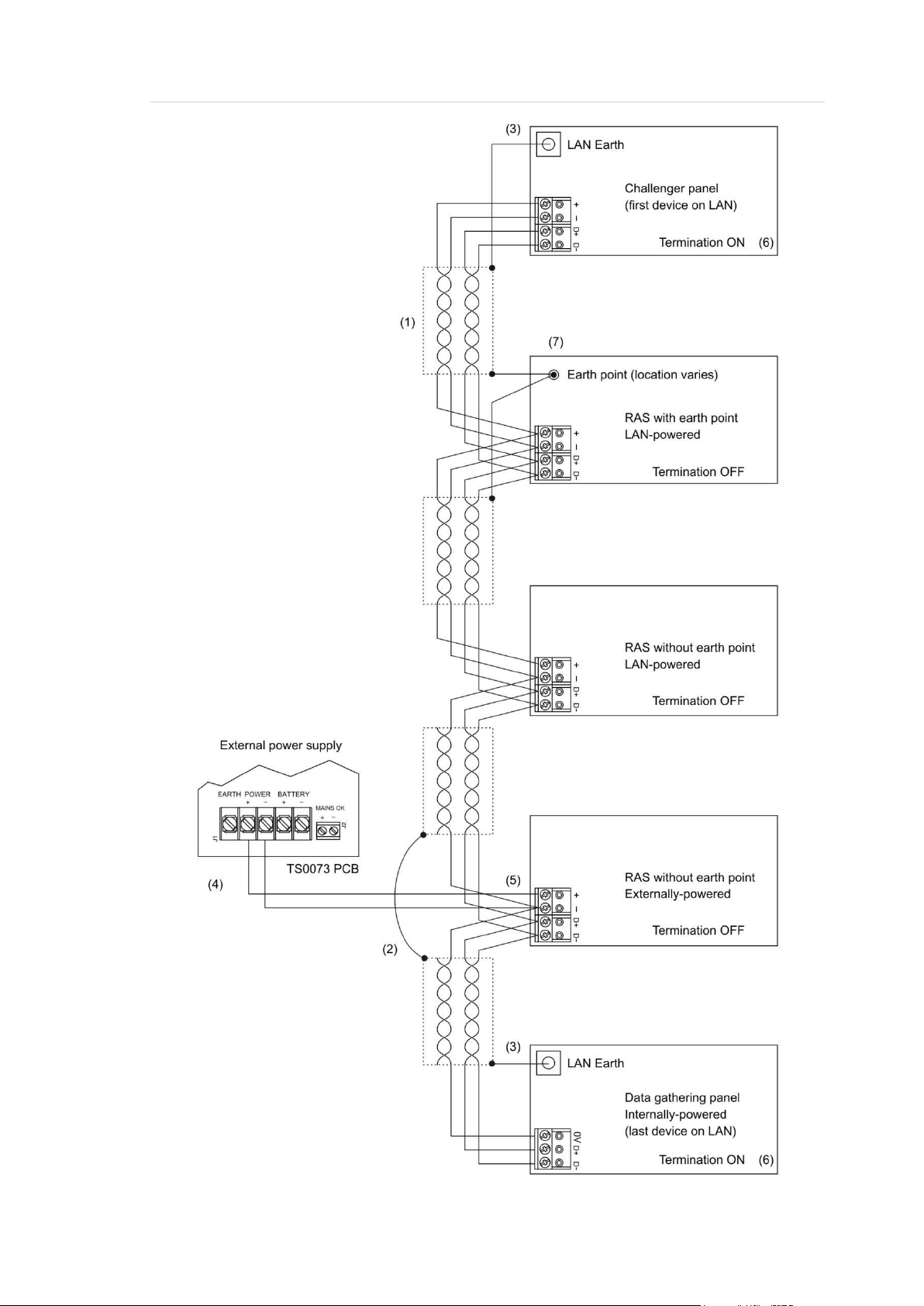
Figure 1: RS-485 LAN 1 or LAN 2 and earth system block diagram
Challenger Series Installation and Quick Programming Manual 7
Page 14

Item
1.
pair twisted shielded data cable such as
2.
data cable shields where cable extends past a device that doesn’t have a LAN earth
3.
4.
5.
6. Terminate the control panel and the most distant device, or the devices at the ends of the
7.
cable shield. Alternatively,
Figure 1 legend
Description
RS-485 LAN cable. We recommend the use of 2-
Belden 8723 for optimal performance.
Join
connection.
In each segment of LAN cabling, connect one end only of the data cable shield to a
device’s LAN earth terminal.
External 12 VDC power supply (if needed).
Do not connect the + from the external 12 VDC power supply to the + of the LAN.
two longest LAN cable runs, as applicable.
The RAS earth point should typically be connected to the data
it may be connected to building electrical earth (for example, if mounting to an earthed
metal fixture).
System configurations
A Challenger LAN may be configured in a variety of ways:
• Straight LAN, where the Challenger panel is at one end of a LAN cable run
• Star LAN, where multiple LAN cable runs are used in a branched
configuration
• Multi-building, where the LAN extends to more than one building
LAN 1 is required and LAN 2 is optional (ChallengerLE has only LAN 1). Each
LAN must be independently configured and terminated.
Straight LAN
In a straight configuration (Figure 1 on page 7), the Challenger panel is at one
end of the LAN cable run and all other devices are connected to the LAN cable.
The termination would be ON for the Challenger panel and for the last device on
the LAN.
Star LAN
In a star configuration, the LAN has at least two branches (Figure 2 on page 9)
optionally connected via a TS0844 Power Distribution Board (see “TS0844
Power Distribution Board” on page 10). The termination would be ON for the two
devices at the ends of the two longest cable runs.
Note: A star LAN configuration may consist of a number of cable runs
(branches). LAN termination should be ON only at the devices at the far ends of
the two longest branches. A star LAN that has multiple branches in excess of 100
m may need to use LAN isolation devices such as TS0893 LAN Isolation
Interface modules to isolate the LAN segments that do not have LAN termination
set to ON.
8 Challenger Series Installation and Quick Programming Manual
Page 15

Item
1.
Figure 2: Star LAN configuration
Multi-building or long-distance LAN cabling
If the RS-485 LAN extends to more than one building, each building must have
its own earth system. LAN isolation devices, such as TS0893 LAN Isolation
Interface modules, are used to isolate the system LAN between buildings to
protect the system against differences in earth potential.
Figure 3 below shows the use of two TS0893 modules to extend the RS-485 LAN
across two electrical installations. Each TS0893 module has a pair of termination
links, used to terminate (if applicable) the LAN segment on each side of the
module’s isolation barrier.
Figure 3: RS-485 LAN cabling between two buildings
Figure 3 legend
Description
LAN segment 1 extends from the Challenger panel to one side of the TS0893 LAN
Isolation Interface. Termination is ON at the panel and the panel’s side of the TS0893.
Maximum cabling distance for segment 1 is 1500 metres.
Challenger Series Installation and Quick Programming Manual 9
Page 16

Item
2.
3.
4
via plug pack earth wire (green),
5
Description
LAN segment 2 extends from the TS0893 in building A to the TS0893 in building B.
Termination is ON at both TS0893 modules. Maximum cabling distance for segment 2 is
1500 metres.
Earth point on Challenger panel connected to building earth via plug pack earth wire
(green).
. Earth point on remote device connected to building earth
or earth wire from local power supply.
. Plastic-body LAN device. Join data cable shields where cable extends past a device that
doesn’t have a LAN earth connection.
Using LAN devices to facilitate cabling
Various LAN devices may be used to provide electrical isolation and to reduce
cabling costs. LAN isolation devices can also be used to extend the distance of
LAN cabling beyond what can be achieved by a single cable run of 1.5 km. LAN
devices include the following:
• TS0844 Power Distribution Board. The TS0844 module can be used in
either data or power mode, as set by a pair of onboard links. The TS0844
module expands the number of physical connections that can be made to the
panel’s power or data output terminals.
• In data mode, each TS0844 module provides five sets of LAN out
connections and five sets of + and – auxiliary power output terminals.
• In power mode, each TS0844 module provides 10 sets of + and – auxiliary
power output terminals.
A TS0844 module is shown in Figure 2 on page 9.
• TS0893 LAN Isolation Interface. Provides an optical isolation barrier
between components on a Challenger (or Intelligent Access Controller) LAN.
The TS0893 can be also used as a LAN repeater; with up to three stages
cascaded together to increase the maximum LAN cabling run from 1.5 km to
6 km. TS0893 modules are shown in Figure 3 on page 9.
• TS0896 RS-485 to Fibre Optic Interface. A pair of TS0896 modules, with
suitable optical fibre cable, may be used to extend the LAN to remote
buildings or locations within a building (for example where unused optical
fibre cable already exists).
• TS0098 Challenger IP LAN Adaptor: Multiple IP LAN Adaptor modules
enable Challenger LAN data to be carried over an IP network and to be
converted back to RS-485 communications for connection to LAN devices.
Visit the Interlogix Web site at www.interlogix.com.au for details and images of
LAN devices.
10 Challenger Series Installation and Quick Programming Manual
Page 17

Item
1.
2.
3.
Installing the control panel
See Figure 4 below for overall details of a TS1016 or TS1016SE Challenger
panel installed in a TS0307 Universal Enclosure.
See Figure 5 on page 12 for overall details of a TS1016T Challenger panel and
240 VAC mains transformer installed in a TS0307 Universal Enclosure.
See Figure 6 on page 13 for overall details of a TS1016LE Challenger panel
installed in its enclosure.
Figure 4: Challenger panel board mounted in enclosure (models TS1016 or TS1016SE)
Figure 4 legend
Description
Enclosure mounting points
Board mounting points
Location of tamper switch
Challenger Series Installation and Quick Programming Manual 11
Page 18

Item
1.
2.
3.
4.
5.
6.
Figure 5: Challenger panel board mounted in enclosure (model TS1016T)
Figure 5 legend
Description
Enclosure mounting points
Board mounting points
Location of tamper switch
240 VAC terminal block with fuse
240 VAC mains transformer
Mains power cord
12 Challenger Series Installation and Quick Programming Manual
Page 19

Item
1.
2.
3
4
Figure 6: Challenger panel board mounted in enclosure (model TS1016LE)
Figure 6 legend
Description
Enclosure mounting points
Board mounting points (two screws at bottom, slots at top)
. Location of tamper switch
. Accessory board mounting bosses (on side of enclosure)
Installation guidelines
Challenger panels are designed, assembled and tested to meet the requirements
related to safety, emission and immunity with respect to environmental electrical
and electromagnetic interference, as of current relevant standards.
In addition to the general installation guidelines, installers must adhere to any
country dependent requirements of local applicable standards. Only a qualified
electrician or other suitably trained and qualified person should wire to and
provide General Purpose Outlets (GPO) or attempt to wire to the Public Switched
Telephone Network (PSTN).
The general installation guidelines are as follows:
• Mount the unit using screws or bolts through the four mounting holes in the
base. Ensure that the unit is mounted on a flat, solid, vertical surface so that
the base will not flex or warp when the mounting screws or bolts are
tightened.
• Allow 50 mm clearance between the equipment enclosures mounted side by
side, and 25 mm between the enclosure and any side wall or ceiling.
• Models TS1016, TS1016SE, or TS1016LE Challenger panels are powered
and earthed via a 16 Volt AC plug pack.
Challenger Series Installation and Quick Programming Manual 13
Page 20

• Model TS1016T Challenger panel is powered from a 240 VAC mains
transformer and earthed via mains power earth.
• A power outlet (GPO) must be in proximity to the panel. Only qualified
Electricians should provide a GPO.
• The Challenger panel may have an onboard dialler or may be fitted with a
plug-on dialler module (TS1016LE). Telephone connections must be in
proximity to the panel. Only ACMA Cablers should provide telephone cabling.
• If the upper and/or lower cabinet entry cable holes are used to route wiring
into the control panel, always use a proper pipe fitting system by means of an
appropriate conduit and junction box. For this purpose, use only materials of
suitable flammability class.
• Avoid loops of wire inside the control panel cabinet and route cables so that
they do not lie on top or underneath the printed circuit board. The use of cable
ties is recommended and improves neatness of the wiring within the box.
• The battery used with this unit must be made of materials of suitable
flammability class (HB or better).
• Install equipment in a clean environment and where environmental conditions
are within the range specified in the product data sheet.
Installation procedures
A Challenger panel may need to be fitted with various add-on modules and
interfaces. See each product’s installation instructions for details.
Note: Expander modules must not be fitted to a powered Challenger panel.
Remove power before plugging an expander module onto the Challenger PCB.
To mount the Challenger enclosure:
1. Fix the enclosure to the wall via the enclosure’s four mounting holes (for
example, Figure 4 on page 11, item 1).
Make sure the enclosure is level, and the tamper switch (item 3) location isn’t
sitting over a line of mortar if you’re installing the enclosure on a brick wall.
To mount the tamper switch:
The two-way tamper switch detects removal of the cover from the enclosure,
and removal of the enclosure from the wall.
1. Insert the tamper switch into its metal bracket.
2. Insert the bracket with tamper switch into the 1 cm slot on top left-hand side
of the enclosure (for example, Figure 4 on page 11, item 3).
To mount the Challenger board to the enclosure:
1. Remove the Challenger board from its antistatic bag.
2. Use M3 x 14 pan head screws to fix the Challenger board to the enclosure’s
standoffs (for example, Figure 4 on page 11, item 2).
14 Challenger Series Installation and Quick Programming Manual
Page 21

Item
1
2
3
4
5
3. Slide the board’s terminal connectors together and mount them to the board.
Board details (TS1016, TS1016T, TS1016SE)
See Figure 7 below for models TS1016, TS1016T, or TS1016SE.
Figure 7: Model TS1016, TS1016T, or TS1016SE board details
Figure 7 legend
Description
. Connect one end of each LAN cable shield to the ring terminal and fasten with M3 screw
to the Challenger panel board’s LAN earth terminal.
. Connect the power terminals to a 16 Volt AC plug pack (TS1016 or TS1016SE) or to the
mains transformer (TS1016T), as applicable. Maximum current drawn by the panel with
no peripheral devices connected is approximately 200 mA.
. Connect the power earth terminal to the plug pack earth wire (TS1016 or TS1016SE) or
to the mains earth wire (TS1016T), as applicable.
. Connect the + and – terminals to a 12 V sealed lead acid battery (7.6 Ah recommended),
not supplied.
Note: A battery must be connected in order to use internal or external siren speakers.
. Connect the + and – auxiliary power output terminals to devices that require 12 Volt DC
power, such as detectors. See “Auxiliary power terminals” on page 21.
Challenger Series Installation and Quick Programming Manual 15
Page 22

Item
6
terminals are used, consider the current draw as part of the auxiliary power
7
8
9
If an internal siren is used, consider the current draw as part of the auxiliary power output.
10
11
he auxiliary power
12
13
14
15
16
17
18
19
20
21
22
Description
. Connect the D+ and D– terminals to the RS-485 data cable for LAN 1.
If the + and –
output. See “Auxiliary power terminals” on page 21.
. Input and common terminals for panel tamper switch (supplied). Short circuit for sealed,
open circuit for unsealed. Must be sealed if not used. Can only be used with normally
closed contacts such as the panel tamper switches.
. Connect the S+ and S– terminals to an external 8 Ω siren speaker. If an external siren is
not used, connect the S+ and S– terminals to a 1K 1/4 watt resistor (supplied). The
maximum current draw for the external 8 Ω siren and the strobe is 700 mA.
The internal and external siren speaker outputs are relay 16 and are mapped to event
flag 1.
. Connect the S+ and S– terminals to an internal 8 Ω siren speaker.
See “Auxiliary power terminals” on page 21.
. Connect the + and – terminals to the strobe. The maximum current draw for the external
8 Ω siren and the strobe is 700 mA. The strobe output is relay 2 and is mapped to event
flag 2.
. Connect the D+ and D– terminals to the RS-485 data cable for LAN 2 (if required).
If the + and – terminals are used, consider the current draw as part of t
output. See “Auxiliary power terminals” on page 21.
. Zone input terminals. See “Zone inputs” on page 22.
. RJ-12 socket to telephone system (dialler). See “Telephone connection” on page 26.
. Slot for SD card.
. 100BT LED on when Ethernet speed is 100 Mbps.
. Ethernet port.
. Link Active LED flashes to indicate Ethernet activity.
. J18 USB port for “Type A Male to Type B Mini Male” or “Type A Male to Type B Micro
Male” cable (depending on board revision number).
. Transmit and receive LEDs to indicate activity on the serial port (J15).
Tx0 transmit LED flashes to indicate data being sent from the Challenger to a device
connected to J15 (serial port) and is on solid when J15 is ready (inactive).
Rx0 receive LED flashes to indicate data being received from device connected to J15
(serial port).
. J15 terminals (also called STU port) for RS-232 serial connection to computer. See “J15
serial port” on page 26.
Note: Limitations apply to ChallengerSE. See “ChallengerSE functionality” on page 2.
. J14 10-way cable socket for TS0840, TS0841, TS0842, or TS1041 relay or output
expansion modules.
Note: The J14 connector can provide power to one relay controller. If connected to a
device that will be powered from an auxiliary power supply (not powered by the
Challenger panel), then you must ensure that the +12V wire is not connected.
. Test links 1 and 2. Both links are used when updating firmware (see “Firmware upgrade
process” on page 38).
Link 1 is used when resetting the master installer code (“Restoring the default installer
PIN” on page 34) and for defaulting the panel (“Clearing the memory via the Challenger
panel PCB” on page 32).
16 Challenger Series Installation and Quick Programming Manual
Page 23

Item
23
24
25
26
27
Description
. LED 1 flashes slowly to indicate panel operation, and flashes quickly during firmware
update or panel default.
. Transmit and receive LEDs to indicate activity on LAN 1.
Tx1 transmit LED flashes to indicate the Challenger panel is polling remote units (RASs
and DGPs) on LAN 1. The Tx1 LED should always be active.
Rx1 receive LED flashes to indicate remote units on LAN 1 are replying to polling.
. TERM link for LAN 1. See “RS-485 LAN” on page 22.
. Transmit and receive LEDs to indicate activity on LAN 2.
Tx2 transmit LED flashes to indicate the Challenger panel is polling remote units (RASs
and DGPs) on LAN 2. Tx2 flashes quickly for 1 second each minute when nothing is
polled on LAN 2.
Rx2 receive LED flashes to indicate remote units on LAN 2 are replying to polling.
. TERM link for LAN 2. See “RS-485 LAN” on page 22.
See Figure 8 below for connection details for terminal blocks J1 to J5.
Figure 8: Connection details for terminal blocks J1 to J5
Challenger Series Installation and Quick Programming Manual 17
Page 24

Item
1. Connect one end of the LAN cable shield to the ring terminal and fasten with M3 screw to
2
3
4
5
6
terminals are used, consider the current draw as part of the auxiliary power
7
8
9
If an internal siren is used, consider the current draw as part of the auxiliary power output.
Board details (TS1016LE)
See Figure 9 below for model TS1016LE.
Figure 9: Model TS1016LE board details
Figure 9 legend
Description
the Challenger panel board’s LAN earth terminal.
. Connect the + and – terminals to a 12 V sealed lead acid battery (7.6 Ah recommended),
not supplied.
Note: A battery must be connected in order to use internal or external siren speakers.
. Connect the power earth terminal to the plug pack earth wire.
. Connect the power terminals to a 16 Volt AC plug pack. Maximum current drawn by the
panel with no peripheral devices connected is approximately 100 mA.
. Connect the + and – auxiliary power output terminals to devices that require 12 Volt DC
power, such as detectors. See “Auxiliary power terminals” on page 21.
. Connect the D+ and D– terminals to the RS-485 data cable.
If the + and –
output. See “Auxiliary power terminals” on page 21.
. Input and common terminals for panel tamper switch (supplied). Short circuit for sealed,
open circuit for unsealed. Must be sealed if not used. Can only be used with normally
closed contacts such as the panel tamper switches.
. Connect the S+ and S– terminals to an external 8 Ω siren speaker. If an external siren is
not used, connect the S+ and S– terminals to a 1K 1/4 watt resistor (supplied). The
maximum current draw for the external 8 Ω siren and the strobe is 700 mA.
The internal and external siren speaker outputs are relay 16 and are mapped to event
flag 1.
. Connect the S+ and S– terminals to an internal 8 Ω siren speaker.
See “Auxiliary power terminals” on page 21.
18 Challenger Series Installation and Quick Programming Manual
Page 25

Item
10
11
12
This link enables the panel to power a relay card connected to J14. Remove this
13
14
15
16
17
18
19
20
21
22
23
24
Description
. Connect the + and – terminals to the strobe. The maximum current draw for the external
8 Ω siren and the strobe is 700 mA. The strobe output is relay 2 and is mapped to event
flag 2.
. Zone input terminals. See “Zone inputs” on page 22.
. LK1 link.
link if the relay card is powered from an external 12 V supply.
. J14 10-way cable socket for TS0840, TS0841, TS0842, or TS1041 relay or output
expansion modules.
Note: The J14 connector can provide power to one relay controller. If connected to a
device that will be powered from an auxiliary power supply (not powered by the
Challenger panel), then you must remove the LK1 link.
. J18 USB port for “Type A Male to Type B Micro Male” cable.
. J15 terminals (also called STU port) for RS-232 serial connection to computer. See “J15
serial port” on page 26.
. Link Active LED flashes to indicate Ethernet activity.
. J19 Ethernet port.
. 100BT LED on when Ethernet speed is 100 Mbps.
. LED 1 flashes slowly to indicate panel operation, and flashes quickly during firmware
update or panel default.
. Test links 1 and 2. Both links are used when updating firmware (see “Firmware upgrade
process” on page 38).
Link 1 is used when resetting the master installer code (“Restoring the default installer
PIN” on page 34) and for defaulting the panel (“Clearing the memory via the Challenger
panel PCB” on page 32).
. TERM link for the RS-485 LAN. See “RS-485 LAN” on page 22.
. Transmit and receive LEDs to indicate activity on the RS-485 LAN.
Tx transmit LED flashes to indicate the Challenger panel is polling remote units (RASs
and DGPs) on the RS-485 LAN. The Tx LED should always be active.
Rx receive LED flashes to indicate remote units on the LAN are replying to polling.
. HW1, HW2, and HW3 add-on module mounting points.
. Transmit and receive LEDs to indicate activity on the serial port (J15).
Tx0 transmit LED flashes to indicate data being sent from the Challenger to a device
connected to J15 (serial port) and is on solid when J15 is ready (inactive).
Rx0 receive LED flashes to indicate data being received from device connected to J15
(serial port).
Refer to the following figures for TS1016LE connection details:
• See Figure 10 on page 20 for terminal block J1.
• See Figure 11 on page 20 for terminal blocks J2 to J3.
• See Figure 12 on page 20 for terminal block J4.
• See Figure 13 on page 20 for terminal blocks J6 to J7.
Challenger Series Installation and Quick Programming Manual 19
Page 26

Figure 10: Connection details for terminal block J1
Figure 11: Connection details for terminal blocks J2 to J3
Figure 12: Connection details for terminal block J4
ChallengerLE panels have onboard connectors for eight input circuits, with
common terminals shared between adjacent terminals, as shown in Figure 13
below.
Figure 13: Connection details for terminal blocks J6 to J7
Note: Unlike other models, ChallengerLE panels share common terminals
between adjacent input terminals.
20 Challenger Series Installation and Quick Programming Manual
Page 27

Application notes
16 VAC plug pack (models TS1016, TS1016SE, or TS1016LE)
Notes
• Use the 16 VAC plug pack supplied with the Challenger panel.
• When installing plug packs, do not power the unit until you have terminated all
necessary wires and checked that you do not have a short circuit. Fused plug
packs cannot be replaced under warranty as the fuse operation can only be
caused by a direct short circuit.
12 V Battery
The Challenger panel should be connected to a 12 V 7.6 Ah battery compliant
with AS/NZS 2201.1:2007, Appendix C.
Auxiliary power terminals
Connect the + and – auxiliary power output terminals to devices that require
12 VDC power, such as detectors. If you need more connections you can use a
TS0844 board to increase the number of terminals (see “TS0844 Power
Distribution Board” on page 10).
RS-485 LAN
Use 2-pair twisted shielded data cable such as Belden 8723 to connect the
Challenger panel to system devices such as RASs and DGPs.
• Connect the + terminal to the red wire. The + terminal provides +12 V to LAN
devices such as RASs (within 100 m cabling distance).
• Connect the – terminal to the black wire. The – terminal provides -ve DC to
LAN devices such as RASs, and common 0 V for the RS-485 LAN.
• Connect the D+ terminal to the white wire. The D+ terminal is data positive.
• Connect the D– terminal to the green wire. The D– terminal is data negative.
• Connect the data cable shield to the LAN earth connection (Figure 7 on page
15, item 1 or Figure 9 on page 18, item 1).
The RS-485 LAN may be used to power devices up to 100 m cabling distance
from the Challenger panel. See “Power supply to RS-485 LAN devices” on page
6 for details.
If you need more than one connection to the LAN terminals you can use a
TS0844 board to increase the number of terminals (see “TS0844 Power
Distribution Board” on page 10).
Challenger Series Installation and Quick Programming Manual 21
Page 28

RS-485 LAN termination
All Challenger LAN devices (including the panel) use a 470 Ω LAN termination
resistor where required. LAN termination resistors are used to set the impedance
of the LAN to around 220 Ω in order to minimise noise. The termination resistor
may be external or onboard (devices with an onboard resistor use a link or a DIP
switch to set the LAN termination to ON).
A Challenger LAN should have only two devices with the LAN termination set to
ON (or the LAN termination resistor fitted):
• In a straight LAN configuration (Figure 1 on page 7) the termination is ON at
the Challenger panel and the most distant device.
• In a star LAN configuration (Figure 2 on page 9) the termination is ON at the
two devices that are the furthest apart (and OFF at the Challenger panel, if it’s
not at the end of one of the longest cable runs). See also “Star LAN”
on page 8.
In a completely-connected (but powered down) system, you can check for correct
LAN termination by measuring the resistance across the Challenger panel’s D+
and D- terminals:
• 0 Ω indicates a short circuit in the cabling
• 160 Ω or less indicates that three or more devices are terminated
• 220 Ω is good (two devices are terminated)
• 470 Ω or more indicates that less than two devices are terminated
Checking LAN performance
Use Install menu option 23 Poll Errors to check for poll errors on the LANs. If the
rate of poll errors seems excessive, check the LAN cabling and termination.
Zone inputs
Zone inputs are also known as alarm inputs. A Challenger system can receive
alarm signals from:
• The Challenger panel’s onboard inputs
• Inputs connected to Data Gathering Panels (DGPs)
Note: Input numbers in the range 1000 to 1008 will not report CID alarms.
Each pair of zone input terminals may be connected to an alarm system device,
such as a detector or reed switch.
By default, the Challenger system monitors zone inputs for four states (sealed,
unsealed, open circuit, and short circuit) when used with two end-of-line (EOL)
resistors in each zone input circuit, as shown in Figure 14 on page 24. The
default EOL resistor value is 10 kΩ but can be changed for the panel’s onboard
inputs via System Options.
22 Challenger Series Installation and Quick Programming Manual
Page 29

EOL Resistor
10K
4K7
2K2
6K8
5K6
3K7
3K3
2K0
1K5
1K0
2K2/6K8
Notes
•
•
contacts, and will result in the input indicating unsealed when it is sealed.
Install EOL resistors in zone input circuits at the end of the circuit. If an alarm
device is connected, place the EOL resistors at the device’s connections. If a
zone input is not used, you don’t need to connect an EOL resistor if you program
the corresponding input number as type 10 (spare).
Tip: Use sleeves on the resistor leads to prevent accidental shorting.
Depending on the setting of Input Tamper Monitoring in System Options, the
Challenger system reports open- and short-circuit conditions in two ways:
• If Input Tamper Monitoring is set to Yes (default), then open- and short-circuit
conditions are reported as input tampers. This is known as four-state
monitoring.
• If Input Tamper Monitoring is set to No, then open- and short-circuit
conditions are reported as unsealed. This is known as two-state monitoring.
The panel uses the circuit’s resistance to determine the state of the zone input.
Table 2 below lists the expected resistance values for sealed (normal) and
unsealed (active) states for each EOL resistor option.
Table 2: Resistance values for various EOL resistor options
Option Sealed (normal) Unsealed (active)
(default) 10 kΩ 5 kΩ or 20 kΩ
4.7 kΩ 2.4 kΩ or 9.4 kΩ
2.2 kΩ 1.1 kΩ or 4.4 kΩ
6.8 kΩ 3.4 kΩ or 13.6 kΩ
5.6 kΩ 2.8 kΩ or 11.2 kΩ
3.7 kΩ 1.9 kΩ or 7.4 kΩ
3.3 kΩ 1.7 kΩ or 6.6 kΩ
2.0 kΩ 1.0 kΩ or 4.0 kΩ
1.5 kΩ 0.8 kΩ or 3.0 kΩ
1.0 kΩ 0.5 kΩ or 2.0 kΩ
(see note below) 2.2 kΩ 9.0 kΩ
Resistance values for open and short conditions are infinity and zero, respectively. If four-
state monitoring is used, open and short conditions indicate input tamper. If two-state
monitoring is used, open and short conditions indicate unsealed.
The 2K2/6K8 option is not compatible with alarm devices using normally open (NO) alarm
The following diagrams indicate the placement of EOL resistors in typical
(Challenger) zone input circuits. TS1016LE input terminals are not shown, but
the EOL placement is the same.
Challenger Series Installation and Quick Programming Manual 23
Page 30

If connecting the Challenger panel to other configurations of zone input circuits,
the placement and values of EOL resistors may differ. In any case, you must test
the installation to avoid unexpected results.
Figure 14: Four-state monitored zone input circuits
Alternatively, the Challenger system can be configured to monitor zone inputs for
two states (sealed and unsealed). This is accomplished by using one EOL
resistor in each circuit, as shown in Figure 15 below.
Figure 15: Two-state monitored zone input circuits
Note: When the system is used in two-state configuration, inputs can only report
sealed and unsealed states. This prohibits the use of input types that need to
detect short or open states. See the Challenger Series Programming Manual for
details.
Special zone input types
Zone inputs programmed as area control type inputs can also be used to turn
areas on and off (as opposed to entering a PIN on a keypad). These inputs do
not have areas assigned to them: their functions are determined by assigning an
alarm group to them.
24 Challenger Series Installation and Quick Programming Manual
Page 31

Figure 16: Wiring of key switches for input types 6 and 31
Input type 6 is used for momentary area control.
• The normal state of the key switch is sealed
• When unsealed the programmed alarm group functions are performed
Input type 31 is used for toggling area control. When the input switches to
unsealed, the areas secure. When the input seals, the areas are in access.
• The normal state of the key switch is sealed to turn areas off
• When the key switch is unsealed it turns areas on
Figure 17: Wiring of key switch and alarm contact for input type 33
Input type 33 (24-hour alarm & isolate input) is used to wire a key switch and an
alarm contact to the same input. For example, a key switch used to isolate a
shop’s input in a shopping centre where only one input is available for each shop.
Alarm is generated when input changes from sealed to open or short.
• The normal state of the key switch is sealed
• When unsealed the input is isolated, no alarm generated
• Open circuit generates a tamper alarm
• Short circuit generates an alarm
Challenger Series Installation and Quick Programming Manual 25
Page 32

Telephone connection
See Figure 7 on page 15, item 13. Some Challenger panel models are supplied
with a pre-wired 604 plug for connection to a 611 socket for PSTN in connection
mode 3 for dialler reporting formats (see Figure 18 below).
Figure 18: Line connections for 611 socket for dialler reporting formats
J15 serial port
See Figure 7 on page 15, item 20 or Figure 9 on page 18, item 15. The J15 port
(also called STU port) may be used for connection to a management software
computer or to a printer.
Figure 19 below details the required connections from the J15 terminals to either
a DB9 or a DB25 serial connector (to a management software computer).
Figure 19: Wiring details for computer connection
LED indications
Refer to the legends of Figure 7 on page 15 and Figure 9 on page 18 for details
of LED indications.
26 Challenger Series Installation and Quick Programming Manual
Page 33

Initial programming
This section describes basic initial programming via a RAS. Advanced
programming is typically performed via management software such as Titan,
Security Commander, or Forcefield, so basic programming also includes the
items required to connect with a management software computer. Refer to the
documentation provided with the management software for additional details.
Challenger panel programming is described in detail in Challenger Series
Programming Manual. This section describes the following programming steps
that are part of the installation process:
• “Disarming the system” below
• “Accessing the Challenger menu” below
• “Clearing the memory” on page 31
• “Working with multi-area systems” on page 33
• “Changing the default installer PIN” on page 34
• “Enabling communications” on page 34
An LCD RAS configured as RAS 1 must be connected to LAN 1.
Disarming the system
The system must be completely disarmed before you can access the Install
menu on a system keypad (LCD RAS).
To disarm the system:
1. The default message displays on the top line of the RAS. This line may
display “There Are No Alarms In This Area”, the time and date, a custom
message (or “Remote” followed by a number for ChallengerSE, see
“ChallengerSE functionality” on page 2).
There Are No Alarms In This Area
Code:
2. Press 4346 (the default Installer code), press [OFF] [0] (to select all areas),
and then press [ENTER].
Tip: When using the system keypad, numbers are entered in sequence. For
example “press 4346” means press the 4 button, the 3 button, the 4 button, and
then the 6 button.
Accessing the Challenger menu
The Challenger menu system, as displayed on an LCD RAS, has a first-level
User menu and a second-level Install menu (the Install menu is option 19 of the
User menu). Access to the Install menu is typically limited to installers or
administrators.
Challenger Series Installation and Quick Programming Manual 27
Page 34

This manual describes the Challenger programming that you may need for basic
system setup. Refer also to:
• Challenger Series Programming Manual for details of Challenger system
programming via the Install menu.
• Challenger Series Administrators Manual for details of Challenger
programming and operation via the User menu.
User menu options
As part of the basic system setup you may need to use the following User menu
options:
• Option 7, Service Menu
• Option 12, Test Input
• Option 14, Program Users
• Option 15, Program Time & Date
• Option 20, Door & Floor Groups
• Option 21, Holidays
To access the User menu:
Use the following steps to access the Challenger User menu when the Code
prompt is displayed on the bottom line of the RAS.
1. Press [MENU*].
To Access Menu Enter Code
Code:
2. Enter 4346 (default Installer code), and then press [ENTER].
“0”-Exit “ENTER” -Down “*” -Up
0-Exit, Menu:
3. You can now select the programming option you need from the User menu.
To access the Install menu, enter 19 (Install menu option number), and then
press [ENTER].
Install Menu
0-Exit, Menu:
You can now select the programming option you need from the Install menu (see
Table 3 on page 29).
Install menu options
The Install menu options and the default settings of particular importance to
installers are listed in Table 3 on page 29.
28 Challenger Series Installation and Quick Programming Manual
Page 35

Install menu option
1. Input Database
2. Area Database
Areas determine how the system is partitioned, and therefore provides
3. RAS Database
4. DGP Database
5. Alarm Groups
alarm groups to enable users, inputs, and arming stations to
6. Timers
Table 3: Install menu options and selected default values
Description
Program all physical inputs on the control panel, DGP, or plug-in
expander, and inputs that are activated by macros.
The default values for inputs 1 to 16 are:
• Input type is set to type 2 Secure Alarm
• Report ID type is set to 25-140, General Alarm
• Siren event flag is selected
• Event flag 2 Secure Alarm is selected, and is mapped to relay 2
Strobe Output
the ability to limit users to performing functions only in the areas
relevant to their role.
The default values for areas are:
• Exit time is set to 60 seconds
• Entry time is set to 30 seconds
• Siren event flag is set to 1
Program the system’s remote arming stations (RASs). RASs provide
alarm system control, such as area arming or disarming; and provide
access control, such as unlocking a door for a user.
You may need to change the RAS’s default area LED assignments.
RAS 1 is programmed as an LCD RAS, to be polled, and is assigned
Alarm Group 2 (Master RAS).
Program any data gathering panels (DGPs) used to send information
to the control panel and to provide added access control functionality.
Program
control the system’s alarm control functionality.
Program the system’s timers if the default values are not suitable.
The default values for timers are:
• Each user category time is set to 0 minutes
• Access test time is set to 15 minutes
• Secure test time is set to 15 minutes
• Warning time is set to 5 minutes
• Delay holdup time is set to 60 seconds
• Suspicion time is set to 15 seconds
• Service time is set to 30 minutes
• Local alarm reminder time is set to 0 minutes
• Individual testmode time is set to 5 minutes
• Door unlock time is set to 5 seconds
• Tester event flag time is set to 15 seconds
• Siren time is set to 8 minutes
• Mains fail time is set to 0 minutes
• Card to code time is set to 8 seconds
• Minimum area search time is set to 0 minutes
• Maximum area search time is set to 0 minutes
Challenger Series Installation and Quick Programming Manual 29
Page 36

Install menu option
7. System Options
8. Auto Reset
9. Communications
10.
11. Version
12. Lamp Test
13. Time Zones
14. Defaults
15. User Category
16. Map Relays
17. Arm/Disarm via Tz
18. Vaults
19. Area Linking
n area that is armed only when the last shared area is
21. Input Shunts
22. TZ to Follow Relays
23. Poll Errors
the number of errors detected in communications between the
Description
Program the system options if the default values are not suitable.
The default values for system options are:
• Film Low is set to 800
• Film Out is set to 1100
• Input tamper monitoring is selected
• Display one input at a time is selected
• User name file is selected
• EOL resistor is 10K
• Time zone is set to None
• Area search time zone is not set
Program the Challenger to automatically reset alarms.
Program the communications devices and paths for reporting to a
remote monitoring company, connecting to management software
computers, and so on.
Reserved This option is not currently used.
Display the system’s device types and firmware version numbers.
Toggle the on/off state of all RAS LEDs in the system so that they
may be checked.
Define time slots (hard time zones) in which certain events can take
place.
Reset the panel to default settings.
User categories provide timing for areas that are configured for timed
disarming or for delayed arming via vault programming.
Note: Vault programming is not applicable to ChallengerLE.
Link relays (outputs) to event flags and/or time zones.
The default values for relay mapping are:
• Relay 2 (panel strobe output) is mapped to event flag 2.
• Relays 16, 32, 48, 64, and so on (panel siren driver) are mapped
to event flag 1. The sixteenth relay assigned to each DGP (DGP
siren drivers) is mapped to event flag 1.
Define arm/disarm timer programs. Areas being armed or disarmed
automatically (by time zone) do not require any user action.
Define areas that, when armed, will automatically arm other areas
after a specified time.
Note: Vault programming is not applicable to ChallengerLE.
Define a commo
armed.
30 Challenger Series Installation and Quick Programming Manual
Define shunt timers to inhibit inputs from generating alarms during a
specified interval.
Define soft time zones. Time zones 26 to 41 can be programmed to
be valid when a relay is active and invalid at other times.
Display
control panel and the devices connected to the control panel.
Page 37

Install menu option
24. Download
25. Display
26. Diagnostics
28. Remote
29.
Currents
31. Battery Testing
32. Custom Message
33. Program
Service
34. Program Summary
Event Flags
35. Pr
36. Area Groups
Description
Download access control data for Intelligent Access Controllers
(4-door or 4-lift DGPs) that may not have been downloaded
automatically.
Note: Intelligent Access Controllers are not applicable to
ChallengerLE.
Last Card Display the site number and ID number of the last card read by a
reader connected directly to the Challenger system LAN (not via an
Intelligent Access Controller).
Skip this option. It is reserved for factory use.
Controllers Use this option to access additional programming menus for remote
devices such as a RAS, a DGP, or a TS0862 Smart Door Controller
(which is addressed and polled as a RAS).
Panel Volts &
Program automatic battery testing or perform manual battery testing.
Next
ogram Macro Logic Program macro logic equations for activating inputs or event flags
Area groups include one or more areas that can be more easily
Display the values of the panel’s voltage and current consumption.
Create a custom message (or use the panel’s time and date) for the
top line of the RAS’s initial LCD screen.
Program the date of the next service call, and a custom message on
the LCD to call the installer.
Program event flags to be triggered on system-wide events such as
mains failures or DGPs going offline.
based on the conditions of one to four macro inputs (event flags or
relays).
managed, for example armed or disarmed simultaneously. Each area
in an area group must be configured to allow certain users (as
specified by the user’s alarm group) to have permissions for arming,
disarming, alarm reset, and for timing.
Area group 1 contains areas 1 to 99 by default (1 to 16 for
TS1016LE).
Clearing the memory
When installing a new panel, or upgrading the firmware on an existing panel, we
recommend that you default the panel before programming it.
Note: All custom programming will be erased. Back up any data you need before
using these procedures.
The panel can be defaulted in two ways, see:
• “Clearing the memory via RAS” below, or
• “Clearing the memory via the Challenger panel PCB” on page 32
Clearing the memory via RAS
Users with access to Install menu option 14 Defaults can clear the memory via
RAS.
Challenger Series Installation and Quick Programming Manual 31
Page 38

To clear the panel’s memory via RAS:
1. From the Install menu option 14 Defaults, press 99 [ENTER] to reset all
custom programming.
Clearing the memory via the Challenger panel PCB
You may want to perform a “panel default” to reset the panel to its factory default
state and erase all programming.
To clear the panel’s memory without Install menu access:
1. Remove power to the Challenger panel and wait for all LEDs to turn off.
2. Fit test link 1 (Figure 7 on page 15, item 22 or Figure 9 on page 18, item 20)
and repower the system. L1 (item 23) illuminates for about 20 seconds,
flashes quickly for about 20 seconds to indicate reset mode, and then flashes
slowly to indicate normal mode.
Note: The panel can only be defaulted in the 20-second interval when L1 is
flashing quickly (in reset mode). The panel returns to normal mode
automatically to help protect against accidental reset.
3. Remove test link 1 when L1 is flashing quickly to default the panel.
Basic programming sequence
This section provides an overview of how to use an LCD RAS to set up a basic
alarm system that uses PINs for access control.
To initially program a Challenger system:
1. Plan the system and fill out the programming sheets.
2. Disarm the system. See “Disarming the system” on page 27.
3. Access the Install menu. See “Accessing the Challenger menu” on page 27.
4. Default the system. See “Clearing the memory” on page 31.
4. Disarm the system and access the Install menu again, as described above.
5. Program the date and time via User menu option 15 Time and Date.
6. Change the default installer PIN. See “Changing the default installer PIN” on
page 34.
5. If the system will contain fewer than 99 areas, then modify Area Group 1
using Install menu option 36. Area Groups. See “Working with multi-area
systems” on page 33 for details.
7. Program the required system options via Install menu option 7 System
Options, if the default values are not suitable (see Table 3 on page 29).
8. Program holidays in User menu option 21 Holidays.
32 Challenger Series Installation and Quick Programming Manual
Page 39

Holidays must also be assigned one or more holiday types (1 to 8). Decide
what each holiday type will be used for, and record the purpose in the
Holidays and Holidays Types worksheets (see the Challenger Series
Administrators Manual).
9. Program time zones via Install menu option 13 Time Zones.
10. Program areas via Install menu option 2 Area Database.
11. Program area groups via Install menu option 36 Area Groups to help manage
areas. See also “Working with multi-area systems” below.
12. Program alarm groups via Install menu option 5 Alarm Groups.
13. If your system requires more than 16 inputs, or requires advanced access
control functionality, then you will need to program DGPs (data gathering
panels) into the system. Program DGPs via Install menu option 4 DGP
Database.
14. Program inputs via Install menu option 1 Input Database.
15. If your system requires more than 1 arming station, then you will need to
program RASs via Install menu option 3 RAS Database.
16. Program the system’s timers via Install menu option 6 Timers if the default
values are not suitable (see Table 3 on page 29).
17. Program the communication options to enable the Challenger system to
report alarms to the remote monitoring station, via Install menu option 9
Communications.
18. Program the behaviour of relays via Install menu option 16 Map Relays.
19. Program (at least) the first user. See “Programming users” on page 37.
Working with multi-area systems
New or defaulted Challenger panels can arm and disarm areas 1 to 99 (1 to 16
for ChallengerLE). This functionality is accomplished via Area Group 1, which
contains all areas. Area Group 1 is used in the following Alarm Groups:
• Alarm Group 2-Master RAS or Door
• Alarm Group 3-Master Code (Installer)
• Alarm Group 11-High Level User Master
• Alarm Group 12-Low Level User Master
• Alarm Group 13-All Area User Code
The default installer user 50 (PIN 4346) is assigned Alarm Group 3, which
controls the areas contained in Area Group 1. Alarm Group 3 cannot be edited,
but Area Group 1 can have areas removed.
Note: If the Challenger panel does not need all areas, we recommend removing
unneeded areas from Area Group 1.
Challenger Series Installation and Quick Programming Manual 33
Page 40

Default installer PIN
Changing the default installer PIN
The default panel programming includes PIN 4346 for user 50. The default PIN
must be changed to keep unauthorised persons from modifying your
programming or using the system without authorisation.
Note: Unlike previous versions of Challenger panels, you can’t actually delete
user 50 from the panel (however, user 50 can be deleted from management
software and from 4-Door or 4-Lift Controllers). When you ‘delete’ user 50 from
the panel, the user record is voided and not deleted. Doing so can create a user
tally that differs between the panel and management software or 4-Door or 4-Lift
Controllers.
Restoring the default installer PIN
If the installer PIN for user 50 has been changed and lost, you may need to reset
the PIN to default (4346). This is easily accomplished via management software.
However, if necessary, it can be done from the Challenger panel PCB.
Note: This also defaults area group 1 back to areas 1 to 99, and defaults RAS 1
on LAN 1.
To restore the default installer PIN:
1. Access the Challenger panel PCB.
2. Fit test link 1 (Figure 7 on page 15, item 22 or Figure 9 on page 18, item 20)
momentarily, and then remove the link.
Enabling communications
Although basic programming and administration of the Challenger system can be
done via a LCD RAS on the RS-485 LAN, most systems use management
software such as Titan, Security Commander, or Forcefield after installation. The
Challenger panel may communicate with a management software computer by
an alternative path to provide backup reporting of alarms.
This section describes the RAS programming required to prepare for
communications between the Challenger panel and a Titan management
software computer. Refer to the documentation provided with the management
software for additional details, if required.
A new or defaulted Challenger panel is configured by default to communicate via
USB connection to a management software computer.
WARNING: Configuring IP communications requires consultation with the client’s
Network Administrator. Failure to gain the essential information from the client
may result in the Challenger panel not communicating with the IP Receiver,
management software, or introducing data collisions with parts of the client’s
existing IP network and possibly a total network shutdown.
34 Challenger Series Installation and Quick Programming Manual
Page 41

Notes for New Zealand application:
• Refer to “Regulatory requirements for New Zealand” on page iii.
• If reporting via the Challenger panel’s onboard modem, the Communications
option “New Zealand Dialling” must be enabled.
Challenger programming
Challenger panels have a range of communications options, configured via Install
menu 9 Communications.
Note: Limitations apply to ChallengerSE and ChallengerLE. See “ChallengerSE
functionality” on page 2 and “ChallengerLE functionality” on page 3.
The first two options in the Communications menu are:
• 1. Setup H/W. This option is used to configure the communications ports on
the panel (onboard) and on expander modules (pending).
• 2. Setup Paths. This option is used to configure up to 10 communication
paths for connecting to various devices such as a management software
computer or a local printer.
Ten communication paths are available for simultaneous management software
connections, reporting via onboard dialler, printing events, and so on. The status
of each path can be quickly displayed via RAS to facilitate installation and
troubleshooting.
A communication path can be assigned a priority number in the range 1 to 10
(the highest priority being 1), or 0 for no priority assignment. Also, a
communication path can be designated as a backup for another communication
path.
A Challenger panel has default values programmed for the following
communications paths:
• Path 1. CID Dialler—for reporting to a remote monitoring company via a
telephone connection (at J17).
• Path 2. USB Installer—for USB (serial) connection (at J18) to a computer
running management software such as Titan. This path is enabled by default.
• Path 3. Management Software—for IP connection (at J19) to a computer
running management software such as Titan.
• Path 10. Service—for management software connection via RS-232 (at J15)
via User menu 7 Service.
Each of the 10 communications paths can be edited. The default paths are
provided as a shortcut to setting up the panel.
Note: If you need to change the format of a path that has been previously
programmed (or one of the default paths), first set the format to “0-None” to clear
the previous format’s programming.
Challenger Series Installation and Quick Programming Manual 35
Page 42

The following default values are typically sufficient to establish communications
with the management software computer:
• Security password 0000000000
• Security attempts 255
Note: It is advisable to change the settings for the password and security
attempts once the management software is communicating with the Challenger
panel.
Example 1: Programming a polled USB connection to a Titan computer
To establish a polled USB connection:
1. In Titan, select Ports from the Admin menu.
2. In the port record select USB, and then enter a port number and description.
Save the record.
3. Connect the Challenger panel’s USB port at J18 to a USB port on the
computer via a USB cable.
The first time you connect a Challenger panel to the computer’s USB port, the
Found New Hardware Wizard may display. Do not use the Wizard.
4. Select Challenger from the Admin menu.
5. In the Challenger record, type the port number in the Port field, and select
USB as the communications mode. Save the record.
6. Select Open/System from the File menu, select Active System, and then save
the record. The connection indicator at the bottom of the Titan window
displays flashing green/red to indicate a successful connection.
Example 2: Programming an event-driven IP connection to a Titan computer
To establish an event-driven IP connection:
1. On an LCD RAS, access the Install menu. See “Accessing the Challenger
menu” on page 27.
2. Press 9 [ENTER] to access the Communications menu, and then select
option 1–Setup H/W, to access the Setup menu.
3. Select option 1–Onboard, and then press [ENTER] to step through the
options. Change the default settings, if required (in particular, change
Ethernet to Yes).
Use the values advised by the site’s network administrator for the IP address,
subnet mask, and gateway address.
4. When returned to the Setup menu, press [0] [ENTER] to exit to the
Communications menu.
5. At the Communications menu, select option 2–Setup Paths, and then press
[3] [ENTER] to select path 3–MANAGEMENT SOFT.
36 Challenger Series Installation and Quick Programming Manual
Page 43

6. Press [ENTER] to display the first item for path 3, and then select option
1–Main.
7. Press [ENTER] to step through the options, and change the default settings if
required (in particular, change Enabled to Yes). You might also need to
change the account code and the computer password (default is
0000000000).
8. When returned to the Path menu select option 6–Path IP Address.
9. Press [ENTER] to step through the options, and program the following
settings (in particular, program the Titan computer’s IP address).
Use the default values (if applicable) for the Send and Listen IP Port numbers
(default is 3001) and UDP/IP.
10. Press 0 [ENTER] as needed to exit from the Communications menu.
11. In Titan, select Ports from the Admin menu.
12. In the port record select UDP/IP, enter a port number, description, Challenger
panel’s IP address, and IP Port number (for example 3001). Save the record.
13. Connect the Challenger panel’s Ethernet port to the LAN or directly to the
Titan computer via a Cat 5 cable.
14. Select Challenger from the Admin menu.
15. In the Challenger record, ensure the Challenger No. and Security Password
are the same as programmed via RAS, type the port number in the Port field,
and select UDP/IP as the communications mode. Save the record.
16. Select Open/System from the File menu, select Active System, and then save
the record. The connection indicator at the bottom of the Titan window
displays green to indicate a successful connection.
Programming users
Unless you will be programming (adding) the system’s users yourself, you will
need to program at least one administrator who will be able to program additional
users. See Challenger Series Administrators Manual for details.
The default values for User 50, the master code, are:
• Name TECOM Master
• PIN 4346
• Alarm Group 3 (contains all areas, as defined by Area Group 1)
• Door Group 1
• Floor Group 1
Challenger Series Installation and Quick Programming Manual 37
Page 44

Firmware upgrade process
New panels might not have the latest firmware. For firmware updates visit
www.interlogix.com.au.
Challenger panel firmware can be upgraded via Titan 3.1 or later. It is the easiest
method of updating firmware. In Titan select Firmware Upgrade from the Control
menu. Refer to Titan help for instructions.
This section describes how to upgrade Challenger panel firmware from a USB
connection to a computer (not via Titan).
Note: During the upgrade process, the Challenger panel will not be able to
receive or report alarm signals. We recommend that you follow the general
instructions listed in the Challenger Series Programming Manual,
“Recommended routine maintenance procedures”, in particular to notify the
alarm monitoring company and personnel on the premises (if applicable).
Requirements
To upgrade the firmware you need the following:
• A powered and functioning Challenger panel.
• A Windows PC with a USB 2.0 port.
• Tecom Firmware Loader application.
• Access to the Challenger panel’s printed circuit board (PCB).
• A USB cable to connect the Windows computer to the Challenger panel’s
PCB (ChallengerLE requires a Type A Male to Type B Micro Male, other
models may use a Type A Male to Type B Mini Male, depending on board
revision number).
• Firmware upgrade file.
Getting ready
You will need to backup or record any custom programming that you want to use
after upgrading the firmware.
Upload the Challenger panel’s database to the management software computer.
After updating the firmware you will need to reprogram the connection details
before you can download the Challenger panel’s database.
Upgrade process
To upgrade the Challenger panel firmware:
1. Remove power to the Challenger panel and wait for all LEDs to turn off.
38 Challenger Series Installation and Quick Programming Manual
Page 45

2. We recommend that you disconnect the panel’s existing Ethernet and/or
serial connections to the management software computer for the duration of
this process.
3. Fit test links 1 and 2 (Figure 7 on page 15, item 22 or Figure 9 on page 18
item 20).
4. Reconnect power to the panel. LED L1 will blink rapidly (Figure 7 on page 15,
item 23 or Figure 9 on page 18, item 19).
5. Use the USB cable to connect the computer to the Challenger panel’s USB
port at J18 (Figure 7 on page 15, item 18 or Figure 9 on page 18, item 14).
The first time you connect a Challenger panel to the computer’s USB port, the
Found New Hardware Wizard may display. If the Found New Hardware
Wizard does not display, go directly to step 9.
6. If the wizard asks “Can Windows connect to Windows Update to search for
software?”, click to select the “No, not this time” radio button, and then click
Next.
7. If the wizard asks “What do you want the wizard to do?”, click to select the
“Install from a list or specific location” radio button, and then click Next.
8. Click to select the “Search for the best driver in these locations” radio button,
and then browse to include the location of the Tecom Firmware Loader
application in the search (for example, C:\Program Files\Tecom Firmware
Loader\inf_driver).
9. Run Tecom Firmware Loader (for example, double-click the file C:\Program
Files\Tecom Firmware Loader\tecom-fw-loader_Vn.n.exe).
When you run it will tell you if the device is ready, otherwise you can’t select a
file.
10. Click Select File… and then browse to the location of the firmware upgrade
file on your computer. Select the file and then click Open.
11. Click Program File… to update the panel firmware. The process will take
several minutes. The percentage completion displays at the bottom of the
window. When finished, a “Programming is complete” message displays.
12. Remove the USB cable from the Challenger panel.
13. Remove power to the Challenger panel and wait for all LEDs to turn off.
Note: If the panel has a TS1084 Memory Expansion Module fitted, do not
repower the panel for 10 seconds (or more) after the LEDs on the TS1084
module turn off.
14. Remove test links 1 and 2.
15. If applicable, reconnect the panel’s Ethernet and/or serial connections to the
management software computer.
16. Reconnect power to the panel. The panel should reboot and connect with
RAS 1 on LAN 1. If the panel does not reboot, repeat the process from step 9.
Challenger Series Installation and Quick Programming Manual 39
Page 46

17. Use Install menu option 11 Version, option 1, to display the Challenger
version number. It should display the new version number.
18. We recommend that you also default the panel’s programming. From the
Install menu option 14 Defaults, press 99 [ENTER] to reset all custom
programming.
40 Challenger Series Installation and Quick Programming Manual
 Loading...