

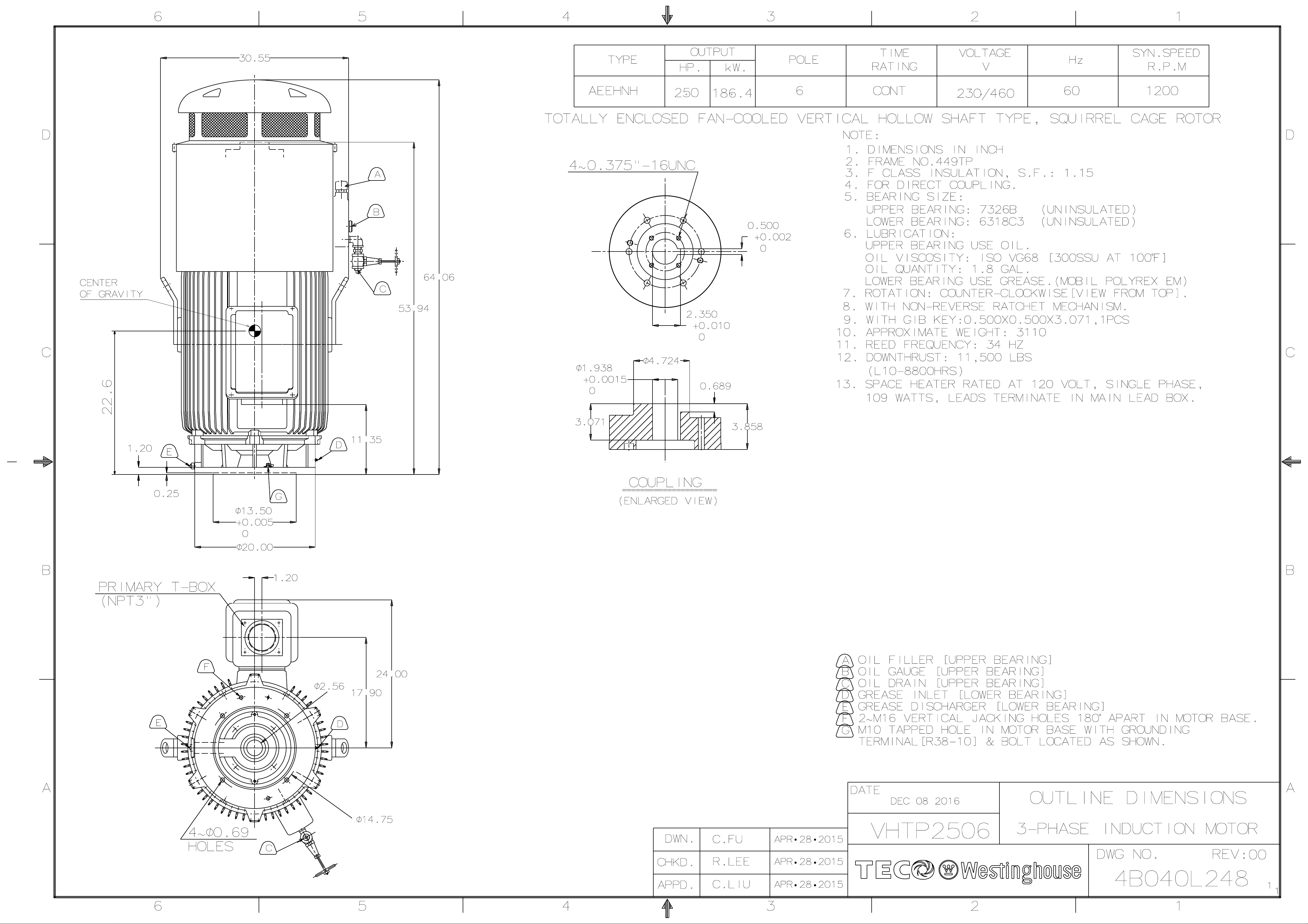
ISSUED MODEL
AEEHNH
1.
2.
3.
APR. 30 2015
REVISED
HIGH THRUST HOLLOWSHAFT PUMP MOTORS
PERFORMANCE DATA
LOW VOLTAGE SQUIRREL CAGE
TEFC, NEMA T-FRAME DESIGN B, CODE G, CLASS F, 40℃ AMBIENT,
CONTINUOUS DUTY, 1.15 S.F. 230/460V 60HZ
TYPICAL PERFORMANCE (460V)
FULL FRAME
LOAD SIZE
HP
EFFICIENCY POWER FACTOR CURRENT
FULL 3/4 1/2 FULL 3/4 1/2 FULL
LOAD %
LOAD LOAD LOAD LOAD LOAD LOAD ROTOR LOAD ROTOR
LOCKED FULL
TORQUE
LOCKED
ROTOR APPROX. REED
BREAK-
DOWN
WR
THRUST
2
DOWN
APPROX.
ROTOR
WEIGHT
WEIGHT FREQ.
RPM (EHV)
1186 442.995.0 94.9 94.5 74.879.8
100
890
1781
125
1186
889
1781.
150 1188
890
1781
200
1188
1783
250
1188
300 1783
NOTE:
NOM. MIN.
444TP
447TP
95.4
445TP
447TP
445TP
447TP
449TP
447TP
449TP
449TP
449TP 328 1977
449TP
95.0
95.0
95.8
95.8 77.2
95.0 94.9 94.5
96.2
96.2
95.8
96.2
THE ABOVE ARE TYPICAL VALUES BASED ON TEST ACCORDING TO ANSI/IEEE STANDARD 112
METHOD B.
BREAKDOWN & LOCKED ROTOR TORQUES ARE SHOWN AS AVERAGE EXPECTED VALUES.
EFFICIENCY, POWER FACTOR, SPEED AND TORQUE ARE THE SAME FOR OTHER VOLTAGES.
CURRENT VALUES VARY INVERSELY WITH VOLTAGE.
4. DECLARED EFFICIENCY HAVN`T TAKEN INTO ACCOUNT OF THRUST LOAD LOSSES
5. TOLERANCE ACCORDING TO NEMA MG1-12& IEC 34-1
6. THRUST LOAD LOSSES ESTIMATED OF ANGULAR CONTACT BALL BEARING AS FOLLOWS:(ACCORDING
TO NEMA STANDARD MG1-12.7)
NOM. NOM.
94.1
94.4 94.0 76.0
93.694.5
95.3 94.9444TP
94.5
94.1 94.9 94.5 64.0
94.9
94.1
95.7 166 1186
95.0
95.7 95.3
95.0
94.1
95.4 96.1
95.0
95.7 76.6
95.4
96.1 95.7
95.0
95.7 95.3
95.4
FRAME SIZE
444TP~445TP
447TP~449TP
7. REDUCING THE THRUST LOAD WILL INCREASE BEARING LIFE AS FOLLOWS:
THRUST(%) 100 82 73 63 56 51
BEARING LIFE(Hrs.) 8800 15000 20000 30000 40000 50000
8. DATA SUBJECT TO CHANGE WITHOUT NOTICE
9. IS SUITABLE FOR 4, 6 POLE UP TO 200HP.
10. 230/460 V UP TO 125HP, 150HP AND ABOVE, APPLY 460/(800) V ONLY
% % % A A lb-ft %FLT %FLT
791
988
1186
1581
590.2791
553.7
738.6988
663.3
885.4
589.9
884.4
736.6292 1977
1105.5
130
143
155 988 10100
161
189 1186
192
235
254 1581
351 2372 883.9
85.6
79.0
76.294.5
95.3
88.0
76.6 71.6 61.6
82.5
95.395.8
83.1
74.3
83.1
64.8 123 100 220 56.8
71.0 61.0
70.6
80.6 8900368.7 100
74.0
71.2 61.2
83.0 73.0
72.2 62.2
77.595.7
61.6
71.6
78.1 68.1
69.3 59.3
68.1
78.196.1 95.7
LOSS HP /100 RPM RPM/1000 LB THRUST
100
220
210
100
220
100
220 140.4
100442.4
210
210
100
100
100
200
100
210
100
210
100 210
100
220
0.0180
0.0194
2
lb-ft
119.6
36.1
66.9
47.9
97.7
189.6220
62.2
123.2
79.3 10100 2840
93.0
LBS
10100 490
12600
12600
8900 1990
11500 2440
12600 2990
10100 2420
11500 2850
11500 3110145.1
10100 3070
LBS
690
400
550
770
470
640
970
53067.5
750
620
840
690
LBS Hz
1950
2390
1960
2060
2570
43
44
43
40
43
41
44
35
44
36
36
34
34
APPD.
CHKD.
DWN.
M.Y.HSU
H.Y.WANG
H.Y.WANG
JUL. 30 2013
JUL. 30 2013
JUL. 30 2013
TECO Electric & Machinery Co., Ltd.
DWG NO.
3A057M068E
REV.00 1/1
DATE:
May
.01.200
9
LOW VOLTAGE
LINE RUN (
2
)△
△△
△
LINE START (
2Y)
HIGH VOLTAGE
LINE RUN (
)△
△△
△
LINE START (
Y)
RUN
( 2
)△
△△
△
T3
T8
12 10 9
7 2 5
6 8 11
1 4 3
12 10 9
7 2 5
6 8 11
1 4 3
12 10 11
6 4 5
7 8 9
1 2 3
9 7 8
6 4 5
12 10 11
1 2 3
12 10 11
4 5 6
7 8 9
1 2 3
12 10 11
6 4 5
7 8 9
1 2 3
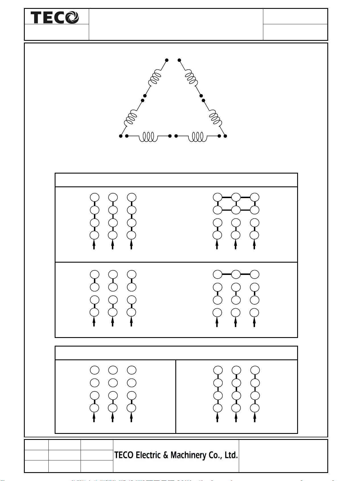
CONNECTION DIAGRAM
4P 2 /△ 2Y/△/Y 12 leads
For Y-△start or PWS on Low Voltage
MODEL
DAC-1705
T5
T1
T4
T7
T10
T2
T11
T6
T9
T12
SCHEMATIC - 2△/2Y/△ /Y CONNECTION
Y-△ start Connection
APPD.
CHKD.
DWN.
START ( )△
M.C.Tsai May,01,’09
C.L.Huang May,01,’09
J.C.Lan May,01,’09
PWS on Low Voltage Connection
△
△△
DWG NO:
DAC-1705
Instructions For
Three Phase Induction Motors
Vertical High Thrust Type
IEC Frame 112 (NEMA Frame 182) and above

Addendum A
1
INDEX
Page
1. INTRODUCTION ..................................................................................................................... 3
1.1 General ............................................................................................................................. 3
1.2 Serial Number of the Machine ........................................................................................ 4
1.3 Mounting Position ........................................................................................................... 4
1.4 Direction of Rotation ....................................................................................................... 4
2. ACCEPTING, INSPECTION, STORAGE, TRANSPORTATION ......................................... 5
2.1 Inspection Upon Receipt ................................................................................................. 5
2.2 Storage ............................................................................................................................. 5
2.3 Transportation ................................................................................................................. 9
3. INSTALLATION ..................................................................................................................... 10
3.1 Site and Environment for Motor Installation ............................................................... 10
3.2 Foundation ..................................................................................................................... 11
3.3 Installation of Shaft Coupling ....................................................................................... 12
3.4 Electrical Connections ................................................................................................... 15
4. OPERATION........................................................................................................................... 17
4.1 Examination Before Start .............................................................................................. 17
4.2 Starting Operation ......................................................................................................... 21
5. MAINTENANCE .................................................................................................................... 25
5.1 Major Points in Regular Inspection and Maintenance ................................................ 25
5.2 Motor Windings ............................................................................................................. 25
5.3 Clean the Interior of the Motor ..................................................................................... 26
5.4 Clean the Exterior of the Motor .................................................................................... 27
5.5 Maintenance of Anti-friction Bearing ........................................................................... 28
5.5.1 Frequency of Relubrication ................................................................................... 28
5.5.2 Kinds of Grease .................................................................................................... 28
5.5.3 Grease Quantity .................................................................................................... 30
5.5.4 Re-Greasing .......................................................................................................... 30
5.5.5 Oil Relubrication (For oil lubrication types only) .................................................. 31
5.5.6 Cleaning and Installation of Bearings .................................................................... 32
5.6 Maintenance of Non-Reverse Ratchet Mechanism ...................................................... 32
5.7 Dismantling and Assembly Procedure .......................................................................... 40
5.8 Records of Operation and Maintenance ....................................................................... 42
6. FAULT FINDING AND RECOGNITION ............................................................................. 37
7. RECYCLE ............................................................................................................................... 39
Appendix 1. Daily Inspection ...................................................................................................... 42
Appendix 2. Monthly Inspection ................................................................................................ 43

2
Appendix 3. Regular Inspection ................................................................................................. 44
Appendix 4. Typical Motor Cross Sectional Drawings
Appendix 4-1. Typical Motor Cross Sectional Drawings
Appendix 4-2. Typical Motor Cross Sectional Drawings
Appendix 5.Typical Motor Cross Sectional Drawings
Appendix 5-2. Typical Motor Cross Sectional Drawings
Appendix 6. Typical Motor Cross Sectional Drawings
::::
SCIM, TEFC .................................... 47
::::
SCIM, TEFC ......................... 48
::::
SCIM, TEFC ......................... 49
::::
ODP ................................................... 50
::::
ODP ....................................... 52
::::
SCIM, TEWC ................................... 53
Appendix 7. Typical Ball Bearing Construction Drawing ......................................................... 54
Appendix 7-1. Typical Ball Bearing Construction Drawing .............................................. 55
Appendix 8. Typical Roller Bearing Construction Drawing...................................................... 56
Appendix 9. Typical Ball Bearing with Insulation Bushing Construction Drawing ................. 57
Appendix 10. Typical Thrust Bearing Assembly Drawing (Vertical Machine) ......................... 58
Appendix 11. Shaft Earth Brush Assembly Drawing (TAC) ..................................................... 59
Appendix 12. Shaft Earth Brush Assembly Drawing (TECO) .................................................. 60
Appendix 13. Bolt Torque (kg-cm) ............................................................................................. 61
Appendix 14. TECO Worldwide Operations ............................................................................. 62
Addendum A
3
1. INTRODUCTION
1.1 General
TECO-Westinghouse high thrust vertical motors covered in this instruction manual are high quality
materials and designed to give long and trouble free service when properly installed, maintained
and operated in strict accordance with the outline drawing, motor nameplates and this instruction
manual. These motors, including both hollow shaft and solid shaft, are generally used to drive
pumps and must not be altered or modified in any unauthorized manner.
High voltage and rotating machinery could cause serious injury or loss of life. Installation,
operation, and maintenance must be performed by qualified and competent personnel only.
Since this instruction manual cannot cover every eventuality of installation, operation and
maintenance, the following points should however be considered and checked.
● Technical data and information on permissible use such as assembly, connection, ambient, area
classification and operating conditions given in the related catalogue, operating instructions,
nameplates and other production documentation.
● General assembly/installation and safety regulations
● Local (job site) and plant-specific specifications and requirements
● Proper use of transport, lifting devices and tools
● Use of personal protective equipment
The following safety indications should be observed when reading these instructions:
Electric Hazard.
Danger.
ATTENTION!!!!
Warning of possible damage to the motor or installation.
This instruction manual is for TECHNICAL USE ONLY, NOT FOR
COMMERCIAL PURPOSE. The warranty is limited to coverage expressed in your
sales contract. Documentation of storage, transportation, installation and examination,
if required, shall be obtained from TECO-Westinghouse service centers before start
and maintenance.
4
1.2 Serial Number of the Machine
Each electric motor is identified with a serial number. Serial number is stamped on a main name
plate which is attached to the frame by rivets.
1.3 Mounting Position
All vertical motors covered in this instruction manual, shall be arranged vertically as shown below
during storage, transportation, handling and installation.
IM3011
Vertical flange mounting (VFM)
Fig. 1 Mounting Arrangement
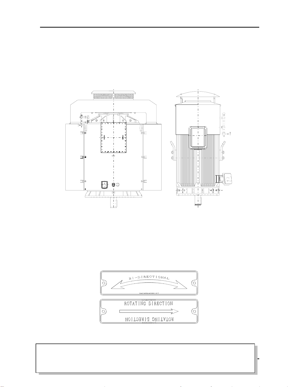
1.4 Direction of Rotation
The arrow on the direction nameplate indicates the direction of the rotation, view from Non Drive
End (or top). The motor must be operated in the direction shown.
Fig. 2 Direction nameplate
ATTENTION!!!!
Operating the motor in the incorrect direction may cause serious damage to both the
motor and driven equipment.
Addendum A
5
2. ACCEPTING, INSPECTION, STORAGE, TRANSPORTATION
2.1 Inspection Upon Receipt
Check the following upon receipt:
● Is there any visible damage to the motor or case? Any damage should be photographed,
documented and reported to the carrier and TECO-Westinghouse immediately.
● Are the nameplate ratings identical with your confirmed order?
● Are dimensions and color in compliance with your specifications?
● Are the nameplate ratings for heater, thermal protector, temperature detector, etc. identical with
your confirmed order?
● Are all accessories and accompanying instruction manuals in good order?
● Does the arrow head indicate the correct direction of rotation?
● If there are any specific requirements, please ensure they are in conformity with your
specification.
● Motor stator housing may be outfitted with condensation drain holes that are either open holes,
drain holes with plugs or drain holes with breather drains. For horizontally mounted motors
position the drain holes at the lowest point possible to allow for the egress of condensation. For
vertical shaft installations the lower end bracket must be outfitted with drains at the lowest point
possible. Prior to installation remove drain plugs if fitted.
2.2 Storage
2.2.1 General
When motors are not in operation, the following precautionary measures must be taken to insure the
motors do not suffer deterioration or damage from moisture, dust and dirt, or careless handling. The
climate, length of time the equipment is to be stored, and the adequacy of the storage facilities will
determine the storage precautions required.
Any deterioration or damage of the motors due to customer's incorrect storage of the motors is not
covered by the warranty. This includes all periods of time when the motor is installed on site but has
not been placed into operation.
The following procedures must be followed and a maintenance log must be kept to keep from
voiding factory warranty. The records are also useful to decide if a motor is suitable or not to be put
into service.
2.2.2 Location
The ideal storage area is a clean, heated, and well-ventilated building.
(a) High and dry, well-ventilated indoor, without exposure to direct sun lights, free from dust,
corrosive gas (such as chlorine, sulfur, dioxide, and nitrous oxides) and fumes, and infestation
by vermin or insects.
(b) The ideal storage temperature range is from 10 ℃to 50℃ (50 to 12℉5℉), and relative
humidity is
≦60%.
(c) Not close to a boiler or freezer.
(d) Precautions should be taken to prevent rodents, snakes, birds or other small animals from
nesting inside the motors. In area where they are prevalent, precautions must be taken to
prevent insects, such as dauber wasps, from gaining access to the interior of motors.

6
(e) Entirely free from vibration. Vibration levels above 3.8 mm/s (0.15 in/sec) velocity could
damage the bearings and cause “false brinelling” of the bearing races.
(f) Motors should be put on pallets to prevent moisture from accumulating underneath.
(g) Motors should be stored in a heated building, outdoor storage is not suitable for motors.
(h) If motors have to be stored outdoors for some reasons, they should be well covered with a
tarpaulin and protected from contamination and moisture. The cover should extend to the
ground however it should not tightly wrap the motor. This will allow the captive air space to
breath, minimizing formation of condensation. Motors should be well shielded from dust, but
under well-ventilated conditions. Outdoor storage should be for a very short period of time
(less than one month) only and the risk of deterioration is the responsibility of the users.
2.2.3 Motor Position
Motors must be stored in vertical position. Where motors are mounted to machinery, the mounting
must be such that drains and breathers are fully operable and are at the lowest point of the motor.
2.2.4 Moisture Prevention
Since moisture can be very detrimental to electrical components, the motor temperature should be
maintained about 5℃ above the dew point temperature by providing either external or internal heat.
If the motor is equipped with space heaters, they should be energized at the voltage shown by the
space heater nameplate attached to the motor. Check weekly that the space heaters are operating.
Incandescent light bulbs can be placed within the motor to provide heat, if the anti-condensation
space heaters are not fitted. However, if used, incandescent bulbs must not be allowed to come in
contact with any parts of the motor because of the concentrated hot spot that could result.
2.2.5 Prevent Corrosion and Frost Damage
When motors are shipped from the factory, external machined surfaces, including the shaft
extension and bearing journals on sleeve bearing motors, are covered with a protective coating. This
coating should be examined periodically to make sure that it has not been accidently removed. If
necessary, re-coat the surfaces with a rust inhibiting material, such as Rust Veto No.342 or an
equivalent. Care should be taken to keep parts such as fitted surface, key, shaft extension, mounting
feet or face, and axial central hole from any collision with foreign matters, and to have rust
preventative in place. It is a good practice to seal any shaft openings with silicone, rubber caulking,
or tape. If any rust is observed, measures should be taken to remove the rust and protect against it.
Grease or anti-corrosion agent should also be generously applied to prevent rusting.
ATTENTION!!!!
Immediately remove any shrink wrap that may have been used during shipping. Never
wrap any motor in plastic for storage. This can turn the motor into a moisture trap
causing severe damage.
For water-cooled motors or motors using bearings with water-cooling coils, please make sure the
water is dried off of the coils to prevent tube corrosion or frost damage.
TECO-Westinghouse reserves the right to void warranties based upon evidence of rust or other
indications of moisture inside the motor that indicate that the motor was improperly stored.
Addendum A
7
2.2.6 Insulation Resistance Test
Even during storage, the insulation resistance should be kept above the specified values.
(a) For measurement of insulation resistance and acceptable standard values, please refer to
measures stated in 4.1.2 "Measurement of insulation resistance".
(b) Insulation resistance test should be performed once every three months.
(c) Resistance measurement of each temperature detector (ex. PT 10
0Ω/℃)
is necessary once every
three months.
2.2.7 Long Period of Idle (storage)
If the motor is not in operation for a long period of time (one week and above) after installation or
has been in operation but stopped for a period of time, the following precautions must be taken.
(a) Protect the motor as stated in 2.2.4 and 2.2.5.
(b) Insulation resistance test should be performed as stated in 2.2.6.
(c) Bearing Protection per 2.2.8.
(d) Operation test should be performed once every three (3) months.
(e) If external vibration is present, the shaft coupling should be opened.
(f) If motors are equipped with drain plugs, they should be removed.
(g) When motors equipped with brushes, the brushes should be lifted in the brush holder, if there is
no protective strip (such as MYLAR) between the brushes and collector rings.
(h) For water-cooled motors or motors using bearings with water-cooled coils, ensure the water is
dried off the coils to prevent tube corrosion or frost damage.
(i) Storage maintenance must be documented for warranty and reference purposes.
2.2.8 Bearing Protection
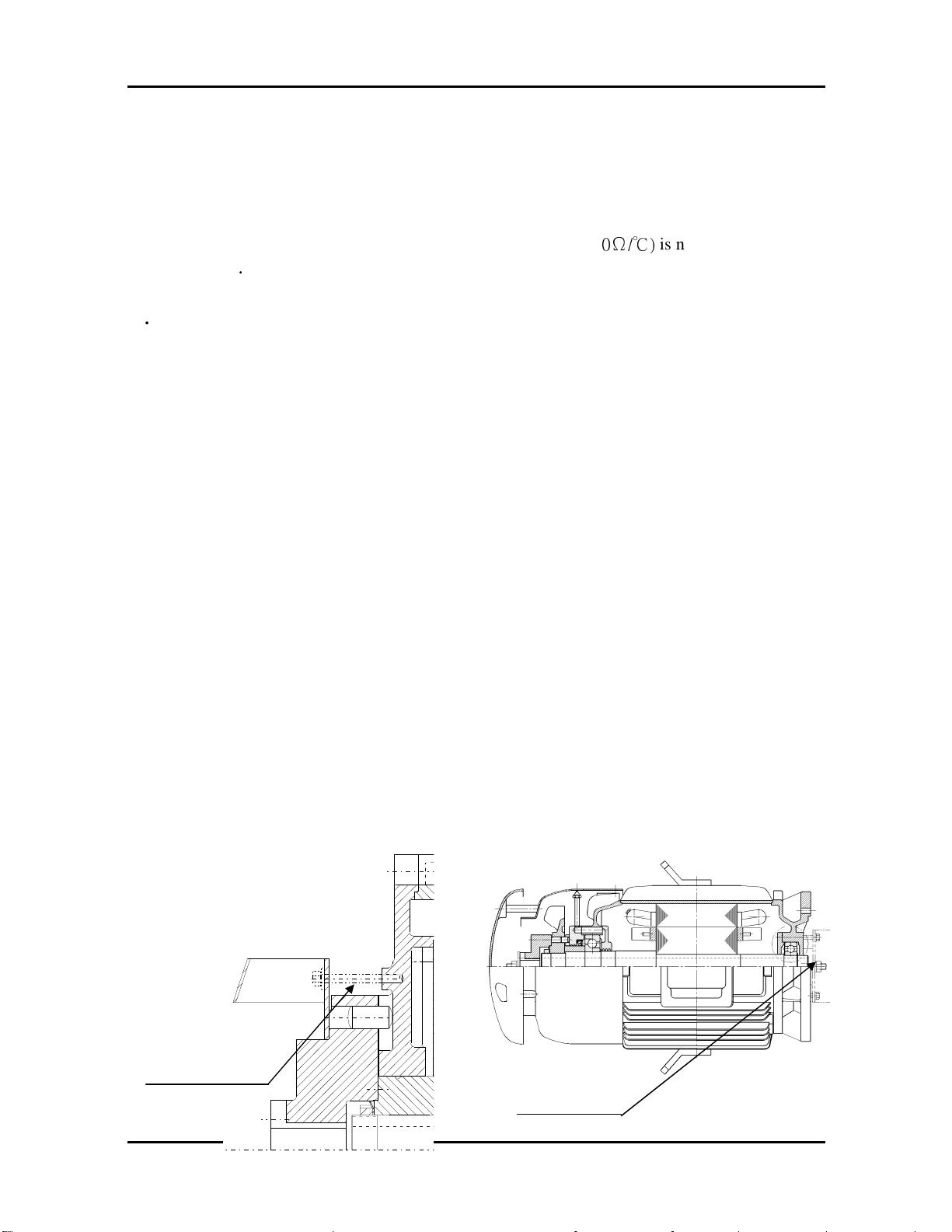
(a) If the motor has been provided with a shaft shipping brace to prevent shaft movement during
transit, it must be removed before operating the motor.
It is very important that this brace be reinstalled exactly as it was originally, before the motor is
moved from storage or any time when the motor is being transported. This prevents axial rotor
movement that might damage the bearings.
Shaft Shipping
Brace
Shaft Shipping
Brace
8
ent
sloshing and possible damage. Refill oil when motor has been moved to the new
Fig. 3-1 Fig.3-2
Shaft Shipping Brace
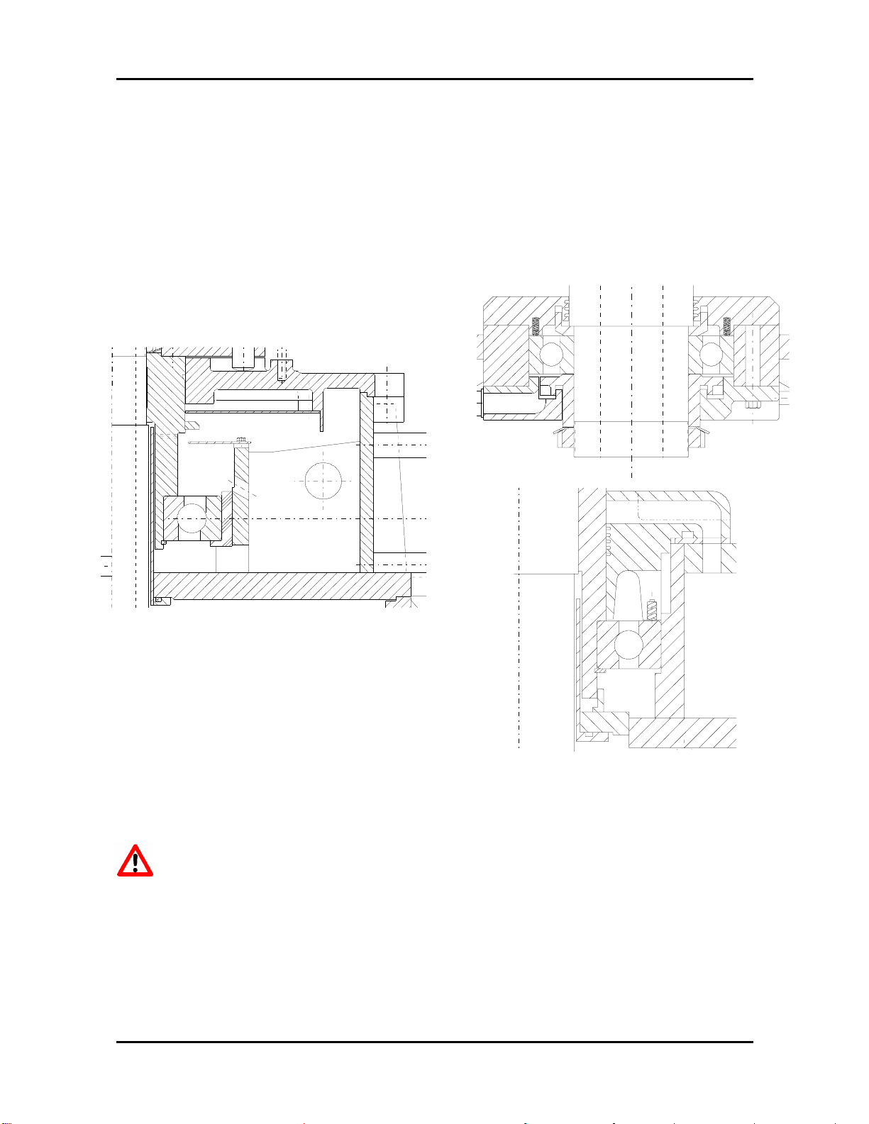
(b) Motors equipped with oil lubricated bearings are shipped from the factory with the bearing oil
reservoirs drained. In storage, the oil reservoirs should be properly filled to the center of the oil
level gauge with a good grade of rust inhibiting oil. To keep the bearing well oiled and prevent
rusting, the motor shaft should be rotated several revolutions every month ensuring the shaft
does not come to rest in its original position. If the motor is not in operation for over six months,
dismount the upper cover of the bearing housing and check the anti-corrosion protection.
Fig. 4 Upper and lower bearing
Motor must not be moved with oil in reservoir. Drain oil before moving to prev
location.

Addendum A
9
(c) Motors with anti-friction bearings are properly lubricated with the correct grade of grease at the
factory and no further greasing is required in storage. If the motor is not in operation for over
three months, add grease to each bearing per lubrication nameplate. The shaft should be rotated
at least 15-20 revolutions every month to maintain proper distribution of the grease within the
bearings.
(d) If the storage is over two years, it is recommended that the bearing assembly be dismantled and
that the bearing parts are inspected before commissioning. Any corrosion has to be removed with
fine emery cloth.
2.2.9 Removal From Storage
After long period of idle or storage, and, prior to energizing the motor, a thorough inspection and
megger test of windings is required. The bearings should be inspected for corrosion, false brinelling
and deformation.
If any of the following conditions exist, then re-conditioning may be required before putting a
motor into service.
(a) Winding resistance is less than recommended.
(b) Evidence of rust or other indications of moisture inside the motor.
(c) Corrosion or false brinelling or deformation occurred in bearings.
(d) Idle or storage longer than the warranty period.
(e) Idle or storage in dirty or damp surroundings.
(f) Storage in unheated area where the temperature and humidity fluctuate.
(g) Idle or storage where it has been subject to vibration, such as from nearby machinery or passing
traffic.
(h) Outdoor storage.
(i) No maintenance records showing that the storage procedures have been followed.
Any reconditioning required, as noted by the inspections after removal from storage, should be
performed prior to putting the motor into service. Such inspection and testing or re-conditioning are
available from local TECO-Westinghouse service/facilities. Reconditioning after idle or storage is
not covered by factory warranty. Any parts that must be replaced due to damage or deterioration
will be at customer’s cost.
2.3 Transportation
ATTENTION!!!!
To keep the rotating parts of motors from moving, thus preventing damage and scratching
during transportation, they should be held securely with a locking device. Ensure all locking
devices are removed before operating the motor. This device must be reinstalled, exactly as it
was originally, before the motor is moved from storage or any time when the motor is being
transported.
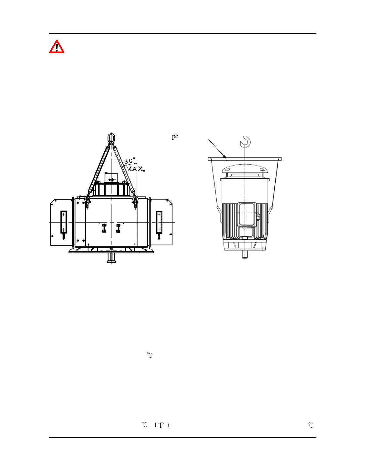
Vertical mount type motors should be transported in a safe stable and vertical position only.
10
Do not use the hoisting hook/eyebolts to lift more than the motor itself. They are
designed to support the motor only.
Make sure the hoisting hook is correctly attached to the eyebolt(s) or lug(s) of the
motor and that the eyebolt(s)/lug(s) are fully threaded in before hoisting. Also note
such parts as fan cover, ventilation box, bracket, slip-ring covers, etc. may have their
own hoisting lugs which can only carry their own weight. Nothing extra should be
attached while hoisting.
Do not twist or cross the steel cables. Make sure the eyebolts have been securely
threaded with the shoulder flush and the sling angle is correct.
Suspension Rod
Fig. 5
3. INSTALLATION
3.1 Site and Environment for Motor Installation
3.1.1 General
Standard environment and site conditions for the installation of motors are usually set as follows:
(a) Ambient temperature: -20 ~ +40 ℃
(b) Humidity: Relative humidity shall be below 95%RH for totally-enclosed types, and below
80%RH for semi-enclosed types.
(c) Elevation: Below 1000 meters.
(d) Harmful gases, liquids, dusts and high moisture levels should be absent.
(e) Foundations should be strong and free of vibration.
For water-cooled motors or motors using bearings with water-cooling coils, the ambient
temperature must not drop below 5 (℃41℉) to prevent frost damage. If lifting a motor under -20
℃
Addendum A
11
is required, or there are any special environmental conditions, please inform us at time of order.
3.1.2 Ventilation and Space
(a) Installation area should be well-ventilated.
(b) The installation space should be large enough to facilitate heat dissipation and maintenance.
3.2 Foundation
Motor manufacturer is not responsible for the foundation design. Motor weight, thrust load, twisting
moments, seismic forces and other external applied loads must be considered in foundation design
by others.
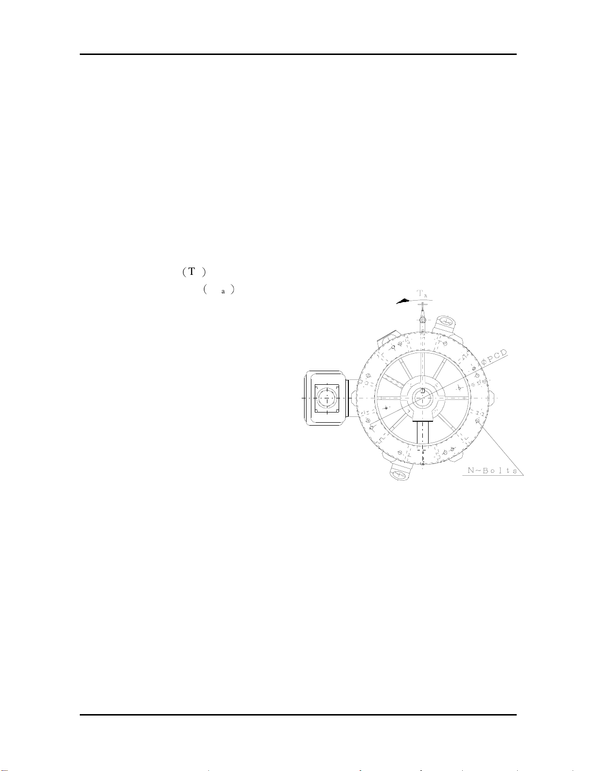
3.2.1 Reactions of Vertical Motor
For a vertical motor with N pcs hold down bolts, the reactions necessary for foundation design are
as follows – kgs per bolt at centerline of hold down bolt holes:
(a) Rated motor torque(T
(b) Maximum motor torque(T
Reactions = T
/ bolt number/ PCD/2
max
)
, reactions = TR / bolt number/( PCD/2 )
R
)
,
max
Fig. 6
3.2.2 The foundation of vertical induction motor (Also the foundation of pump)
(a) Foundation of motor/pump must be rigid and secure to provide adequate support. There must be
no vibration, twisting, misalignment etc. due to inadequate foundations.
(b) A massive concrete foundation is preferred in order to minimize vibration. Rigidity and stability
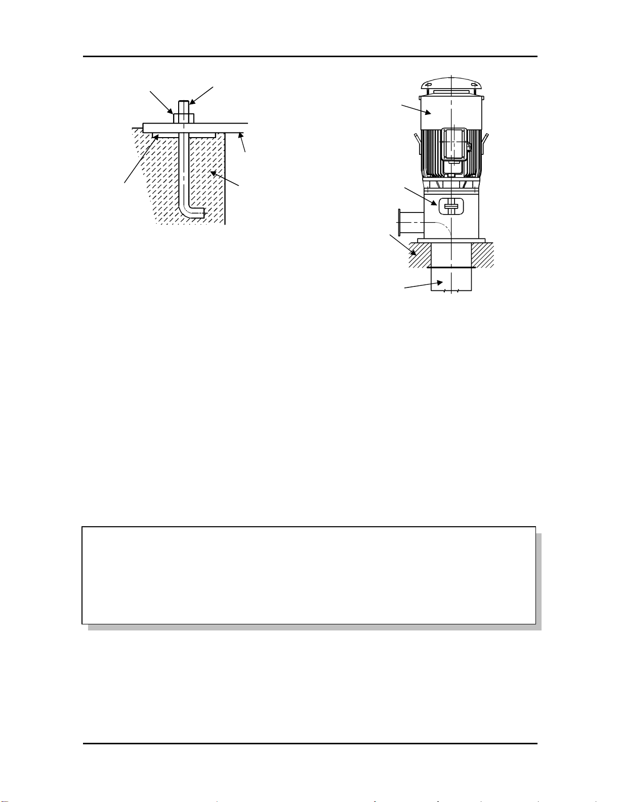
are enhanced by prop plate and foundation bolt. As shown in Fig.7 and Fig.8.
12
Foundation bolt
(SS41)
Pump
Prop plate
Hex nut
Motor
Base plate
Motor support
Concrete
Base foundation
Fig. 7
3.2.3 Installation of vertical motor
(a) All mounting surfaces must be clean and level.
(b) Foundation must be leveled at least at 4 points and guaranteed to be below 0.04mm flat and
level.
(c) Make sure the mortar and concrete are completely dry, and the precision of the level is
acceptable, then set the motor on the mounting foundation.
(d) Accurately install shaft couplings.
Fig. 8
3.3 Installation of Shaft Coupling
3.3.1 General
ATTENTION!!!!
Motors must always be accurately aligned, and this applies especially where they are
directly coupled.
Incorrect alignment can lead to bearing failure, vibration and even shaft fracture. As soon
as bearing failure or vibration is detected, the alignment should be checked.
3.3.2 Mounting procedure
Field installation of a coupling to the motor shaft should follow the procedures recommended by the
coupling manufacturer. The motor shaft extension must not be subjected to either extreme heat or
cold during coupling installation.
3.3.3 Alignment
The motor shaft and the driven shaft should be aligned within the following tolerances in both
angular and parallel alignment:
Addendum A
TIR Range of rotating speed
Solid coupling
Flexible coupling
C 2500rpm and above
0.03 0.03
“A” TIR
indicator
Indicator
base
“C” TIR
indicator
base
Below 2500rpm 0.04 0.05
A 2500rpm and above 0.03 0.03
Below 2500rpm 0.03 0.04
Unit:mm
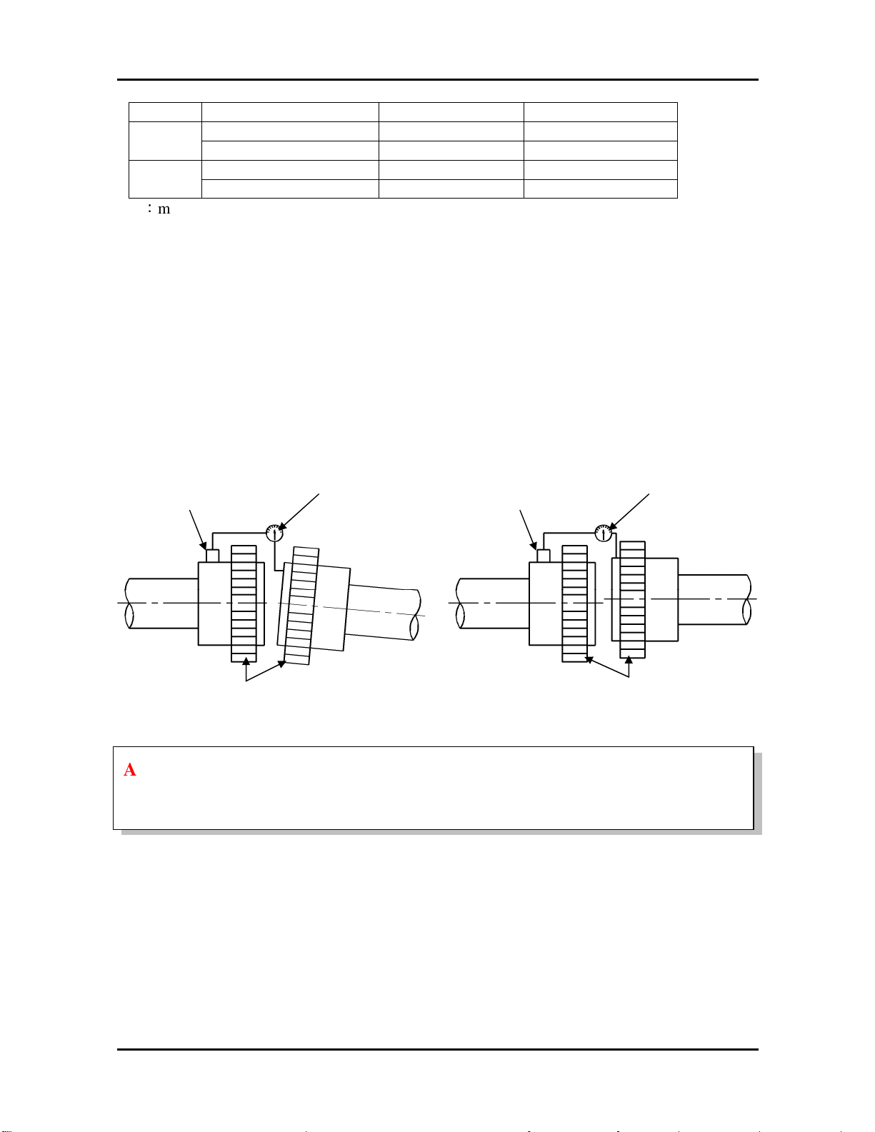
Angular misalignment is the amount by which the centerlines of driver and driven shaft are
skewed. It can be measured using a dial indicator set up as shown in Fig.9. The couplings are
rotated together through 360 degrees so that the indicator does not measure run out of the coupling
hub face. The shafts should be forced against either the in or out extreme of their end float while
being rotated.
Parallel misalignment is the amount by which the centerlines of the driver and driven shafts are
out of parallel. It can be measured using a dial indicator set up as shown in Fig.10. Again, the
couplings are rotated together through 360 degrees so that the indicator does not measure runout of
the coupling hub outside diameter.
TIR = Total indicator reading (by dial indicator)
Indicator
13
Coupling Hubs
Fig. 9 Fig. 10
Coupling Hubs
ATTENTION!!!!
Measurements should be made only after shimming and with hold-down bolts properly
tightened.
3.3.4 Dowel for Motor
After the motor has been properly aligned with the driven equipment and the hold-down bolts have
been installed and tightened, for motors with fabricated frame, at least two dowel pins should be
installed in two diagonally opposite motor feet.
3.3.5 Installation of Shaft Coupling (Vertical Hollow Shaft Motor Only)
Bolted coupling as Fig.11
(a) Bearings are provided to absorb some upward shaft thrust when the coupling is fitted.
(b) The coupling is fastened with bolts.
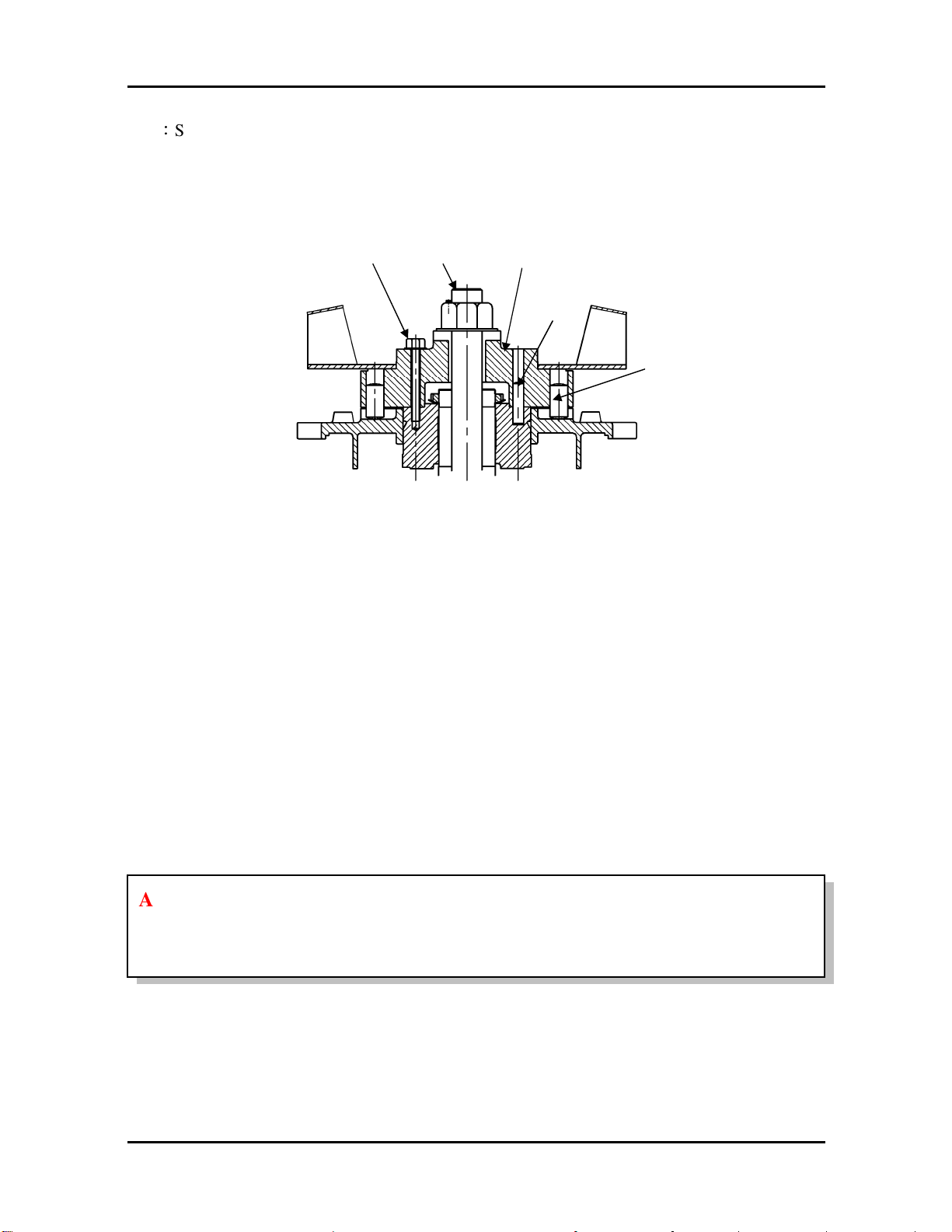
14
bolt
Pump
Driv
e
(c) This coupling type is not auto-release type.
Note:Standard high thrust motors can absorb momentary up thrust load up to 30% of the standard
down thrust load. If the up thrust is long duration (over 10 seconds) and/or exceeds 30% of
the standard high thrust rating, special design arrangements are required and a standard
motor is not suitable.
Up thrust
shaft
coupling
Drive
pin
Ratchet pin
Fig. 11
3.3.6 Non-Reverse Ratchet/Coupling, as Fig. 11 (If fitted)
The non-reverse coupling is also a bolted type and,
(a) It prevents the pump and motor from rotating in the reverse direction.
(b) It also prevents damage from over speeding and damage to pump shaft and bearings.
(c) The ratchet pins or balls are lifted by the ratchet teeth and are held clear by centrifugal force and
friction as the motor comes up to speed.
(d) When power is removed, speed decreases, and the pins or balls fall. At the instant of reversal, a
pin or ball will catch in a ratchet tooth and prevent backward rotation.
(e) When installing the non-reverse coupling, do not use lubricant. Lubrication will interfere with
proper operation. The top half of the coupling should seat solidly on the lower half and the pins
or balls should touch the bottom of the pockets between the teeth in the plate.
(f) As with the bolted coupling, the up thrust capabilities are 30% of the standard high thrust rating
for down thrust.
ATTENTION!!!!
Do not apply non-reverse ratchets on applications in which the pump reversal time from
shutdown (the instant the stop button is pressed) to zero speed is less than one second.
3.3.7 Manual Rotation of Large Vertical Rotor with Sleeve Bearing During Alignment
(a) If there is a thread in the non-drive end shaft center, the breakaway torque can be overcome by
the use of torque wrench provided there is no ratchet. Remove the top cover, insert a bolt in the
threaded shaft center and use a torque wrench to apply the rotating force. The breakaway torque
value will determine the size of torque wrench required.
Addendum A
Coupling
Coupling
shaft
shaft
Torque [kg-mm] = Rotor Wt [kg] * Thrust Pad Center Radius [mm] * 0.4
0.4 = coefficient of friction for dry lubrication
(b) An alternate is to use a long bar bolted to the coupling to apply the torque.
(c) If the rotor can be lifted either from above using a crane attached to the top of the rotor or from
below using a jack, then the rotor weight is reduced and the torque needed to breakaway is much
less. This does not always work, as sometimes the pads adhere to the thrust collar face due to
cohesion.
There is no danger of Babbitt damage due to breakaway because it only takes a small revolution of
the rotor to lubricate all shoe surfaces.
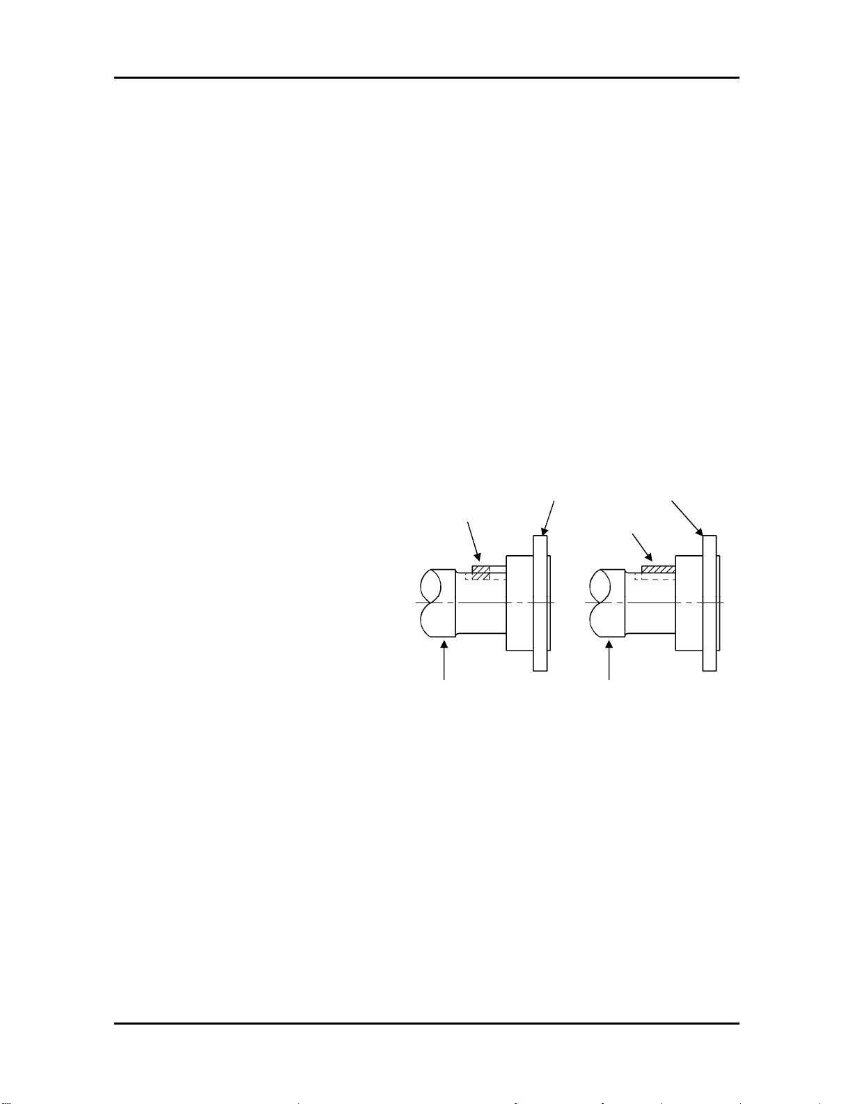
3.3.8 Removal of Redundant Shaft Key
When the length of coupling hub is different from the length of shaft key, the motor may have a
high vibration level due to this unbalance condition. The removal of redundant shaft key is
necessary, shown as Fig.12.
15
Method (1):
After installing the coupling, use a
grinding wheel to remove the redundant
key (hatch area).
Method (2):
Before installing the coupling, calculate
the different length between coupling hub
and shaft key, then cut the half of this
different value (hatch area) to achieve
approximate-balance condition.
Redundant
key
Drive-end
Method (2) Method (1)
Redundant
key
Drive-end
Fig. 12
3.4 Electrical Connections
All interconnecting wiring for controls and grounding should be in strict accordance with local
requirements such as the USA National Electrical Code and UK IEE wiring regulations.
Wiring of motor and control, overload protection and grounding should follow the instructions of
connection diagrams where provided.
16
The bolted joints between the motor lead and the power cables must be made and
ing
3.4.1 Power
The rated conditions of operation for the motor are as shown on the nameplate. Within the limits,
given below, of voltage and frequency variation from the nameplate values, the motor will continue
to operate but with performance characteristics that may differ from those at the rated conditions:
+/- 10% of rated voltage
+/- 5% of rated frequency
+/- 10% combined voltage and frequency variation so long as frequency variation is no
more than +/- 5% of rated
ATTENTION!!!!
Operating the motor at voltages and frequencies outside of the above limits can result in
both unsatisfactory motor performance and damage to or failure of the motor.
3.4.2 Main Lead Box
The main lead box furnished with the motor has been sized to provide adequate space for the
make-up of the connections between the motor lead cables and the incoming power cables.
insulated in accordance with the best industry practices.
3.4.3 Grounding
Both fabricated steel motors and fan cooled cast frame motors are provided with grounding pads or
bolts.
The motor must be grounded by a proper connection to the electrical ground
system.
3.4.4 Rotation Direction
The rotation direction of the motor will be as shown by a nameplate on the motor, specification
table or the outline drawing. The required phase rotation of the incoming power for this motor
rotation may also be stated. If either is unknown, the correct sequence can be determined by the
following method.
Make sure the motor is uncoupled and the non-reverse ratchet (if installed) has been disabled
according to 5.6.3., start the motor and observe the direction of rotation. Allow the motor to achieve
full speed before disconnecting it from the power source. Refer to the operation section of this
manual for information concerning initial start-up. If resulting rotation is incorrect, it can be
reversed by interchanging any two (2) incoming cables.
3.4.5 Auxiliary Devices
Auxiliary devices such as resistance temperature detectors, thermocouples, thermoguards, etc., will
generally terminate on terminal blocks located in the auxiliary terminal box on the motor. Other
devices may terminate in their own enclosures elsewhere on the motor. Such information can be
obtained by referring to the outline drawing. Information regarding terminal designation and the
Addendum A
During and immediately after measuring, the terminals must not be touched as they
nected and there are no moving
connection of auxiliary devices can be obtained from auxiliary drawings or attached nameplates.
If the motor is provided with internal space heaters, the incoming voltage supplied to them must be
exactly as shown by either a nameplate on the motor or the outline drawing for proper heater
operation.
ATTENTION!!!!
Caution must be exercised anytime contact is made with the incoming space heater circuit
as space heater voltage is often automatically applied when the motor is shutdown.
4. OPERATION
4.1 Examination Before Start
4.1.1 Wiring Check
For proper motor installation, ensure the wiring diagram is followed and the points below are
adhered to:
(a) Make sure all wiring is correct.
(b) Ensure the sizes of cable wires are appropriate and all connections are well made for the
currents they will carry.
(c) Ensure all connections are properly insulated for the voltage and temperature they will
experience.
(d) Ensure the capacity of fuse, switches, magnetic switches and thermo relays etc. are appropriate
and the contactors are in good condition.
(e) Make sure that frame and terminal box are grounded.
(f) Make sure the starting method for the motor in question is followed correctly.
(g) Make sure switches and starters are set at the correct positions.
(h) Motor heaters must be switched off when the motor is running.
4.1.2 Measurement of Insulation Resistance
17
may carry dangerous residual voltages. Furthermore, if power cables are connected
make sure that the power supplies are clearly discon
parts.
(a) For rated voltage below 1000V, measure with a 500VDC megger.
For rated voltage above 1000V, measure with a 1000VDC megger.
(b) In accordance with IEEE 43-2000, there are three recommendation minimum insulation
resistance values. These values corrected to 40℃ are:
(1) kV+1 in Megohms for most windings made before 1970, all field windings and windings not
otherwise described.
(2) 100 Megohms for most DC armatures and AC windings built after about 1970 with form

18
wound coils.
(3) 5 Megohms for machines with random wound stator coils and for form wound coils rated
below 1kV.
ATTENTION!!!!
After measurement the winding must be grounded or shunted to discharge residual
voltages.
(c) On a new winding, where the contaminant causing low insulation resistance is generally
moisture, drying the winding through the proper application of heat will normally increase the
insulation resistance to an acceptable level. The following are several accepted methods for
applying heat to a winding:
(1) If the motor is equipped with space heaters, they can be energized to heat the winding.
(2) Direct current (as from a welding equipment) can be passed through the winding. The total
current should not exceed approximately 20% of rated full load current. If the motor has
only three leads, two must be connected together to form one circuit through the winding. In
this case, one phase will carry the full applied current and each of the others, one-half each.
If the motor has six leads (3 mains and 3 neutrals), the three phases should be connected into
one series circuit.
Ensure there is adequate guarding so live parts cannot be touched.
(3) Heated air can be either blown directly into the motor or into a temporary enclosure
surrounding the motor. The source of heated air should preferably be electrical as opposed to
fueled (such as kerosene) where a malfunction of the fuel burner could result in carbon
entering the motor.
ATTENTION!!!!
Caution must be exercised, when heating the motor with any source of heat other than self
contained space heaters, to raise the winding temperature at a gradual rate to allow any
entrapped moisture to vaporize and escape without rupturing the insulation. The entire
heating cycle should extend over 15-20 hours.
Insulation resistance measurements can be made while the winding is being heated. However,
they must be corrected to 40℃ for evaluation since the actual insulation resistance will
decrease with increasing temperature. As an approximation for a new winding, the insulation
resistance will be approximately halved for each 10°C increase in insulation temperature
above the dew point temperature.
(d) Should the resistance fail to attain the specified value even after drying, careful examination
should be undertaken to eliminate all other possible causes, if any.
4.1.3 Power Source

Addendum A
19
(a) Ensure the capacity of the power source is sufficient.
(b) Ensure the supply voltage and frequency ratings are identical to those on the nameplate.
(c) Voltage variation should be confined to ±10% of the rated value and the phase to phase voltages
should be balanced.
4.1.4 Bearing Lubrication
(a) For oil lubricated bearing motors, the oil reservoir must be filled with oil to the correct level. On
self-lubricated bearings, the standstill oil level will be at the center of the oil gauge. The proper
oil is a rust and oxidation inhibiting, turbine grade oil. Refer to the lubrication nameplate for the
recommended viscosity.
(b) Motors which are supplied with provision for flood lubrication have an inlet regulator to meter
the oil flow to the bearing. Refer to the outline drawing for this accessory. If the supply oil
quantity does not match that stated on the outline, the oil regulator must be adjusted to the
specified flow rate. In line with operation conditions (degree of contamination of the oil) filters
must be cleaned according to the instructions of the manufacturer. The recommendation mesh
size of the filters is 15~20μm.
Oil inlet temperature:
Normal
Alarm
Trip
20℃ (70℉) ~ 49℃ (120℉)
60℃ (140℉)
65℃ (150℉)
(c) If the motor is in storage for over three (3) months, refilling of some new oil should be
undertaken before operation to prevent bearing damage due to dry friction. The oil level should
be kept at the center of the oil gauge. If necessary, drain some oil after refilling.
(d) Grease lubricant type
(1) The bearings have been well greased at factory before delivery. However, regreasing is
required if a significant period has elapsed between manufacture and use or in storage. Fill
new grease until it overflows and the old grease is entirely replaced.
(2) Unless otherwise specified and shown on nameplate, ExxonMobil Polyrex EM is the
standard applied to TECO-Westinghouse motors.
(3) If roller bearing is used, add a small amount of grease if abnormal sound occurs in the
bearings. If this sound, disappears temporarily after regreasing, it is a normal condition
and can operate as it is, as long as the temperature rise of the bearing is normal.
4.1.5 Cooling Water for the Cooler on Water-Cooled Motors
Make sure the quality, volume and inlet temperature of cooling water for the motors are normal
before the machine is in operation.
Water:General tower water or industrial water, the suspended solid shall be below 20μm/l
Volume:Please see outline drawing
Inlet temperature:Normal below 30℃ (86℉);above 5℃ (41℉)
Alarm
Trip
35℃ (95℉)
40℃ (104℉)
Special temperature settings will be noted in outline drawings.

20
The keys fitted to the shaft extensions are held by plastic tape only to prevent them
falling out during transportation or handling. The shaft key shall be removed to
being
4.1.6 For Motors Equipped with Independent Force-Ventilating Blower Unit
(a) Ensure the voltage and frequency of the power source are identical to the ratings shown on
blower motor name plate.
(b) Ensure the wiring to blower motor is according to the connection diagram.
(c) Test run the blower motor to ensure the phase currents are within the tolerance limits.
(d) Ensure the cooling air flow direction is correct. Refer to motor outline for cooling air flow
direction.
(e) Blower motor should be started prior to operating the main motor.
(f) Do not switch off the blower motor immediately after the main motor is shut off. It must be left
running for 15 minutes after the main motor is shut down.
(g) For small blower motor, double shield and pre-lubricated ball bearings are used and
re-lubrication is not necessary.
4.1.7 Remove All Locks
ATTENTION!!!!
Make sure all locks which fasten the movable parts of the motor during transportation
are dismantled and removed so the shaft can rotate freely.
4.1.8 Clean Before Starting
ATTENTION!!!!
Ensure there are no foreign objects or tools inside the motor before starting.
4.1.9 Transmission System Check
Make sure the transmission system, including belts, screws, bolts, nuts and set pins are in good
condition.
from
prevent it from flying out when the motor is operated prior to the couplings
fitted to the shaft extension.
4.1.10 Test Run
Make sure the items above are examined. Test the motor running with or without load. Record and
check according to the statement of 5.8 "Records of operation and maintenance" at 15 minute
intervals during the first three hours of operation. Then regular examinations should take place at
longer intervals. If everything goes well, the motor can be classified as "in good order".
ATTENTION!!!!
To avoid the abnormal bearing temperature and vibration level increases, it is not
recommended to run a vertical high thrust motor continuously without load.

Addendum A
21
4.2 Starting Operation
4.2.1 Starting Load
Initially run the motor unloaded prior to coupling to the driven machine. Unless otherwise specified,
a motor usually starts with light load which is then gradually increased proportional to the square of
speed and at last reaches 100% load at full load speed.
4.2.2 Starting
Too frequent starts can harm the motors. The following restrictions should be observed:
(a) Motor can be restarted should the initial start fail. Two starts are generally permissible when the
motor is cold.
(b) Motor can be started only once when it is at normal running temperature.
(c) Should additional starts be necessary beyond the conditions stated above, the following
restrictions should be noted:
(1) Let the motor cool down for 60 minutes before restarting, fully loaded.
(2) Let the motor cool down for 30 minutes before restarting, unloaded.
(3) Two inching starts can be regarded as one normal start.
ATTENTION!!!!
If the motor rotor fails to start turning within one or two seconds, shut off the power
supply immediately.
Investigate thoroughly and take corrective action before attempting a restart.
Possible reasons for not starting are:
(1) Voltage drop at the motor terminals is more than allowed (look to confirmed data sheet).
(2) The counter torque is too large to accelerate the rotor.
(3) The driven machine is stuck, jammed or blocked.
(4) The electrical connections have not been made according to drawings and standards.
(5) One phase is missing or single phase power has been applied.
(6) Any combination of the above.
4.2.3 Rotating Direction
(a) Most TECO-Westinghouse motors can be operated in bi-directional rotation. However, when
some special types, such as high speed 2P, certain large capacity motors, those with a
non-reverse ratchet etc. should rotate in one direction, please ensure the rotation is in conformity
with the directional arrow-mark shown on the attached nameplate.
(b) To reverse a bi-directional motor, cut the power and wait until the motor stops. Then interchange
any two of the three phases.

22
4.2.4 Power Source, Voltage, Current
(a) Ensure the voltage and frequency of the power source are identical to the ratings shown on the
nameplate.
(b) Voltage variation should be confined to ±10% of the rating and the three phase voltages should
be in full balance.
(c) Ensure the motor phase currents in no-load condition could be variably, within ±5% of the
average values.
4.2.5 Power Source, Frequency
The variation of the frequency should be confined to ±5% of the rating. The aggregate variation of
voltage and frequency should be confined to ±10% of the absolute value of the ratings.
4.2.6 Starting Time and Unusual Noises
ATTENTION!!!!
Starting time is longer for the motors with large inertia. However, if starting time is longer
than usual or if there is difficulty in starting, or there is abnormal noise, do not run the
motor and refer to TECO-Westinghouse.
4.2.7 Bearing Temperature Rise
Following the initial start-up, the bearing temperatures should be closely monitored. The rise rate of
bearing temperature is more indicative of impending trouble than is the actual temperature.
ATTENTION!!!!
If the rise rate of the temperature is excessive; the motor exhibits excessive vibration
and/or unusual noise, shut down the motor immediately. Before starting up the motor
again a thorough investigation must be made to determine the cause.
If the bearing temperature rise and motor operation appear to be normal, operation should continue
until the bearing temperature is stabilized.
Recommended limits on bearing temperature are as follows:
Alarm Trip
95°C (203°F) 100° C (212°F)
When special synthetic lubrication oil was used under high ambient temperature case, such as
50~55℃, above temperature setting could by adjusted to alarm 110℃ & trip 115℃ after checking
with factory engineers.

Addendum A
1200
20
0.15 (3.8)
900 15 0.12 (3.0)
720 12 0.09 (2.
3)
ATTENTION!!!! (For sleeve bearing)
(1) Flood lubrication sleeve bearings without external lubrication supply, the bearing
temperature must not be allowed to exceed 85
(2) Self-lube bearing or self-lube with water cooled, the rate of temperature rise should be
from 11K to 14K for the first ten (10) minutes after starting up and approximately 22K
at thirty (30) minutes. The rate of bearing temperature rise is a function of the natural
ventilation and operating conditions.
(3) When the rate of bearing temperature rise is less than
bearing temperature is considered to steady conditions.
(4) If the total bearing temperature exceeds 95
immediately and a thorough investigation must be made to determine the cause.
℃℃℃℃
in total.
±±±±
1K per (30) minutes, the
℃℃℃℃
, the motor should be shut down
ATTENTION!!!!
If the rise rate of the temperature is excessive; the motor exhibits excessive vibration and/or
unusual noise, shut down the motor immediately. Before starting up the motor again, a
thorough investigation must be made to determine the cause.
23
4.2.8 Noise and Vibration
ATTENTION!!!!
Any abnormal noise or vibration should be immediately investigated and corrected.
Increased vibration can be indicative of a change in balance due to mechanical failure of a
rotor part, a stator winding problem or a change in motor alignment.
(a) NEMA MG1, vibration limits at no load
Unfiltered Vibration Limits
Speed, rpm Rotational
Frequency, Hz
3600 60 0.15 (3.8)
1800 30 0.15 (3.8)
600 10 0.08 (2.0)
Velocity, in./s peak
(mm/s)
(b) ISO 10816, overall vibration severity chart for customer’s reference

24
4.2.9 Recommended Winding Temperature Settings
An electric motor normally has built in “over temperature protection devices” such as thermistors
and RTD’s. They are set to trip at levels dependent upon the Class of Insulation of the motor
windings. Motors designated Class F insulation have an allowable total temperature of 155°C in
total. For those motors, the recommended alarm and trip settings are as below:
Alarm Trip
140°C (284°F) 155°C (311°F)
4.2.10 Additional Points to Note
(a) The motor characteristic data includes values for the acceleration and safe stall times, when
specified by the customer. If the motor fails to reach full speed, shut off the power immediately.
Investigate thoroughly and take corrective action before attempting to restart.
(b) Each start of an induction motor subjects the motor to full inrush current with resulting heating
of the stator and rotor windings. Each acceleration and repeated start can produce more heat
than that produced and dissipated by the motor under full load.
The starting duty for which the motor is designed is shown by a nameplate mounted on the
motor and must not be exceeded, if long motor life is expected. Abnormally terminal voltage
drop and/or excessive load torque during motor start-up can cause extended acceleration time
during which rotor speed is reduced and ventilation is minimized. This can cause rotor
destroying or can lead to extreme shortening of the rotor life.
(c) The temperature rating of the motor is shown on the main nameplate as a temperature rise above
an ambient temperature. If there is a service factor, it is also shown.
If the motor does not have stator winding temperature detectors and abnormal winding
temperatures (as might be indicated by high discharge air temperature, odor, etc.) are suspected,
the motor should be shut down immediately and an investigation made before further operation
is attempted.

Addendum A
Some testing, such as insulation resistance, usually requires the motor to be stopped
25
5. MAINTENANCE
5.1 Major Points in Regular Inspection and Maintenance
Maintenance and repairs must only be carried out by properly trained personnel.
and isolated from power supply(ies).
Routine inspection and maintenance are usually performed visually, audibly, by odor, and by means
of simple meters.
High temperatures may arise under normal operating conditions on the motor
surfaces, so touching should be prevented or avoided.
Keep away from moving and live parts.
Unless deemed necessary, do not remove guards while assessing the motor.
Timely replacement of worn parts can assure longevity and prevent breakdown.
Routine and regular inspection and maintenance are important in preventing breakdown and
lengthening service life.
Owing to the varied time and circumstances in which motors are used, it is difficult to set the items
and periods for regular inspection and maintenance. However, as a guide, it is recommended to be
performed periodically according to factory maintenance program. Generally, the inspection scope
is determined by the following factors:
(a) Ambient temperature and ambient conditions (dust, humidity, other contamination).
(b) Starting and stop frequency.
(c) Troublesome parts usually affect motor operation.
(d) Easily worn parts (ground brushes).
(e) The importance of motors in the operational system should be duly recognized. Therefore,
regular inspection and maintenance will prolong the life of the motor, especially when it is
operating in severe conditions.
5.2 Motor Windings
(a) Measurement of insulation resistance and standards to determine quality of insulation resistance,
please refer to measures stated in 4.1.2 "Measurement of insulation resistance".
(b) Inspection of coil-ends:
(1) Grease and dust accumulated on coils may cause insulation deterioration and poor cooling
effect.
(2) Moisture must not accumulate. Keep coils warm when motor is not in use (use space heater,
if it’s installed).
(3) Discoloring. This is mainly caused by overheating.
(c) Ensure no untoward change of wedges from original position occurs.
(d) Ensure the binding at the coil end is in its normal position.

26
Adequate ventilation must always be provided in any area where solvents are being
used to avoid the danger of fire, explosion or health hazards. In confined areas (such
an air line respirator, a hose mask or a
contained breathing apparatus. Operators should wear goggles, aprons and
suitable gloves. Solvents and their vapors should never be exposed to open flames or
5.3 Clean the Interior of the Motor
(a) After a motor has been in operation for some time, accumulation of dust, carbon powder and
grease etc., on the inside is unavoidable, and may cause damage. Regular cleaning and
examination is necessary to assure top performance.
(b) Points to note during cleaning:
(1) If using compressed air or a blower:
a) Compressed air should be free of moisture. Be sure, that the dust and other materials can
come out of motor housing, iron core and windings.
b) Maintain air pressure below 4 kg/cm2, since high pressure can cause damage to coils.
(2) Vacuum
Vacuum cleaning can be used before and after other methods of cleaning, to remove loose
dirt and debris. It is a very effective way to remove loose surface contamination from the
winding without scattering. Vacuum cleaning tools should be non-metallic to avoid any
damage to the winding insulation.
(3) Wiping
Surface contamination on the winding can be removed by wiping using a soft, lint-free
wiping material. If the contamination is oily, the wiping material can be moistened (not
dripping wet) with a safety type petroleum solvent.
In hazardous locations, a solvent such as inhibited methyl chloroform may be used, but must
be used sparingly and immediately removed. While this solvent is non-flammable under
ordinary conditions, it is toxic and proper health and safety precautions should be followed
while using it.
ATTENTION!!!!
Solvents of any type should never be used on windings provided with abrasion
protection. Abrasion protection is a gray, rubber-like coating applied to the winding
end-turns.
as pits) each operator should be provided with
self-
sparks and should always be stored in approved safety containers.

Addendum A
because any dislodged dirt or debris can be drawn directly into the motor.
(4) Keep core ducts completely clean. The difference in temperature rise could be around 10℃
before and after cleaning.
(A) Riveted
Core ducts
(B) Welded with riveting films
(C) Welded with core bars
Fig. 14
27
5.4 Clean the Exterior of the Motor
(a) On open ventilated motors, screens and louvers over the inlet air openings should not be allowed
to accumulate any build-up of dirt, lint, etc. that could restrict free air movement.
ATTENTION!!!!
Screens and louvers should never be cleaned or disturbed while the motor is in operation
(b) If the motor is equipped with air filters, they should be replaced (disposable type) or cleaned and
reconditioned (permanent type) at a frequency that is dictated by conditions. It is better to
replace or recondition filters too often than not often enough. The Permanent type air filters can
be cleaned with fresh water, make sure to let them dry before reinstalling.
Disposable type filter fitted into two filter supports. Permanent type filter.
Fig. 15 Fig. 16
(c) Totally enclosed air-to-air cooled and totally enclosed fan cooled motors require special cleaning
considerations. The external fan must be cleaned thoroughly since any dirt build-up not removed
can lead to unbalance and vibration. All of the tubes of the air-to-air heat exchanger should be
cleaned using a suitable tube brush having synthetic fiber bristles (not wire of any type).
(d) It is important to keep the external surfaces of any motor clean and free from buildup of dirt and
debris as this can function as an insulating blanket causing the motor to overheat drastically and
could reducing the life of the motor. Methods of cleaning external surfaces are: Scraping,
brushing, dry ice blasting etc.

28
5.5 Maintenance of anti-friction bearing
5.5.1 Frequency of relubrication
The life of grease varies greatly as a result of types of model, revolution speed, temperature,
operational conditions etc. It is, therefore, impossible to be precise about replenishment intervals.
However, for normal direct coupling transmission, the periods shown in Table 1 may be used as a
guide.
Remarks:
(a) The periods shown in Table 1 should be halved where bearings are used for belt drive
and/or in dirty, high ambient temperature or high humidity environments.
(b) Please refer to the lubrication nameplate, if attached to the motor.
(c) For bearing numbers outside the range of Table 1, please contact TECO-Westinghouse.
(d) If the periods referred to Table 1 for drive-end bearing and opposite drive-end bearing are
different, for the convenience of maintenance operation, one could take the shorter one for
re-greasing schedule.
5.5.2 Kinds of grease
ExxonMobil Polyrex EM grease is standard for TECO-Westinghouse motors except some special
models for which special grease will be shown on the lubrication nameplate. Please use identical
grease or its equivalents when maintaining.
ATTENTION!!!!
Do not mix different kinds of grease.
Mixing grease with different types of thickeners may destroy its composition and
physical properties. Even if the thickeners are of the same type, possible differences in
the additive may cause detrimental effects.

Table 1
Bearing
number
62XX
63XX
72XX
73XX
Bearing
number
NU2XX
NU3XX
Bearing
number
222XX
223XX
Addendum A
600
RPM
6206~10
12 2000Hrs
13
14 1000Hrs
15
16 720 Hrs
17 2000Hrs
18 3000Hrs 500 Hrs
20
22
24 1500Hrs
26
28 2000Hrs 1000Hrs
30
32 500 Hrs
34 1500Hrs
36
38 2000Hrs 1000Hrs
NU214
15 2000Hrs
16
17
18 3000Hrs 1500Hrs
20
22 1000Hrs
24
26 2000Hrs
28 500 Hrs
30
32
34 2000Hrs 1000Hrs
36
38 2000Hrs
40
44 1000Hrs 500 Hrs
48 1000Hrs
600
RPM
22220 300Hrs
22
24 1000Hrs 500 Hrs
26
28
30 300 Hrs
32 500 Hrs
34
36
38 500 Hrs
40 300 Hrs
44
48 300 Hrs
600
RPM
720
RPM
720
RPM
720
RPM
750
RPM
750
RPM
750
RPM
900
RPM
900
RPM
900
RPM
1000
RPM
1000
RPM
1000
RPM
1200
RPM
1200
RPM
1200
RPM
1500
RPM
1500
RPM
1500
RPM
1800
RPM
1800
RPM
1800
RPM
3000
RPM
29
3600
RPM

30
If relubrication is to be performed when the motor is running, stay clear of rotating
5.5.3 Grease quantity
The amount of grease per replenishment depends on the type, size and construction of the bearings.
The minimum amount for replenishment of each bearing is shown in Table 2. This replenishment
amount is also the amount used at the time the motor is initially started.
Table 2
Bearing No. Amount of
replenishment
62XX
72XX
NU2XX
222XX
6209~6210 30g 63XX
6212 40 6312 60
6213 50 6313 80
6214 50 6314 80
6215 60 6315 100
6216 60 6316 100
6217 80 6317 120
6218 80 6318 120
6220 100 6320 160
6222 120 6322 220
6224 120 6324 270
6226 140 6326 300
6228 160 6328 400
6230 180 6330 450
6232 200 6332 500
6234 250 6334 600
6236 300 6336 700
6238 350 6338 800
6240 400 6340 900
6244 450 6344 900
6248 500 6348 900
Bearing No. Amount of
replenishment
6308~6311 40g
73XX
NU3XX
223XX
Suggested fill desirable, however, regrease until it replaces and the old grease entirely. The
temperature of the bearing will initially increase because of the excess grease. After a few hours, the
excess grease will be expelled through the exit tube and the bearing temperature will return to
normal.
See Additional Greasing Information in Addendum A.
5.5.4 Re-Greasing
parts.
It is advisable to re-grease while the motor is running to allow the new grease to be evenly
distributed inside the bearing.
Before re-greasing, the inlet fitting should be thoroughly cleaned to prevent any accumulated dirt
from being carried into the bearing with the new grease. The outlet or grease drain should be
opened to allow the proper venting of old grease.
Use a grease gun to pump grease through grease nipple into bearings slowly. After re-greasing,
operate the motor for 10-30 minutes to allow any excess grease to vent out.

Addendum A
31
5.5.5 Oil Re-lubrication (For oil lubrication types only)
Maintain proper lubrication by checking the oil level periodically and adding oil when necessary.
Because of the initial clearing action of the bearing and the expansion of the oil as it comes up to
operating temperature, the oil level will be higher after the motor has been in operation for a while
than it is with the motor at standstill.
Overfilling should be avoided not only because of the possibility that expansion may force the oil
over the oil sleeve and on to the rotor, but also because too high an operating oil level prevents the
bearing from clearing itself of excess oil. The resultant churning can cause extra loss, high
temperatures, and oxidized oil. If, the oil level goes above the maximum shown on the sight gauge
during operation, drain enough oil to bring the level back within the recommended operating range.
Do not permit the operating level to fall below the minimum shown on the sight gauge.
ATTENTION!!!!
Should it ever become necessary to add excessive amount of make-up oil, investigate
immediately for oil leaks.
Change the oil at regular intervals. The time between oil changes depends upon the severity of
operating conditions and, hence, must be determined by the motor user. Two or three changes a year
is typical, but special conditions, such as high ambient temperature, may require more frequent
changes. Avoid operating the motor with oxidized oil.
Use only good quality, oxidation-corrosion-inhibiting turbine oils produced by reputable oil
companies. The viscosity of the oil to be used depends upon the type and size of the bearing, its
load and speed, the ambient temperature, and the amount and temperature of the cooling water (if
used). The lubrication nameplate or instructions with each motor specifies the viscosity range of oil
suitable for average conditions. The usual oil viscosity recommendations are summarized in Table 3.
Operation in ambient temperatures that are near or below freezing may require preheating the oil or
the use of special oil. Whenever the motor is disassembled for general cleaning and reconditioning,
the bearing housing may be washed out with a suitable cleaning solvent. Be sure that the oil
metering hole is clear, and then dry the housing thoroughly before reassembly, and ensure all traces
of cleaning solvent has been removed.
Table 3 oil viscosity for vertical motors**
Bearing Type Oil viscosity Range of pole
Angular contact ball
(72XX,73XX)
Spherical roller
(293XX,294XX)
ISO VG32
(150 SSU/100℉)
ISO VG68
(300 SSU/100℉)
ISO VG68
(300 SSU/100℉)
ISO VG150
(700 SSU/100℉)
2 pole
4 pole and above
4、6
pole
8 pole and above
**Note: Where a lubrication nameplate is attached to the motor, use the lubrication oil it stipulates.

32
5.5.6 Cleaning and Installation of Bearings
(a) Apply the proper amount of grease to disassembled parts of the bearing after they have been
thoroughly cleaned with high quality cleaning oil. Then protect them from contamination
before and during assembly.
(b) Bearing installation
ATTENTION!!!!
Before installing the bearings, make sure that the shaft mounted parts behind the
bearings are in place before installation.
Since the bearing is a high precision component, it is important to avoid ingression of dust and
foreign matter and hammering during cleaning and installation. Be extremely careful and
ensure clean conditions exist during installation and assembly.
ATTENTION!!!!
The best way for bearing installation is heat shrinking. Knocking and hammering during
installation should be absolutely avoided.
The bearing should be heated in a bath of clean oil to a temperature of approx. 80℃ or using
an induction bearing heater with a temperature probe. After warming, slide the bearings in
place quickly and nimbly so that it does not shrink onto the shaft before being fully in position.
Take care to keep the bearing straight during installation and ensure it is properly seated
against the shoulder. Maintain pressure against the shoulder for several seconds to ensure it
does not slide back from the shoulder, or become “cocked” on the journal.
Grease the bearing after the temperature returns to normal, and then reassemble the motor.
5.6 Maintenance of Non-Reverse Ratchet Mechanism
5.6.1 Non-Reverse Ratchet Mechanism
In the pump piping system, a check valve and a stop valve should be installed in the discharge line.
The check valve, placed between the pump and the stop valve, is to protect the pump from reverse
flow and excessive back pressure. The stop valve is used in priming, starting and when shutting
down the pump. It is advisable to close the stop valve before stopping the pump. This is especially
important when the pump is operated against a high static head.
TECO-Westinghouse vertical high thrust motors are equipped with non-reverse ratchet (N.R.R.)
mechanism only when requested by the pump manufacturer. The NRR may consist of a pin type
assembly – see illustration (A), or a ball type assembly – see illustration (B). Typical construction of
N.R.R. mechanism is shown as Fig.19 below.

Addendum A
33
(A) Pin type N.R.R.
ITEM NAME
104 RATCHET
214 BEARING SEAT
402 EXTERNAL FAN
704 RATCHET PIN CARRIER
816 RATCHET PIN(BALL)
(B) Ball type N.R.R.
Fig. 19
The N.R.R. mechanism keeps the pump and motor from rotating in the reverse direction. Thus
prevents damage from over speeding and damage to water-lubricated pump shaft bearings when, on
shutdown, the falling water column tends to drive the pump in the reverse direction.
In normal operation, the ratchet pins or balls are lifted by the ratchet teeth and are held clear by
centrifugal force and friction as the motor comes up to speed. When power is removed, the speed
decreases and the pins or balls fall. At the instant of reversal, a pin or ball will catch in a ratchet
tooth and prevent backward rotation.
5.6.2 Service Life
The service life of ratchet pins or balls depends not only on the reverse shock load between the pin
or ball and ratchet tooth when pump stopped but also the frequency of pump starting and stop in
application.
Over time pins specifically can become deformed due to this reverse shock load, causing the up and
down motion of ratchet pins to become sluggish or jammed and unusual noises will arise.
The recommended replacement period for these ratchet pins is every three (3) years. If the reverse
shock load is greater than 30% of motor rated torque or the starting frequency is more than twice

34
per day, then the replacement period is to be halved.
ATTENTION!!!!
The check valve and stop valve in the discharge line should be regularly inspected and
maintained to ensure the normal operation of these valves. This is important to protect
the pump and motor from damage and increase the service life of the N.R.R. mechanism.
5.6.3 Disable the N.R.R. mechanism
Motor with N.R.R. mechanism only can run in uni-direction. The motor can change to suitable for
bi-directions by disabling the N.R.R. mechanism. The N.R.R. mechanism can be disable in the
following manner:
(a) Remove the fan cover or weather cover on the top of motor.
(b) Remove the external fan or cover on the top of ratchet pin carrier.
(c) Take out the ratchet pin or ball.
(d) Replace the external fan or cover
(e) Replace the fan cover or weather cover
ATTENTION!!!!
The N.R.R. mechanism is refine-balanced by adding weights to the external fan or cover.
Before removing the external fan or cover, it should be marked and replaced in the same
position to retain proper balance.

Addendum A
Brackets
friction
Dismantling brackets
Assembly
5.7 Dismantling and Assembly Procedure
5.7.1 Dismantling and Assembly Procedure
Please see the drawing in Appendix 4.
w/antibearing
TEFC
(一) Upper bearing
1. Remove the fan cover (01) & external fan
(02).
2. Remove LK nut (18) and pull out ratchet
pin carrier (17) .
3. Remove ratchet (16),then you can pull out
bearing seat(15).
4. Take off bearing(13) from bearing seat by
Remove outside retaining ring.
(二) Lower bearing
1. Remove LK nut(18) and out bearing
cover-outer(21) and grease flinger(20)
,then remove flange bracket(11) bolts and
pull out
2. Pull out from bearing cover-inner(22),then
lower bearing come out from shaft.
35
1. Check the bearing assembly.
Keep each part very clean.
2. Tighten securing bolts by
reverse step of dismantling.
3. Refer to 5.7.2 to adjust the
endplay.

36
5.7.2 Endplay Adjustment
Endplay is defined as the total axial float of the rotor. When motor is dismantled for any reason, the
rotor endplay must be adjusted. During reassemble the bearing, it is necessary to make sure that
endplay must be within the proper range.
In order to adjust the endplay setting correctly, a dial indicator should be used to read the axial float
of rotor. The upper bearing lock nut should be turned until no further upward movement of the shaft
is indicated. Then loosen the lock nut until 0.005” to 0.008” endplay is shown. Finally, lock the lock
nut with lock washer.
5.8 Records of Operation and Maintenance
5.8.1 Objective
(a) Fully understand the purpose of the motors in operation and discover any abnormalities in
advance.
(b) Prevent negligence and omissions in maintenance.
(c) Map pertinent maintenance plans after fully understanding the operation of the motor.
(d) Know the lifespan of the depreciating parts to determine the amount of spare parts to be kept.
(e) Plan the amount of spare motors and replacement parts to repair the motors in operation
according to actual situation and schedule.
5.8.2 Records of Operation
(a) It is advisable to use a primed form with yes/no or right/wrong selections for the operator to
easily fill out.
(b) Principle contents:
(1) Serial number of machine.
(2) Load machine type.
(3) Models and specifications of motors.
(4) Three-phase voltage.
(5) Three-phase current.
(6) Temperature of a motor and bearings when in operation.
(7) Ambient temperature, humidity, weather, date and time.
(8) Time of start and stop.
(9) Special remarks.
(10) Operator’s name.
5.8.3 Records of Maintenance
(a) It is advisable to use a primed form with yes/no or right/wrong selections for the operator to
easily fill out.
(b) Principle contents:
(1) Serial number of machine.
(2) Load machine type.
(3) Models and specifications of motors.
(4) Ordinary operating conditions and data.
(5) Cause, date and disposition measures at breakdown.

Addendum A
Power
-
off Consult power company
No fuse
Install fuse
h trips off,
slow start with
Incorrect wiring
Check wiring according to nameplate
Windings grounded
Factory repair
Poor contact of circuit switches
Check and repair
Short circuit of starting switches
Check and repair
starting
off of
k circuit capacity and reduce
Check circuit capacity and power
matter in the
Correct insulation class F, or lower
Friction between rotor and stator
Factory repair
(6) Quantity and name of replaced spare parts.
(7) Date of maintenance and initial operation.
(8) Items and date of maintenance.
(9) Special remarks.
(10) Name of maintenance personnel.
6. FAULT FINDING AND RECOGNITION
Type of
Breakdown
Symptoms Possible causes Remedies
Switch-off Switch-on
Motionless and
soundless
Broken wiring Check wiring and repair
Broken lead Check wiring and repair
Broken windings Check windings and repair
Short circuit of circuit switches Check circuit switches and replace
37
Fail to start
without load
Loading
after start
Fuse blowing.
(Automatic
switc
electromagnetic
noise)
Fuse blowing.
Fail to restart
due to trip-
automatic switch
Overheating
motor
Poor contact at terminals Lock tightly
Broken windings Factory repair
Broken wiring Check and repair
Poor contact of starting switches Check and repair
Incorrect connections of
switches
Insufficient capacity of fuse Replace fuse if wiring permits
Overload Lighten load
High load at low voltage Chec
Overload or intermittent overload Lighten load
Under-voltage
Over-voltage Check power source
Ventilation duct clogged Remove the foreign
Ambient temperature exceeds 40°C
Fuse blown (Single-phase rotating) Install the specified fuse
Poor contact of circuit switches Check and repair
Poor contact of circuit starting
switches
Unbalanced three-phase voltage Check circuit or consult power
Connect according to nameplate
load
source
duct
ambient temperature.
Check and repair
company

38
Breakdown
Single
-
phase rotating
Check circuit and repair
High load
Lighten load
Electromagnetic
noise induced by
Loose belt sheave
Adjust key and lock the screw
Electromagnetic
Unbalanced rotor
Factory repair
Brok
en fan blade
Replace fan
belt sheaves
alignment
and driven equipment
Kinds of
Symptoms Possible causes Remedies
Loading
after start
Noise
Speed falls
sharply
Switch overheat
Bearing
overheating
electricity
Bearing noise
Mechanical
noise caused
by machinery
vibration
Voltage drop Check circuit and power source
Sudden overload Check machine
Insufficient capacity of switch Replace switch
Lack of oil Add oil
Lack of grease Add grease
Misalignment between motor and
machine shafts
Over speed of bearing outer-ring Adjust bracket
High bearing noise Replace the damaged bearing
Occurrence from its first operation May be normal
Sudden sharp noise and smoking Short circuit of windings
Churning sound May be normal noise from grease
Rattling noise as result of poor
lubrication
Larger noise
Loose coupling or skip Adjust the position of couplings, lock
Loose screw on fan cover Lock fan cover screw tightly
Fan rubbing Adjust fan position
Rubbing as a result of ingression of
foreign matters
Wind noise Noise induced by air flowing through
Induced by conveyance machine Repair machine
Short circuit of windings Factory repair
Open circuit of rotor Factory repair
Re-align
Should be repaired at factory
circulating through the bearing
Add Grease
Inspect cause -replace the damaged
bearing
key and screw
Clean motor interior and ventilation
ducts
ventilation ducts
Vibration
Remarks:
connection switch etc.
Unbalanced fan Factory repair
Unsymmetrical centers between
Mechanical
vibration
(1) Circuit switches: These include knife switches, electromagnetic switches, fuse and other
(2) Starting switches: These include Delta-Star starters, compensate starters, reactance starters,
resistor starters, starting controllers etc.
Central points of couplings not in
Improper mounting installation Check mounting and alignment
Motor mounting bed is not strong
enough
Mounting bed vibration caused by
near machines
Align central points
Adjust the alignment between motor
Reinforce mounting bed
Eliminate the vibration source near
motor

Addendum A
Material
Die-casting frame
Steel plate frame Induction
39
7. RECYCLE
7.1 Introduction
TECO-Westinghouse obeys its environmental and protection policies. TECO-Westinghouse has
always been committed, through the use of recyclable and life cycle analysis of the results, to
improve environmental protection products. Products, production processes or flow designs all
reflect the concept of environmental protection. TECO-Westinghouse’s environmental management
system through the ISO 14001 certification is used to implement an environmental policy tool.
The following guidelines only deal with the suggestions of environmental treatment on the
equipments. Customer shall be responsible for compliance with local regulations. This manual may
not include some of the customer's specific content. Project document provides additional
documentation.
7.2 Materials Average Content
When producing electrical equipments, the average material content used are as follows:
Induction machinery
Steel 45 – 56 % 79 - 83 %
Copper 8 – 10 % 12 – 14 %
Cast iron 32 – 43 % 1 – 3 %
Aluminum 0 – 5 % 0 - 1 %
Insulation materials
Stainless steel Below 1 % Below 1 %
Other Below 1 % Below 1 %
7.3 Packing Materials Recycling
When the equipment arrives to the site/destination, the packing materials should be removed.
•
All wood-made packing materials can be burned.
•
The packing materials used in sea shipping (impregnated wood) if applicable, must be recycled
according to local regulations.
•
The plastic materials around equipments can be recycled.
•
The anticorrosive agent covering the surface of equipment can be cleaned by gasoline-based
cleaner or wipers. Treating the wipers must comply with local regulations.
1 - 2 % 2 – 4 %
Machinery
7.4 Disassembly of Equipment
Disassembling equipment is a basic operation because equipment is assembled by bolts. However,
due to the heavy weight of equipment, the operator must be required to have received training in
handling the transportation of heavy loads to avoid any danger.

40
7.5 Classification of Different Materials
7.5.1 Frame, Bracket (bearing housing), Cover and Fan
These parts are made of structural steel and can be recycled according to local regulations. All of
auxiliary equipment, cables and bearings must be removed before melting.
7.5.2 Parts with Electrical Insulation
The stator and rotor are the main part of machinery that include electrical material. Some auxiliary
parts also include similar materials and should use the same methods of disposal. These materials
include each insulator in outlet box, exciter, transformer with adjustable voltage and current
function, cables, wires, corona discharger and capacitor. Some parts are used for synchronous
machinery and some are used for other equipment.
All of these parts are in an inert state when equipments are completed.
Some parts (especially stator and rotor components) include a large amount of copper and can be
separated by appropriate heat treatment. The organic adhesive materials in insulation materials can
be gasified. In order to ensure proper gas combustion, burner should provide an appropriate
supplementary burner. In the combustion process of heat treatment, the following conditions are
recommended to minimize the material distributed processing:
Temperature of Heat treatment:380- 420°C (716- 788°F)
Duration:Processing object should be kept at that temperature for at least 5 hours when reaching to
90% of target temperature.
Supplementary gas combustion temperature for adhesives smoke begin between: 850-920 ° C
(1562-1688 ° F) Flow rate: adhesives smoke in the combustion chamber should be kept at least
three seconds.
Note: The distribution of substances include O2, CO, CO2, NOx, CxHy gas and micro-particles. The
user shall be responsible to make ensure that the process complies with local regulations.
Note: You should pay particular attention to thermal processes and heat treatment equipment
maintenance, so as not to cause a fire or create an explosion hazard. Since this work will use a
variety of devices, TECO-Westinghouse cannot provide a detailed maintenance guideline for
treatment process or equipment. Customers will be responsible for dealing with these issues.
7.5.3 Permanent Magnet
If permanent magnet synchronous machineries will be totally melted, it’s not necessary to deal with
the permanent magnets.

Addendum A
may interfere
other electrical or electromagnetic devices and components, such as
41
In order to achieve a more complete recovery and removal of equipment or if the rotor will be sent
out after recovery, we suggest doing permanent magnet demagnetization. Rotor can be heated in the
furnace until the temperature of a permanent magnet reaches 300 °C (572 °F) to achieve degaussing
purpose.
Opening or disassembly of permanent magnet synchronous machinery or removal of
the rotor of such equipment will produce stray magnetic fields. This
with or damage
cardiac pacemakers, credit cards, etc.
7.5.4 Hazardous Waste
The grease in the oil lubrication system is hazardous waste and must be treated by local regulations.
7.5.5 Buried Waste
All insulation materials can be treated as landfill waste.

42
C
hecking
Checking
Description or
Method
Criteria or
N
otes
1. Bearing
Oil supply
Oil quantity
Check oil level from oil
I
n the middle of oil
sight
Oil ring rotation
Check oil ring from
Rotating s
moothly
oil accumulation on floor
End play
Axial
fluctuation
of
Inspect by eye.
The shaft shoulder
Noise
Ref to 4.2.9
Listen for unusual noise
Assess noise, stop and
Load
Check the value from
3. Cooler
Water supply
Water quantity
Check the water flow
The water flow rate and
Appendix 1. Daily Inspection
Point
Item
Oil leakage
Temperature Bearing temperature
Vibration Ref to 4.2.9 If the vibration level is
inspection parts
sight gauge.
Oil pressure
(forced oil
lubrication only)
(horizontal sleeve
bearing only)
Shaft、labyrinth
seal、piping
connection、parting
line of housing
detector
shaft
Magnetic center Inspect the magnetic
Check oil supply pressure
gauge near inlet pipe or
supply unit.
window at 12 o’clock.
Inspect by eye and touch
by hand.
Check the value is the
same as normal.
center pointer on drive
end.
higher than normal,
please measure the
spectrum by instrument.
gauge.
Within ±20% of
specified pressure.
Dampness around
housing is normal. But
should be checked.
Recommendation:
See 4.2.8
should not touch the
liner.
±
3mm
Analyze the spectrum.
2. Stator Temperature Winding
temperature detector
Voltage、current
4. Filter Dust or
pollution
5. Others Odor Windings &
Clean filter Clean by fresh water Clean filter
Bearings
Check the value is the
same as normal.
control panel
relay or indicator &
temperature.
Check winding and
bearing temperature
monitors
inspect if necessary
Recommendation:
See 4.2.10
Voltage variation<10%
Current<rated current
temperature limitations
are shown on outline
drawing.
Check load / cooling air
flow, oil condition.

Appendix 2. Monthly Inspection
C
hecking
Checking
Description or
Method
Criteria or
N
otes
1. Bearing
Oil supply
Oil quantity
Check oil level from oil
I
n the middle of oil
parting
important to find the root
Check the water flow relay
Addendum A
43
Point
2. Stator Temperature Winding
3. Cooler Water
4.Coupling Appearance Bolts/nuts Inspect by eye and touch
5. Space
Heater
Item
Oil leakage
Appearance Bolts/nuts for
Resistance Winding 500VDC/1000VDC
supply
Resistance Heater wire 500VDC megger. Ref to “Operation” 4.1.2
inspection parts
Shaft、labyrinth
seal、piping
connection
line of housing
temperature
detector
bracket or frame
etc.
Water quantity
、
gauge.
Inspect by eye and touch
by hand.
Check the value if the
same as normal.
Inspect by eye and touch
by hand.
megger.
Once every three months
at least.
or indicator &
temperature.
by hand.
gauge. If the oil quantity
is low , please add oil
and check for leaks
If oil is leaking, it is
cause.
Recommendation:See
4.2.10
Re-tighten all loose.
Ref to “Operation” 4.1.2
measurement of
insulation resistance.
The water flow rate and
temperature limitations
are shown on outline
drawing.
Re-tighten all loose
bolts.
measurement of
insulation resistance.

44
I
tem C
hecking
Description
Regular
I
nspection
Removed for
Disassembly
Check and record the alignment for
(5) Anchor bolt,
Check if
there are
any parts loose.
(7) Shaft
Measure the shaft
vibration value
(9) Air gap
Measure this value and record
in 3
2. Sleeve
Sleeve
According to RENK
“
Instructions
(1) Winding
Use 500VDC/1000VDC megger to
(4) Coil
Check coil insulation material
for
(6) Terminal
Check for
l
oose
or damaged lugs
if any
Appendix 3. Regular Inspection
Point
(1) Vibration Measure and record the vibration
levels for reference
(2) Temperature Record bearing, winding &
ambient temperature for reference.
(3) Coupling Measure the mounting and shaft
1. Inspection before disassembly
end dimensions. Check if any bolts
are loose. Check if there are any
mounting hole, key & keyway
deformation.
(4) Alignment
reference
mounting
bolt & nut
(6) Adjusting
shims
vibration
(8) Foundation
level
Check condition of all nuts , bolts,
Replace if defective.
Check if rusty, damaged and
replace if damaged.
and record.
Check for any deformation that
may have occurred.
places at least for each end.
bearing
bearing
for Maintenance and Inspection”.
inspection
resistance
(2) Winding
appearance
3. Stator inspection
(3) Coil end Check coils for loose blocking,
measure and record results.
Check if any dust or oil
contamination on winding coil
lashings, end rings.
insulation
wear, discolouration or damage
(5) Cable lead Check if lead insulation broken,
cracked or damaged.
lug
or terminals.
(7) Coil wedge Check for loose or damaged slot
wedges.
(8) Air guide Check each bolt & nut to see
is loose.
In situ
Exterior
surface
inspection
○
○
○
In situ
Open
inspection
○
○
○
○
○
inspection
○
○
○
○
○
○
○
○
○
○
○
○
○
○
○
○
○
○

Addendum A
I
tem C
hecking
Description
Regular
I
nspec
tion
Removed for
Disassembly
inspection
(4) Vibration
Check
if
vibration
is normal
.
(6) Oil level
Check oil level.
Appendix 3. Regular Inspection (continue)
45
Point
In situ
Exterior
surface
inspection
(1) Rotor
4. Rotor
appearance
(2) Rotor bar Check for loose or damaged bars
Check if any dust or oil
contamination is on rotor.
Check rotor bar end ring welds.
(3) Rotor core Check for loose or damaged
laminations.
5. Fan Fan Check welded portions for cracks,
bolts & nuts, any built up dirt or
rust.
(1) Winding
resistance
(2) Supply lead
6. Inspection before operation
connection
(3) Protection
relay
(4) Lubrication
oil
Use 500VDC/1000VDC megger to
measure, record results.
Check all incoming supply leads
correctly connected.
Check protection relay in normal
operation.
Oil level at the middle of oil gauge.
Oil inlet pressure correct and oil
○
○
○
drains smoothly.
(5) Alignment Check and record the alignment.
(6) Anchor bolt
& mounting
Check all mounting bolts are
securely tightened.
bolt
(7) Driven
equipment
(8) Cooling
water
(1) Rotational
7. Inspection before starting
Check if all driven equipment is
ready for operation.
Check cooling water flow rate &
quantity.
Check rotational direction.
○
○
○
direction
(2) Oil ring Check if oil ring runs smoothly.
(3) Noise Check there is no abnormal noise.
○
○
○
In situ
Open
inspection
○
○
○
○
○
○
○
○
○
○
○
○
inspection
○
○
○
○
○
○
○
○
○
○
○
○
○
○
○
○
(5) Bearing
temperature
For test run, please keep
monitoring for 2hrs at least.
(7) Current Make sure current is below rated
value shown on nameplate.
○
○
○
○
○
○
○
○
○

46
Note
::::
(a) Disassembly inspection:removing the rotor to inspect the stator & rotor.
Recommendation:every four (4) years, but depends on operation environment conditions &
machine type.
(b) Open inspection:inspect the maximum possible portions without removing rotor.
Recommendation:every two (2) years, but depends on operation environment conditions &
machine type.
(c) Exterior surface inspection
Recommendation:every year.

Addendum A
Appendix 4.Typical Motor Cross Sectional Drawings: SCIM, TEFC
47
Item Name Item Name
01 FAN COVER(N.D.E) 14 OIL SEPARATOR
02 EXTERNAL FAN 15 BEARING SEAT
03 VERTICAL PLASH COVER 16 RATCHET
04
05 COVER 18 LK NUT
06 INSULATION BRACKET
07 INNER FAN
08 HOOK
09 ROTOR
10 S CORE
11 FLANGE BRACKET
PLUG 17
RATCHET PIN OR BALL
CARRIER
12 LOWER BEARING
13 UPPER BEARING

48
Appendix 4-1.Typical Motor Cross Sectional Drawings: SCIM, TEFC

Addendum A
49
Appendix 4-2.Typical Motor Cross Sectional Drawings
::::
SCIM, TEFC

50
Appendix 5.Typical Motor Cross Sectional Drawings
::::
ODP
Item Name Item Name
01 FAN COVER 13 FLANGE BRACKET
02 EXTERNAL FAN 14 AIR GUIDE
03 RATCHET 15 GREASE NIPPLE
04 PLUG
05 BRACKET
06 OIL GAUGE
07 WINDOW COVER
08 SCREWED GLOBE VALVE
09 S CORE
10 ROTOR 22 OIL DRAIN COVER ASSY
11 WINDOW 23 COUPLING
12
INNER FAN 24 LK NUT
16
17 OIL BAFFLE
18 COVER
19 UPPER BEARING
20 OIL SEPARATOR
21
BEARING SEAT
LOWER BEARING

Addendum A
51
Appendix 5-1.Typical Motor Cross Sectional Drawings
::::
ODP

52
Appendix 5-2.Typical Motor Cross Sectional Drawings
::::
ODP

Addendum A
53
Appendix 6.Typical Motor Cross Sectional Drawings
::::
SCIM, TEWC
Item Name Item Name
01 FAN COVER 12 LOWER BEARING
02 EXTERNAL FAN 13 OIL DRAIN COVER ASSY
03 OIL BAFFLE 14 LK NUT
04
05 BEARING HOUSING 16 RATCHET
06 BRACKET
07 SCORE
08 COOLER
09 ROTOR
10
11
COVER 15
17 BEARING SEAT
18 SPRING
19 OIL SEPARATOR
20 UPPER BEARING
FLANGE BRACKET 21 SCREWED GLOBE VALVE
GREASE PIPE
RATCHET PIN OR BALL
CARRIER

54
Appendix 7. Typical Ball Bearing Construction Drawing
Item Name Item Name
1 Ball Bearing 6 Grease Nipple & Pipe
2 Grease Flinger-Inner 7 Shaft
3 Bearing Cover-Inner 8 Bracket
4 Grease Flinger-Outer
5 Bearing Cover-Outer
9 Dust Flinger
Please be noted:
1. Use sealing compound on screws (A) and the surface between parts (B).
2. In order to avoid abnormal bearing noise, please fill new grease as full as possible between races
during the change process of bearing.

Addendum A
Appendix 7-1. Typical Ball Bearing Construction Drawing
55

56
Appendix 8. Typical Roller Bearing Construction Drawing
Item Name Item Name
1 Roller Bearing 5 Bearing Cover-Outer
2 Grease Flinger-Inner 6 Grease Nipple & Pipe
3 Bearing Cover-Inner 7 Shaft
4 Grease Flinger-Outer 8 Bracket
Please be noted:
1. Use sealing compound on screws (A) and the surface between parts (B).
2. In order to avoid abnormal bearing noise, please fill new grease as full as possible between races
during the change process of bearing.

Addendum A
57
Appendix 9.Typical Ball Bearing with Insulation Bushing Construction Drawing
Item Name Item Name
1 Ball Bearing 7 Shaft
2 Grease Flinger-Inner 8 Bracket
3 Bearing Cover-Inner 9 Insulation Plate
4 Grease Flinger-Outer 10 Insulation Bushing
5 Bearing Cover-Outer
6 Grease Nipple & Pipe
11 Dust Flinger
Please be noted:
1. Use sealing compound on screws (A) and the surface between parts (B).
2. In order to avoid abnormal bearing noise, please fill new grease as full as possible between races
during the change process of bearing.

58
Appendix 10. Typical Thrust Bearing Assembly Drawing (Vertical Machine)
Item Name Item Name
1 Thrust Bearing 8 Ratchet Pin Carrier
2 Ball Bearing 9 Ratchet Pin or Ball
3 Spring 10 Lock Nut
4 Insulation Bushing
5 Oil Standpipe
6 Upper Bearing Runner
7 Non-Reverse Ratchet
11 External Fan
12 Oil Lever Gauge
13 Upper Bracket
Please be noted:
Use sealing compound on spigot of oil tank (A), between non-reverse ratchet (item 7) and upper
bracket (item 13).

Addendum A
Appendix 11. Shaft Earth Brush Assembly Drawing (TAC)
59
Item Name Item Name
010 Brush 030 Plain Washer
020 CR C SCREW 040 T Lock Washer

60
Appendix 12. Shaft Earth Brush Assembly Drawing (TECO)
Item Name Item Name
010 Support 060 Plain Washer
020 Hex Bolt 070 S Washer
030 S Washer 080 Hex Nut
040 Brush Holder 090 Brush Spring Assembly
050 Hex Bolt 100 Brush
Please be noted:
Directly connect grounding by a separate wire between one of M6 tap holes (A) on brush holder
(item 040) and earth is highly recommended.

Addendum A
Appendix 13. Bolt Torque (kg-cm)
BOLD
SIZE
M4 0.7 25~34 10~13 8.4~11.3
M5 0.8 38~52 20~25 16.2~22.0
M6 1.0 68~97 40~50 28~38
M8 1.25 161~230 90~110 68~91
M10 1.5 288~416 180~230 125~183
M12 1.75 462~660 320~400 230~310
M16 2.0 1010~1440 800~1000 560~760
M20 2.5 2100~3000 1600~2000 1090~1470
M24 3.0 3800~5400 2800~3500 1870~2500
M30 3.5 8000~11500 5800~7250 3800~5100
M36 4.0 14000~20000 10000~12500 6500~8800
THREAD
PITCH
MILD STEEL (property class 4.6 or 4.8) BRASS
WITHOUT SPRING
WASHER
WITH SPRING
WASHER
WITHOUT SPRING
61
WASHER

62
Appendix 14. TECO Worldwide Operations
HEAD OFFICE
Teco Electric & Machinery Co. Ltd
10F. No. 3-1 Yuan Cyu St.
Nan-Kang, Taipei 115
Taiwan R.O.C.
Tel: +886 2 6615 9111
Fax: +886 2 6615 2253
www.tecomotor.com.tw
UNITED STATES
PO Box 227 (78680-0277),
5100 N.IH35 Round Rock Texas USA
Tel: +1 512 255 4141
+1 800 873 8326
www.tecowestinghouse.com
CANADA
Teco-Westinghouse Motors Inc. (Canada)
18060-109th Ave
Edmonton, Alberta T5S 2K2 Canada
Tel: +1 780 444 8933
Fax: (780) 486-4575
24 HR Emergency Pager: (780) 419-7734
Toll Free: 800-661-4023
Fax Toll Free: 888-USE-TWMI
www.twmi.com
MEXICO
S.A. de
C.V.
CIRCUITO MEXIAMORA PONIENTE 321
PARQUE SANTA FE GUANAJUATO
PUERTO INTERIOR
SILAO, GUANJUATO CP 36275, Mexico
E-mail: ventas@tecowestinghouse.com
Tel: +52 (472) 748 9016 al 20
CHINA
Suzhou Teco Electric & Machinery Co., Ltd
No. 1 Changjiang W.Rd.South-Dam
Industrial Park Liuhe Zhen, Taicang City,
Suzhou
Jiangsu Province, PRC
Tel: +86 512 5361 9901
Fax: +86 512 5396 1058
Wuxi Teco Electric & Machinery Co., Ltd.
No. 9 South Of Changjiang Road, New Zone,
Wuxi
Jiangsu Province. PRC
Tel: + 86 510 8534 2005
Fax: +86 510 8534 2001
www.wuxiteco.com
Jiangxi Teco Electric & Machinery Co., Ltd.
1328 Jinggangshan Rd., Nanchang
Jiangxi, PRC
Tel:+86 791 641 3690
Fax:+86 791 641 4228
Shanghai Office: Rm 321 Building No.6
Lane 1279 Zhongshan W. Rd.
Shanghai P.R.C
Tel: +86 21 5116 8255
Fax: +86 21 6278 8761
HONG KONG
Tecoson Industrial Development (HK) Co., Ltd.
Rm 3712 Hong Kong Plaza
186-191 Connaught Rd West, Hong Kong
Tel: +852 2858 3220

Addendum A
63
SINGAPORE
Teco Electric & Machinery (PTE) Ltd.
18 Chin Bee Drive
Singapore 619865
Tel: +65 6 265 4622
Fax: +65 6265 7354
www.teco.com.sg
INDONESIA
P.T. Teco Multiguna Elektro
JL Bandengan Utara No. 83/1-2-3
Jakarta Utara-14400 Indonesia
Tel: +62 21 662 2201
Fax: +62 21 6697029
MALAYSIA
STE Marketing SdN Bhd.
Plo 52, Jalan Firma 2/1 Kawasan Perind.
Tebrau 1, 81100 Johor Bahru Johor Malaysia
Tel: +60 7 351 8862
Fax: +607 354 6107
THAILAND
Teco Electric & Machinery (Thai) Co. Ltd.
128/1 Soi Watsrivareenoi
Moo 7 Bangna-Trad Road Km 18
Bangchalong Bangplee
Samuthprakarn 10540 Thailand
Tel: +662 3371630-1
VIETNAM
TECO(Vietnam)Electric & Machinery Co., Ltd.
KCN LONG Thanh, Huyen Long Thanh, Tinh
Dong Nai.
Tel: 84-061-3514108
Fax: 84-061-3514410
JAPAN
Sankyo Co., Ltd.
26
th
2-4-1 Hamamatsucho Minato-ku
Tokyo Japan 105-6126
Tel: +81 3 3435 9729
Fax: +81 3 3578 8381
fl. World Trading Center Bldg.

64
AUSTRALIA
Sydney Office
Teco Australia Pty Ltd.
335-337 Woodpark Road
Smithfield NSW 2164 Australia
Tel: +61 2 9765 8118
www.teco.com.au
Melbourne Office
Teco Australia Pty Ltd.
16 Longstaff Road
Bayswater VIC 3153 Australia
Tel: +61 3 9720 4411
Brisbane Office
Teco Australia Pty. Ltd.
50 Murdoch Circuit,
Acacia Ridge QLD 4110 Australia
Tel: +61 7 3373 9600
Perth Office
Teco Australia Pty Ltd.
28 Belgravia Street,
Belmont WA 6104 Australia
Tel : +61 8 9479 4879
NEW ZEALAND
Teco New Zealand Pty Ltd.
Unit 3 / 477 Great South Road
Penrose Auckland New Zealand
Tel: +64 9 526 8480
MIDDLE EAST
Teco Middle East Electric & Machinery Co.,
Ltd.
Kingdom of Saudi Arabia Dammam City
P.O. Box 708 - Dammam 31421
Tel: +966 3 835 2619
Fax: +966 3 834 1678
www.teco-me.com
NETHERLANDS
Teco Electvic & Machinery B.V.
Teco’s European Head Office
Rivium 3e Straat 27
2909 LH Capelle a/d Ijssel
Netherlands
Tel: +31 10 266 6633
Fax: +31 10 202 6415
UNITED KINGDOM
Teco Electric Europe Limited
7 Dakota Avenue, Salford. M50 2PU England
Tel: +44 161 877 8025
Fax: +44 161 877 8030
www.teco.co.uk
GERMANY
Teco Electvic & Machinery B.V.
Niederlassung Deutschland
Marktstrasse 69
37441 Bad Sachsa Germany
Tel: +49 5523 95340
Fax: +49 5523 953424
www.teco-westinghouse.de
SPAIN
Teco Electric & Machinery B.V.
Spain Office
C/Apostol Santiago, 38, 1º-1
28017 Madrid, Spain
Tel: +34 91 326 3091
Fax: +34 91 326 3091

Addendum A
TECO Worldwide Operations - Agents
KOREA
Seorim Corporation
#915,Woolim Lion's Valley I,
311-3,Sangdaewon- dong,
Jungwon-gu,Seongnam-city,
Gyeonggi-do, Korea
Tel: 82-31-737-2311
Fax: 82-31-737-2312
www.seorimcorp.co.kr
PHILIPPINES
Trade One
No. 56 Aragon Street San Francisco
Del Monte 1170 Quezon City Metro Manila,
Philippines
Tel:(632) 371-3032
Fax:(632) 371-1175
www.tradeoneinc.com
TAIAN.(SUBIC)
Phase I, Subic Bay Industrial Park Argonaut
Highway Corner Brave Heart St., Subic Bay
Freeport Zone Philippines 2222.
Tel: 63-47-252-1668
Fax: 63-47-252-3234
www.taian.com.ph
SOUTH AFRICA
ArmCoil Afrika (Pty) Ltd.
Unit 3 Prestige Park 127 Main Reef Road
Technikon Roodepoort
PO Box 500 Maraisburg 1700
Gauteng South Africa
Tel:+2711 763 2351
Fax:+086 502 0086
www.armcoil.co.za
TUNISIA
AFRICA COMPANY
RUE ENNASRIA, IMM. NAFOURA BLOC
A-2-1 SFAX EL JADIDA 3027 SFAX TUNSIE (TUNISIA)
Tel: +216 74 40 28 85
Fax: +216 74 4028 84
65
SAUDI ARABIA
Al-Quraishi Electrical Services of Saudi Arabia
P.O.Box 7386-Dammam 31462
Kingdom of Saudi Arabia
Phone : +966-3-857-2537
Fax : +966-3-857-2541
www.aqesa.com
EGYPT
Automation Management Solutions
38 Mossadak Street, Dokki, Giza, Egypt
Tel:+202 333 79 774
Fax:+202 376 20 307
JORDAN
Sham Project’s Solutions
P.O. Box 2001
Amman 11821-Jordan
Tel: 962-6-5526-227
Fax: 962-6-5526-228

66
For more information, please contact your local agent
or branch office of TECO-Westinghouse.
3A057H03062014E REV.00
2014. Mar.

Addendum A
BRG# d D B G Full Qty
mm mm mm grams grams
NU205/6205 25 52 15 4 15
NU206/6206 30 62 16 5 15
NU207/6207 35 72 17 6 15
NU208/6208 40 80 18 7 20
NU209/6209 45 85 19 8 25
NU210/6210 50 90 20 9 30
NU211/6211 55 100 21 11 35
NU212/6212 60 110 22 12 40
NU213/6213 65 120 23 14 50
NU214/6214 70 125 24 15 50
NU215/6215 75 130 25 16 60
NU216/6216 80 140 26 18 60
NU217/6217 85 150 28 21 80
NU218/6218 90 160 30 24 80
NU219/6219 95 170 32 27 90
NU220/6220 100 180 34 31 100
NU221/6221 105 190 36 34 110
NU222/6222 110 200 38 38 120
NU224/6224 120 215 40 43 120
NU226/6226 130 230 40 46 140
NU305/6305 25 62 17 5 17
NU306/6306 30 72 19 7 25
NU307/6307 35 80 21 8 25
NU308/6308 40 90 23 10 30
NU309/6309 45 100 25 13 35
NU310/6310 50 110 27 15 40
NU311/6311 55 120 29 17 50
NU312/6312 60 130 31 20 60
NU313/6313 65 140 33 23 80
NU314/6314 70 150 35 26 80
NU315/6315 75 160 37 30 100
NU316/6316 80 170 39 33 100
NU317/6317 85 180 41 37 120
NU318/6318 90 190 43 41 120
NU319/6319 95 200 45 45 140
NU320/6320 100 215 47 51 160
NU321/6321 105 225 49 55 190
NU322/6322 110 240 50 60 220
NU324/6324 120 260 55 72 270
NU326/6326 130 280 58 81 300
2 SERIES
3 SERIES
67
d = Bore (mm)
D = OD (mm)
B = Width (mm)
G = Grease Qty (g)
G = D*B*0.005
Grease Type
Polyrex EM
 Loading...