

Page 1

ISTRUZIONI ORIGINALI
ITALIANO ....................................................................................................Page 1
TRANSLATED ORIGINAL INSTRUCTIONS
ENGLISH .....................................................................................................Page 7
TRADUCTION DU MODE D’EMPLOI ORIGINAL
A Termostato
Thermostat
Thermostat
Thermostat
Termostato
Termostato
Termostat
Термостат
温控器
サーモスタット
B Sonda
Probe
Sonde
Sensor
Sonda
Sonda
Sonda
Зонд
探头
ゾンデ
C Compressore
Compressor
Compresseur
Kompressor
Compresor
Compressor
Kompresör
Компрессор
压缩机
コンプレッサー
D Ventilatore
Fan
Ventilateur
Lüfter
Ventilador
Ventilador
Vantilatör
Вентилятор
风扇
ファン
Instruction
Manual
FRANÇAIS ..................................................................................................Page 13
ÜBERSETZUNG DER ORIGINALBETRIEBSANLEITUNG
DEUTSCH ...................................................................................................Page 19
TRADUCCIÓN DE LAS INSTRUCCIONES ORIGINALES
ESPAÑOL ....................................................................................................Page 25
TRADUÇÃO DAS INSTRUÇÕES ORIGINAIS
PORTUGUÊS ..............................................................................................Page 31
ORİJİNAL TALİMATLARININ ÇEVİRİSİ
TÜRKÇE ......................................................................................................Page 37
ПЕРЕВОД ОРИГИНАЛА ИНСТРУКЦИЙ
PYCCKИЙ ................................................................................................... Page 43
TECO S.r.l.
Via G. Ricci Curbastro, 8 - 48124 Fornace Zarattini, Ravenna - ITALY
Tel. +39 0544 408333
www.tecoonline.com - www.tecous.com
Ed. 04/2018
说明书原稿翻译
中文 .............................................................................................................Page 49
元の命令の翻訳
日本語 ..........................................................................................................Page 55
Page 2
12
67
34
5
89
10 11
12
Page 3

TANK
ATTENZIONE: questo prodotto non è adatto a bambini di età inferiore ai sei anni.
I bambini devono essere controllati per assicurarsi che non giochino con l’apparecchio.
Questo apparecchio non è destinato ad essere utilizzato da persone (inclusi bambini) con ridotte
capacità fi siche, sensoriali o mentali, o mancanza di esperienza e conoscenza, a meno che non
sia fornita supervisione o istruzioni sull’uso dell’apparecchio da una persona responsabile della
loro sicurezza. Pulizia e manutenzione non devono essere fatte da bambini senza sorveglianza.
1 AVVERTENZE GENERALI E INFORMAZIONI AL DESTINATARIO
1.1 PREMESSA
1.1.1 Avvertenze importanti
Tutti i diritti di riproduzione del presente manuale sono riservati alla TECO S.r.l..
Il presente manuale non può essere ceduto in visione a terzi senza autorizzazione scritta della TECO S.r.l..
Il testo non può essere usato in altri stampati senza autorizzazione scritta della TECO S.r.l..
Le descrizioni e le illustrazioni contenute nella presente pubblicazione non sono impegnative, ferme restando le
caratteristiche essenziali del tipo di refrigeratore o climatizzatore descritto.
La ditta si riserva di apportare le eventuali modifi che che riterrà convenienti per un miglioramento del prodotto,
per esigenze di carattere costruttivo o commerciale, in qualunque momento e senza impegnarsi ad aggiornare
tempestivamente questa pubblicazione.
La versione aggiornata del presente manuale è disponibile all’indirizzo “www.tecoonline.eu/resources”.
IL PRESENTE MANUALE È PROPRIETÀ DELLA TECO S.r.l. OGNI RIPRODUZIONE ANCHE PARZIALE È VIETATA. © TECO S.r.l.
NOTA: conservare queste istruzioni per riferimenti futuri.
1.1.2 Avvertenze importanti
• Non inserire dita o corpi estranei all’interno delle griglie dell’aria. Questo può causare infortuni dovuti alla
rotazione delle pale.
• Non graffi are o tirare il cavo di alimentazione.
• Se si avverte un’anomalia (odore di bruciato, ecc.) disconnettere l’alimentazione e contattare il rivenditore.
Se l’unità continua ad operare in regime di anomalia si può incorrere nel rischio di incendio, rotture, ecc..
• Se il cavo di alimentazione è danneggiato, deve essere sostituito dal costruttore, dal rivenditore o da perso-
nale tecnico qualifi cato al fi ne di evitare pericoli.
• Le riparazioni non devono essere eff ettuate dall’utente ma solo da personale tecnico. Se queste non vengo-
no eseguite correttamente si può incorrere nel rischio di incendio o di shock elettrico.
• Scollegare l’alimentazione prima di eff ettuare qualsiasi intervento di manutenzione all’acquario.
• Non esporre l’apparecchio agli agenti atmosferici o a fonti di calore dirette. L’apparecchio può essere utiliz-
zato in un intervallo di temperatura ambiente tra i 5 °C e i 38 °C (41 °F – 100 °F). Assicurarsi che le caratteristiche dell’alimentazione elettrica corrispondano a quelle riportate sulla targhetta “dati tecnici” applicata
sull’apparecchio (vedi paragrafo relativo).
1.2 GARANZIA
Gli apparecchi costruiti dalla TECO S.r.l. sono coperti da GARANZIA, da parte del rivenditore autorizzato presso
cui è stato eff ettuato l’acquisto, come previsto nelle disposizioni legislative del paese in cui sono commercializzati. Se durante il periodo di validità, si verifi cassero funzionamenti difettosi o guasti di parti dell’apparecchio,
che rientrano nei casi indicati nella garanzia, il rivenditore autorizzato dopo le opportune verifi che sull’apparecchio, provvederà alla riparazione o sostituzione delle parti difettose. Per ottenere il riconoscimento della
garanzia è necessario presentare la documentazione prevista dalle disposizioni legislative del paese in cui è
commercializzato l’apparecchio, e alle condizioni previste dal proprio rivenditore o dal centro assistenza autorizzato TECO.
CHILLER LINE
IT
ATTENZIONE: si rammenta che interventi di modifi ca eff ettuati dall’utilizzatore, senza esplicita
autorizzazione scritta della TECO S.r.l., fanno decadere la garanzia e sollevano la TECO S.r.l. da
qualsiasi responsabilità per danni causati da prodotto difettoso. Le stesse considerazioni valgono nel caso si utilizzino pezzi di ricambio non originali o diversi da quelli esplicitamente indicati
da TECO S.r.l..
6.1.174.0.01 Ed. 04/2018 TKB
1
Page 4
TANK
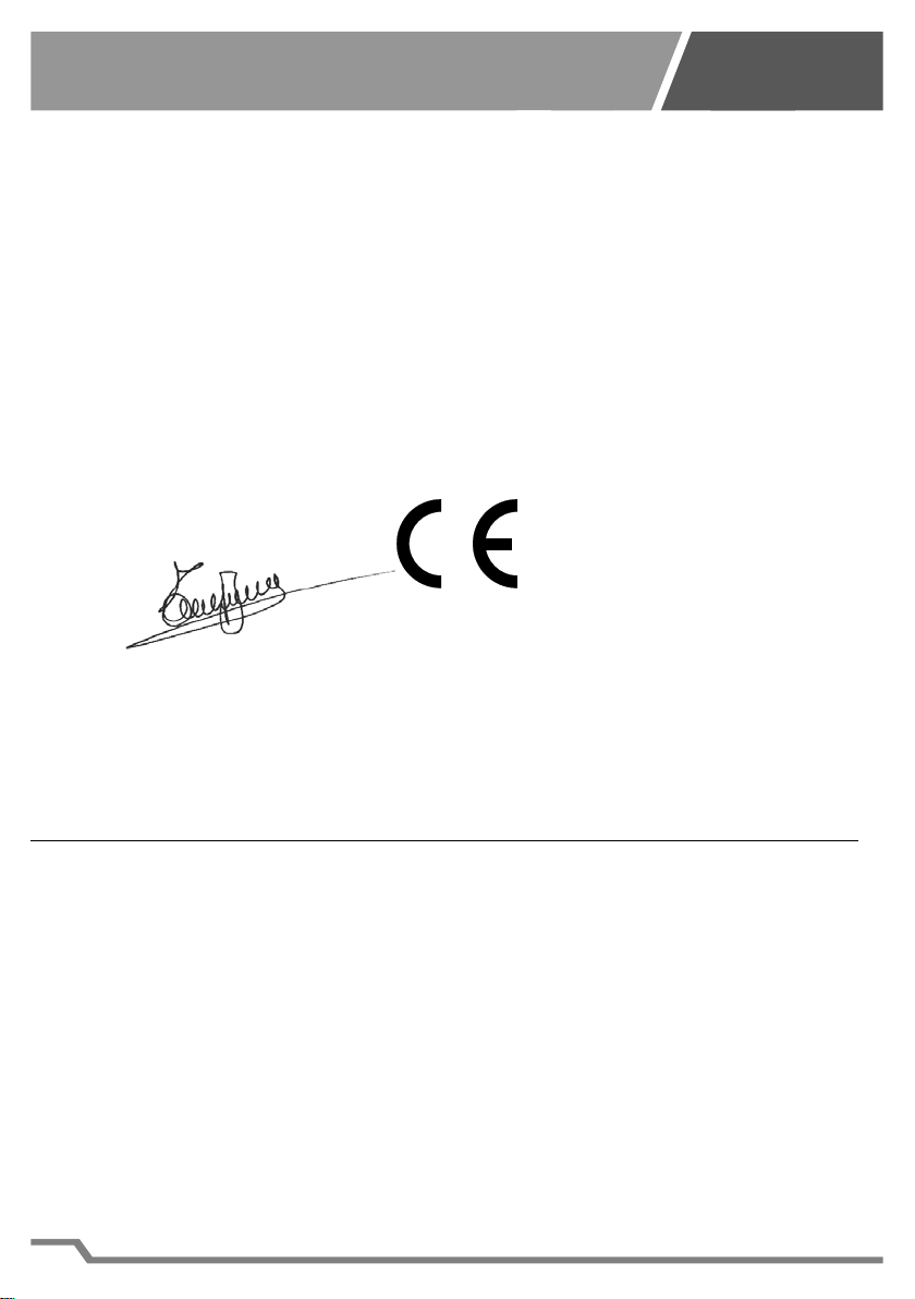
1.3 DICHIARAZIONE CE DI CONFORMITÀ
Via G. Ricci Curbastro, 8 - 48124 Fornace Zarattini, RAVENNA - C. F. / P. IVA 01075610392
DICHIARA SOTTO LA PROPRIA RESPONSABILITÀ CHE IL PRODOTTO NUOVO
AL QUALE QUESTA DICHIARAZIONE SI RIFERISCE È CONFORME ALLE SEGUENTI DISPOSIZIONI:
DIRETTIVA COMPATIBILITÀ ELETTROMAGNETICA 2004/108/CE
DIRETTIVA SICUREZZA BASSA TENSIONE 2006/95/CE
È STATO REALIZZATO SECONDO LE SEGUENTI NORME ARMONIZZATE:
Sicurezza Codice della Norma utilizzata: EN 60335 - 1 / EN 60335 - 2 - 55 E SUCCESSIVE MODIFICHE
Compatibilità Elettromagnetica Codice della Norma utilizzata: EN 61000-6-1 / EN 61000-6-3 E SUCCESSIVE
CHILLER LINE
LA SOTTOSCRITTA
TECO S.r.l. - TECNOLOGIE DI REFRIGERAZIONE
Sede Legale, Amministrativa e Commerciale:
MOD.: TK150
MODIFICHE
IT
Nome: Turci Bruno Via G. Ricci Curbastro, 8 - 48124 Fornace Zarattini, RAVENNA
Turci Bruno Ravenna 08/01/2014
Manager
1.4 TARGHETTA DI IDENTIFICAZIONE CE
Questo refrigeratore è stato prodotto in uno stato appartenente alla comunità europea, pertanto risponde ai
requisiti di sicurezza richiesti dalla direttiva macchine 2006/42/CE, in vigore dal 29 dicembre 2009.
Tale conformità è certifi cata e sul prodotto è presente la marcatura “CE”, posizionata sulla parte inferiore
dell’apparecchio (Rif. A3 Fig. 4).
2 PRESENTAZIONE DEL PRODOTTO
2.1 DESCRIZIONE DEL REFRIGERATORE
Il prodotto è idoneo per la refrigerazione dell’acqua contenuta in acquari di tipo domestico e/o commerciale.
È compatibile con l’acqua dolce o salata e alla vita di pesci, piante, rocce vive, ecc.. Il refrigeratore non deve
essere utilizzato per scopi diversi da quelli previsti e sopra specifi cati. Un utilizzo diverso da quello per cui il
prodotto è stata realizzato può causare condizioni di pericolo.
2.1.1 Contenuto della confezione
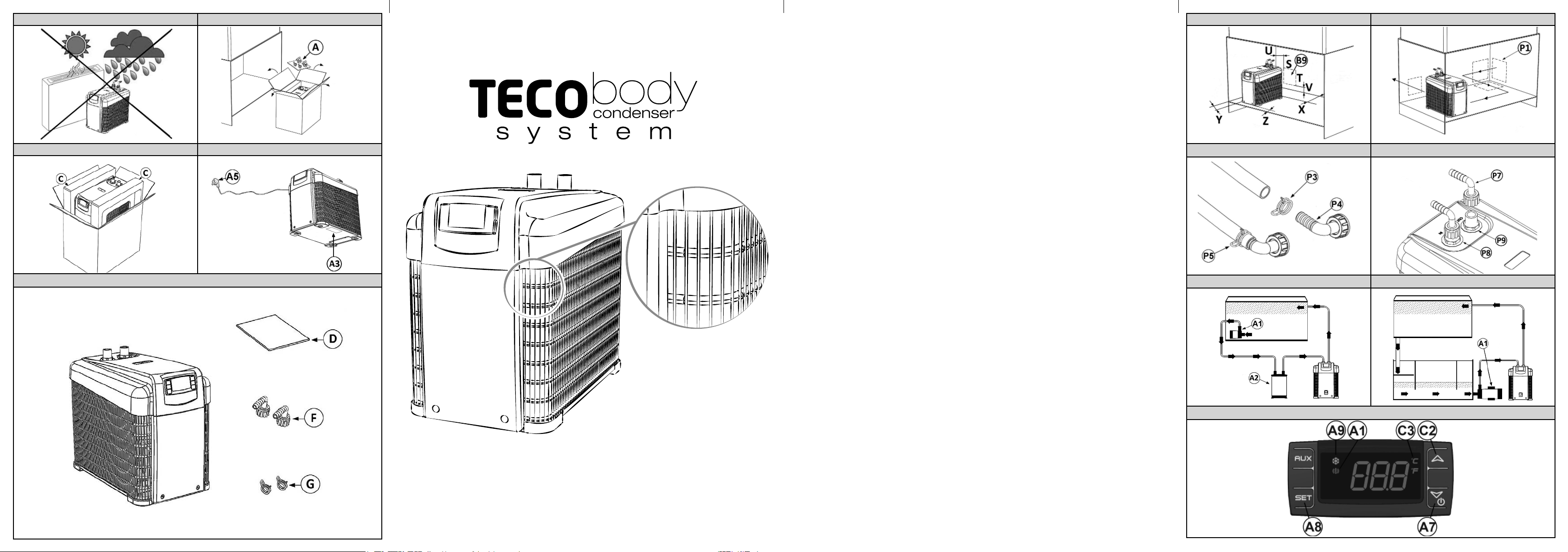
All’apertura della scatola di cartone controllare la presenza di tutti gli accessori (Fig. 5):
D Manuale istruzioni 1
F Raccordi di collegamento tubi completi di guarnizioni 2
G Fascette per bloccaggio tubi 2
Verifi care attraverso la targhetta dei dati tecnici (Rif. A3 Fig. 4) che l’apparecchio contenuto nell’imballo corrisponda al modello acquistato.
ager
La persona autorizzata a costituire la documentazione tecnica è:
2
Page 5
TANK
3 ORGANIZZAZIONE MANUALE/MODALITÀ DI CONSULTAZIONE
3.1 STRUTTURA DEL MANUALE
Il manuale è diviso in capitoli, che radunano per argomenti tutte le informazioni necessarie per utilizzare il prodotto senza alcun rischio.
3.2 DESCRIZIONE DEI PITTOGRAMMI
Sul manuale verranno utilizzati i seguenti simboli per evidenziare indicazioni ed avvertenze particolarmente
importanti:
ATTENZIONE: Questo simbolo indica norme antinfortunistiche per l’operatore e/o per eventuali
persone esposte.
AVVERTENZA: Questo simbolo indica che esiste la possibilità di arrecare danno al prodotto e/o
ai suoi componenti.
NOTA: Questo simbolo segnala informazioni utili.
4 DATI E CARATTERISTICHE TECNICHE
4.1 CARATTERISTICHE TECNICHE
Specifi che
Alimentazione
Potenza elettrica assorbita
(raff reddamento)
Entrata/uscita acqua 12 mm - 1/2 in
Flusso acqua minimo / massimo
Pressione massima 0,5 bar 7,25 PSI
Peso 12,2 kg - 26,9 lb
Dimensioni
Gas presente all’interno del
climatizzatore
Tutti i dati sono indicativi e possono essere variati senza preavviso da TECO.
L’apparecchio può contenere gas fl uorurati ad eff etto serra disciplinati dal protocollo di Kyoto.
Tipo di gas R134a valore GWP:1430
5 INSTALLAZIONE E FUNZIONAMENTO
5.1 DISIMBALLO DELL’APPARECCHIO
CHILLER LINE
Modello
TK 150
230V - 50Hz
230V - 60Hz
115V - 60Hz
190 W
300 l/h – 80 gal/h / 500 l/h – 132 gal/h
215 x 361 x 315 (h) mm
8,46 x 14,21 x 12,4 (h) in
Verifi care quale gas è presente nel modello acquistato vedi targhetta Rif. A3 Fig.4
Tab. 4-1
IT
AVVERTENZA: non capovolgere l’imballo o l’apparecchio. Conservare l’imballo integro per mo-
vimentazioni future.
1) Aprire l’imballo e togliere gli accessori (Rif. A Fig. 2).
2) Sfi lare il contenuto, senza ribaltarlo.
3) Togliere il polistirolo (Rif. C Fig. 3).
4) Togliere il sacchetto di plastica.
3
Page 6

TANK
5.2 INSTALLAZIONE E FUZIONAMENTO DELL’APPARECCHIO
1) Non installare o cercare di riparare il prodotto se questo ha subito danni durante il trasporto.
2) Non connettere il cavo di alimentazione alla presa elettrica se non quando specifi catamente richiesto.
3) Per garantire il corretto funzionamento dell’apparecchio in condizioni di sicurezza, è assolutamente vietato
esporlo agli agenti atmosferici e a fonti di calore dirette (Fig. 1). La temperatura nell’ambiente di installazione
deve essere compresa tra i 5 °C e i 38 °C (41 °F – 100 °F).
4) Se l’installazione è all’interno di un mobile provvedere ad eff ettuare l’apertura sulla parete scelta per l’evacuazione dell’aria calda, rispettando le distanze minime raccomandate (Fig. 6).
Posizione apertura evacuazione aria calda
S 150 mm – 5,91 in
T 150 mm – 5,91 in
U > 75 mm – 2,95 in
V 30 mm – 1,18 in
5) Provvedere, nella zona più bassa del mobile, ad una apertura di 400 cm
dell’aria all’interno del mobile (Rif. P1 Fig. 7).
6) Predisporre i tubi come segue:
6.1) Se necessario, infi lare la fascetta blocca tubo (Rif. P3 Fig. 8).
6.2) Infi lare il raccordo (Rif. P4 Fig. 8) nel tubo, e portare la fascetta blocca tubo sul raccordo (Rif. P5 Fig. 8).
6.3) Avvitare in senso orario il raccordo (Rif. P7 Fig. 9) orientandolo secondo le proprie necessità e stringere a
fondo.
6.4) Nel collegare i tubi, prestare attenzione che il tubo proveniente dalla pompa (non fornita) (Rif.A1 Fig.10-11)
e/o dal gruppo fi ltro (non forniti con l’apparecchio) (Rif.A2 Fig.10) sia collegato nella posizione indicata con
IN (Rif.P8 Fig.9), il tubo di ritorno all’acquario sia collegato nella posizione indicata con OUT (Rif.P9 Fig.9).
7) Sistemare l’apparecchio nel luogo scelto consentendo la visibilità dello strumento.
8) Mettere in funzione la pompa e assicurarsi che l’acqua circoli regolarmente all’interno del circuito e che non
vi siano perdite. In caso di anomalie del circuito idraulico o perdite dello stesso, rivedere le connessioni.
CHILLER LINE
Distanze minime dalle pareti
Z (Lato uscita aria) 0-10 mm – 0 - 0,39 in
X (Lato uscita cavo) 60 mm – 2,36 in
Y (Fianco) 50 mm – 1,97 in
Tab. 5-1
2
– 62 in2 per permettere l’ingresso
IT
9) AVVERTENZA: assicurarsi che l’acqua che arriva all’apparecchio sia fi ltrata.
10) Assicurarsi che le caratteristiche dell’alimentazione elettrica corrispondano a quelle riportate sulla targhetta
dei dati tecnici, applicata sul retro dell’apparecchio (Rif. A3 Fig. 4).
11) Con la pompa in funzione, inserire il cavo di alimentazione nella presa di corrente (Rif. A5 Fig. 4), sul display
comparirà la scritta OFF. Premendo il pulsante di accensione (Rif. A7 Fig. 12) per almeno 3 secondi, il
vostro apparecchio entrerà in funzione, sul display è indicata la temperatura dell’acqua. Per visualizzare la
temperatura da raggiungere premere il tasto SET (Rif. A8 Fig. 12), per tornare alla temperatura dell’acqua
premere nuovamente il tasto SET (Rif. A8 Fig. 12) o attendere 5 secondi.
12)
13) Per fermare l’apparecchio premere il pulsante di accensione (Rif. A7 Fig. 12) per almeno 3 secondi, sul
AVVERTENZA: per evitare guasti al compressore è stato previsto un ritardo di 2 minuti al
primo avviamento.
display comparirà la scritta OFF.
AVVERTENZA: L’apparecchio deve essere installato ad un’altezza inferiore al livello dell’acqua.
AVVERTENZA: Per evitare danni l’apparecchio non può funzionare senza la circolazione dell’ac-
qua (pompa spenta).
4
Page 7

TANK
5.2.1 Indicazioni presenti sul display
Acceso: apparecchio in funzione raff reddamento (Rif. A9 Fig. 12).
Acceso: apparecchio in funzione riscaldamento (Rif. B1 Fig. 12).
Lampeggiante: apparecchio pronto per il raff reddamento (Rif. A9 Fig. 12).
Lampeggiante: apparecchio pronto per il riscaldamento (Rif. B1 Fig. 12).
Acceso: condizione di allarme (Rif. A1 Fig. 12).
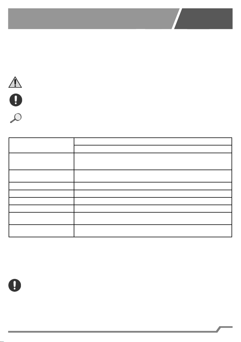
5.2.2 Regolazioni termostato
Fare riferimento alla fi gura 12 per l’individuazione dei pulsanti.
1) Per modifi care la temperatura dell’acqua:
a. Premere per 3 secondi il tasto SET (Rif. A8), viene visualizzato il valore attualmente impostato e l’icona
dell’unità di misura (C o F Rif. C3) inizia a lampeggiare.
b. Modifi care il valore utilizzando i tasti
c. Premere il tasto SET (Rif. A8) per confermare il valore impostato.
2)
Per regolare altri parametri: isteresi di funzionamento (Hy), calibrazione sonda (Ot), esclusione della resistenza (O1).
d. Accedere al menu di programmazione tenendo premuti per 3 secondi i tasti SET + (Rif. A8 e A7).
L’icona dell’unità di misura selezionata inizia a lampeggiare (C o F Rif. C3) e appare Hy
e. Scorrere i parametri con i tasti e (Rif. C2 e A7) fi no a visualizzare il parametro desiderato.
f. Premere il tasto SET (Rif. A8), viene visualizzato il valore attualmente impostato.
g. Modifi care il valore utilizzando i tasti e (Rif. C2 e A7).
h. Premere il tasto SET (Rif. A8) per confermare il valore impostato e passare al parametro successivo.
i. Premere SET + (Rif. A8 e C2) per uscire dalla programmazione.
NOTA: se non si preme nessun tasto per 30 secondi, tutti i valori impostati vengono memorizzati
e l’apparecchio si predispone per il funzionamento.
Parametro
Hy 1°C
Ot 0°C
o1 On
rL xx.x
Tab. 5-2
5.3 TRASPORTO ED IMMAGAZZINAMENTO
Il refrigeratore deve essere movimentato delicatamente in posizione verticale.
Va posizionato su una superfi cie piana.
5.4 DEMOLIZIONE E SMALTIMENTO
L’etichetta con il cassonetto barrato presente sul prodotto indica che il prodotto non deve essere smaltito tramite la procedura normale di smaltimento dei rifi uti domestici. Per evitare eventuali danni all’ambiente e alla salute umana, separare questo prodotto da altri rifi uti domestici in modo che possa venire riciclato in base alle procedure di rispetto ambientale. Per maggiori dettagli sui centri di raccolta disponibili, contattare l’uffi cio governativo locale o il rivenditore del prodotto.
Queste informazioni si applicano solo ai clienti dell’Unione europea, conformemente alla direttiva 2002/96/CE
del Parlamento europeo e del Consiglio del 27 Gennaio del 2003, sui rifi uti di apparecchiature elettriche ed elettroniche (RAEE) e le norme che ne sanciscono il recepimento e l’attuazione nei vari sistemi giuridici nazionali. Per altri paesi,
contattare il governo locale per studiare la possibilità di riciclare il vostro prodotto.
Valore
Preimpostato
CHILLER LINE
e (Rif. C2 e A7) (5 ÷ 35°C / 41 ÷ 95°F).
Descrizione
Questo parametro regola l’isteresi, cioè diff eren-
ziale di intervento dell’apparecchio.
Questo parametro regola la calibrazione della
sonda: permette di compensare la diff erenza di
temperatura letta sul display rispetto alla tempe-
ratura reale dell’acqua.
Attivazione/disattivazione funzione di riscaldamento. In questo modello la resistenza è assen-
te. Impostare solamente su “OFF”.
Versione fi rmware termostato.
Parametro in sola lettura.
IT
Intervallo di
regolazione
0,5 ÷ 10°C
1 ÷ 45°F
-12 ÷ 12°C
-20 ÷ 20°F
On - OFF
-
5
Page 8

TANK
6 MANUTENZIONE
6.1 MANUTENZIONE ORDINARIA
L’apparecchio non necessita di alcuna manutenzione ordinaria.
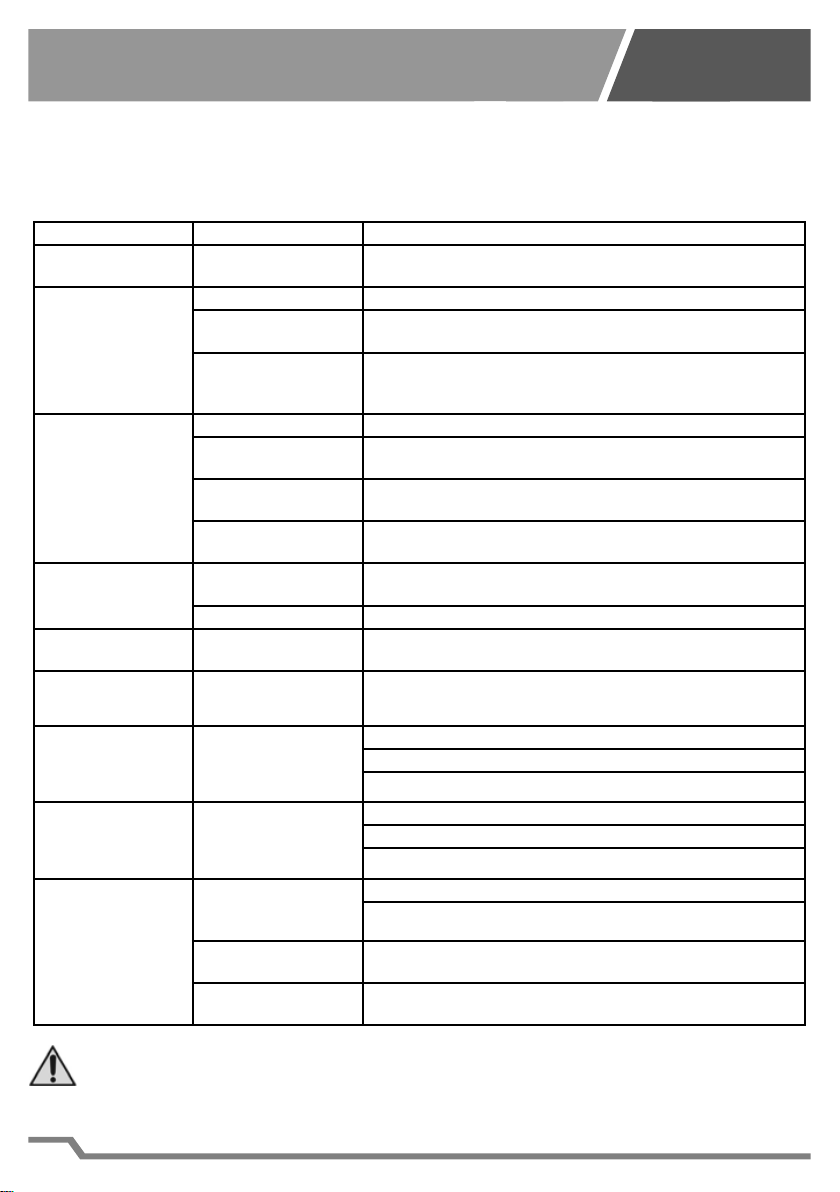
7 DIAGNOSTICA, INCONVENIENTI, CAUSE E RIMEDI
7.1 Tabella inconvenienti, cause e rimedi
Inconvenienti Cause Rimedi
Il display non si accende.
Scarso raff reddamento
dell’acqua.
Sul display compare
il messaggio “HA2”,
(surriscaldamento).
Scarso riscaldamento dell’acqua.
Sul display compare
il messaggio “P1”.
Sul display compare
il messaggio “P2”.
Sul display compare
il messaggio “HA”.
Sul display compare
il messaggio “LA”.
La temperatura visualizzata sul display
dell’apparecchio non
corrisponde a quella
eff ettiva dell’acquario.
ATTENZIONE: prima di scollegare l’apparecchio dalle tubazioni è necessario spegnere l’appa-
recchio e staccare tutte le spine elettriche delle apparecchiature collegate all’acquario.
L’operatore deve poter essere in grado di verifi care da tutte le posizioni cui ha accesso che la
spina resti disconnessa.
Provvedere inoltre a chiudere le tubazioni per evitare la fuoriuscita dell’acqua.
6
Mancanza di alimentazione elettrica.
Flusso acqua insuffi ciente.
Isolamento acquario
non suffi ciente
Aria in uscita dalla gri-
glia di ventilazione a
temperatura ambiente.
Filtro aria sporco. Pulire il fi ltro come indicato nel capitolo 6 Manutenzione.
Temperatura ambiente
troppo elevata.
Sistema di ventilazio-
ne ostruito.
Sistema di ventilazio-
ne guasto.
Flusso acqua insuffi -
ciente.
Resistenza guasta. Rivolgersi al rivenditore TECO S.r.l. di zona.
Guasto della sonda di
temperatura acqua.
Guasto della sonda di
surriscaldamento
Alta temperatura
dell’acqua.
Bassa temperatura
dell’acqua.
L’acqua non circola
correttamente all’interno del circuito idraulico.
Tubazioni lunghe e
non isolate.
Sonda termica non
tarata.
CHILLER LINE
Controllare che la spina sia inserita a fondo nella presa di
corrente (Rif. A5 Fig. 4).
Controllare il corretto funzionamento della pompa (non fornita).
Provvedere a isolare le pareti dell’acquario e le tubazioni per
ridurre le dispersioni termiche
Mancanza gas nel compressore, rivolgersi al rivenditore
TECO S.r.l. di zona.
Ripristinare le condizioni ambientali ottimali. La temperatura
ambiente massima consentita è di 38 °C (100 °F).
Liberare o pulire la griglia metallica e collocare il climatizzatore in ambiente idoneo.
Rivolgersi al rivenditore TECO S.r.l. di zona
Controllare il corretto funzionamento della pompa (non fornita) (Rif. A1 Fig. 12-13).
Rivolgersi al rivenditore TECO S.r.l. di zona.
Rivolgersi al rivenditore TECO S.r.l. di zona.
Controllare il corretto funzionamento della pompa (non fornita) (Rif. A1 Fig. 12-13).
Verifi care che non ci siano strozzature delle tubazioni.
Verifi care che la funzione di raff reddamento sia attiva.
Controllare il corretto funzionamento della pompa (non forni-
ta) (Rif. A1 Fig. 12-13).
Verifi care che non ci siano strozzature delle tubazioni.
Verifi care che la funzione di riscaldamento sia attiva (ove presente).
Verifi care eventuali strozzature delle tubazioni.
Verifi care l’effi cienza della pompa (non fornita).
Accorciare il più possibile le tubazioni e isolarle termicamente.
Tarare la sonda termica come indicato al paragrafo 5.2.2 Regolazioni Termostato.
Tab. 7-1
IT
Page 9

TANK
WARNING: This product is not suitable for children under 6 years.
It is essential to ensure that children do not play with the device.
This device is not intended for use by persons (including children) with limited physical, sensorial or mental abilities, or lacking in experience and know-how, unless supervision or instructions for using the device are provided by the person responsible for their safety.
Cleaning and maintenance shall not be made by children without supervision.
1 GENERAL INSTRUCTIONS AND INFORMATION FOR THE USER
1.1 INTRODUCTION
1.1.1 Important Notes
All rights of reproduction of this manual are reserved by TECO Srl. This manual cannot be inspected by a thirdparty without prior written authorization of TECO Srl
The text of this manual cannot be used in other printed matter without written authorization of TECO Srl.
Descriptions and illustrations in this publication are not binding, while the chiller and air conditioner ‘s essential
characteristics remain the same.
The manufacturer reserves the right to make any modifi cations considered appropriate to improve the product
or for requirements of a constructional or commercial nature, at any time and without undertaking to update this
publication immediately.
Please visit the website “www.tecoonline.eu/resources” for updated version of this manual.
THIS MANUAL IS PROPERTY OF TECO S.r.l. ANY REPRODUCTION, EVEN PARTIAL, IS PROHIBITED.
©TECO S.r.l.
NOTE: Please keep these instructions for future references.
1.1.2 Important Notes
• To avoid the possibility of personal injury from the rotating blades, never insert your fi ngers or any foreign
bodies into the air outlet grille.
• Do not scratch or pull the power source cord.
• If you detect any anomalies (such as a burning smell etc.) disconnect the power plug and contact your
dealer. Fire or breakage may occur if you continue to operate the unit under abnormal situation.
• If the power supply cord is damaged it must be replaced by the manufacturer, the dealer or a qualifi ed tech-
nician in order to avoid any hazard.
• Repair may be carried out only by qualifi ed persons. If this are not performed properly, they can cause elec-
tric shocks, burns and fi res.
• Make sure that the unit is unplugged from its power supply before performing any maintenance to the
aquarium.
• Do not expose the device to atmospheric agents or to direct heat sources. The device can be used within an
ambient temperature range of 5°C and 38°C (41°F - 100°F). Make sure that the power supply requirements
correspond to those indicated on the label “technical data” affi xed to the device (see related paragraph).
1.2 WARRANTY
The devices manufactured by TECO S.r.l. are covered by warranty by the dealer through them the product was
purchased from, as provided for in the laws of the country in which they are sold. If an equipment malfunction
or failure, listed in the warranty conditions, occurs during the validity period; after checking the unit, the authorized dealer will repair or replace defective parts. In order to obtain the recognition of the warranty it is necessary
to submit documentation required under the law of the country where the device is sold and under the dealer’s
conditions or conditions provided by the authorized service center TECO.
CHILLER LINE
EN
WARNING: Unauthorized modifi cations or repairs carried out by the user without written au-
thorization by TECO Srl will void the warranty and discharge TECO Srl from liability for damages
caused by defective products. The same considerations are valid if you use non-original spare
parts or other than those explicitly specifi ed by TECO Srl.
7
Page 10

TANK
1.3 DECLARATION OF CONFORMITY
TECO S.R.L. – REFRIGERATION TECHNOLOGIES
Via G. Ricci Curbastro, 8 - 48124 Fornace Zarattini, RAVENNA – Tax Code and VAT no. 01075610392
DECLARES, ASSUMING FULL RESPONSIBILITY, THAT THE NEW PRODUCT:
TO WHICH THIS DECLARATION REFERS COMPLIES WITH THE FOLLOWING PROVISIONS:
- ELECTROMAGNETIC COMPATIBILITY DIRECTIVE 2004/108/EC
IT HAS BEEN PRODUCED IN ACCORDANCE WITH THE FOLLOWING HARMONIZED STANDARDS:
Code of the Standard used: EN 60335 - 1 / EN 60335 - 2 - 55 AND SUBSEQUENT AMENDMENTS
Code of the Standard used: EN 61000 - 6 - 1 / EN 61000 - 6 - 3 AND SUBSEQUENT AMENDMENTS
CHILLER LINE
THE UNDERSIGNED
Legal, Administrative and Commercial Premises:
MOD.: TK150
- LOW VOLTAGE SAFETY DIRECTIVE 2006/95/EC
Safety
Electromagnetic Compatibility
EN
Name: Turci Bruno Via G. Ricci Curbastro, 8 - 48124 Fornace Zarattini, RAVENNA
Turci Bruno Ravenna 08/01/2014
Manager
1.4 EC IDENTITY PLATE
This chiller has been produced in a state belonging to the European community, therefore meets the safety
requirements of the Machinery Directive 2006/42/EC , in force since 29 December 2009.
This conformity is certifi ed and on the product there is the marking “CE “ , located on the bottom of the unit (
Ref. A3 Fig. 4).
2 PRODUCT OVERVIEW
2.1 DESCRIPTION OF THE CHILLER
The product is suitable for water chilling of the water contained in domestic and/or commercial aquariums. It is
compatible with fresh or salt water and with life of fi shes, plants, live rocks, etc. The chiller should not be used
for purposes other than those provided for and specifi ed above. Any other use than that for which the product
was made may cause hazardous conditions.
2.1.1 Package Contents
Open the box and verify that the following accessories are present (Fig. 5):
D Instruction Manual 1
F Pipe connection fi ttings (including gaskets) 2
G Cable-tie-wrap 2
Check the technical plate of the unit (Ref. A3 Fig. 4) to make sure that the device contained in the package
matches the model you purchased.
The person authorized to draw up this statement:
8
Page 11

TANK
3 MANUAL ORGANIZATION AND CONSULTATION MODE
3.1 MANUAL STRUCTURE
The manual is divided into chapters, each corresponding to main topics, that provide
information required to use the product without any risk.
3.2 DESCRIPTION OF PICTOGRAPHS
In this manual the following symbols are used to highlight specifi c information and warnings:
WARNING: This symbol indicates safety regulations for the operator and/or for people who may
be exposed.
CAUTION: This symbol indicates that there is a possibility of damage to the product and/or its
components.
NOTES: This symbol indicates useful information
4 TECHNICAL DATA AND SPECIFICATIONS
4.1 TECHNICAL FEATURES
Specifi cations
Supply
Power consumption (cooling) 190 W
Water inlet / outlet 12 mm - 1/2 in
Minimum / maximum fl ow rate 300 l/h – 80 gal/h / 500 l/h – 132 gal/h
Maximum Pressure 0,5 bar 7,25 PSI
Weight 12,2 kg - 26,9 lb
Dimensions
Gas inside the conditioner Verify which gas is present in the model purchased (see plate) Rif. A3 Fig. 4
All data are approximate and may be changed without notice by TECO.
The device can contain fl uorinated greenhouse gases covered by the Kyoto Protocol.
Type R134a GWP: 1430
5 INSTALLATION AND OPERATION
5.1 UNPACKING OF THE DEVICE
CHILLER LINE
Model
TK 150
230V - 50Hz
230V - 60Hz
115V - 60Hz
215 x 361 x 315 (h) mm
8,46 x 14,21 x 12,4 (h) in
Tab. 4-1
EN
CAUTION: do not turn upside down neither the packaging nor the appliance. Keep the packag-
ing box and materials for future movement or transport.
1) Open the packaging and remove the accessories (Rif. A Fig. 2).
2) Pull out the device grasping side handles.
3) Remove the polystyrene (Rif. C Fig. 3).
4) Remove the plastic bag.
9
Page 12
TANK
5.2 INSTALLATION AND FUNCTIONING OF THE DEVICE
1) Do not install and do not try to repair the product if it was damaged during transport.
2) Do not connect the power cord to the power supply, unless specifi cally required.
3) In order to ensure the correct working of the device in safe conditions, it is absolutely forbidden to expose
the product to atmospheric agents and to direct heat sources (Fig. 1). The temperature of the installation
environment has to be between 5 °C and 38 °C (41 °F – 100 °F).
4) If the device is installed inside a cabinet, open the selected wall for warm air output, while respecting the
recommended minimum distance (Fig. 6).
Opening position hot air outlet
S 150 mm – 5,91 in
T 150 mm – 5,91 in
U > 75 mm – 2,95 in
V 30 mm – 1,18 in
5) In the lower area of the cabinet provide for an opening of 400 cm
the cabinet (Ref. P1 Fig. 7).
6) Lay the tubes as follows:
6.1) If necessary, insert cable-tie-wrap (Ref. P3 Fig. 8).
6.2) Insert the joint ( Ref. P4 Fig. 8) in the tube, and bring cable-tie-wrap on the joint ( Ref P5 Fig. 8).
6.3) Fasten the joint clockwise (Ref. P7 Fig. 9), direct it as needed and tighten it.
6.4) When connecting the pipes, make sure that the hose from the pump (not supplied) (Ref. A1 Fig. 10-11 ) and
/ or the fi lter assembly (not supplied with the unit) (Ref.A2 Fig. 10) is connected in the position indicated with
IN (Ref. P8 Fig. 9), the return pipe is connected to the aquarium in the position indicated with OUT (Ref.P9
Fig.9).
7) Install the unit in the chosen place allowing the visibility of the equipment.
8) Start the pump, make sure that the water fl ows regularly in the circuit and that there are no leaks. In the case
of anomalies or leakage in the hydraulic circuit, review the connections.
CHILLER LINE
Minimum distance from walls
Z (air outlet side) 0-10 mm – 0 - 0,39 in
X (side cable exit) 60 mm – 2,36 in
Y (Lateral side) 50 mm – 1,97 in
Tab. 5-1
2
- 62 in2 to allow the entrance of air inside
EN
9)
10) Make sure that the power supply requirements match those shown on the technical plate, visible on the back
11) When the aquarium pump is functioning, connect the cable power supply to the power socket with the plug
Pressing the power button (Ref. A7 Fig. 12) for at least 3 seconds, your device will start working, on the
12)
13) To stop the device, press the power button (Ref. A7 Fig. 12) for at least 3 seconds, the display will show OFF.
CAUTION: Make sure that the water that reaches the device is fi ltered.
of the unit (Ref. A3 Fig. 4).
(Ref. A5 Fig. 4). Then, the display will show OFF.
display it is indicated the actual water temperature. To display the temperature to be reached press the SET
button (Ref.A8 Fig. 12) to return to the water temperature press the SET button (Ref.A8 Fig. 12) or wait for
5 seconds.
CAUTION: A 2-minutes delay was added to prevent compressor failure at the fi rst start.
CAUTION: The appliance must be installed at a height below the water level.
CAUTION: To prevent damages, the unit cannot operate without water fl ow (pump off ).
10
Page 13

TANK
5.2.1 Information on the display
On: unit in cooling mode (Ref. A9 Fig. 12).
On: unit in heating mode (Rif. B1 Fig. 12).
Flashing light: unit ready for cooling (Rif. A9 Fig. 12).
Flashing light: unit ready for heating (Rif. B1 Fig. 12).
On: alarm condition (Rif. A1 Fig. 12).
5.2.2 Thermostat settings
Refer to fi gure 12 for buttons detection.
1) To change the temperature of the water:
a. Push the button SET for 3 seconds (Rif. A8), display shows the current value setting and the unit of
measure icon (C or F ref C3) starts to blinking.
b. Modify the parameters using the arrows
c. Push the button SET (Rif. A8) to confi rm the values.
2) To adjust other parameters: hysteresis function (Hy), probe calibration (Ot), exclude the heater (O1):
d. Access to the programming menu by pressing the SET+ button for 3 seconds (Ref. A7 and A8). The
icon unit selected starts blinking (C or F ref C3) and appears Hy.
e.
Scroll through the parameters using the arrows and (Ref.C2 and A7) until the desired parameter.
f. Press the SET button (ref A8), the current set value is displayed.
g. Change the value using the arrows and (Rif. C2 and A7).
h. Press the SET button (Ref. A8) to confi rm the setting and move to the next parameter.
i. Press SET + (Ref. A8 and C2) to exit programming mode.
NOTE: If you do not press any buttons for 30 seconds, all settings are saved and the device is
ready for operation.
Parameter Preset value Description Regulation range
Hy 1°C
Ot 0°C
o1 On
rL xx.x
Tab. 5-2
5.3 TRANSPORTATION AND STORAGE
The chiller must be handled carefully in a vertical position.
It is recommended to place it on a fl at surface.
5.4 DEMOLITION AND DISPOSAL
ROPEAN PARLIAMENT and THE COUNCIL OF 27January 2003 on waste electrical and electronic equipment (WEEE) and
legislation transposing and implementing it info the various notional legal systems. For other countries, please contact your local
government to investigate the possibility of recycling your product.
The crossed-out wheelie bin label that can be found on your products, indicates that the product may not be
treated as household waste. By ensuring that this product is disposed of correctly, you will help preventing potential negative consequences for the environment and human health, which could otherwise be caused by inappropriate waste handling of these products. For more detailed information about recycling of this product, please
contact your local city offi ce, your household waste disposal or the dealer where you purchased this product.
This information only applies to customers in the European Union, according to Directive 2002/96/EC of EU-
CHILLER LINE
and (Rif. C2 and A7) (5 ÷ 35°C / 41 ÷ 95°F).
This parameter sets the hysteresis, that is the
diff erential of the unit.
This parameter adjusts the probe calibration: it
allows to compensate for the diff erence in temperature reading on the display with respect to
the actual water temperature.
Activation / deactivation of the heating function:
In this model, the resistance is absent.
Just set it to “OFF”.
Firmware version of thermostat.
Read-only parameter.
EN
0,5 ÷ 10°C
1 ÷ 45°F
-12 ÷ 12°C
-20 ÷ 20°F
On - OFF
-
11
Page 14
TANK
6 MANTAINANCE
6.1 ROUTINE MAINTENANCE
The device does not require any routine maintenance.
7 DIAGNOSTICS, PROBLEMS, CAUSES AND REMEDIES
7.1 Disadvantages, causes and remedies table
Disadvantages Causes Remedies
Display does not
light up.
Insuffi cient water
cooling.
On the display appears the message
“HA2” (overheating).
Insuffi cient water
heating.
On the display appears
the message “P1”.
On the display appears
the message “P2”.
On the display appears the message
“HA”.
On the display appears the message
“LA”.
The temperature displayed is not the real
one.
WARNING: Before you unplug the machine from the pipes it is necessary to turn off the device
and unplug all electrical plugs from the equipment connected to the aquarium.
Make sure that the operator can check from any point he has access that the plug remains disconnected.
Close also the pipes to prevent water leakage.
No electricity
Insuffi cient water fl ow.
Aquarium isolation is
not enough.
Outgoing air from
the ventilation grid at
room temperature.
Dirty air fi lter.
Ambient temperature
is too high.
Ventilation system
clogged.
Broken ventilation
system.
Insuffi cient water fl ow.
Defective heater. Contact the TECO S.r.l area retailer.
Damage of the water’s
temperature probe.
Damage of the over-
heating temperature
probe.
High water temperature.
Low water temperature.
The water does not circulate correctly inside
the hydraulic circuit.
Long and not insulated
pipes.
Temperature sensor
not calibrated correctly.
CHILLER LINE
Check if the power supply plug is fully inserted into the power
outlet (Rif. A5 Fig. 4).
Check the proper operation of the pump (not supplied) (Rif.A1 Fig.12-13).
Insulate the walls of the aquarium and the pipes to reduce
heat loss.
Lack of gas in the compressor, contact the TECO S.r.l area
retailer.
Clean the air fi lter following the instruction (Chapter 6 Maintenance).
Restore the optimal environmental conditions.
The maximum ambient temperature allowed is 38°C (100°F).
Free up or clean the metal grid or place the chiller in an ap-
propriate environment .
Contact the TECO S.r.l area retailer.
Check the correct operation of the pump (not supplied) (Rif.
A1 Fig. 12-13).
Contact the TECO S.r.l area retailer.
Contact the TECO S.r.l area retailer.
Check the proper operation of the pump (not supplied) (Rif.A1 Fig.12-13).
Check that there are no crimps in the tubing.
Check that the cooling function is activated.
Check the proper operation of the pump (not supplied) (Rif.A1 Fig.12-13).
Check that there are no crimps in the tubing.
Check that the heating function is activated (if present).
Check eventually pipes obstructions.
Check the effi ciency of the aquarium’s pump (not supplied).
Reduce as much as possible the pipes and insulate them.
Calibrate the temperature sensor as described in paragraph
5.2.2 Thermostat Settings.
Tab. 7-1
EN
12
Page 15
TANK
ATTENTION: ce produit n’est pas adapté aux enfants de moins de six ans.
Garder les enfants sous surveillance pour s’assurer qu’ils ne jouent pas avec l’appareil.
Cet appareil n’est pas destiné à être utilisé par des personnes (y compris les enfants) aux capacités physiques, sensorielles ou mentales réduites, ou manquant d’expérience et de connaissance, à moins d’être supervisées ou instruites quant à l’utilisation de l’appareil par une personne responsable de leur sécurité.
Le nettoyage et l’entretien ne doivent pas être faits par des enfants sans surveillance.
1 AVERTISSEMENTS GENERAUX ET INFORMATIONS POUR L’UTILISATEUR
1.1 INTRODUCTION
1.1.1 Avertissements importants
Tous les droit de reproduction du présent mode d’emploi sont réservés à la société TECO S.r.l.. Ce guide d’utilisation ne peut en aucun cas être cédé à un tiers sans autorisation préalable écrite de TECO S.r.l.. Le texte ne
peut pas être utilisé dans d’autres publications sans une autorisation écrite de TECO S.r.l..
Les descriptions et les illustrations contenues dans cette publication ne sont pas contraignantes, étant toutefois entendu que les caractéristiques essentielles concernant le modèle de réfrigérateur ou de climatiseur
décrits restent les mêmes. La société se réserve le droit d’apporter les changements qu’elle jugera nécessaires
afi n d’améliorer ses produits, que cela soit pour des exigences techniques ou commerciales, à n’importe quel
moment et sans pour cela s’engager à mettre immédiatement à jour la présente publication.
La version mise à jour de ce manuel est disponible à l’adresse «www.tecoonline.eu/resources».
CE MANUEL EST UNE PROPRIÉTÉ DE LA SOCIETE TECO S.r.l. TOUTE REPRODUCTION MEME PARTIELLE EST INTERDITE. © TECO S.r.l.
NOTE: Gardez le manuel pour toute référence future.
1.1.2 Avertissements importants
• Ne pas insérer les doigts ou d’autres corps étrangers à l’intérieur des grilles d’air. Cela pourrait causer des
accidents dus à la rotation des pales.
• Ne pas rayer ou tirer le câble d’alimentation.
• Si une anomalie ce produit (par exemple si vous détectez une odeur de brûlé), déconnecter l’alimentation
et contacter le revendeur. Si l’unité reste en marche en dépit des anomalies, des ruptures ou des incendies
etc. peuvent se produire.
• Si le cordon d’alimentation est endommagé, il doit être remplacé par le constructeur, son agent de service
ou outre personne qualifiée, afin d’éviter tout danger.
• Les réparations ne doivent pas être eff ectuées par l’utilisateur mais seulement par du personnel technique.
Si les réparations ne sont pas eff ectuées correctement, il subsiste des risques d’incendie ou de choc électrique.
• Débrancher l’appareil de l’alimentation avant d’eff ectuer toute intervention pour l’entretien de l’aquarium.
• Ne pas exposer aux agents atmosphériques ou à des sources de chaleur directes. L’appareil peut être
utilisé à une température ambiante comprise entre 5 °C et 38 °C (41 °F – 100 °F). S’assurer que les caractéristiques de l’alimentation électrique correspondent à celles indiquées sur l’étiquette «données techniques»
se trouvant sur l’appareil (voir la section concernée).
1.2 GARANTIE
Les appareils produits par la TECO S.r.l. sont sous GARANTIE de la part du revendeur agréé auprès duquel
l’appareil a été acheté, comme prévu par les dispositions juridiques du pays où il a été acheté. Si pendant la
période de validité de la garantie, des défauts ou des dysfonctionnements couverts par la garantie apparaissent,
le revendeur agrée - après les opérations de vérifi cations - s’occupera de réparer ou de remplacer les parties
défectueuses. Pour faire valoir la garantie il est nécessaire de présenter la documentation prévue par les lois du
pays ou se vend l’appareil, et aux conditions prévues par le revendeur ou le centre d’assistance autorisé TECO.
CHILLER LINE
FR
ATTENTION:
S.r.l. fait déchoir la garantie et soulève TECO S.r.l. de toute responsabilité pour des dommages causés par la défectuosité du produit. Les mêmes considérations sont valables si on utilise des pièces
de rechange non originales ou diff érentes de celles explicitement indiquées par TECO S.r.l..
toute modifi cation apportée par l’utilisateur sans autorisation écrite de la part de TECO
13
Page 16

TANK
q
1.3 DECLARATION DE CONFORMITÉ
TECO S.R.L. – TECHNOLOGIES DE REFRIGERATION
Via G. Ricci Curbastro, 8 - 48124 Fornace Zarattini, RAVENNA - Code T.V.A. 01075610392
DECLARE SOUS SA PROPRE RESPONSABILITE QUE LE NOUVEAU PRODUIT :
AUQUEL SE REFERE CETTE DECLARATION EST CONFORME AUX DISPOSITIONS SUIVANTES:
- DIRECTIVE SUR LA COMPATIBILITE ELECTROMAGNETIQUE 2004/108/CE
- DIRECTIVE BASSE TENSION (SECURITE DES APPAREILS ELECTRIQUES) 2006/95/CE
A ETE REALISE CONFORMEMENT AUX NORMES HARMONISEES SUIVANTES:
Code de la Norme Utilisée: EN 60335 - 1 / EN 60335 - 2 - 55 ET MODIFICATIONS SUCCESSIVES
Code de la Norme Utilisée: EN 61000 - 6 - 1 / EN 61000 - 6 - 3 ET MODIFICATIONS SUCCESSIVES
CHILLER LINE
LA SOUSSIGNEE
Siège Légal, Administratif et Commercial:
MOD.: TK150
Sécurité
Compatibilité Electromagnétique
FR
Turci Bruno Via G. Ricci Curbastro, 8 - 48124 Fornace Zarattini, RAVENNA
Turci Bruno Ravenna 08/01/2014
Administrateur unique
1.4 ÉTIQUETTE D’IDENTIFICATION CE
Ce réfrigérateur a été produit dans un pays appartenant à la communauté européenne et satisfait aux conditions
de sécurité requises par la directive machines 2006/42/CE, en vigueur depuis le 29 décembre 2009.
Cette conformité est certifi ée par le marquage «CE» situé sur la partie inférieure du produit (Rif. A3 Fig. 4).
2 PRÉSENTATION DU PRODUIT
2.1 DÉSCRIPTION DU RÉFRIGÉRATEUR
Le produit est adapté à la réfrigération de l’eau contenue dans les aquariums à usage domestique et/ou commercial. Il est compatible avec l’eau douce ou salée et avec la vie de poissons, plantes, roches vives, etc. Le
réfrigérateur ne doit pas être utilisé pour des fi nalités diff érentes de celles prévues et susmentionnées. Un emploi diff èrent de celui pour lequel le produit a été conçu peut déterminer des conditions de danger.
2.1.1 Contenu de l’emballage
À l’ouverture de la boite de carton, contrôler que tous les accessoires sont bien présents (Fig. 5):
D Mode d’emploi 1
F Raccords de liaison tubes avec joints 2
G Colliers serre-tubes 2
Se servir de l’étiquette des données techniques (Rif. A3 Fig. 4) pour vérifi er que l’appareil à l’intérieur de l’emballage correspond au modèle acheté.
La personne autorisée à rédiger la présente déclaration :
14
Page 17
TANK
3 ORGANISATION MODE D’EMPLOI/MODES DE CONSULTATION
3.1 STRUCTURE DU MODE D’EMPLOI
Ce mode d’emploi est divisé en chapitres qui rassemblent par sujets toutes les informations nécessaires pour
se servir du produit sans prendre aucun risque.
3.2 DESCRIPTION DES PICTOGRAMMES
Les suivants symboles seront utilisés dans ce mode d’emploi pour attirer l’attention sur les indications et les
avertissements particulièrement importants:
ATTENTION: Ce symbole indique les règles de sécurité du travail pour l’opérateur et/ou pour les
personnes éventuellement exposées.
AVERTISSEMENT : Ce symbole indique qu’il existe une possibilité d’endommager le produit et/
ou ses composants.
NOTE: Ce symbole indique les informations utiles.
4 DONNÉES TECHNIQUES ET SPÉCIFICATIONS
4.1 CARACTÉRISTIQUES TECHNIQUES
Spécifi cations
Alimentation
Puissance électrique absorbée
(refroidissement)
Entrée/Sortie de l’eau 12 mm - 1/2 in
Débit eau min / max 300 l/h – 80 gal/h / 500 l/h – 132 gal/h
Pression max. 0,5 bar 7,25 PSI
Poids 12,2 kg - 26,9 lb
Dimensions
Gaz présents à l’intérieur du climatiseur
Toutes les données sont approximatives et peuvent être modifi ées sans préavis par TECO.
L’appareil peut contenir des gaz fl uorés à eff et de serre, selon les règles défi nies par le Protocol de Kyoto.
Type de gaz R134a valeur GWP:1430
5 INSTALLATION ET FONCTIONNEMENT
5.1 DÉBALLAGE DE L’APPAREIL
CHILLER LINE
Model
TK 150
230V - 50Hz
230V - 60Hz
115V - 60Hz
190 W
215 x 361 x 315 (h) mm
8,46 x 14,21 x 12,4 (h) in
Vérifi er le type de gaz présent dans le modèle acheté (voir l’étiquette Rif. A3 Fig. 4)
Tab. 4-1
FR
AVERTISSEMENT : ne pas retourner ni l’emballage ni l’appareil. Ne pas abîmer l’emballage afi n
de pouvoir le réutiliser à l’avenir.
1) Ouvrir l’emballage et enlever les accessoires (Rif. A Fig. 2).
2) Sortir le contenu, sans le retourner.
3) Enlever le polystyrène (Rif. C Fig. 3).
4) Enlever le sac en plastique.
15
Page 18

TANK
5.2 INSTALLATION ET FONCTIONNEMENT DE L’APPAREIL
1) Ne pas installer ou essayer de réparer le produit si ce dernier a été endommagé pendant le transport.
2) Ne pas connecter le câble d’alimentation à la prise électrique, sauf quand expressément indiqué.
3) Pour garantir un correct fonctionnement de l’appareil dans des conditions de sécurité, il est absolument
interdit de l’exposer aux agents atmosphériques et aux sources de chaleur directes (Fig. 1). La température
dans les locaux où est installé l’appareil doit être comprise entre 5 °C et 38 °C (41 °F – 100 °F).
4) Si l’installation s’eff ectue à l’intérieur d’un meuble, réaliser une ouverture sur la paroi choisie pour l’évacuation de l’air chaud, en respectant les distances minimales recommandées (Fig. 6).
Position ouverture évacuation air chaud
S 150 mm – 5,91 in
T 150 mm – 5,91 in
U > 75 mm – 2,95 in
V 30 mm – 1,18 in
5) Dans la partie la plus basse du meuble, réaliser une ouverture de 400 cm
de l’air à l’intérieur du meuble (Rif. P1 Fig. 7).
6) Placer les tuyaux de la manière suivante :
6.1) Si nécessaire, insérer le collier serre-tube (Rif. P3 Fig. 8).
6.2) Insérer le raccord (Rif.P4 Fig.8) dans le tube, et faire glisser le collier serre-tube sur le raccord (Rif.P5 Fig.8).
6.3) Visser dans le sens horaire le raccord (Rif. P7 Fig. 9) en le réglant dans la direction choisie et bien serrer.
6.4) Lors de la connexion des tuyaux, s’assurer que le tube provenant de la pompe (Rif. A1 Fig. 10-11) et/ou du
groupe fi ltre (Rif. A2 Fig. 10) (aussi bien la pompe que le groupe fi ltre ne sont pas fournis avec l’appareil) est
bien relié dans la position indiquée avec IN (Rif. P8 Fig. 10) et que le tube du retour à l’aquarium est relié
dans la position indiquée avec OUT (Rif. P9 Fig. 10).
7) Placer l’appareil à l’endroit choisi, tout en assurant la visibilité du produit.
8) Mettre en marche la pompe, s’assurer que l’eau circule régulièrement à l’intérieur du circuit et qu’il n’y a pas
de fuites. En cas d’anomalies du circuit hydraulique o de fuites, contrôler les connexions.
CHILLER LINE
Distances min. des parois
Z (Côté sortie air) 0-10 mm – 0 - 0,39 in
X (Côté sortie câble) 60 mm – 2,36 in
Y (Côté) 50 mm – 1,97 in
Tab. 5-1
2
– 62 in2 afi n de permettre l’entrée
FR
9) ATTENTION: s’assurer que l’eau qui arrive à l’appareil soit fi ltrée.
10) S’assurer que les caractéristiques de l’alimentation électrique correspondent à celles indiquées sur l’étiquette des données techniques, visible sur la partie postérieure de l’appareil (Rif. A3 Fig. 4).
11) Avec la pompe en marche, insérer la câble d’alimentation dans la prise de courant (Rif. A5 Fig. 4), sur l’affi cheur apparaitra le message OFF. En appuyant sur le bouton d’allumage (Rif. A7 Fig. 12) pour au moins 3
secondes, l’appareil se mettra en marche et sur l’affi cheur il sera possible de lire la température de l’eau.
Pour visualiser la température à atteindre, appuyer sur la touche SET (Rif. A8 Fig. 12), pour revenir à la
visualisation de la température de l’eau, appuyer à nouveau la touche SET (Rif. A8 Fig. 12) ou attendre 5
secondes.
12) ATTENTION: un retard de 2 minutes lors du premier allumage a été prévu afi n d’éviter d’éven-
tuelles pannes du compresseur.
13) Pour arrêter l’appareil appuyer le bouton d’allumage (Rif. A7 Fig. 12) pour au moins 3 secondes, sur l’affi cheur apparaitra le message OFF.
ATTENTION: L’appareil doit être installé à une hauteur inférieure au niveau de l’eau.
ATTENTION: Pour éviter des dommages, l’appareil ne doit pas être mis en marche sans circula-
tion d’eau (pompe éteinte).
16
Page 19

TANK
5.2.1 Indications de l’affi cheur
Accès: appareil en fonction refroidissement (Rif. A9 Fig. 12).
Accès: appareil en fonction chauff age (Rif. B1 Fig. 12).
Clignotant: appareil prêt pour le refroidissement (Rif. A9 Fig. 12).
Clignotant: appareil prêt pour le chauff age (Rif. B1 Fig. 12).
Accès: condition d’alarme (Réf. A1 Fig. 12).
5.2.2 Réglages thermostat
Faire référence à l’illustration 12 pour repérer les boutons.
1) Pour modifi er la température de l’eau :
a. Appuyer pendant 3 secondes la touche SET (Rif. A8) pour visualiser la valeur sélectionnée et l’icône de
l’unité de mesure (C ou F Rif. C3) commence à clignoter.
b. Modifi er la valeur en utilisant les touches
c. Appuyer la touche SET (Rif. A8) pour confi rmer la valeur sélectionnée.
2)
Pour régler d’autres paramètres : hystérésis de fonctionnement (Hy), réglage sonde (Ot), exclusion de la résistance (O1).
d.
Accéder au menu de programmation en appuyant pendant 3 secondes les touches SET + (Rif. A8 e A7).
L’icône de l’unité de mesure sélectionnée commence à clignoter (C ou F Rif. C3) et le symbole Hy apparait.
e.
Se déplacer dans la liste des paramètres à l’aide des touches et (Rif. C2 e A7) jusqu’à visualiser le paramètre souhaité.
f. Appuyer la touche SET (Rif. A8) pour visualiser la valeur actuellement sélectionnée.
g. Modifi er la valeur en se servant des touches et (Rif. C2 e A7).
h.
Appuyer la touche SET (Rif. A8) pour confi rmer la valeur sélectionnée et passer au paramètre successif.
i. Appuyer SET + (Rif. A8 e C2) pour sortir de la programmation.
NOTE : Au bout de 30 secondes sans appuyer sur aucune touche les valeurs réglées sont enre-
gistrées et l’appareil est prêt à fonctionner.
Paramètre
Hy 1°C
Ot 0°C
o1 On
rL xx.x
Tab. 5-2
5.3 TRANSPORT ET STOCKAGE
Le réfrigérateur doit être manié délicatement en position verticale.
Il est nécessaire de le placer sur une surface plate.
5.4 DÉMOLITION ET ÉLIMINATION
L’étiquette avec la benne à ordures barrée qui se trouve sur le produit indique que le produit ne doit pas être éliminé comme les autres déchets domestiques. Pour éviter tout risque de pollution environnementale ou d’atteinte
à la santé humaine, il est fortement recommandé de séparer ce produit des autres déchets domestiques pour qu’il
puisse être recyclé selon les normes de respect de l’environnement. Pour plus de détails sur les centres de collecte disponibles, contacter le bureau gouvernemental local ou le détaillant du produit.
Cette information s’applique exclusivement aux clients de l’Union Européenne, conformément à la directive
2002/96/CE du Parlement européen et du Conseil du 27 Janvier 2003 en matière de déchets d’équipements électriques et électroniques (RAEE) et les normes qui en assure la transposition et l’application dans les diff érents systèmes juridiques nationaux.
Pour les autres pays, contactez le gouvernement local pour étudier la possibilité de recycler votre produit.
Valeur
sélectionnée
CHILLER LINE
et (Rif. C2 e A7) (5 ÷ 35°C / 41 ÷ 95°F).
Description
Ce paramètre règle l’hystérésis, c’est-à-dire le
diff érentiel d’intervention de l’appareil.
Ce paramètre sert au réglage de la sonde : il permet de compenser la diff érence de température
entre celle indiquée sur l’affi cheur et la tempéra-
ture réelle de l’eau.
Activation/désactivation résistance de chauff age :
Sur ce modèle la résistance est absente; sélectionner “OFF”.
Version fi rmware thermostat.
Paramètre en lecture uniquement.
FR
Intervalle de
réglage
0,5 ÷ 10°C
1 ÷ 45°F
-12 ÷ 12°C
-20 ÷ 20°F
On - OFF
-
17
Page 20

TANK
6 ENTRETIEN
6.1 ENTRETIEN DE ROUTINE
L’appareil ne nécessite pas d’entretien de routine.
7 DIAGNOSTIQUE, PROBLÈMES, CAUSES AND REMÈDES
7.1 Tableau des inconvénients, des causes et des remèdes
Inconvénients Causes Remèdes
L’affi cheur ne s’allume pas.
Refroidissement insuffi sant de l’eau
Sur l’affi cheur apparait le message
“HA2” (surchauff e).
Chauff age de l’eau
insuffi sant
Sur l’affi cheur apparait le message “P1”.
Sur l’affi cheur apparait le message “P2”.
Sur l’affi cheur apparait le message “HA”.
Sur l’affi cheur apparait le message “LA”.
La température indiquée sur l’affi cheur
de l’appareil ne correspond pas à la
température réelle
de l’aquarium.
ATTENTION: Avant de déconnecter l’appareil des tuyaux il est nécessaire d’éteindre l’appareil et
de débrancher toutes les fi ches électriques des équipements reliés à l’aquarium.
Assurez-vous que l’opérateur puisse vérifi er, de n’importe quel point il a accès, que la prise est toujours déconnecté.
Fermer les tuyaux pour prévenir toute fuite d’eau.
18
Panne de l’alimentation électrique.
Débit eau insuffi sant.
Isolement aquarium
insuffi sant.
Air en sortie de la grille
de ventilation à température ambiante.
Filtre air sale. Nettoyer le fi ltre comme indiqué au chapitre 6 Entretien.
Température ambiante
trop élevée.
Système de ventilation
obstrué.
Système de ventilation
en panne.
Débit eau insuffi sant
Résistance en panne. S’adresser au détaillant local TECO S.r.l.
Sonde de température
eau en panne.
Sonde de température
surchauff e en panne.
Température élevée
de l’eau.
Température basse de
l’eau.
L’eau ne circule pas correctement à l’intérieur
du circuit hydraulique.
Tuyaux longs et non
isolés.
Sonde thermique non
réglée.
CHILLER LINE
S’assurer que la fi che est bien insérée dans la prise de courant. (Rif. A5 Fig. 4).
Contrôler le bon fonctionnement de la pompe (qui n’est pas
fournie en dotation) (Rif. A1 Fig. 12-13).
Isoler les parois de l’aquarium et les tuyaux afi n de limiter les
pertes thermiques.
Panne de gaz dans le compresseur, s’adresser au détaillant
local de TECO S.r.l.
Rétablir les conditions ambiantes optimales. La température
ambiante maximale admise est de 38 °C (100 °F).
Libérer ou nettoyer la grille métallique ou placer le climatiseur
dans un local adéquat.
S’adresser au détaillant local TECO S.r.l.
Contrôler le correct fonctionnement de la pompe (qui n’est
pas fournie en dotation) (Rif. A1 Fig. 12-13).
S’adresser au détaillant local TECO S.r.l.
S’adresser au détaillant local TECO S.r.l..
Contrôler le correct fonctionnement de la pompe (qui n’est
pas fournie en dotation) (Rif. A1 Fig. 12-13).
Vérifi er que les tuyaux ne sont pas bouchés.
Vérifi er que la fonction de refroidissement est active.
Contrôler le correct fonctionnement de la pompe (qui n’est
pas fournie en dotation) (Rif. A1 Fig. 12-13).
Vérifi er que les tuyaux ne sont pas bouchés.
Vérifi er que la fonction de réchauff ement est active (le cas échéant).
Vérifi er la présence d’éventuels étranglements des tuyaux.
Vérifi er l’effi cacité de la pompe (qui n’est pas fournie en dotation).
Raccourcir le plus possible les tuyaux et les isoler thermiquement.
Régler la sonde thermique comme indiqué au paragraphe
5.2.2 Réglages Thermostat.
Tab. 7-1
FR
Page 21

TANK
ACHTUNG: Dieses Produkt ist nicht geeignet für Kinder unter sechs Jahren.
Kinder müssen beaufsichtigt werden, um sicher zu gehen, dass sie nicht mit dem Gerät spielen.
Dieses Gerät ist nicht dafür bestimmt, durch Personen (einschließlich Kinder ) mit eingeschränkten
physischen, sensorischen oder geistigen Fähigkeiten oder mangels Erfahrung und/oder mangels
Wissens benutzt zu werden, es sei denn, sie werden durch eine für ihre Sicherheit zuständige Person beaufsichtigt oder erhielten von ihnen Anweisungen, wie das Gerät zu benutzen ist.
Reinigung und Benutzerwartung dürfen nicht durch Kinder ohne Beaufsichtigung durchgeführt werden.
1 ALLGEMEINE HINWEISE UND INFORMATIONEN FÜR DEN BENUTZER.
1.1 EINFÜHRUNG
1.1.1 Wichtige Bedingungen
Alle Rechte der Vervielfältigung dieses Handbuch werden von TECO Srl vorbehalten.
Dieses Handbuch kann nicht an Dritte ohne TECO ausdrückliche schriftliche Genehmigung gestattet.
Dieser Text kann nicht in irgendeiner Form ohne die vorherige schriftliche Genehmigung von TECO reproduziert werden.
Die in dieser Veröff entlichung enthaltenen Beschreibungen und Abbildungen sind nicht verbindlich, sofern die
wesentlichen Merkmale der Art von Kühlgeräte oder Klimaanlage beschrieben.
Das Unternehmen behält sich das Recht vor, Änderungen im Sinne der stetigen Verbesserung des Produkts,
mit Anforderung an Bau und Handel, jederzeit ohne vorherige Ankündigung diese Veröff entlichung zu aktualisieren, vorzunehmen.
Eine aktuelle Version dieses Handbuchs fi nden Sie auf der TECO-Website „www.tecoonline.eu/resources“
DIESES HANDBUCH IST EIGENTUM DER FIRMA TECO S.r.l. DIE VOLLSTÄNDIGE ODER TEILWEISE VERVIELFÄLTIGUNG IST VERBOTEN. © TECO S.r.l.
HINWEIS: Bewahren Sie diese Anleitung für die Zukunft auf
1.1.2 Wichtige Bedingungen
• Stecken Sie nicht Ihre Finger oder Fremdkörper in die Lüftungsgitter. Die Drehung der Schaufeln können
Unfälle verursachen.
• Kratzen Sie nicht und ziehen Sie nicht das Netzkabel ab.
• Wenn Sie eine Unregelmäßigkeit (z.B. Brandgeruch, usw.) erkennen, trennen Sie das Netzteil und wenden
Sie sich bitte an Ihren Händler. Wenn der Fehler auf Geräten weiterhin auftritt, kann dies zu einem Brand,
Bruch usw. führen.
• Wenn das Netzkabel beschädigt ist, muss es von dem Hersteller, Händler oder einem qualifi zierten Elektri-
ker ersetzt werden, um alle Gefahren zu vermeiden.
• Reparaturen dürfen nicht vom Benutzer, sondern nur von qualifi ziertem Fachpersonal durchgeführt werden.
Wenn diese nicht richtig durchgeführt werden, dies kann einen Brand oder Stromschlag verursachen.
• Trennen Sie das Netzteil vor der Wartung des Aquariums.
• Das Gerät von Wärmequellen fernhalten und nicht Witterungseinfl üsse aussetzen. Das Gerät kann in einem
Umgebungstemperaturbereich von 5 °C und 38 °C (41 °F – 100 °F) verwendet werden. Stellen Sie sicher,
dass die Stromversorgungsanforderungen die “Technische Daten” dass sich auf dem Etikett des Produktes
befi nden, entsprechen (siehe bezüglicher Abschnitt).
1.2 GARANTIE
Die Garantie der Geräte von TECO S.r.l. wird durch den Händler bei dem das Gerät gekauft wurde abgedeckt
und entspricht den gesetzlichen Vorschriften des Landes.
Falls bei noch laufender Garantiezeit an den Geräteteilen Störungen oder Defekte auftreten, die unter die Garantie fallen, wird TECO S.r.l. nach eingehender Prüfung des Geräts die defekten Teile reparieren bzw. austauschen.
Um die Garantie nutzen zu können, müssen Sie Ihrem TECO-Händler oder einem autorisierten TECO-Kundendienstcenter die Unterlagen vorlegen und wie von den gesetzlichen Vorschriften des Landes entsprechen.
CHILLER LINE
DE
ACHTUNG: Wir weisen darauf hin, dass, falls der Benutzer ohne ausdrückliche schriftliche Ge-
nehmigung durch TECO s.r.l. Änderungen an dem Gerät durchgeführt hat, jeglicher Garantieanspruch verfällt und TECO s.r.l. keinerlei Haftung für Schäden übernimmt, die durch defekte
Geräte entstehen. Das gleiche gilt bei der Verwendung von Ersatzteilen, die weder original sind
noch speziell von TECO s.r.l. empfohlen wurden.
19
Page 22

TANK
1.3 KONFORMITÄTSERKLÄRUNG
Via G. Ricci Curbastro, 8 - 48124 Fornace Zarattini, RAVENNA - U.-ST.-NR. 01075610392
ERKLÄRT IN EIGENER VERANTWORTUNG, DASS DAS NEUE PRODUKT: MOD.:
ERKLÄRUNG BEZIEHT, DEN FOLGENDEN BESTIMMUNGEN ENTSPRICHT:
- EMV-RICHTLINIE 2004/108/EG (ELEKTROMAGNETISCHE VERTRÄGLICHKEIT)
UND GEMÄSS DEN FOLGENDEN HARMONISIERTEN NORMEN HERGESTELLT WURDE:
Nummer der angewandten Norm: EN 60335 - 1 / EN 60335 - 2 - 55 MIT NACHFOLGENDEN ÄNDERUNGEN
Nummer der angewandten Norm: EN 61000 - 6 - 1 / EN 61000 - 6 - 3 MIT NACHFOLGENDEN ÄNDERUNGEN
CHILLER LINE
DIE UNTERZEICHNENDE
TECO S.R.L. – KÜHLTECHNIK
Firmen-, Geschäfts- und Verwaltungssitz:
MOD.: TK150
- NIEDERSPANNUNGSRICHTLINIE 2006/95/EG
Sicherheit
Elektromagnetische Verträglichkeit
DE
Turci Bruno Via G. Ricci Curbastro, 8 - 48124 Fornace Zarattini, RAVENNA
Turci Bruno Ravenna 08/01/2014
Einzelgeschäftsführer
1.4 SCHILD EG
Dieses Kühlgerät wurde innerhalb der Europäischen Gemeinschaft hergestellt, daher erfüllt die Sicherheitsanforderungen der Maschinenrichtlinie 2006/42/EG, dass am 29. Dezember 2009 in Kraft trat.
Diese Konformität ist zertifi ziert und auf dem Produkt steht das “CE- Kennzeichnung”, dass sich auf der Unterseite des Produkts befi ndet (Ref. A3 Abb. 4).
2 PRODUKTÜBERSICHT
2.1 BESCHREIBUNG DES KÜHLGERÄTS
Das Produkt ist geeignet für die Klimatisierung des Wassers der in Haus- oder kommerzielle Aquarien enthalten
ist.
Es ist mit frischem oder Salzwasser und das Leben der Fische, Pfl anzen, Lebendgestein usw. kompatibel.
Das Kühlgerät soll nicht für andere als die vorgesehenen Zwecke verwendet werden.
Eine andere Verwendung als die, für die das Produkt hergestellt wurde kann Gefährdungen verursachen.
2.1.1 Inhalt der Packung
Öff nen Sie die Verpackung und überprüfen Sie bitte den folgenden Inhalt (Abb. 5):
D Bedienungsanleitung 1
F Rohrverbindungsstücke mit Dichtungen 2
G Kabelbinder 2
Überprüfen Sie durch den Typenschild (Ref. Abb. A3. 4), dass das erhaltene Gerät das richtige Modell entspricht.
Die bevollmächtigte Person zum zusammenstellen der technischen Unterlagen:
20
Page 23

TANK
3 HANDBUCH ORGANISATION / BERATUNG MODALITÄT
3.1 AUFBAU DES HANDBUCHS
Das Handbuch ist in Kapitel gegliedert. Jedes Kapitel enthält alle die Informationen für die Verwendung des
Produkts ohne Gefahr.
3.2 BESCHREIBUNG DER PIKTOGRAMME
Auf dem Handbuch werden die folgenden Symbole verwendet, um besonders wichtige Informationen und Warnungen hervorheben:
ACHTUNG: Dieses Symbol weist auf Unfallverhütungsvorschriften für den Betreiber und/oder
für denen Menschen die ausgesetzt sind.
VORSICHT: Dieses Symbol zeigt an, dass es die Möglichkeit gibt zur Beschädigung des Pro-
dukts und/oder seiner Bestandteile zu führen.
HINWEIS: Dieses Symbol zeigt Ihnen nützliche Informationen.
4 TECHNISCHEN DATEN UND SPEZIFIKATIONEN
4.1 TECHNISCHE EIGENSCHAFTEN
Technische Daten
Stromversorgung
Stromverbrauch (Kühlung) 190 W
Einlass/Auslass Wasser 12 mm - 1/2 in
Minimum / Maximum Wasserdurchfl uss
Maximaldruck 0,5 bar 7,25 PSI
Gewicht 12,2 kg - 26,9 lb
Abmessungen
Gas in der Klimaanlage
Alle Daten sind Richtwerte und können ohne vorherige Ankündigung von TECO geändert werden.
Dieses Gerät könnte fl uorierte Treibhausgase im Sinne des Kyoto-Protokolls enthalten.
Typ R134a GWP: 1430
5 INSTALLATION UND BETRIEB
5.1 GERÄT AUSPACKUNG
CHILLER LINE
Modell
TK 150
230V - 50Hz
230V - 60Hz
115V - 60Hz
300 l/h – 80 gal/h / 500 l/h – 132 gal/h
215 x 361 x 315 (h) mm
8,46 x 14,21 x 12,4 (h) in
Überprüfen Sie, welches Gas in das gekaufte Modell vorhanden ist (siehe Platte)
Ref. A3 Abb. 4
Tab. 4-1
DE
VORSICHT: die Verpackung und das Gerät nicht umkehren. Bewahren Sie die Originalverpa-
ckung für zukünftige Transporte auf.
1) Öff nen Sie die Verpackung, und entfernen Sie das Zubehör (Ref. A Abb. 2).
2) Ziehen Sie das Gerät an den Seitengriff en.
3) Polystyrol wegnehmen (Ref. C Abb. 3).
4) Entfernen Sie den Plastikbeutel.
21
Page 24

TANK
5.2 INSTALLATION UND BETRIEB DES GERÄTS
1) Installieren und versuchen Sie nicht, das Gerät zu reparieren wenn es während des Transports beschädigt
wurde.
2) Schließen Sie das Netzkabel an die Steckdose nicht an, außer wenn ausdrücklich beantragt.
3) Um einen einwandfreien und sicheren Betrieb des Geräts (C) zu gewährleisten, darf es keinesfalls Witte-
rungseinfl üssen oder direkten Wärmequellen ausgesetzt werden. Das Gerät kann in einem Umgebungstemperaturbereich von 5 °C und 38 °C (41 °F – 100 °F) verwendet werden.
4) Wenn die Installation in einem Schrank ist, durchführen Sie die Öff nung für Warmluft Orientierung auf der
gewählte Wand, bitte achten Sie auf die empfohlenen Mindestabstände (Abb. 6).
Öff nungsposition Warmluftaustritt
S 150 mm – 5,91 in
T 150 mm – 5,91 in
U > 75 mm – 2,95 in
V 30 mm – 1,18 in
5) Öff nen Sie 400 cm2 - 62 in2 im unteren Bereich des Gehäuses, um den Eintritt von Luft in den Schrank (Ref.
P1 Abb. 7) zu ermöglichen.
6) Ordnen Sie die Rohre, so wie hier folgt:
6.1) Wenn nötig , Kabelbinder einsetzen (Ref.P3 Abb.8).
6.2) Fixieren Sie den Rohrverbinder (Ref. P4 Abb. 8) an Rohr, und bringen die Kabelbinder auf der Rohrverbin-
dung (Ref. P5 Abb. 8).
6.3) Drehen Sie Uhrzeigersinn den Rohrverbinder (Ref.P7 Abb.9), orientieren nach Bedarf und festziehen.
6.4) Beim Anschluss der Rohre, stellen Sie sicher, dass der Schlauch von der Pumpe (nicht mitgeliefert) (Ref.
A1 Abb. 10-11) und / oder die Filteranordnung (nicht im Lieferumfang enthalten) (Ref. A2 Abb. 10) in der mit
IN (Ref. P8 Abb.9) angegebenen Position verbunden ist und die Rücklaufl eitung in das Aquarium in der mit
OUT (Ref. P9 Abb. 9) angegebenen Position verbunden ist.
7) Installieren Sie das Gerät im gewählten Platz, erlauben Sie die Sichtbarkeit des Instruments.
8) Starten Sie die Pumpe, stellen Sie sicher, dass das Wasser regelmäßig in der Schaltung fl ießt und, dass es
keine Leckagen gibt. Im Falle von Anomalien oder Lecks im Hydraulikkreis, bitte die Verbindungen wieder
bewerten.
CHILLER LINE
Mindestabstände von der Wand
Z (Luftaustrittsseite) 0-10 mm – 0 - 0,39 in
X (Kabelausgang Sei-
te)
Y (Seitenteil) 50 mm – 1,97 in
60 mm – 2,36 in
Tab. 5-1
DE
9)
10) Beachten Sie das Typenschild, sichtbar auf der Rückseite des Geräts, um zu sehen ob die Stromversor-
11) Bei laufender Pumpe, stecken Sie das Netzkabel in die Steckdose (Ref. A5 Abb. 4), das Display zeigt das
12)
13) Um das Gerät zu stoppen, drücken Sie die Power-Taste (Ref. A7 Abb. 12) für mindestens 3 Sekunden, das
VORSICHT: Stellen Sie sicher, das gefi lterte Wasser das Gerät erreicht.
gungsanforderungen entsprechen (Ref. A3 Fig. 4).
Wort OFF. Durch Drücken der Power-Taste (Ref. A7 Abb. 12) für mindestens 3 Sekunden, wird Ihre Maschine anfangen zu arbeiten, das Display zeigt die Temperatur des Wassers. Um zu sehen die Temperatur
zu erreichen, drücken Sie den SET-Taste (Ref. A8 Abb. 12), um an die Wassertemperatur zurückzukehren
drücken Sie die SET-Taste (Rif. A8 Abb.12) oder warten Sie 5 Sekunden lang.
VORSICHT: Um Verdichterausfall zu vermeiden wurde eine Verzögerung von 2 Minuten beim
ersten Start inseriert.
Display wird das Wort OFF anzeigen.
VORSICHT: Das Gerät muss in einer Höhe unter dem Wasserspiegel installiert werden.
VORSICHT: Um Beschädigungen zu vermeiden, darf das Gerät ohne Wasserkreislauf nicht be-
treiben (Pumpe ausgeschaltet).
22
Page 25

TANK
5.2.1 Anzeigen auf dem Display
An: Gerät im Kühlmodus (Ref. A9 Abb. 12 ).
An: Gerät im Heizbetrieb (Ref. B1 Abb. 12).
Blinkende: Gerät bereit für die Kühlung (Ref. A9 Abb. 12).
Blinkende: Gerät bereit für die Heizung (Ref. B1 Abb. 12).
An: Alarmbedingung (Ref.A1 Abb. 12).
5.2.2 THERMOSTAT REGULIERUNG
Siehe Bild 12 für die Erfassung der Tasten.
1) Um die Temperatur des Wassers zu ändern:
a. Drücken Sie die SET-Taste für 3 Sekunden (ref. A8), den aktuellen Wert wird angezeigt und das Symbol
der Messeinheit (C oder F ref. C3) beginnt zu blinken.
b. Ändern Sie den Wert mit den Tasten
c. Drücken Sie die SET-Taste (ref A8) um den eingestellten Wert zu bestätigen.
2)
Um andere Parameter einzustellen: Funktion Hysterese ( Hy) , Sondenkalibrierung ( Ot ), mit Ausnahme des Widerstands (O1).
d.
Anmelden an das Programm-Menü durch das drücken von Tasten SET + für 3 Sekunden (Ref.A7
und A8). Das Symbol der ausgewählten Messen beginnt zu blinken (C oder F Ref.C3) und erscheint Hy
e.
Blättern Sie durch die Parameter mit den Tasten und (Ref. C2 und A7), bis der gewünschte Parameter erreicht wird.
f. Drücken Sie die SET-Taste (Ref. A8), aktueller Wert erscheint.
g. Ändern Sie den Wert mit den Tasten und (Ref. C2 und A7).
h.
Drücken Sie die SET-Taste (Ref.A8), um die Einstellung zu bestätigen zum nächsten Parameter übergehen.
i. Drücken Sie SET + um die Programmierung zu verlassen.
HINWEIS: Wenn Sie für 30 Sekunden keine Taste drücken, alle Einstellungen werden gespeichert
und das Gerät ist betriebsbereit.
Parameter Preset Wert Beschreibung Regulierung range
Hy 1°C
Ot 0°C
o1 On
rL xx.x
Tab. 5-2
5.3 TRANSPORTATION AND STORAGE
Das Kühlgerät muss sorgfältig in vertikaler Position positioniert werden.
Es wird empfohlen, es auf einer ebenen Fläche zu platzieren.
5.4 DEMONTAGE UND VERSCHROTTUNG
2006/66/EG des Europäischen Parlaments und des Rates vom 27. Januar 2003 über Elektro-und Elektronik-Altgeräte (WEEE) und
sowie gemäß der Gesetze, die diese Richtlinie auf nationaler Ebene umsetzen. Kunden außerhalb der EU sollten die zuständige örtli-
che Behörde kontaktieren um herauszufi nden, wie das Produkt der Wiederverwertung zugeführt werden kann.
Das Symbol auf dem Gerät weist darauf hin, dass dieses Gerät nicht wie Hausmüll behandelt werden darf. Um mögliche
Schäden für die Umwelt oder die menschliche Gesundheit durch unkontrollierte Müllentsorgung zu vermeiden, trennen
Sie dieses Produkt bitte von anderen Abfallarten, und recyceln Sie es verantwortungsbewusst, um die nachhaltige Wiederverwendung von Materialien zu unterstützen. Für weitere Informationen zu Behandlung, Entsorgung und Recycling
dieses Gerätes das zuständige örtliche Amt, das Abfallentsorgungsunternehmen oder den Händler kontaktieren, bei
dem das Gerät gekauft wurde. Diese Information gilt nur für Kunden in der Europäischen Union gemäß der Richtlinie
CHILLER LINE
und (Ref. C2 und A7) (5 ÷ 35°C / 41 ÷ 95°F).
Einstellung des gewählten Hysteresewert
(Diff erential des Geräts).
Dieser Parameter regelt die Kalibrierung der
Sonde: es ermöglicht, die Diff erenz im Temperaturablesung auf dem Display in Bezug auf die
eff ektive Wassertemperatur zu kompensieren.
Aktivierung / Deaktivierung der Heizungsfunktion:
Dieses Modell hat kein Widerstand.
Schalten Sie nur auf OFF.
Thermostat Firmwareversion.
Parameter in reinem Lesemodus
DE
0,5 ÷ 10°C
1 ÷ 45°F
-12 ÷ 12°C
-20 ÷ 20°F
On - OFF
-
23
Page 26

TANK
6 WARTUNG
6.1 ORDINÄRE WARTUNG
Das Gerät braucht keine regelmäßige Wartung
7 DIAGNOSE, PROBLEME, URSACHEN UND ABHILFEN
7.1 STÖRUNGEN, URSACHEN UND ABHILFEMASSNAHMEN TABELLE
Störung Ursache Abhilfe
Das Display schaltet
sich nicht ein.
Unzureichende Wasserkühlung.
Auf dem Display erscheint die Meldung
“HA2” (Überhitzung).
Unzureichende Wasserheizung.
Auf dem Display erscheint die Meldung “P1”.
Auf dem Display erscheint die Meldung “P2”.
Auf dem Display erscheint die Meldung
“HA”.
Auf dem Display erscheint die Meldung
“LA”.
Die angezeigte Temperatur ist nicht die
eff ektive.
ACHTUNG: Bevor Sie die Maschine aus den Leitungen ziehen müssen, schalten Sie das Gerät
aus und trennen Sie alle elektrischen Stecker der verbundene Ausrüstungen in das Aquarium.
Stellen Sie sicher, dass der Betreiber von jedem Punkt er Zugriff hat, dass der Stecker getrennt bleibt zu überprüfen.
Schließen Sie auch die Rohre, um Wasseraustritt zu verhindern.
24
Keine Stromversorgung.
Unzureichende Wasserfl uss.
Aquarium Isolation ist
nicht genug.
Abluft aus dem Lüftungsgitter bei Raumtemperatur.
Luftfi lter verschmutzt.
Umgebungstempera-
tur zu hoch.
Lüftungsgitter ver-
stopft.
Gebrochene Lüftungs-
system.
Unzureichende Was-
serfl uss.
Fehlerhafte Heizung. Wenden Sie sich an einen TECO-Händler in Ihrer Nähe.
Wassertemperaturfüh-
ler defekt.
Überhitzungstempera-
turfühler defekt.
Hohe Wassertemperatur.
Niedrige Wassertemperatur.
Das Wasser im Wasserkreislauf zirkuliert
nicht ordnungsgemäß.
Die Leitungen sind zu
lang und nicht isoliert.
Temperatursensor
nicht richtig kalibriert.
CHILLER LINE
Kontrollieren Sie, dass der Stecker (Ref. A4 Abb. 4) vollständig in die Steckdose eingesteckt ist.
Überprüfen Sie den ordnungsgemäßen Betrieb der Pumpe
(nicht mitgeliefert) (Ref. A1 Abb. 12-13).
Die Wände des Aquariums und die Rohre isolieren, um den
Wärmeverlust zu verringern.
Gasmangel im Verdichter, wenden Sie sich an einen TECOHändler in Ihrer Nähe.
Folgen die Anweisungen um den Luftfi lter zu reinigen (Kapitel 6 Wartung).
Stellen Sie die notwendigen Betriebsbedingungen wieder her. Die
maximal zulässige Umgebungs-temperatur beträgt 38°C (100°F).
Säubern Sie das Lüftungsgitter oder legen Sie den Kühler in
einer angemessenen Umgebung.
Wenden Sie sich an einen TECO-Händler in Ihrer Nähe.
Überprüfen Sie die korrekte Funktion der Pumpe (nicht mitgeliefert) (Ref. A1 Abb. 12-13).
Wenden Sie sich an einen TECO-Händler in Ihrer Nähe.
Wenden Sie sich an einen TECO-Händler in Ihrer Nähe.
Überprüfen Sie die korrekte Funktion der Pumpe (nicht mitgeliefert) (Ref. A1 Abb. 12-13).
Überprüfen, ob an allen Leitungen ein regulärer Durchfl uss vorliegt.
Kontrollieren, ob die Kühlfunktion eingeschaltet ist.
Überprüfen Sie die korrekte Funktion der Pumpe (nicht mitge-
liefert) (Ref. A1 Abb. 12-13).
Überprüfen, ob an allen Leitungen ein regulärer Durchfl uss vorliegt.
Kontrollieren, ob die Heizfunktion eingeschaltet ist (sofern vorhanden).
Überprüfen Sie die Leitungen auf eventuelle Drosselstellen.
Überprüfen Sie, dass die Aquarium Pumpe (nicht mitgeliefert)
ordnungsgemäß funktioniert.
Reduzieren so viel wie möglich die Leitungen und isolieren.
Kalibrieren Sie die Temperaturfühler (gemäß den Anweisungen unter 5.2.2 Thermostat Regulierung).
Tab. 7-1
DE
Page 27

TANK
ATENCIÓN: este producto no debe ser utilizado por niños con edad inferior a seis años.
Los niños deben ser vigilados para evitar que jueguen con el equipo.
Este equipo no está destinado para ser utilizado por personas (incluyendo niños) con reducidas
capacidades físicas, sensoriales o mentales, o sin experiencia o conocimiento, a no ser que una
persona responsable de su seguridad les suministre supervisión o instrucciones de uso.
La limpieza y el mantenimiento a realizar por el usuario no deben realizarlos los niños sin supervisión.
1 NORMAS GENERALES Y DATOS PARA EL DESTINATARIO
1.1 INTRODUCCIÓN
1.1.1 Importante
Todos los derechos de reproducción de este manual están reservados por TECO S.r.l.. Este manual no puede
ser inspeccionado por un tercero sin la autorización por escrito de TECO S.r.l.. El texto del manual no puede
ser utilizado en otros documentos sin la autorización por escrito de TECO S.r.l..
Las descripciones y las ilustraciones contenidas en esta publicación no son vinculantes, sin perjuicio de las
características esenciales del tipo de refrigerador o climatizador que se describa.
La empresa se reserva el derecho de realizar las modifi caciones que estime convenientes para la mejora del
producto, por exigencias de carácter productivo o comercial, en cualquier momento y sin necesidad de actualizar esta publicación.
Para obtener la versión más actualizada de este manual, visite “www.tecoonline.eu/resources”.
ESTE MANUAL ES PROPIEDAD DE TECO S.r.l. CUALQUIER REPRODUCCIÓN INCLUSO PARCIAL ESTÁ
PROHIBIDA. © TECO S.r.l.
NOTA: guarde estas instrucciones para referencia futura.
1.1.2 Importante
• No introduzca los dedos ni objetos extraños en las rejillas de ventilación del aire. Esto puede resultar en
lesiones personales, debido a la rotación de las aspas.
• No raye ni tire del cable de alimentación.
• Si detecta alguna anomalía (olor a quemado, etc.), desconecte la fuente de alimentación y póngase en con-
tacto con el distribuidor. Si la unidad sigue funcionando con la anomalía se puede correr riesgo de incendio,
roturas, etc...
• Si el cable de alimentación está dañado, debe ser reemplazado por el fabricante o su agente de servicio o
una persona igualmente califi cada a fi n de evitar cualquier riesgo.
• Las reparaciones no deben ser realizadas por el usuario, sólo por personal técnico. Si éstas no se realizan
correctamente se puede correr el riesgo de incendio, descarga eléctrica.
• Desconecte la fuente de alimentación antes de realizar cualquier tarea de mantenimiento en el acuario.
• No exponga el aparato a los agentes atmosféricos o fuentes de calor directo. El equipo se puede utilizar en
un rango de temperatura ambiente de entre 5 °C y 38 °C (41 °F - 100 °F). Asegúrese de que los requisitos
de alimentación corresponden a los indicados en la etiqueta de “datos técnicos” colocada en el aparato
(véase el apartado correspondiente).
1.2 GARANTÍA
Los equipos fabricados por TECO S.r.l. están cubiertos por GARANTÍA del distribuidor autorizado donde el
producto fue comprado, según las leyes del país en el que se comercializa el equipo. Si durante el periodo de
validez, se produce un fallo o mal funcionamiento de las piezas del equipo, que entran en los casos enumerados en la garantía, el distribuidor, después de realizar los controles necesarios de la unidad, se compromete a
reparar o sustituir las piezas defectuosas. Para obtener el reconocimiento de la garantía debe presentar la documentación exigida por las leyes del país donde se comercializa el equipo, y según las condiciones previstas
por el distribuidor o el centro de servicio autorizado TECO.
ATENCIÓN: le recordamos que las intervenciones de modifi cación realizadas por el usuario, sin
el consentimiento expreso y por escrito de TECO S.r.l., anulan la garantía y eximen a TECO S.r.l.
de cualquier responsabilidad por los daños causados por un producto defectuoso. Las mismas
consideraciones se aplican si se utilizan piezas de repuesto que no son originales o son diferentes de las especifi cadas explícitamente por TECO S.r.l..
CHILLER LINE
ES
25
Page 28

TANK
1.3 DECLARACIÓN DE CONFORMIDAD
TECO S.R.L. - TECNOLOGIAS DE REFRIGERACIÓN
Via G. Ricci Curbastro, 8 - 48124 Fornace Zarattini, RAVENNA - C. F. / P. IVA 01075610392
DECLARA BAJO SU PROPIA RESPONSABILIDAD QUE EL PRODUCTO NUEVO:
AL QUE SE REFIERE ESTA DECLARACIÓN ESTÁ CONFORME CON LAS SIGUIENTES DISPOSICIONES:
- DIRECTIVA DE COMPATIBILIDAD ELECTROMAGNÉTICA 2004/108/CE
- DIRECTIVA DE SEGURIDAD DE BAJA TENSIÓN 2006/95/CE
HA SIDO REALIZADO SEGÚN LAS SIGUIENTES NORMAS ARMONIZADAS:
Código de la Norma utilizada: EN 60335 - 1 / EN 60335 - 2 - 55 Y MODIFICACIONES SUCESIVAS
Código de la Norma utilizada: EN 61000 - 6 - 1 / EN 61000 - 6 - 3 Y MODIFICACIONES SUCESIVAS
CHILLER LINE
LA SUSCRITA
Sede Legal, Administrativa y Comercial:
MOD.: TK150
Seguridad
Compatibilidad Electromagnética
ES
Turci Bruno Via G. Ricci Curbastro, 8 - 48124 Fornace Zarattini, RAVENNA
Turci Bruno Ravenna 08/01/2014
Administrador único
1.4 PLACA DE IDENTIFICACIÓN CE
Este refrigerador ha sido producido en un estado que pertenece a la comunidad europea, por lo tanto, cumple
con los requisitos de seguridad de la Directiva de Máquinas 2006/42/CE, en vigor desde el 29 de diciembre de
2009.
Esta conformidad está certifi cada y el producto tiene la marca “CE”, colocada en el lado inferior del equipo (Ref.
A3 Fig. 4).
2 PRESENTACIÓN DEL PRODUCTO
2.1 DESCRIPCIÓN DEL REFRIGERADOR
El producto es adecuado para la refrigeración del agua contenida en acuarios domésticos y/o comerciales. Es
compatible con agua dulce o salada, y con la vida de los peces, plantas, roca viva, etc. El refrigerador no debe
utilizarse para fi nes distintos a los previstos y especifi cados anteriormente. Cualquier uso distinto de aquel para
el que se fabrica el producto puede causar condiciones peligrosas.
2.1.1 Contenido del embalaje
Al abrir la caja de cartón, verifi que estén todos los accesorios (Fig. 5):
D Manual de instrucciones 1
F Racores de conexión de tubos con juntas 2
G Abrazaderas para bloquear los tubos 2
Compruebe a través de la placa de características (Ref. A3 Fig. 4) que el equipo contenido en el embalaje coincida con el modelo que haya adquirido.
La persona facultada para redactar la presente declaración:
26
Page 29

TANK
3 ORGANIZACIÓN DEL MANUAL/MODO DE CONSULTA
3.1 ESTRUCTURA DEL MANUAL
El manual se divide en capítulos, que reúnen toda la información necesaria para utilizar el producto sin ningún
tipo de riesgo.
3.2 DESCRIPCIÓN DE LOS PICTOGRAMAS
En el manual se utilizan los siguientes símbolos para resaltar la información y las advertencias de especial
importancia:
ATENCIÓN: Este símbolo indica las normas de seguridad para el operador y/o para eventuales
personas expuestas.
ADVERTENCIA: Este símbolo indica que hay una posibilidad de daños en el producto y/o sus
componentes.
NOTA: Este símbolo indica información útil.
4 DATOS Y CARACTERÍSTICAS TÉCNICAS
4.1 CARACTERÍSTICAS TÉCNICAS
Especifi caciones
Fuente de alimentación
Consumo de energía eléctrica
(enfriamiento)
Entrada y salida de agua 12 mm - 1/2 in
Flujo de agua mínimo / máximo 300 l/h – 80 gal/h / 500 l/h – 132 gal/h
Presión máxima 0,5 bar 7,25 PSI
Peso 12,2 kg - 26,9 lb
Dimensiones
Gases presentes dentro del acondicionador de aire
Todos los datos son aproximados y pueden cambiar sin previo aviso por TECO.
El equipo puede contener gases fl uorados de efecto invernadero regulados por el Protocolo de Kyoto.
Tipo de gas R134a valor GWP:1430
5 INSTALACIÓN Y OPERACIÓN
5.1 DESEMBALAJE DEL EQUIPO
CHILLER LINE
Modelo
TK 150
230V - 50Hz
230V - 60Hz
115V - 60Hz
190 W
215 x 361 x 315 (h) mm
8,46 x 14,21 x 12,4 (h) in
Verifi que qué gas está presente en el modelo comprado, ver placa Ref. A3 Fig. 4
Tab. 4-1
ES
ADVERTENCIA: No voltee el embalaje ni el equipo. Guarde el embalaje original para futuros
traslados.
1) Abra el embalaje y retire todos los accesorios (Ref. A Fig. 2).
2) Sacar el contenido del ambalaje sin voltearlo.
3) Quite el poliestireno (Ref. C Fig. 3).
4) Retire la bolsa de plástico.
27
Page 30

TANK
5.2 INSTALACIÓN Y OPERACIÓN DEL EQUIPO
1) No instalar ni intente reparar el producto si ha sufrido daños durante el transporte.
2) No conecte el cable de alimentación a la toma eléctrica, excepto cuando se solicite expresamente.
3) Para garantizar el correcto funcionamiento del equipo en términos de seguridad, está absolutamente prohi-
bido exponerlo a los agentes atmosféricos y a fuentes directas de calor (Fig. 1). La temperatura en el área
de instalación debe estar entre 5 °C y 38 °C (41 °F - 100 °F).
4) Si la instalación se realiza dentro de un mueble hay que realizar un orifi cio en la pared elegida para la salida
del aire caliente, observando las distancias mínimas recomendadas (Fig. 6).
Posición del orifi cio de salida de aire caliente
S 150 mm – 5,91 in
T 150 mm – 5,91 in
U > 75 mm – 2,95 in
V 30 mm – 1,18 in
5) Realice en la zona inferior del mueble un orifi cio de 400 cm
del mueble (Ref. P1 Fig. 7).
6) Coloque los tubos de la siguiente manera:
6.1) Si es necesario introduzca la abrazadera de sujeción del tubo (Ref. P2 Fig. 8)
6.2) Insertar el racor (Ref. P4 Fig.8) en el tubo, y colocar la abrazadera de sujeción del tubo en el racor (Ref. P5
Fig.8).
6.3) Enrosque hacia la derecha el racor (Ref. P7 Fig.9) orientándolo de acuerdo con sus necesidades y apriete.
6.4) Al conectar los tubos, asegúrese de que el tubo de la bomba (no suministrada) (Ref. A1 Fig.10-11) y/o del
grupo fi ltro (no suministrados con el equipo) (Ref. A2 Fig.10) esté conectado en la posición indicada con
IN (Ref. P8 Fig.9), el tubo de retorno al acuario esté conectado en la posición indicada con OUT (Ref. P9
Fig.9).
7) Coloque el equipo en el lugar elegido en modo tal de permitir la visibilidad del instrumento.
8) Arranque la bomba, asegúrese de que el agua fl uya con regularidad en el circuito y que no haya fugas. En
el caso de anomalías o fugas en el circuito hidráulico, revise las conexiones.
CHILLER LINE
Distancias mínimas de las paredes
Z (Lado de salida de
aire)
X (Lado de salida del
cable)
Y (Costado) 50 mm – 1,97 in
2
– 62 in2 para permitir la entrada de aire dentro
0-10 mm – 0 - 0,39 in
60 mm – 2,36 in
Tab. 5-1
ES
9)
10) Asegúrese de que las características de la fuente de alimentación correspondan con las indicadas en la
11) Con la bomba en marcha, conecte el cable de alimentación en la toma de corriente (Ref. A5 Fig.4), en la
12)
13) Para detener el equipo presione el botón de encendido (Ref. A7 Fig. 12) durante al menos 3 segundos, la
ADVERTENCIA: asegúrese de que el agua que llega al equipo esté fi ltrada.
placa de datos técnicos, colocada en la parte posterior del equipo (Ref. A3 Fig. 4).
pantalla se muestra el mensaje OFF. Presionando el botón de encendido (Ref. A7 Fig.12) durante al menos
3 segundos, el equipo comenzará a funcionar, en la pantalla se indica la temperatura del agua. Para mostrar la temperatura que se debe alcanzar presione el botón SET (Ref. A8 Fig.12), para volver a la temperatura del agua, presione el botón SET (Ref. A8 Fig.12) o espere 5 segundos.
ADVERTENCIA: Para evitar fallas del compresor se ha establecido un retraso de 2 minutos
en el primer arranque.
pantalla mostrará OFF.
ADVERTENCIA: El aparato debe instalarse a una altura por debajo del nivel del agua.
ADVERTENCIA: Para evitar daños, la unidad no puede funcionar sin circulación de agua (bomba
apagado).
28
Page 31

TANK
5.2.1 Indicazioni presenti sul display
Encendido: equipo en función enfriamiento (Rif. A9 Fig. 12).
Encendido: equipo en función calentamiento (Rif. B1 Fig. 12).
Intermitente: equipo listo para el enfriamiento (Rif. A9 Fig. 12).
Intermitente: equipo listo para el calentamiento (Rif. B1 Fig. 12).
Encendido: condición de alarma (Ref. A1 Fig. 12).
5.2.2 Ajustes del termostato
Consulte la fi gura 12 para encontrar los botones.
1) Para cambiar la temperatura del agua:
a. Presione durante 3 segundos el botón SET (Ref. A8), se muestra el valor actual y el icono de la unidad
de medida (C o F Ref. C3) comienza a parpadear.
b. Modifi que el valor utilizando los botones
c. Presione el botón SET (Ref. A8) para confi rmar el valor ajustado.
2)
Para ajustar otros parámetros: función de histéresis (Hy), calibración de la sonda (Ot), desactivación de la resistencia (O1).
d.
Acceda al menú de programación manteniendo presionados durante 3 segundos los botones SET + (Ref.
A8 y A7). El icono de la unidad de medida seleccionada empieza a parpadear (C o F Ref C3) y aparece Hy.
e. Desplácese por los parámetros utilizando los botones y (Ref. C2 e A7) hasta mostrar el pará-
metro deseado.
f. Presione el botón SET (Ref. A8), se muestra el valor ajustado actualmente.
g. Modifi que el valor utilizando los botones y (Ref. C2 y A7).
h. Presione el botón SET (Ref. A8) para confi rmar el valor ajustado y pasar al parámetro siguiente.
i. Presione SET + (Ref. A8 y C2) para salir de la programación.
NOTA: si no se presiona ningún botón durante 30 segundos, todos los ajustes se guardan y el
dispositivo está listo para su funcionamiento.
Parámetro
Hy 1°C
Ot 0°C
o1 On
rL xx.x
Tab. 5-2
5.3 TRANSPORTE Y ALMACENAMIENTO
El refrigerador debe ser manejado con cuidado en una posición vertical.
Debe ser colocado sobre una superfi cie plana.
5.4 DEMOLICIÓN Y ELIMINACIÓN
La etiqueta con el contenedor tachado en el producto indica que el producto no se debe tirar por la basura normal
del hogar. Para evitar los posibles daños al medio ambiente y la salud humana, separe este producto de otros
residuos domésticos de forma que pueda ser reciclado de forma ambientalmente racional.
Para más información sobre sistemas de recogida disponibles, comuníquese con la ofi cina del gobierno local o con
el distribuidor del producto. Esta información sólo se aplica a los clientes de la Unión Europea, de conformidad con
la Directiva 2002/96/CE del Parlamento Europeo y del Consejo, de 27 de enero de 2003, sobre residuos de aparatos
eléctricos y electrónicos (RAEE) y las reglas que estipulan su transposición y aplicación en los diferentes sistemas jurídicos nacionales. Para otros países, póngase en contacto con el gobierno local para estudiar la posibilidad de reciclar el producto.
Valor
Preconfi gurado
CHILLER LINE
y (Ref. C2 y A7) (5 ÷ 35°C / 41 ÷ 95°F).
Descripción
Este parámetro ajusta la histéresis, es decir, el
diferencial de activación del equipo.
Este parámetro ajusta la calibración de la sonda: permite compensar la diferencia de temperatura leída en
la pantalla respecto a la temperatura real del agua.
Activar/desactivar la resistencia de calentamiento:
En este modelo, la resistencia está ausente.
Sólo tienes que seleccionar “OFF”.
Versión fi rmware termostato.
Parámetro solo de lectura.
ES
Intervalo de
ajuste
0,5 ÷ 10°C
1 ÷ 45 °F
-12 ÷ 12°C
-20 ÷ 20°F
On - OFF
-
29
Page 32

TANK
6 MANTENIMIENTO
6.1 MANTENIMIENTO DE RUTINA
El equipo no requiere ningún mantenimiento de rutina
7 DIAGNÓSTICO, PROBLEMAS, CAUSAS Y SOLUCIONES
7.1 Tabla de problemas, causas y soluciones
Problemas Causas Soluciones
La pantalla no se enciende.
Enfriamiento insufi ciente
del agua.
La pantalla muestra
el mensaje “HA2”
(sobrecalentamiento).
Pobre calentamiento
del agua.
La pantalla muestra
el mensaje “P1”.
La pantalla muestra
el mensaje “P2”.
La pantalla muestra
el mensaje “HA”.
La pantalla muestra
el mensaje “LA”.
La temperatura que
se muestra en la
pantalla del equipo
no coincide con la
efectiva del acuario.
ATENCIÓN:
far todos los enchufes eléctricos de los equipos conectados al acuario.
Asegúrese de que el operador pueda comprobar, desde cualquier punto que tenga acceso, la per-
manencia de dicha desconexión. También hay que cerrar las tuberías para evitar fugas de agua.
30
Falta de energía eléctrica.
Flujo de agua insufi ciente.
El aislamiento del acuario no es sufi ciente.
Aire saliente de la rejilla de ventilación a
temperatura ambiente.
Filtro de aire sucio.
Temperatura ambiente
demasiado alta.
Sistema de ventilación
obstruido.
Fallo del sistema de ventilación.
Flujo de agua insufi -
ciente.
Resistencia defectuosa.
Fallo del sensor de
temperatura del agua.
Fallo del sensor de
temperatura de sobrecalentamiento
Alta temperatura del
agua.
Baja temperatura del
agua.
El agua no circula correctamente en el interior
del circuito hidráulico.
Tubos largos y no aislados.
Sonda de temperatura
no calibrada.
Antes de desconectar el equipo de las tuberías hay que apagar el equipo y desenchu-
CHILLER LINE
Compruebe que el enchufe esté completamente insertado en
la toma de corriente (Ref. A5 Fig. 4).
Compruebe el correcto funcionamiento de la bomba (no suministrada) (Ref. A1 Fig. 12-13).
Aísle las paredes del acuario y las tuberías para reducir la
pérdida de calor.
Falta de gas en el compresor, póngase en contacto con el
distribuidor de área de TECO S.r.l..
Limpie el fi ltro tal como se describe en el Capítulo 6 Mantenimiento.
Restaure las condiciones ambientales óptimas. La tempera-
tura ambiente máxima permitida es de 38 °C (100 °F).
Libere o limpie la rejilla metálica o coloque el climatizador en
un ambiente apropiado.
Póngase en contacto con el distribuidor de área de TECO S.r.l..
Compruebe el correcto funcionamiento de la bomba (no su-
ministrada) (Ref. A1 Fig. 12-13).
Póngase en contacto con el distribuidor de área de TECO S.r.l..
Póngase en contacto con el distribuidor de área de TECO S.r.l..
Póngase en contacto con el distribuidor de área de TECO S.r.l..
Compruebe el correcto funcionamiento de la bomba (no suministrada) (Ref. A1 Fig. 12-13).
Compruebe que no haya torceduras en las tuberías.
Compruebe que la función de refrigeración esté activa.
Compruebe el correcto funcionamiento de la bomba (no su-
ministrada) (Ref. A1 Fig. 12-13).
Compruebe que no haya torceduras en las tuberías.
Compruebe que la función de calentamiento esté activa (si existe).
Compruebe la obstrucción de las tuberías.
Compruebe el rendimiento de la bomba (no suministrada).
Acorte tanto como sea posible las tuberías y aíslelas térmicamente.
Calibre la sonda de temperatura como se describe en el párrafo 5.2.2 Ajustes del termostato.
Tab. 7-1
ES
Page 33

TANK
ATENÇÃO: este produto não é adequado para crianças com idade inferior a seis anos.
As crianças devem ser controladas para certifi car-se que não brinquem com o aparelho.
Este aparelho não se destina a ser utilizado por pessoas (inclusive crianças) com capacidades
físicas, sensoriais ou mentais reduzidas ou falta de experiência e conhecimento excepto se for
fornecida supervisão ou instruções sobre o uso do aparelho por parte de uma pessoa responsável pela segurança dos mesmos.
Limpeza e manutenção de usuário não deve ser feita por crianças sem supervisão.
1 ADVERTÊNCIAS GERAIS E INFORMAÇÕES AO DESTINATÁRIO
1.1 PREMISSA
1.1.1 Advertências importantes
Todos os direitos de reprodução do presente manual são reservados à TECO S.r.l.. O presente manual não
pode ser cedido para ser visionado por terceiros sem uma autorização por escrito da TECO S.r.l.. O texto não
pode ser utilizado em outros documentos impressos sem uma autorização por escrito da TECO S.r.l..
As descrições e as ilustrações contidas na presente publicação não são defi nitivas sendo, entretanto, válidas
as características essenciais do tipo de refrigerador ou climatizador descrito.
A empresa se reserva o direito de aportar as eventuais modifi cações que considerar convenientes para um
melhoramento do produto, por necessidades de caráter produtivo ou comercial, a qualquer momento e sem se
comprometer em atualizar tempestivamente esta publicação.
Endereço “www.tecoonline.eu/resources” está disponível a versão atualizada deste manual.
O PRESENTE MANUAL É PROPRIEDADE DA TECO S.r.l. É PROIBIDA QUALQUER TIPO DE REPRODUÇÃO, ATÉ MESMO PARCIAL. © TECO S.r.l.
NOTA: conservar estas instruções para consultas futuras.
1.1.2 Advertências importantes
• Não inserir dedos ou corpos estranhos no interior das grelhas de ar. Isto pode causar acidentes devidos à rotação das pás.
• Não arranhar ou puxar o cabo de alimentação.
• Caso se note uma anomalia (cheiro de queimado, etc.) desconectar a alimentação e contatar o revendedor.
Se a unidade continuar a operar em regime de anomalia pode-se incorrer no risco de incêndio, quebras, etc.
• Se o cabo de alimentação estiver danifi cado, deve ser substituído pelo fabricante, pelo revendedor ou por
pessoal técnico qualifi cado de modo a evitar perigos.
• As reparações não devem ser efetuadas pelo utilizador mas somente por pessoal técnico. Se estas não
forem executadas corretamente pode-se incorrer no risco de choque elétrico.
• Antes de efetuar qualquer intervenção de manutenção no aquário desconectar a alimentação.
• Não expor o aparelho aos agentes atmosféricos ou a fontes de calor diretas. O aparelho pode ser utilizado
em um intervalo de temperatura ambiente entre 5°C a 38°C (41°F – 100°F). Certifi car-se que as características da alimentação elétrica correspondam àquelas indicadas na placa de “dados técnicos” colocada no
aparelho (ver parágrafo relativo).
1.2 GARANTIA
Os aparelhos fabricados pela TECO S.r.l. são cobertos por GARANTIA, por parte do revendedor autorizado
junto ao qual foi efetuada a compra, como previsto nas disposições legislativas do país no qual são comercializados. Se durante o período de validade, verifi carem-se funcionamentos defeituosos ou defeitos de partes
do aparelho, que façam parte dos casos indicados na garantia, o revendedor autorizado, após as oportunas
verifi cações no aparelho, providenciará sua reparação ou substituição das partes defeituosas. Para obter o
reconhecimento da garantia é necessário apresentar a documentação prevista pelas disposições legislativas
do país no qual o aparelho é comercializado, e nas condições previstas pelo próprio revendedor ou pelo centro
de assistência autorizado TECO.
ATENÇÃO: lembra-se que intervenções de modifi cação efetuadas pelo utilizador, sem uma ex-
plícita autorização por escrito da TECO S.r.l., fazem cessar a garantia e isentam a TECO S.r.l.
de qualquer responsabilidade por danos causados pelo produto defeituoso. As mesmas considerações valem caso sejam utilizadas peças de reposição não originais ou diferentes daquelas
explicitamente indicadas pela TECO S.r.l..
CHILLER LINE
PT
31
Page 34

TANK
1.3 DECLARAÇÃO CE DE CONFORMIDADE
TECO S.R.L. - TECNOLOGIAS DE REFRIGERAÇÃO
Via G. Ricci Curbastro, 8 - 48124 Fornace Zarattini, RAVENNA - C. F. / P. IVA 01075610392
DECLARA SOB A PRÓPRIA RESPONSABILIDADE QUE O PRODUTO NOVO: MOD.:
AO QUAL ESTA DECLARAÇÃO SE REFERE ESTÁ EM CONFORMIDADE COM AS SEGUINTES DISPO-
- DIRECTIVA COMPATIBILIDADE ELECTROMAGNÉTICA 2004/108/CE
- DIRECTIVA SEGURANÇA BAIXA TENSÃO 2006/95/CE
E FOI FABRICADO DE ACORDO COM AS SEGUINTES NORMAS HARMONIZADAS:
Código da Norma utilizada: EN 60335 - 1 / EN 60335 - 2 - 55 E SUCESSIVAS MODIFICAÇÕES
Código da Norma utilizada: EN 61000 - 6 - 1 / EN 61000 - 6 - 3 E SUCESSIVAS MODIFICAÇÕES
CHILLER LINE
A ABAIXO ASSINADA
Sede Legal, Administrativa e Comercial:
MOD.: TK150
SIÇÕES:
Segurança
Compatibilidade Electromagnética
PT
Turci Bruno Via G. Ricci Curbastro, 8 - 48124 Fornace Zarattini, RAVENNA
Turci Bruno Ravenna 08/01/2014
Administrador único
1.4 PLACA DE IDENTIFICAÇÃO CE
Este refrigerador foi fabricado em um país pertencente à comunidade europeia, portanto, atende aos requisitos
de segurança impostos pela diretiva máquinas 2006/42/CE, em vigor desde 29 de Dezembro de 2009.
Tal conformidade é certifi cada e no produto encontra-se presente a marcação “CE”, posicionada na parte inferior do aparelho (Ref. A3 Fig. 4).
2 APRESENTAÇÃO DO PRODUTO
2.1 DESCRIÇÃO DO REFRIGERADOR
O produto é adequado para a refrigeração da água contida em aquários de tipo doméstico e/ou comercial. É
compatível com água doce ou salgada e à vida de peixes, plantas, rochas vivas, etc.. O refrigerador não deve
ser utilizado para escopos diferentes daqueles previstos e listados acima. Um uso diferente daquele para o qual
o produto foi realizado pode gerar condições de perigo.
2.1.1 Conteúdo da embalagem
Quando da abertura da caixa de papelão controlar a presença de todos os acessórios (Fig. 5):
D Manual de instruções 1
F Uniões de conexão dos tubos completas de vedações 2
G Abraçadeiras para bloqueio dos tubos 2
Por meio da placa dos dados técnicos (Ref. A3 Fig. 4), verifi car que o aparelho contido na embalagem corresponda ao modelo adquirido.
A pessoa autorizada a redigir a presente declaração:
32
Page 35

TANK
3 ORGANIZAÇÃO MANUAL/MODALIDADE DE CONSULTA
3.1 ESTRUTURA DO MANUAL
O manual é dividido em capítulos que agrupam, por assuntos, todas as informações necessárias para utilizar
o produto sem qualquer risco.
3.2 DESCRIÇÃO DOS PICTOGRAMAS
No manual serão utilizados os seguintes símbolos para evidenciar indicações e advertências especialmente
importantes:
ATENÇÃO: Este símbolo indica normas de prevenção de acidentes para o operador e/ou para
eventuais pessoas expostas.
ADVERTÊNCIA: Este símbolo indica que existe a possibilidade de geração de danos ao produto
e/ou aos seus componentes.
NOTA: Este símbolo fornece informações úteis.
4 DADOS E CARACTERÍSTICAS TÉCNICAS
4.1 CARACTERÍSTICAS TÉCNICAS
Especifi cações
Alimentação
Potência elétrica consumida (resfriamento)
Entrada/saída água 12 mm - 1/2 in
Fluxo mínimo / máximo de água 300 l/h – 80 gal/h / 500 l/h – 132 gal/h
Pressão máxima 0,5 bar 7,25 PSI
Peso 12,2 kg - 26,9 lb
Dimensões
Gases presentes no interior do
climatizador
Todos os dados são aproximados e podem ser alteradas sem aviso prévio por TECO.
O aparelho pode conter gases fl uorados com efeito estufa disciplinados pelo protocolo de Kyoto.
Tipo de gás R134a valor GWP:1430
5 INSTALAÇÃO E FUNCIONAMENTO
5.1 DESEMBALAGEM DO APARELHO
CHILLER LINE
Modelo
TK 150
230V - 50Hz
230V - 60Hz
115V - 60Hz
190 W
215 x 361 x 315 (h) mm
8,46 x 14,21 x 12,4 (h) in
Verifi car qual gás encontra-se presente no modelo adquirido: ver placa Ref. A3 Fig. 4
Tab. 4-1
PT
ADVERTÊNCIA: não tombar a embalagem nem o aparelho. Conservar a embalagem íntegra para
movimentações futuras.
1) Abrir a embalagem e tirar os acessórios (Ref. A Fig. 2).
2) Tirar o conteúdo, sem tombá-lo.
3) Tirar o isopor (Ref. C Fig. 3).
4) Tirar o saco de plástico.
33
Page 36

TANK
5.2 INSTALAÇÃO E FUNCIONAMENTO DO APARELHO
1) Não instalar ou tentar reparar o produto se este tiver sofrido danos durante o transporte.
2) Não conectar o cabo de alimentação à tomada elétrica exceto quando especifi camente solicitado.
3) Para garantir o correto funcionamento do aparelho em condições de segurança, é absolutamente proibido
expor o mesmo a agentes atmosféricos e a fontes diretas de calor (Fig. 1). A temperatura no ambiente de
instalação deve estar compreendida entre 5 °C e i 38 °C (41 °F – 100 °F).
4) Se a instalação for no interior de um móvel, efetuar a abertura na parede escolhida para a evacuação do ar
quente respeitando as distâncias mínimas recomendadas (Fig. 6).
Posição da abertura para evacuação do ar quente
S 150 mm – 5,91 in
T 150 mm – 5,91 in
U > 75 mm – 2,95 in
V 30 mm – 1,18 in
5) Efetuar uma abertura de 400 cm
móvel (Ref. P1 Fig. 7).
6) Posicionar os tubos como segue:
6.1) Se necessário, introduzir a abraçadeira de bloqueio do tubo (Ref. P3 Fig. 9).
6.2) Introduzir a união (Ref. P4 Fig.8) no tubo, e levar a abraçadeira de bloqueio do tubo até a união (Ref. P5
Fig.8).
6.3) Aparafusar a união (Ref. P7 Fig. 9) em sentido horário orientando-a conforme as próprias necessidades e
apertar fi rmemente.
6.4) Ao conectar os tubos prestar atenção de modo que o tubo proveniente da bomba (não fornecida) (Ref. A1
Fig. 10-11) e / ou do conjunto fi ltro (não fornecidos com o aparelho) (Ref. A2 Fig. 11) esteja conectado na
posição indicada com IN (Ref. P8 Fig. 9) e o tubo de retorno ao aquário esteja conectado na posição indicada com OUT (Ref. P9 Fig. 9).
7) Posicionar o aparelho no local escolhido consentindo a visibilidade do instrumento.
8) Colocar a bomba em funcionamento, certifi car-se que a água circule regularmente no interior do circuito e
que não haja vazamentos. Em caso de anomalias no circuito hidráulico ou vazamentos no mesmo, rever as
conexões.
CHILLER LINE
Distâncias mínimas das paredes
Z (Lado saída do ar) 0-10 mm – 0 - 0,39 in
X
(Lato saída do cabo)
Y (Lateral) 50 mm – 1,97 in
2
– 62 in2 na zona mais baixa do móvel para permitir a entrada do ar no
60 mm – 2,36 in
Tab. 5-1
PT
9) ADVERTÊNCIA: certifi car-se que a água que chega no aparelho seja fi ltrada.
10) Certifi car-se que as características da alimentação elétrica correspondam àquelas indicadas na placa dos
dados técnicos, visível na parte traseira do aparelho (Ref. A3 Fig. 4).
11) Com a bomba em funcionamento, inserir o cabo de alimentação na tomada de corrente (Ref. A5 Fig. 4);
no display surgirá a escrita OFF. Pressionando o botão de ligação (Ref. A7 Fig. 12) por pelo menos 3 segundos o aparelho entrará em funcionamento e no display encontrar-se-á indicada a temperatura da água.
Para visualizar a temperatura a ser alcançada pressionar a tecla SET (Ref. A8 Fig. 12), para voltar para a
temperatura da água pressionar novamente a tecla SET (Ref. A8 Fig. 12) ou aguardar 5 segundos.
12) ADVERTÊNCIA: para evitar defeitos no compressor foi inserido um atraso de 2 minutos quan-
do da primeira partida.
13) Para parar o aparelho pressionar o botão de ligação (Ref. A7 Fig. 12) por pelo menos 3 segundos, no dis-
play surgirá a escrita OFF.
ADVERTÊNCIA: O aparelho deve ser instalado a uma altura abaixo do nível da água.
ADVERTÊNCIA: Para evitar danos o aparelho não pode funcionar sem a circulação de água (bom-
ba desligada).
34
Page 37

TANK
5.2.1 Indicações presentes no display
Aceso: aparelho em funcionamento resfriamento (Rif. A9 Fig. 12).
Aceso: aparelho em funcionamento aquecimento (Rif. B1 Fig. 12).
Lampejante: aparelho pronto para o resfriamento (Rif. A9 Fig. 12).
Lampejante: aparelho pronto para o aquecimento (Rif. B1 Fig. 12).
Aceso: condição de alarme (Ref. A1 Fig. 12).
5.2.2 Regulagens do termostato
Para a identifi cação dos botões consultar a fi gura 12.
1) Para modifi car a temperatura da água:
a. Pressionar a tecla SET (Ref. A8) durante 3 segundos, visualiza-se o valor atualmente confi gurado e o
ícone da unidade de medida (C ou F Ref. C3) inicia a lampejar.
b. Modifi car o valor utilizando as teclas
c. Pressionar a tecla SET (Ref. A8) para confi rmar o valor confi gurado.
2)
Para regular outros parâmetros: histerese de funcionamento (Hy), calibragem sonda (Ot), exclusão da resistência (O1).
d.
Acessar o menu de programação mantendo as teclas SET + (Ref. A8 e A7). pressionadas durante
3 segundos. O ícone da unidade de medida selecionada inicia a lampejar (C ou F Ref. C3) e aparece Hy
e.
Correr pelos parâmetros com as teclas e (Ref. C2 e A7) até visualizar o parâmetro desejado.
f. Pressionar a tecla SET (Ref. A8), visualiza-se o valor atualmente confi gurado.
g. Modifi car o valor utilizando as teclas e (Ref. C2 e A7).
h. Para confi rmar o valor confi gurado e passar ao parâmetro sucessivo pressionar a tecla SET (Ref. A8).
i. Pressionar SET + (Ref. A8 e C2) para sair da programação.
NOTA: caso não se pressione qualquer tecla por 30 segundos, todos os valores confi gurados
são memorizados e o aparelho se predispõe ao funcionamento.
Parâmetro
Hy 1°C
Ot 0°C
o1 On
rL xx.x
Tab. 5-2
5.3 TRANSPORTE E ARMAZENAMENTO
O refrigerador deve ser levado delicadamente para a posição vertical.
Deve ser posicionado sobre uma superfície plana.
5.4 DEMOLIÇÃO E SUCATEAMENTO
A etiqueta com a lata de lixo barrada presente no produto indica que o mesmo não deve ser despejado por meio do
procedimento normal de despejo dos lixos domésticos. Para evitar eventuais danos ao ambiente e à saúde humana,
separar este produto dos demais despejos domésticos de modo que possa vir a ser reciclado com base nos procedimentos de respeito ambiental. Para maiores detalhes sobre os centros de coleta disponíveis, contatar a repartição governamental local ou o revendedor do produto. Estas informações aplicam-se somente aos clientes da União Europeia em
conformidade com a diretiva 2002/96/CE do Parlamento Europeu e do Conselho de 27 de Janeiro de 2003, sobre resíduos de equipamentos elétricos e eletrônicos (REEE) e as normas que estabelecem sua implementação e atuação nos vários sistemas
jurídicos nacionais. Para outros países contatar o governo local para estudar a possibilidade de reciclar o seu produto.
Valor
Pré confi gurado
CHILLER LINE
e (Ref. C2 e A7) (5 ÷ 35°C / 41 ÷ 95°F).
Descrição
Este parâmetro regula a histerese, ou seja, dife-
rencial de intervenção do aparelho.
Este parâmetro regula a calibragem da sonda: permite compensar a diferença de temperatura lida no
display com relação à temperatura real da água.
Ativação/desativação da função de aquecimento.
Neste modelo a resistência não se encontra pre-
sente. Confi gurar somente em “OFF”.
Versão do fi rmware do termostato.
Parâmetro apenas para leitura.
PT
Intervalo de
regulagem
0,5 ÷ 10°C
1 ÷ 45°F
-12 ÷ 12°C
-20 ÷ 20°F
On - OFF
-
35
Page 38

TANK
6 MANUTENÇÃO
6.1 MANUTENÇÃO ORDINÁRIA
O aparelho não necessita de qualquer manutenção ordinária
7 DIAGNOSE, INCONVENIENTES, CAUSAS E SOLUÇÕES
7.1 Tabela dos inconvenientes, causas e soluções
Inconvenientes Causas Soluções
O display não acende.
Pouco resfriamento
da água.
No display surge a
mensagem “HA2”
(sobreaquecimento).
Pouco aquecimento
da água.
No display surge a
mensagem “P1”.
No display surge a
mensagem “P2”.
No display surge a
mensagem “HA”.
No display surge a
mensagem “LA”.
A temperatura visualizada no display do
aparelho não corresponde àquela efetiva
do aquário.
ATENÇÃO: antes de desconectar o aparelho das tubulações é necessário desligar o aparelho e
desconectar todas as tomadas elétricas das aparelhagens conectadas ao aquário.
Certifi que-se de que o operador possa, de qualquer ponto de acesso que ele tem a fi cha se mantém desconectado.
Além disso, para evitar a saída da água, fechar as tubulações.
36
Falta de alimentação
elétrica.
Fluxo insufi ciente de água.
Isolamento insufi cien-
te do aquário.
Ar a temperatura am-
biente na saída da grelha de ventilação.
Filtro de ar sujo. Limpar o fi ltro como indicado no capítulo 6 Manutenção.
Temperatura ambiente
muito elevada.
Sistema de ventilação
obstruído.
Sistema de ventilação
defeituoso.
Fluxo insufi ciente de
água.
Resistência defeituosa.
Defeito da sonda de
temperatura da água.
Defeito da sonda de
temperatura da sobreaquecimento
Alta Temperatura da
água.
Baixa Temperatura da
água.
A água não circula corretamente no interior
do circuito hidráulico.
Tubulações compridas
e não isoladas.
Sonda térmica não calibrada.
CHILLER LINE
Controlar que a tomada esteja corretamente inserida no ponto de corrente (Ref. A5 Fig. 4).
Controlar o correto funcionamento da bomba (não fornecida) (Ref.A1 Fig.12-13).
Para reduzir as dispersões térmicas isolar as paredes do
aquário e as tubulações.
Falta de gás no compressor, consultar o revendedor local
da TECO S.r.l..
Restabelecer as condições ambientais otimizadas. A temperatura ambiente máxima permitida é de 38 °C (100 °F).
Liberar ou limpar a grelha metálica (Ref. Fig) ou colocar o
refrigerador em um ambiente adequado.
Consultar o revendedor local da TECO S.r.l..
Controlar o correto funcionamento da bomba (não fornecida)
(Ref. A1 Fig. 12-13).
Consultar o revendedor local da TECO S.r.l..
Consultar o revendedor local da TECO S.r.l..
Consultar o revendedor local da TECO S.r.l..
Controlar o correto funcionamento da bomba (não fornecida)
(Ref. A1 Fig. 12-13).
Verifi car que não haja estrangulamentos nas tubulações.
Verifi car que a função de resfriamento esteja ativa.
Controlar o correto funcionamento da bomba (não fornecida)
(Ref. A1 Fig. 12-13).
Verifi car que não haja estrangulamentos nas tubulações.
Verifi car que a função de aquecimento esteja ativa (se presente).
Verifi car eventuais estrangulamentos das tubulações.
Verifi car a efi ciência da bomba (não fornecida).
Encurtar ao máximo as tubulações e isolá-las termicamente.
Calibrar a sonda térmica como indicado no parágrafo 5.2.2
Regulagens do Termostato.
Tab. 7-1
PT
Page 39

TANK
DİKKAT: bu ürün altı yaşından küçük çocukların kullanımı çn uygun değldr.
Chazla oynamadıklarından emn olmak çn çocuklar denetm altında tutulmalıdır.
Bu ürünün, güvenlklernden sorumlu br kşnn denetm altında olmadıkları takdrde ya da güvenlklernden sorumlu br kşden ürünün kullanımı hakkında ayrıntılı blg almadıkları takdrde,
fzksel, duyumsal ya da zhnsel kapasteler kısıtlı, veya blgden ve tecrübeden yoksun kşler
tarafından (çocuklar dahl) kullanılması uygun değldr.
Temzlk ve kullanıcı bakımı le yapılamaz gözetm olmaksızın çocuklar.
1 KULLANICI İÇİN GENEL UYARI VE BİLGİLER
1.1 GİRİŞ
1.1.1 Öneml uyarılar
İşbu kullanım kılavuzunun bütün çoğaltma hakları TECO S.r.l. tarafından mahfuzdur. İşbu kullanım kılavuzu
TECO S.r.l.’nn yazılı zn olmadan üçüncü tarafl ara verlemez. Metn TECO S.r.l.’nn yazılı zn olmadan başka
basılı yayınlarda kullanılamaz.
Açıklanan soğutucu veya klmanın başlıca özellkler dışında, kılavuzda verlen tanımlar ve açıklamalar muteber
değldr.
Üretc frma ürünü yleştrmek, üretm veya satış koşullarından dolayı stedğ zaman ve bu kılavuzu hemen
güncelleştrme zorunluluğu bulunmadan ürüne uygun gördüğü bütün değşklkler yapma hakkını saklı tutar.
Adres “www.tecoonlne.eu/resources” bu kılavuzun güncellenmş br sürümü mevcut.
İŞBU KULLANIM KILAVUZU TECO S.r.l.’ye AİTTİR. KISMEN DAHİ ÇOĞALTILMASI YASAKTIR.
© TECO S.r.l.
NOT: bu kullanım talmatlarını lerde referans olarak kullanmak üzere saklayınız.
1.1.2 Öneml uyarılar
• Hava ızgaraların çersne parmaklarınızı veya yabancı csmler sokmayınız. Böyle br hareket pervane ka-
nadının dönmes yüzünden kazalara yol açablr.
• Besleme kablosunu çzmeynz ve çekmeynz.
• Herhang br anormal durum (yanık kokusu vs.) meydana gelrse ürünün elektrk beslemesn kesnz ve
satıcıya başvurunuz. Anormal durum devam ettğ sürece ürünü çalıştırırsanız yangın, hasar vs. tehlkes
mevcuttur.
• Chazın besleme kablosu hasar görmüş se, olası her tür rsk önlemek çn değştrlmes çn, üretc, satıcı
ya da yetkl br teknk servs merkez veya br kşye başvurulmalıdır.
• Olası tamrler kullanıcı tarafından değl de, yalnızca ehl teknk personel tarafından yerne getrlmeldr. Ta-
mr doğru şeklde yerne getrlmedğ takdrde, yangın ya da elektrk şok tehlkes mevcuttur.
• Akvaryuma herhang br bakım şlem yapmadan önce, beslemey kesnz.
• Chazı aşırı hava koşullarına veya drekt ısı kaynaklarına maruz bırakmayınız. Chaz 5°C le 38°C (41°F –
100°F) ortam ısı aralığında kullanılablr. Chazın üzernde yer alan levhadak teknk verlern kullandığınız
elektrk voltaj le aynı olduğunu kontrol ednz (lgl paragrafı okuyunuz).
1.2 GARANTİ
TECO S.r.l. tarafından üretlen chazlar, satılan ülkedek yasaların öngördüğü şeklde ürünün satın alındığı yetkl
bay tarafından geçerl kılınan GARANTİ kapsamındadır. Garantnn geçerl olduğu sürede garant kapsamında
gren chazın hatalı çalışması veya arızalanması durumunda chazı gerekl kontrollere tab tuttuktan sonra
hatalı parçaların tamr edecek veya değştrecektr. Garantnn tanınması çn chazın satıldığı ülkedek yasaların
öngördüğü dokümanları baynzn veya yetkl TECO teknk servsnn koşullarını yerne getrerek braz etmek
gerekldr.
CHILLER LINE
TR
DİKKAT: TECO S.r.l.’nn yazılı zn olmadan ürüne kullanıcı tarafından getrlen değşklkler ga-
rantnn geçersz sayılmasını ve TECO S.r.l. arızalı ürünün neden olableceğ tüm hasarlardan
sorumlu tutulamaz. Aynı şeklde orjnal olmayan veya TECO S.r.l. tarafından belrtlen yedek
parçalardan farklı parçalar kullanıldığı takdrde garant geçersz sayılır .
37
Page 40

TANK
1.3 AB UYGUNLUK BEYANI
TECO S.R.L. – SOĞUTMA TEKNOLOJİLERİ
Via G. Ricci Curbastro, 8 - 48124 Fornace Zarattini, RAVENNA - C. F. / P. IVA 01075610392
AŞAĞIDAKİ KOŞULLARA UYGUN OLDUĞUNU BEYAN EDER:
- 2004/108/CE ELEKTROMANYETİK UYUMLULUK DİREKTİFİ
- 2006/95/CE DÜŞÜK GERİLİM GÜVENLİK DİREKTİFİ
AŞAĞIDA BELİRTİLEN ARMONİZE NORMLARA GÖRE ÜRETİLMİŞTİR:
Kullanılan Norm kodu: EN 60335 - 1 / EN 60335 - 2 - 55 VE SONRAKİ DEĞİŞİKLİKLER
Kullanılan Norm kodu: EN 61000 - 6 - 1 / EN 61000 - 6 - 3 VE SONRAKİ DEĞİŞİKLİKLER
CHILLER LINE
AŞAĞIDA ADI BULUNAN
Hukuki, İdari ve Ticari Merkez:
BU BEYANDA BELİRTİLEN MODEL:
TK150
Güvenlik
Elektromanyetik Uyumluluk
TR
Turci Bruno Via G. Ricci Curbastro, 8 - 48124 Fornace Zarattini, RAVENNA
Turci Bruno Ravenna 08/01/2014
Tek Yönetici
1.4 AB KİMLİK LEVHASI
Bu soğutucu Avrupa Brlğ’ne at br ülkede üretlmş olup, dolayısıyla 29 Aralık 2009 tarhnden tbaren yürürlükte olan 2006/42/CE güvenlk Makneler Drektf’nn öngördüğü güvenlk koşullarına uymaktadır.
İşbu uygunluk sertfkalı olup, chazın arkasında elektrk prznn konektörünün yan tarafında “CE”(AB) sembolü
bulunur. (Şekl A3 Resm 4).
2 ÜRÜNÜN TANIMI
2.1 SOĞUTUCUNUN TANIMI
Ürün ev ve/veya tcar kullanım amaçlı akvaryumların çnde bulunan suyun soğutulması çn tasarlanmıştır. Tatlı
veya tuzlu su ve balık, btk, taşların vs. yaşamı le uyumludur. Soğutucu yukarıda belrtlen amaçların dışında
amaçlar çn kullanılmamalıdır. Ürünü tasarlanan amaçlardan farklı amaçlarla kullanmak tehlkel durumlara yol
açablr.
2.1.1 Ambalajın çerğ
Karton kutusunu açtıktan sonra aşağıdak aksesuarların tümünün mevcut olduğunu kontrol ednz (Resm 5):
D Kullanım kılavuzu 1
F Contalı hortum bağlantıları 2
G Hortum sabtleme klpsler 2
Teknk ver levhası aracılığıyla (Şekl A3 Resm 4) chazın satın alınan model le aynı olduğunun kontrol ednz.
İşbu beyanı yazmakla yetkili kişi:
38
Page 41

TANK
3 KULLANIM KILAVUZUNUN İÇERİĞİ/BAKMA ŞEKLİ
3.1 KULLANIM KILAVUZUNUN İÇERİĞİ
Kullanım kılavuzu ürünü herhang br rske grmeden kullanmak çn gerekl olan tüm blgler çeren bölümlere
ayrılmıştır olup.
3.2 SEMBOLLERİN TANIMI
Çok öneml olan talmat ve uyarıları belrtmek çn kullanım kılavuzunda aşağıdak semboller kullanılacaktır:
DİKKAT: Bu sembol operatör ve/veya maruz kalan kşler çn kazadan koruyan normları belrtr.
UYARI: Bu sembol ürün ve/veya bleşenlerne zarar verme tehlkesnn bulunduğunu belrtr.
NOT: Bu sembol faydalı blgler belrtr.
4 TEKNİK VERİ VE ÖZELLİKLER
4.1 TEKNİK ÖZELLİKLER
Tanımlar
Besleme
Emlen elektrk güç (soğutma) 190 W
Su grş/çıkışı 12 mm - 1/2 in
Mnmum / Maksmum su akışı 300 l/h – 80 gal/h / 500 l/h – 132 gal/h
Maksmum basınç 0,5 bar 7,25 PSI
Ağırlık 12,2 kg - 26,9 lb
Boyutlar
Soğutucunun çersnde mevcut
olan gazlar
Tüm verler yaklaşık değerlerdr ve TECO tarafından haber verlmekszn değştrleblr.
Chaz Kyoto protokolü uyarınca fl orürlü gaz çereblr.
Gaz tp R134a değer GWP:1430
5 KURULUM VE ÇALIŞTIRMA
5.1 CİHAZIN AMBALAJINDAN ÇIKARILMASI
CHILLER LINE
Model
TK 150
230V - 50Hz
230V - 60Hz
115V - 60Hz
215 x 361 x 315 (h) mm
8,46 x 14,21 x 12,4 (h) in
Satın alınan modelde hang gazın bulunduğunu kontrol ednz ver levhasına bakınız
Şekl A3 Resm 4
Tab. 4-1
TR
UYARI: chazın ambalajını ve chazın kendsn tersne çevrmeynz. İlerde ürünü hareket ettr-
mek stedğnz zaman kullanmak üzere ürünün ambalajını saklayınız.
1) Ürünün ambalajını açınız ve aksesuaları çıkarınız (Şekl A Resm 2).
2) Kutuyu çevrmeden yan kulplardan.
3) Köpük polstrolü çıkarınız (Şekl C Resm 3).
4) Plastk torbayı çıkarınız.
39
Page 42

TANK
5.2 CİHAZIN KURULUMU VE ÇALIŞTIRILMASI
1) Ürün taşıma sırasında zarar görmüş se, ürünü kurmayınız ve tamr etmeye çalışmayınız.
2) Açık olarak belrtlmedğ sürece, besleme kablosunu elektrk przne takmayınız.
3) Chazın doğru olarak güvenl br şeklde çalışmasını sağlamak çn, chazı aşırı hava koşullarına ve drekt
ısı kaynaklarına maruz bırakmak kesnlkle yasaktır (Resm 1). Kurulum ortamındak ısı 5 °C le 38 °C (41
°F – 100 °F) aralığı arasında olmalıdır.
4) Kurulum br moblyann çersnde se, önerlen mnmum uzaklıklara uyarak sıcak havanın boşalımı çn
seçlen duvar üzernde açıklığı yapınız (Resm 6).
Sıcak hava boşaltımı açma konumu
S 150 mm – 5,91 in
T 150 mm – 5,91 in
U > 75 mm – 2,95 in
V 30 mm – 1,18 in
5) Sıcak havanın moblyanın çersne grmesne olanak tanımak çn moblyanın en alçak kısmında 400 cm
62 n2 ’lk br açıklık açınız (Şekl P1 Resm 7).
6) Hortumları aşağıda belrtlen şeklde düzenleynz:
6.1) Gerekrse, hortum sabtleme klpsn takınız (Şekl P3 Resm 8).
6.2) Bağlantıyı (Şekl P4 Resm 8) hortuma sokunuz ve hortum bloke edc klps bağlantı üzerne getrnz (Şekl
P5 Resm 8).
6.3) Bağlantıyı saat yönünün tersne çevrnz (Şekl P7 Resm 9) ve htyacınıza göre ayarlayarak sonuna kadar
sıkınız.
6.4) Hortumları bağlarken pompadan (ürünle brlkte gelmez) (Şekl A1 Resm 10-11) ve / veya fltre grubundan
(ürünle brlkte gelmez) (Şekl A2 Resm 10) gelen hortumun IN le belrtlen konumda (Şekl P8 Resm 9),
akvaryuma dönüş hortumunun se OUT (Şekl P9 Resm 9) le belrtlen konumda olduklarından emn olunuz.
7) Chazı kolayca görülen seçlen yere yerleştrnz.
8) Pompayı çalıştırınız, suyun devre çersnde normal olarak dolaştığını ve su kaybı olmadığını kontrol ednz.
Hdrolk devresnde anormallk veya su kaybı mevcut se hatalı bağlantıları tekrar kontrol ednz.
CHILLER LINE
Duvarlardan minimum uzaklıklar
Z (Hava çıkış tarafı) 0-10 mm – 0 - 0,39 in
X (Kablo çıkış tarafı) 60 mm – 2,36 in
Y (Yan taraf) 50 mm – 1,97 in
Tab. 5-1
TR
2
–
9) UYARI: chaza gden suyun fltrelenmş olduğunu kontrol ednz.
10) Chazın arkasında yer alan levhadak teknk verlern kullandığınız eletrkk voltaj le aynı olduğunu kontrol
ednz (Şekl A3 Resm 4).
11) Pompa çalışır vazyette, elektrk przne güç kablosunun fşn (Şekl A5 Resm 4), ekran üzernde OFF yazısı
belrecektr. Açma tuşuna (Şekl A7 Resm 12) en az 3 sanye süreyle basarak, chazınız çalışmaya başlayacaktır ve ekran üzernde suyun sıcaklığı belrecektr. Ulaşılması gereken sıcaklığı görüntülemek çn SET
tuşuna basınız (Şekl A8 Resm 12), tekrar suyun sıcaklık değern görmek çn tekrar SET (Şekl A8 Resm
12) tuşuna basınız veya 5 sanye bekleynz.
12) UYARI: Kompresörün arızalanmasını önlemek çn lk çalıştırma 2 dakka geckleştrlmştr.
13) Chazı durdurmak çn açma tuşuna (Şekl A7 Resm 12) en az 3 sanye süreyle basınız, ekran üzernde OFF
yazısı görüntülenecektr.
UYARI: Chaz, su sevyesnn altındak br yükseklğe monte edlmeldr.
UYARI: Hasarları önlemek için ürün su devir daim sistemi etkin olmadan (kapalı pompa ile)
çalıştırılamaz.
40
Page 43

TANK
5.2.1 Ekran üzernde mevcut şaretler
Açık: chaz soğutma modunda (Şekl A9 Resm 12).
Açık: chaz ısıtma modunda (Şekl B1 Resm 12).
Yanıp söner: chaz soğutmaya hazır (Şekl A9 Resm 12).
Yanıp söner: chaz soğutmaya hazır (Şekl B1 Resm 12).
Açık: Alarm durumu (Ref. A1 Şek. 12).
5.2.2 Termostat ayarları
Tuşların konumu çn resm 15’e bakınız.
1) Suyun ısısını değştrmek çn:
a. SET tuşuna (Şekl A8) 3 sanye süreyle basılırsa, ayarlanan değer görüntülenr ve ölçüm üntesnn
sembolü (C veya F Şekl C3) yanıp sönmeye başlar.
b. Değer değştrmek çn
c. Ayarlanan değer teyt etmek çn SET (Şekl A8) tuşuna basınız.
2)
Başka parametreler ayarlamak çn : çalıştırma hsterezs (Hy), sonda kalbrasyonu (Ot), drencn dışlanması (O1).
d. SET + tuşlarını (Şekl A8 e A7) 3 sanye süreyle basılı tutarak program menüsüne grnz. Seçlen
ölçüm üntesnn sembolü yanıp sönmeye başlar (C veya F Şekl C3) ve Hy delr.
e. ve tuşları aracılığıyla (Şekl C2 ve A7) parametreler görüntüleyerek stenlen parametreye
gelnz.
f. SET tuşuna basılırsa (Şekl A8), ayarlanan değer görüntülenr.
g. ve tuşları aracılığıyla (Şekl C2 ve A7) değer değştrnz.
h. Ayarlanan değer teyt edp br sonrak parametreye geçmek çn SET (Şekl A8) tuşuna basınız.
. Programdan çıkmak çn SET + (Şekl A8 ve C2) basınız.
NOT: 30 sanye süreyle herhang br tuşa basılmaz, ayarlanan tüm değerler hafızaya alınır ve
chaz çalışmaya hazırlanır.
Parametre
Hy 1°C
Ot 0°C
o1 On
rL xx.x
Tab. 5-2
5.3 TAŞIMA VE MUHAFAZA
Soğutucu dkkatl br şeklde dkey olarak taşınmalıdır
5.4 ÜRÜNÜN BERTARAF EDİLMESİ
tarhl 2002/96/CE drektf doğrultusunda elektrk ve elektronk (RAEE) atıklar hakkında ulusal yasal sstemlernn belrledğ normlara uyarak yalnızca Avrupa Brlğ müşterlerne uygulanır. Dİğer ülkeler çn yerel dare brmlerne başvurarak ürününüzün dönüştürme olasılığı hakkında blg alınız”.
Önceden Ayarla-
nan Değer
Ürünün üzernde bulunan üzer çzl sepet sembolü ürünün ömrünün sonunda kent atığı gb bertaraf
edlmemes gerektğn belrtr. Çevre ve sağlık üzerndek olası olumsuz etklern önlenmesne katkıda bulunmak ve ürünün dönüştürülmes çn ürünü dğer çöplerden ayırınız. Mevcut çöp toplama
sstemler le lgl daha detaylı blg çn yerel atık yok etme hzmetne veya ürünü satın almış olduğunuz mağazaya başvurunuz. “Bu blgler Avrupa Parlamentosu ve Avrupa Konsey’nn 27 Ocak 2003
CHILLER LINE
ve tuşlarını kullanınız (Şekl C2 e A7) (5 ÷ 35 °C / 41 ÷ 95 °F).
Açıklama Ayarlama aralığı
Bu parametre histereziyi, yani cihazın müdahale
diferansiyelini ayarlar.
Bu parametre sonda kalibrasyonu ayarlar: ekran
üzerinde gösterilen sıcaklık ile suyun gerçek
sıcaklığı arasındaki farkı telafi etmeye olanak tanır.
Isıtma etkinleştirme/devre dışı bırakma fonksiyonu. Bu modelde rezistans mevcut değildir. Sade-
ce “OFF”a ayarlayın.
Termostat donanım yazılımı sürümü.
Salt okunur parametre.
TR
0,5 ÷ 10°C
1 ÷ 45°F
-12 ÷ 12°C
-20 ÷ 20°F
On - OFF
-
41
Page 44

TANK
6 BAKIM
6.1 NORMAL BAKIM
Chaz herhang br normal bakıma gereksnm duymaz
7 TANILAMA, SORUNLAR, NEDEN VE ÇÖZÜMLER
7.1 Sorun, neden ve çözümler tabelası
Sorunlar Nedenler Çözümler
Ekran yanmıyor. Elektrk eksktr.
Su akışı yeterszdr.
Suyun soğutulması
yeterszdr.
Dsplay ekranı üzernde “HA2” mesajı
belrr (aşırı ısınma).
Suyun ısıtılması yeterszdr.
Dsplay ekranı üzernde “P1”mesajı belrr.
Dsplay ekranı üzernde “P2”mesajı belrr.
Dsplay ekranı üzernde “HA”mesajı
belrr.
Dsplay ekranı üzernde “LA”mesajı
belrr.
Dsplay üzernde görüntülenen ısı akvaryumun gerçek ısısı
le aynı değldr.
DİKKAT: chazı hortumlardan ayırmadan önce chazı kapatıp, chaza bağlı olan tüm chazların
elektrk fşlern çekmek gerekldr.
Operatör o fş kopuk kaldığı erşm olan herhang br noktadan kontrol edeblrsnz emn olun.
Ayrıca suyun çıkmasını önlemek çn hortumları kapatmaya dkkat ednz.
42
Akvaryum zolasyonu
yeterszdr.
Havalandırma ızgarasındak çıkış havası
ortamı ısısındadır.
Hava fltres krldr. Fltrey BÖLÜM 6 Bakım’ da açıklandığı gb temzleynz.
Ortam ısısı aşırı yük-
sektr.
Akvaryum zolasyonu
yeterszdr.
Havalandırma sstem
hasarlıdır.
Su akışı yeterszdr.
Rezstans arızalı. Bölgenzdek TECO S.r.l. baysne başvurunuz.
Su ısı sondanın ha-
sarı.
Aşırı ısınma probu arı-
zası.
Yüksek su sıcaklığı.
Düşük su sıcaklığı.
Su hdrolk devres çersnde doğru şeklde
akmıyor.
Hortumlar uzun ve zole edlmemş.
Termk sonda kalbre
edlmemştr.
CHILLER LINE
Fşnn yce elektrk przne grdğn kontrol ednz (Şekl A5 Resm 4).
Pompanın (ürünle brlkte gelmez) doğru olarak çalıştığını
kontrol ednz (Şekl A1 Resm 12-13).
Isı dağılmasını önlemek çn akvaryumun duvarlarını ve hor-
tumları zole etmeye dkkat ednz.
Kompresörde gaz eksktr, bölgenzdek TECO S.r.l. baysne
başvurunuz.
İdeal ortam koşullarını sağlayınız. İzn verlen maksmum ortam ısısı 38 °C (100 °F)’ dr.
Isı dağılmasını önlemek çn akvaryumun duvarlarını ve hortumları zole etmeye dkkat ednz.
Bölgenzdek TECO S.r.l. baysne başvurunuz.
Pompanın (ürünle brlkte gelmez) doğru olarak çalıştığını
kontrol ednz (Şekl A1 Resm 12-13).
Bölgenzdek TECO S.r.l. baysne başvurunuz.
Bölgenzdek TECO S.r.l. baysne başvurunuz.
Pompanın (ürünle brlkte gelmez) doğru olarak çalıştığını
kontrol ednz (Şekl A1 Resm 12-13).
Hortumların sıkışmadığını kontrol ednz.
Soğutma fonksyonunun etkn olduğunu kontrol ednz.
Pompanın (ürünle brlkte gelmez) doğru olarak çalıştığını
kontrol ednz (Şekl A1 Resm 12-13).
Hortumların sıkışmadığını kontrol ednz.
Isıtma fonksyonunun etkn olduğunu kontrol ednz (eğer
mevcut se).
Hortumların sıkışmadığını kontrol ednz.
Pompanın etkl br şeklde çalıştığını kontrol ednz (ürünle
brlkte gelmez).
Hortumları mümkün olduğu kadar kısaltınız ve termk olarak
zole ednz.
Termk sondasını paragraf 5.2.2 Termostat Ayarları’nda belr-
tldğ şeklde kalbre ednz.
Tab. 7-1
TR
Page 45

TANK
ВНИМАНИЕ:
Необходимо следить за тем, чтобы дети не играли с прибором.
Этот прибор не предназначен для использования лицами (в том числе детьми) с ограниченными физическими, умственными и сенсорными способностями, а также не обладающими опытом и знаниями. Таким людям разрешается пользоваться прибором только под руководством
лица, ответственного за их безопасность или после инструктажа по использованию прибора.
Очистка и пользователь обслуживание не принимается детей, оставшихся без надзора.
1 ОБЩИЕ МЕРЫ ПРЕДОСТОРОЖНОСТИ И ИНФОРМАЦИЯ ДЛЯ ПОЛЬЗОВАТЕЛЯ
1.1 ВСТУПЛЕНИЕ
1.1.1 Важные меры предосторожности
Все права на воспроизведение настоящего руководства принадлежат TECO S.r.l. Настоящее руководство по эксплуатации запрещается передавать для просмотра третьим лицам без письменного разрешения TECO S.r.l. Запрещается публиковать текст руководства в других печатных изданиях без письменного разрешения TECO S.r.l.
Описания и иллюстрации, содержащиеся в настоящем издании носят ориентировочный характер. Исключение составляют основные характеристики типа описанного охладителя или климатизатора.
Компания TECO S.r.l. оставляет за собой право на внесение изменений на свое усмотрение в целях
усовершенствования продукта в связи с конструкционными или коммерческими требованиями в любой
момент и без каких-либо обязательств по обновлению настоящего издания.
Адрес «www.tecoonline.eu/resources» доступен обновленный вариант этого руководства.
НАСТОЯЩЕЕ РУКОВОДСТВО ЯВЛЯЕТСЯ СОБСТВЕННОСТЬЮ TECO S.r.l. ЗАПРЕЩАЕТСЯ ЛЮБОЕ,
ТАКЖЕ ЧАСТИЧНОЕ, ВОСПРОИЗВЕДЕНИЕ НАСТОЯЩЕГО РУКОВОДСТВА. © TECO S.r.l.
ПРИМЕЧАНИЕ: данное руководство необходимо сохранить для дальнейших консультаций.
1.1.2 Важные меры предосторожности
• Запрещается просовывать пальцы или посторонние предметы в воздухозаборные решетки, посколь-
ку вращающиеся лопасти могут нанести травму
• Запрещается царапать и тянуть кабель питания.
• При обнаружении неисправности (запах гари и т.п.) отключите питание и свяжитесь с дилером. Экс-
плуатация неисправного блока может привести к возникновению пожара, поломке и т.п.
• Поврежденный кабель питания должен быть заменен изготовителем, дилером или квалифицирован-
ным техническим персоналом во избежание риска травм.
• Пользователю запрещается выполнять ремонт самостоятельно. Ремонт должен производиться
только техническим персоналом. Неправильно выполненный ремонт может привести к пожару или к
поражению электрическим током.
• Перед выполнением каких-либо работ, связанных с техническим обслуживанием аквариума, необхо-
димо отключить питание.
• Запрещается оставлять прибор под воздействием атмосферных явлений и прямых источников тепла.
Прибор предназначен для эксплуатации при температуре в пределах от 15°C до 38°C (41°F – 100°F). Необходимо убедиться в том, что характеристики электрического питания соответствуют параметрам, указанным на табличке с техническими данными, которой снабжен прибор (см. соответствующий раздел).
1.2 ГАРАНТИЯ
На приборы, изготовленные TECO S.r.l., распространяется ГАРАНТИЯ, предоставляемая авторизированным дилером, у которого был приобретен прибор, в соответствии с предписаниями законов, действующих на территории
страны сбыта оборудования. Если в период действия гарантии обнаруживаются неисправности в работе или поломки деталей оборудования, покрываемые гарантией, то авторизированный дилер после соответствующей проверки
оборудования произведет ремонт или замену дефектных деталей. Для получения признания гарантии необходимо
предъявить документацию, предусмотренную предписаниями законов, действующих на территории страны сбыта
оборудования, и условиями, предусмотренными дилером или авторизированным центром техобслуживания TECO.
ВНИМАНИЕ: следует помнить о том, что несанкционированное внесение изменений в конструкцию прибора пользователем без явного письменного разрешения TECO S.r.l. влечет за собой отмену гарантийных
обязательств и освобождение TECO S.r.l. от любой ответственности за ущерб, вызванный неисправным
изделием. Вышеуказанные условия действительны также в случае использования неоригинальных запасных частей или запасных частей, отличных от тех, которые явно указаны TECO S.r.l..
данный продукт не пригоден для использования детьми младше шести лет.
CHILLER LINE
RU
43
Page 46

TANK
др
1.3 ДЕКЛАРАЦИЯ О СООТВЕТСТВИИ ТРЕБОВАНИЯМ
Юридический, Административный адрес и адрес Отдела сбыта:
Via G. Ricci Curbastro, 8 - 48124 Fornace Zarattini, RAVENNA – Код налогоплательщика /
Регистрационный номер в Бюро учета НДС 01075610392
ЗАЯВЛЯЕТ ПОД СВОЮ СОБСТВЕННУЮ ОТВЕТСТВЕННОСТЬ, ЧТО НОВЫЙ ПРОДУКТ
К КОТОРОМУ ОТНОСИТСЯ НАСТОЯЩАЯ ДЕКЛАРАЦИЯ, СООТВЕТСТВУЕТ ЗАКОНОДАТЕЛЬНЫМ
- ДИРЕКТИВА ПО ЭЛЕКТРОМАГНИТНОЙ СОВМЕСТИМОСТИ 2004/108/ЕС
- ДИРЕКТИВА ПО НИЗКОМУ НАПРЯЖЕНИЮ 2006/95/ЕС
И БЫЛ ИЗГОТОВЛЕН В СООТВЕТСТВИИ С ТРЕБОВАНИЯМИ СЛЕДУЮЩИХ ГАРМОНИЗИРОВАННЫХ
Код применяемого Стандарта: EN 60335 - 1 / EN 60335 - 2 - 55 С ПОСЛЕДУЮЩИМИ ИЗМЕНЕНИЯМИ
Код применяемого Стандарта: EN 61000 - 6 - 1 / EN 61000 - 6 - 3 С ПОСЛЕДУЮЩИМИ ИЗМЕНЕНИЯМИ
CHILLER LINE
TECO S.R.L. – ТЕХНОЛОГИИ ОХЛАЖДЕНИЯ
МОД.: TK150
ПРЕДПИСАНИЯМ СЛЕДУЮЩИХ ДИРЕКТИВ:
СТАНДАРТОВ:
Безопасность
ЭЛЕКТРОМАГНИТНАЯ СОВМЕСТИМОСТЬ
RU
Turci Bruno Via G. Ricci Curbastro, 8 - 48124 Fornace Zarattini, RAVENNA
Turci Bruno Ravenna 08/01/2014
Полномочный менеджер
1.4 ИДЕНТИФИКАЦИОННАЯ ТАБЛИЧКА CE
Данный холодильник был изготовлен в стране-члене Европейского Сообщества, в связи с чем он соответствует требованиям по безопасности, содержащимся в Директиве по машинному оборудованию
2006/42/СЕ, действующей с 29 декабря 2009 г.
Данное соответствие сертифицировано, и на изделии имеется маркировка «СЕ», расположенная с торцевой стороны рядом с разъемом штепсельной розетки. 4).
2 ПРЕЗЕНТАЦИЯ ИЗДЕЛИЯ
2.1 ОПИСАНИЕ ХОЛОДИЛЬНИКА
Изделие предназначено для кондиционирования воды в домашних и/или торговых аквариумах. Холодильник работает с пресной и морской водой и безопасен для жизнедеятельности рыб, растений, живых
камней и т.д. Запрещается использовать холодильник в целях, отличных от тех, которые предусмотрены
производителем и указаны выше. Использование изделия не по назначению может привести к возникновению опасных ситуаций.
2.1.1 Содержимое упаковки
После открытия картонной коробки необходимо убедиться в наличии всех принадлежностей (Рис. 5):
D Руководство по эксплуатации 1
F Соединительные патрубки для шлангов, укомплектованные прокладками 2
G Хомутики для блокировки шлангов 2
Лицо, уполномоченное на составления настоящей декларации:
Далее необходимо проверить технические данные на табличке (См. А4 Рис. 4) и убедиться в том, что
прибор, содержащийся в упаковке, соответствует приобретенной модели.
44
Page 47

TANK
3 ПОСТРОЕНИЕ РУКОВОДСТВА ПО ЭКСПЛУАТАЦИИ / ПОРЯДОК ОБРАЩЕНИЯ ЗА КОНСУЛЬ-
ТАЦИЕЙ
3.1 СТРУКТУРА РУКОВОДСТВА
Руководство поделено на разделы, в которых по темам собрана вся информация, необходимая для эксплуатации продукта в условиях полной безопасности.
3.2 ОПИСАНИЕ ПИКТОГРАММ
В инструкции используются следующие символы для выделения особо важных указаний и предупреждений:
ВНИМАНИЕ: Данный символ указывает на правила техники безопасности, которые должен
соблюдать оператор и/или лицо, подверженное риску.
ПРЕДУПРЕЖДЕНИЕ: Данный символ указывает на возможность нанесения ущерба изде-
лию и/или его комплектующим.
ПРИМЕЧАНИЕ: Данным символом выделена полезная информация.
4 ТЕХНИЧЕСКИЕ ДАННЫЕ И ХАРАКТЕРИСТИКИ
4.1 ТЕХНИЧЕСКИЕ ХАРАКТЕРИСТИКИ
Технические характеристики
Питание
Потребляемая мощность
(охлаждение)
Впуск/выпуск воды 12 мм - 1/2 дюйма
расход мин / макс воды 300 л/ч – 80 гал/ч / 500 л/ч – 132 гал/ч
Максимальное давление 0,5 бар
Вес 12,2 кг - 26,9 фунта
Размеры
Газы, имеющиеся в климатизаторе
Все данные являются приблизительными и могут быть изменены без предварительного уведомления по ТЕCО.
В приборе могут иметься фтор-содержащие парниковые газы, регулируемые протоколом Киото.
Тип газа R134a коэффициент GWP:1430
5 УСТАНОВКА И ФУНКЦИОНИРОВАНИЕ
5.1 РАСПАКОВКА ПРИБОРА
ПРЕДУПРЕЖДЕНИЕ: упаковку и прибор запрещается переворачивать вверх дном. Всю
упаковку следует сохранить для дальнейшей транспортировки прибора.
1) Откройте упаковку и извлеките принадлежности (См. А Рис. 2).
2) Извлеките прибор.
3) Удалите пенопласт (См. С Рис. 3).
4) Снимите пластиковый пакет.
CHILLER LINE
Модель
TK 150
230В - 50Гц
230В - 60Гц
115В - 60Гц
190 В
215 x 361 x 315 (h) мм
8,46 x 14,21 x 12,4 (h) дюймов
Проверьте, какой именно газ находится в приобретенной вами модели - его на-
звание указано на табличке См. А 3 Рис. 4
Taб. 4-1
RU
45
Page 48

TANK
5.2 УСТАНОВКА И ФУНКЦИОНИРОВАНИЕ ПРИБОРА
1) Запрещается устанавливать или пытаться самостоятельно отремонтировать изделие, если оно было
повреждено в процессе транспортировки.
2) Подключать кабель питания к штепсельной розетке следует исключительно тогда, когда это требова-
ние явно оговорено в инструкции.
3)
Для обеспечения исправной работы прибора в условиях безопасности категорически запрещается подвергать его воздействию атмосферных явлений и прямых источников тепла (Рис. 1. Температура среды, где
установлен климатизатор, не должна выходить за установленные пределы: 5 °C - 38 °C (41 °F – 100 °F).
4) Если прибор устанавливается в тумбе, то в стенке, выбранной для отвода горячего воздуха, необхо-
димо проделать отверстие, соблюдая рекомендуемые минимальные расстояния (Рис. 6).
Расположение отверстия для отвода горячего воздуха
S 150 mm – 5,91 in
T 150 mm – 5,91 in
U > 75 mm – 2,95 in
V 30 mm – 1,18 in
5) В нижней части тумбы необходимо проделать отверстие размером 400 см
воздуха (См.P1 Рис.7).
6) Подготовьте шланги следующим образом:
6.1) При необходимости наденьте хомутик для блокировки шланга (См. P3 Рис. 8).
6.2)
Вставьте патрубок (См.P4 Рис.8) в шланг и установить хомутик для блокировки шланга на патрубке (См.P5 Рис.8).
6.3) Начните завинчивать патрубок по часовой стрелке (См. P7 Рис. 9) и, направив его в соответствии со
своими потребностями, затяните до конца.
6.4) При подсоединении шлангов необходимо проследить за тем, чтобы шланг, отходящий от насоса (не
входит в комплект) (См.A1 Рис.10-11) и / или от блока фильтра (не поставляются с прибором) (См.A2
Рис.10), был подсоединен в месте, обозначенном IN (См.P8 Рис.9), а шланг возврата в аквариум - в
месте, обозначенном OUT (См.P9 Рис.9).
7) Установите прибор в выбранном месте так, чтобы инструмент был хорошо виден.
8) Включите насос, убедитесь в правильной циркуляции воды в контуре и в отсутствии утечек. В случае
неисправности гидравлического контура или утечек необходимо проверить соединения.
CHILLER LINE
Минимальное расстояние от стенок
Z (Сторона выпуска
воздуха)
X (Сторона выхода
кабеля)
Y (Бок) 50 mm – 1,97 in
0-10 mm – 0 - 0,39 in
60 mm – 2,36 in
Tab. 5-1
2
– 62 дюйма2 для впуска
RU
9) ПРЕДУПРЕЖДЕНИЕ:
10)
Необходимо убедиться в том, что характеристики электрического питания соответствуют параметрам,
указанным на табличке с техническими данными, размещенными с торца прибора (См. А3 Рис. 4).
11)
При работающем насосе подключите кабель питания, подключите шнур питания в электрическую розетку
(См. A5 Рис.. 4), после чего на дисплее появится надпись OFF. При нажатии кнопки включения (См. А7 Рис.
12) в течение не менее 3 секунд, прибор начнет работать, и на дисплее отразится температура воды. Для
отображения температуры, которой требуется достичь, следует нажать кнопку SET (См. A8 Рис. 12), для
возврата к температуре воды нужно снова нажать кнопку SET (См. A8 Рис. 12) или подождать 5 секунд.
12) ПРЕДУПРЕЖДЕНИЕ: во избежание повреждения компрессора была предусмотрена
2-минутная задержка при первом включении.
13) Чтобы выключить прибор, необходимо нажать кнопку включения (См. А7 Рис.12) и удерживать в ее в
таком положении в течение не менее 3 секунд, после чего на дисплее появится надпись OFF.
ПРЕДУПРЕЖДЕНИЕ: Устройство должно быть установлено на высоте ниже уровня воды.
ПРЕДУПРЕЖДЕНИЕ: Прибор не должен работать без циркуляции воды (при выключенном
насосе) во избежание риска повреждений.
необходимо убедиться в том, что в прибор поступает фильтрованная вода.
46
Page 49

TANK
5.2.1 Указания на дисплее
Bключен: прибор в режиме охлаждения (См. A9 Рис. 12).
Bключен: прибор в режиме нагрева (См. B1 Рис. 12).
Мигание: прибор готов для охлаждения (См. A9 Рис. 12).
Мигание: прибор готов для нагрева (См. B1 Рис. 12).
Включен: аварийная ситуация (Поз. A1 Рис. 12).
5.2.2 Регулировка термостата
На рисунке 12 показано расположение кнопок.
1) Чтобы изменить температуру воды, необходимо:
a. Удерживать в нажатом состоянии в течение 3 секунд кнопку SET (См. A8), после чего отобразится
действующее заданное значение, и начнет мигать иконка единиц измерения (C или F См. C3).
b. Изменить значение при помощи кнопок
c. Нажать кнопку SET (См. A8) для подтверждения заданного значения.
2)
Для регулировки других параметров: гистерезис работы (Hy), калибровка зонда (Ot), за исключением сопротивления (O1).
d. Войти в меню программирования, удерживая нажатыми в течение 3 секунд кнопки SET + (См.
A8 и A7). Иконка выбранной единицы измерения начнет мигать (C или F См. C3), и появится Hy
e. При помощи кнопок и (См. C2 и A7) выбрать нужный параметр.
f. Нажать кнопку SET (См. A8), и отобразится действующее заданное значение.
g. Изменить значение при помощи кнопок и (См. C2 eиA7).
h.
Нажать кнопку SET (См. A8) для подтверждения заданного значения и перейти к следующему параметру.
i. Нажать SET + (См. A8 и C2) для выхода из меню программирования.
ПРИМЕЧАНИЕ: если в течение 30 секунд не нажимается ни одна кнопка, то все заданные
значения регистрируются в памяти и прибор подготавливается для работы.
Параметр
Hy 1°C
Ot 0°C
o1 On
rL xx.x
Taб. 5-2
5.3 ТРАНСПОРТИРОВКА И ХРАНЕНИЕ
Холодильник необходимо перемещать в вертикальном положении, соблюдая осторожность. Климатизатор следует устанавливать на ровной поверхности.
5.4 СЛОМ И УТИЛИЗАЦИЯ
Директивой 2002/96/CE Европейского Парламента и Совета от 27 января 2003 г. об отходах электрического и электронного оборудования (RAEE) и с нормами, которые узаконивают ее введение в действие в отдельных национальных правовых системах. В остальных
странах по поводу утилизации данного изделия пользователь должен обращаться в органы местного управления.
Предварительно
заданное Значение
Этикетка с изображением перечеркнутого мусорного бака, которой оснащено изделие указывает на то, что для его
утилизации должна использоваться специальная процедура. Во избежание загрязнения окружающей среды и нанесения ущерба здоровью человека данное изделие необходимо утилизировать отдельно от бытовых отходов в соответствии с процедурами, учитывающими экологические требования. За подробной информацией по утилизации следует
обращаться в местные центры сбора и переработки отходов, в соответствующие государственные службы или к дилеру изделия. Данных указаний должны придерживаться только клиенты из Европейского Сообщества в соответствии с
CHILLER LINE
и (См. C2 и A7) (5 ÷ 35°C / 41 ÷ 95°F).
Описание
Данный параметр регулирует гистерезис, т.е. диф-
ференциал срабатывания прибора.
Данный параметр регулирует калибровку зонда: он
позволяет компенсировать разницу между считанной температурой на дисплее реальной темпера-
турой воды.
Включение/отключение функции подогрева. Данная
модель не оснащена нагревателем. Устанавливать
только в положение «ВЫКЛ.».
Версия встроенной программы термостата.
Параметр только для чтения.
Регулировочный
RU
интервал
0,5 ÷ 10 °C
1 ÷ 45 °F
-12 ÷ 12 °C
-20 ÷ 20 °F
On - OFF
-
47
Page 50

TANK
6 ТЕХНИЧЕСКОЕ ОБСЛУЖИВАНИЕ
6.1 ПЛАНОВОЕ ТЕХНИЧЕСКОЕ ОБСЛУЖИВАНИЕ
Прибор не требует планового техобслуживания.
7 ДИАГНОСТИКА, НЕПОЛАДКИ, ПРИЧИНЫ И СПОСОБЫ ИХ УСТРАНЕНИЯ
7.1 Таблица неполадок, причин и способов их устранения
Неполадки Причины Способы устранения
Не включается дисплей.
Недостаточное
охлаждение
воды.
На дисплее появляется сообщение
“HA2” (перегревание).
Недостаточный нагрев воды.
На дисплее появляется сообщение “P1”.
На дисплее появляется сообщение “P2”.
На дисплее появляется сообщение
“HA”.
На дисплее появляется сообщение
“LA”.
Температура, отображаемая на дисплее прибора, не
соответствует действительной температуре аквариума.
ВНИМАНИЕ: перед отсоединением прибора от трубопроводов необходимо выключить его и отсоединить все электрические штепсели приборов, подключенных к аквариуму.
Убедитесь в том, что оператор может проверить в любой точке он имеет доступ, что вилка остается отключенным.
Кроме этого, необходимо перекрыть трубопроводы во избежание утечек воды.
48
Отсутствие электропитания.
Недостаточный поток воды.
Недостаточная изоляция аквариума.
Через вентиляционную
решетку выходит воздух
комнатной температуры.
Загрязнен воздушный фильтр.
Слишком высокая
температура окружающей среды.
Закупорка в вентиляционной системе.
Неисправность вентиляционной системы.
Недостаточный поток воды.
Неисправность сопротивления.
Неисправность температурного зонда воды.
Неисправный датчик
температуры перегрева.
Высокая температура воды.
Низкая температура
воды.
Неправильная циркуляция воды в гидравлическом контуре.
Длинные и неизолированные трубопроводы.
Не откалиброван
температурный зонд.
CHILLER LINE
Убедиться в том, что вилка вставлена в розетку до упора
(См. A5 Рис. 4).
Убедиться в исправности насоса (не входит в комплект)
(См. A1 Рис. 12-13).
Изолировать стенки аквариума и трубопроводы для
уменьшения утечек тепла.
Отсутствие газа в компрессоре, обратиться к локальному
дилеру TECO S.r.l..
Очистить фильтр в соответствии с указаниями раздела 6
“Техническое обслуживание”.
Восстановить оптимальные условия окружающей среды.
Максимальная разрешенная температура окружающей
среды - 38 °C (100 °F).
далить закупорку или очистить металлическую решетку или разме-
У
стить холодильник в помещении с более подходящими условиями.
Обратиться к локальному дилеру TECO S.r.l..
Убедиться в исправности работы насоса (не входит в комплект) (См.A1 Рис.12-13).
Обратиться к локальному дилеру TECO S.r.l..
Обратиться к локальному дилеру TECO S.r.l..
Обратиться к локальному дилеру TECO S.r.l..
Убедиться в исправности работы насоса (не входит в комплект) (См.A1 Рис.12-13).
Проверить, не передавлены ли трубопроводы.
Убедиться в том, что функция охлаждения включена.
Убедиться в исправности работы насоса (не входит в ком-
плект) (См.A1 Рис.12-13).
Проверить, не передавлены ли трубопроводы.
Убедиться в том, что функция нагрева включена (если таковая имеется).
Проверить, не передавлены ли трубопроводы.
Проверить эффективность работы насоса (не входит в
комплект).
Максимально укоротить трубопроводы и обеспечить их
надлежащую теплоизоляцию.
Откалибровать температурный зонд в соответствии с указаниями в п. 5.2.2 “Регулировка Термостата”.
Taб. 7-1
RU
Page 51

TANK
警告:请注意本产品不适合年龄小于六岁的儿童使用
CHILLER LINE
CN
应注意不要让儿童玩耍本设备
本设备不可交给身体、感官或精神上有限制的人群以及缺乏经验和常识的人群(包括儿童)
使用,至少在其使
用时应由安全负责人提供设备使用上的指导和监督。
清洁和维护用户不得作出孩子没有监督。
1 第一章 总体介绍和用户信息
1.1 介绍
1.1.1 重要提示
本手册全部版权属于TECO Srl,在没有TECO Srl书面授权下,本手册不能由第三方进行调查。
在没有TECO Srl书面授权下,手册内容不可以用在其他印刷品上面。
出版物中相关的描述和插图不是绑定的,但冷水机的基本特性和空气调节模型的描述和相关插图依然有效
公司保留适用于产品制造工艺改进或者商务使用要求的更改权利,在任何时候都不能被预先要求立即更新本出
版物。
在“www.tecoonline.eu/resources”可用本手册的更新版本。
本手册属于TECO S.r.l 公司的财产,任何复制,就算是局部,都是被禁止的 © TECO S.r.l.
注意:请保留本说明书在将来作参考。
1.1.2 重要提醒
• 为了避免旋转叶片伤害到身体,不要将手指和和身体其他部位(物品)插入到出风网格内。
• 不要拉扯电源线缆
• 如果你察觉到机器有任何的异常情况,例如冒烟、着火,立即断开电源,联系你的销售商。之后确保机器没
有烟火或损坏,才能正常使用。
• 为了避免任何的伤害,如果电源线有破损,必须通过制造商、销售商或者合格的技术人员进行更换。
• 产品必须由专门人员进行维修,用户不能自行维修,否则会导致出现火灾或触电的危险
• 在对水族鱼缸进行维护时,必须拔掉机器电源。
• 不要将机器暴露在有药物的气体中或者直接的热源。机器使用环境温度范围是 5°C 到 38°C (41°F - 100°F)
。确保提供的电源符合张贴(放置)在机器中(见相关章节)的技术参数要求。
1.2 保修
(按相关法律)按照国家对市场(销售)提出的法律规定,机器制造商TECO S.r.l承担保修,已经购买的产品
由销售商负责维修,。如果设备在有保修效期内工作失灵或故障,符合列明的保修项目,经销售商测试完机器
后,机器将会被维修或者更换故障零件。为了得到正确的保修,遵守国家对当地销售的产品的法律规定是有必
要的,要在TECO服务中心授权的销售商提供支持。
警告:我们提醒你,当你在没有TECO S.r.l. 公司授权下对产品进行自行修改或处置,产品会失去保
修,由此由于产品缺陷造成的损失TECO S.r.l.公司不承担责任,同样情况包括你没有使用TECO S.r.l.公
司提供的零配件或者与不符合产品的正确说明使用。
49
Page 52

TANK
1.3 符合 标准声明
法定商业管理地址: Via G. Ricci Curbastro, 8 - 48124 Fornace Zarattini, RAVENNA - 税号 01075610392
应用条例准则:EN 60335 - 1 / EN 60335 - 2 – 55 及后续修订
应用条例准则:EN 61000 - 6 - 1 / EN 61000 - 6 - 3及后续修订
CHILLER LINE
签署人 TECO S.R.L. – 制冷科技
按其所属职责声明其新产品
MOD.: TK150
符合如下标准:
2004/108/CE 电磁兼容性规划
2006/95/CE 低压安全规划
并根据如下条例实现:
安全性
电磁兼容性
CN
Turci Bruno Via G. Ricci Curbastro, 8 - 48124 Fornace Zarattini, RAVENNA
Turci Bruno ラヴェンナ、 2014年1月8日
取締役社長
1.4 欧盟一致
冷水机产品是在欧盟区的规定下生产的,因此相关安全要求是符合在2009年12月29日生效的2006/42/EC机械设
备安全要求指令。
在产品的底部标有产品相符的认证和“CE”标志(参考A3图4)。
2 第二章 产品概述
2.1 冷水机产品用途
产品是适用于有水以及包含有水的家庭和/或商业用的水族养鱼池。产品兼容使用于清水或者海水养殖的活鱼、
植物、活礁石等等。产品不能使用在其它的供养和以上指定以外的用途。产品在其它的用途下使用会导致不安
全。
2.1.1 包装清单
打开包装后,请核对下面的附件是否齐全(图5)
D 使用说明书 1
F 带垫片的软管连接器 2
G 线夹 2
核对机器的铭牌(参考A3图4),确认包装箱内的产品是你购买的型号。
个人授权起草这份声明
50
Page 53

TANK
3 第三章 手册的构成和查看方式
3.1 手册的构成
手册是分开章节,每一个相应的主题用在产品上的信息是没有风险的。
3.2 标志含义
下面的标志在手册中是突出一些特殊信息和警告信息
警告:这个标志表示与使用者和/或附近人员相关的安全规则。
小心:这个标志表示有可能损坏产品和/或它的零部件。
注意:这个标志表示有用的信息。
4 第四章 技术数据和参数
4.1 技术参数
参数
供电
制冷功率
进出水管
流量最小/最大水
最大水压
重量
外形尺寸
冷媒 查看你购买的产品冷媒种类(看铭牌)参考A3图4
产品充装符合京都议定书的冷媒
冷媒种类 R134a GWP:1430
5 第五章 安装和使用
5.1 打开产品包装
CHILLER LINE
型号
TK 150
230V - 50Hz
230V - 60Hz
115V - 60Hz
190 W
12 mm - 1/2 in
300 l/h – 80 gal/h / 500 l/h – 132 gal/h
0,5 bar 7,25 PSI
12,2 kg - 26,9 lb
215 x 361 x 315 (h) mm
8,46 x 14,21 x 12,4 (h) in
所有的数据是近似值,可能恕不另行通知由TECO改变
表 4-1
。
CN
小心:既不用翻滚包装箱,也不用翻滚机器。保留包装箱和相关材料,以便于以后转移或运
输机器。
1) 打开包装箱,移开附件(参考A图2)
2) 抓紧设备的把手
3) 撕开胶带(参考C图3)。
4) 取走塑料袋。
51
Page 54

TANK
5.2 设备的安装和功能
1) 不要安装和不要尝试维修在运输中损坏的产品。
2) 除非有特殊的需要,不要将电源线插入插座。
3) 为了确保机器工作的安全条件,绝对禁止将机器暴露在有药物的气体中或者直接的热源。机器使用环境温度
范围是 5°C 到 38°C (41°F - 100°F)。
4) 如果设备安装在柜子里面,在敞开可以的一侧进行散热,要考虑推荐的最小距离(图6)。
敞开散热位置
S 150 mm – 5,91 in
T 150 mm – 5,91 in
U > 75 mm – 2,95 in
V 30 mm – 1,18 in
5) 在柜子低的地方,开一个400 cm
6) 按下面铺设管子
6.1) 如果有需要,请加入线夹(参考P3图8)
6.2) 将连接器插入管内(参考P4图8),用上线夹(参考P5图8)。
6.3)
顺时针锁紧连接器(参考P7图9),直接根据需要拧紧。
6.4)
当连接软管时,确保软管从指示的位置IN(参考P8图11)连接到水泵(产品不提供)(参考A1图10~11)和/
或水过滤系统(产品不提供)(参考A2图10),从水族鱼缸的回水管连接到指示的位置OUT(参考图9)
7) 产品安装在可看到的地方。
8)启动水泵,确保水正常循环没有泄露。当水循环有异常或泄露,检查水管的连接。
9) 小心:确保流过设备的水是经过过滤器的。
10) 确保提供的电源符合产品铭牌,产品背面可以找到的 (参考A3图4)。
11) 当水族鱼缸的水泵正在运行,将电源线插头插入电源插座(参考A5图4)。 此时显示器显示OFF。按住电源
按键(参考A7图12)至少3秒,设备将会启动运行,此时显示器会显示当前水温。要显示设定温度,按SET键
(参考A8图12),再按一次或等5秒后显示器会回到显示当前水温。
CHILLER LINE
离开墙壁最小距离
Z (出风口) 0-10 mm – 0 - 0,39 in
X (电缆出口) 60 mm – 2,36 in
Y (侧面) 50 mm – 1,97 in
Tab. 5-1
2
- 62 in2面积的孔,让柜子内部的热气散出。
CN
12) 小心:A 为了保护压缩机,压缩机会有2分钟的延时启动保护。
13) 按电源键(参考A7图12)至少3秒,机器会停止运行,并显示OFF。
小心:电器必须安装在水位以下的高度。
小心:为了避免机器出现故障,机器不能在没有水循环(水泵关闭)下运行
52
Page 55

TANK
5.2.1 显示器的信息
亮 机器处于制冷模式(参考A9图12)
亮 机器处于制热模式(参考B1图12)
闪烁 机器准备制冷(参考A9图12)
闪烁 机器准备制热(参考B1 图12)
亮 输出侧(参考A1图12)。
5.2.2 温控器设定
参考图12按键描述。
1) 改变设定水温
a. 按住按键SET 3秒,显示器会闪烁显示当前设定温室,还有单位(C或F参考C3)
b. 通过按键
c. 再按按键SET(参考A8)确认设定参数。
2) 修改其他参数:开停温度回差(Hy),探头校准(Ot),要或不要电加热(O1):
d. 同时按住按键SET和 3秒(参考A7和A8)进入程序菜单,图标(C或F参考C3)开始闪烁和出现Hy。
e. 通过按键 和 参考C2 和A7)修改到想要的参数。
f. 再按按键SET(参考A8),显示当前设定值。
g. 通过按键 和 再次更改设定值(参考C2和A7)
h. 按按键SET(参考A8)确认设定值并且进入下一个功能参数设定。
i. 同时按按键SET和 (参考A8和C2)退出程序设定模式。
注意:如果如果不按任何按键30秒,所有的设定会被保存,设备回到正常工作。
参数 默认值 描述 修改范围
Hy 1°C
Ot 0°C
o1 On
rL xx.x
表 5-2
5.3 运输和存储
冷水机必须确保在垂直位置使用。
5.4 拆除和处理
在你的机器上可以找到这个交叉垃圾箱图标这个表示着产品不能作为普通家庭垃圾处理。通过产品
的正确处理,你会对环境保护和避免人体伤害起到作用,否则会造成废弃物的不适当影响。更多的
设备废物回收信息,请联系你当地城市的家庭废物回收地方或购买商。
这信息仅仅适用在欧盟的客户,根据2002/96/EC of EUROPEAN PARLIAMENT 和 THE COUNCIL OF
27January 2003废旧电器盒电气设备(WEEE)指令和置换规定和执行的各种法律条文。其他国家地
区请联系你当地政府废弃物处理部门。
和 修改设定参数(参考C2 e A7) (5 ÷ 35°C / 41 ÷ 95°F).
CHILLER LINE
这个参数是设定开停温度回差,这是根据设备不
同的。
这个参数是调整探头的准确度:它允许调整探头
测量显示值符合实际水温。
激活/禁止电加热功能
这个型号不具备电加热功能。只能设置“关”
温控器固件版本,只读参数
CN
0,5 ÷ 10 °C
1 ÷ 45 °F
-12 ÷ 12 °C
-20 ÷ 20 °F
On - OFF
-
53
Page 56

TANK
6 第六章 维护
6.1 日常维护
装置不需要日常维护
7 第七章诊断,问题,原因和解决措施
7.1 缺陷,原因和解决措施表格
缺陷 原因 解决措施
显示器不亮 没有电源提供 确认插头充分地插到插座(参考A5图4)
水流量不够 检查水泵(产品不提供)的工作(参考A1图12~13)
制冷不够
显示器上显
示“HA2”(过热)
制热不够
显示器上显示“P1” 水温探头故障
显示器上显示“P2” 过热探头故障
显示器上显示“HA” 水温过高
显示器上显示“LA” 水温过低
温度显示不准
警告:在你需要把软管从机器拔出前 。
水族鱼缸保温不足 水族鱼缸外壁保温和减少软管的散热
出风口温度接近房间
温度
空气过滤网脏 根据说明(第六章维护)清洗空气过滤网。
环境温度太高
通风系统堵塞
通风系统故障
水流量不够 检查水泵(产品不提供)的工作(参考A1图12~13)
电加热器故障
水循环系统不正确
水循环系统不正确 检查水泵(产品不提供)是否有效。
水管太长和没有保温 尽可能缩短水管并且保温。
CHILLER LINE
冷媒泄露,联系TECO S.r.l当地销售商
将机器从新放置在最佳的环境温度下(最高的允许使用环境
温度是38°C(100 °F)。
取出或清洁金属网格(参考图)或者将冷水机放置在合适的
环境
联系TECO S.r.l当地销售商
联系TECO S.r.l当地销售商
联系TECO S.r.l当地销售商
联系TECO S.r.l当地销售商
检查水泵(产品不提供)的工作(参考A1图12~13)
检查软管是否有皱折堵塞
检查制冷功能是否开启
检查水泵(产品不提供)的工作(参考A1图12~13)
检查软管是否有皱折堵塞
检查制热功能是否开启(如果有配置)
检查水管堵塞
检查水泵(产品不提供)是否有效。
表 7-1
确保操作者可以检查从他访问该插件仍然未连接任何一点。
有务必关闭设备和拔出电源插头。
CN
54
Page 57

TANK
【危険】この製品は6歳未満の幼児の使用には適していません。
幼児が本器具で遊ばないように注意してください。
安全責任を持つ人による監督や使い方の説明がない限りは、本器具の使用は(幼児を含める)身体、感覚、
精神的能力が低い人々、知識や経験が不足している人々には適していません。
監督がないもとで子供に清掃や手入れをさせないでください。
1 章 使用者に向けた一般的な注意と情報
1.1 ご使用の前に
1.1.1 重要な注意事項
本取扱説明書の複製の諸権利はTECO S.r.l.(TECO 有限会社)に属します。本取扱説明書は、TECO S.r.l.の
書面による承諾なしに、第三者に見せるために譲渡してはなりません。その本文は、TECO S.r.l.の書面によ
る承諾なしに、他の印刷物で使用してはなりません。
本図書に記載されている説明や図は、冷却器や温度調節器の必要不可欠な仕様を除いて、完全に忠実である
とは限りません。
製造者は、製品の改良、製造または販売における要請の理由により、本図書の内容を更新することなく、何
時においても製品に変更を加えることができるものとします。
http://www.tecoonline.eu/resources には本取扱説明書の最新版が掲載されています。
本取扱説明書の所有権はTECO S.r.l.に属しています。その全体または部分の複製は禁止されています。
© TECO S.r.l.
【注記】この取り扱い説明書はいつでも参照できるように大切に保管してください。
1.1.2 重要な注意事項
• エアグリル内部に指や異物を入れないでください。 羽の回転による事故につながります。
• 電源コードを引っ張ったり、傷つけないでください。
• 焦げたにおいなど)異常が見受けられる場合は、電源接続を外して、販売店にご連絡ください。ユニット
が異常な状態で作動すると、火災や破損などを引き起こす危険があります。
• 電源コードが損傷した場合は、製造者、販売店、専門の技術員のいずれかが交換し、危険を防止する必要
があります。
• 修理は使用者ではなく、専門の技術員のみがおこなうようにしてください。 修理が正しくおこなわれな
い場合、火災や感電などを引き起こす危険があります。
• 水槽のメンテナンスをする前にはいつも電源コードをコンセントから抜いてください。
• 本器具を雨風や直接に熱源が当たる所に置いてはいけません。 本器具は 5°C ~ 38°C (41°F ~ 100
°F)室温で使用することができます。電源の仕様が、本器具に付けられている銘板の仕様のデータに一致
するようにしてください(次章を参照)。
1.2 保証
TECO S.r.l. は、販売される国の法規の定めにしたがって、お買い上げの販売店による保証が付いていま
す。保証期間中に、保証内容に含まれている機能の不具合や器具の部品に故障が生じた場合、公認の販売店
は、器具の検査をおこなった上で、不具合のある部品の修理または交換をします。保証の申請をするために
は、TECOが公認した販売店またはサポートセンターの規定に従い、器具が販売されている国の法規で定めら
れている書類を提出する必要があります。
CHILLER LINE
JP
【危険】 使用者が TECO S.r.l. 株式会社の書面による承諾なしに器具に変更を加えた場合、保証は
無効となり、TECO S.r.l. は欠陥のある商品が引き起こした損害に対して一切の責任を持たないこと
に注意してください。 同様の規定は、純正の交換部品または TECO S.r.l. が明確に示した交換部品
以外のものを使用した場合にも適用されるものとします。
55
Page 58

TANK
1.3 適合性宣言書
Via G. Ricci Curbastro, 8 - 48124 Fornace Zarattini, RAVENNA - 税務コード / 付加価値税番号
自らの責任のもとに、この宣言書の対象である、新品の製品であるモデル:
使用整合規格: EN 60335 - 1 / EN 60335 - 2 - 55 とその後の改正
使用整合規格: EN 61000 - 6 - 1 / EN 61000 - 6 - 3 とその後の改正
の整合規格に準拠して製造されたものであることを宣言する。
CHILLER LINE
以下に署名する、
TECO S.R.L. (TECO 株式会社)- 冷却技術
(本店および経営、営業所在地:
01075610392)は、
TK150
が、
- EMC(電磁両立性)指令 2004/108/EC
- 低電圧指令 2006/95/EC の法令の規定に準拠し、
安全
電磁両立性
JP
Turci Bruno Via G. Ricci Curbastro, 8 - 48124 Fornace Zarattini, RAVENNA
Turci Bruno ラヴェンナ、2014年1月8日
取締役社長トゥルチ、ブルー
1.4 CEマーキング製品特定プレート
このクーラーは欧州連合加盟国で製造されました。したがって、2009年12月29日に施行された、機械指令
2006/42/ECの安全要件に適合しています。
このような適合性は証明されており、器具の下部には「CE」というマーキングがあります(図4のA3)。
2 章 製品の紹介
2.1 クーラーの概要
この製品は、家庭用または業務用の水槽の水の冷却に適しています。淡水、海水に使え、魚、植物、ライブ
ロックなどの棲息にも使えます。 このクーラーは、上記のものと異なる用途に使用してはいけません。製品
の本来の用途と異なる用途に使用することにより、危険な状況を引き起こす可能性があります。
2.1.1 箱の内容
商品のダンボール箱を開けた時点で、以下のすべての付属品がはいっていることを確認してください(図5)
。
D 取扱説明書 1
F ホースのパッキング付き継手 2
G ホース固定用クリップ 2
銘板にある(A3の図4参照)を見て、箱の中に入っている器具が購入したモデルに一致していることを確認し
てください。
本宣言書を作成する権限を持つ者:
56
Page 59

TANK
3 章 取扱説明書の構成と参照のしかた
3.1 取扱説明書の構成
取扱説明書では、製品を安全にお使いいただくために必要な情報が内容ごとに分けて説明されています。
3.2 マークの説明
本取扱説明書では、特に重要な指示や注意であることを強調するために次のようなマークが使われていま
す。
【危険】 このマークは、作業者や暴露している人々に対する事故防止のための規則であることを
示します。
【警告】 このマークは、製品またはその部品に損害が引き起こされる可能性があることを示しま
す。
【注記】 このマークは、役に立つ情報であることを示します。
4 章 製品仕様
4.1 製品仕様
仕様項目
電圧-周波数
消費電力(冷却時)
水の入口/出口
流量最小/最大水
最大水圧
重量
寸法
温度調節器内部にあるガス
すべてのデータは概算値であり、TECOによって予告なく変更されることがあります。
器具には京都議定書の排出削減対象物質であるフッ素化合物が含まれている可能性があります。
ガスの種類: R134a(地球温暖化係数:1430)
5 章 設置と機能のしかた
5.1 器具の箱からの取り出し
CHILLER LINE
品番
TK 150
230V - 50Hz
230V - 60Hz
115V - 60Hz
190 W
12 mm - 1/2 in
300 l/h – 80 gal/h / 500 l/h – 132 gal/h
0,5 bar 7,25 PSI
12,2 kg - 26,9 lb
215 x 361 x 315 (h) mm
8,46 x 14,21 x 12,4 (h) in
銘板(図4のA3)を見て、お買い上げのモデルに使用されているガスの種
類を確認してください。
表 4-1
JP
【警告】 箱や器具を上下さかさまにしないでください。梱包材は将来の運搬に備えて完全な状態で
保管してください。
1) 箱を開け、付属品を取り出します(図2のA)。
2) 横側に付いている取っ手をつかんで。
3) スチロール樹脂緩衝材を取り除きます(C 図3のC)。
4) ビニール袋を取り除きます。
57
Page 60

TANK
5.2 器具の設置と機能のしかた
1) 運送の際に製品が損傷した場合、製品を設置または修理しないでください。
2) 電源コードは指示があるまで接続しないでください。
3) 安全な状態で機能させるために、本器具を雨風や直接に熱源が当たる所に置かないようにしてください(
図1)。設置場所の温度は5°C ~38°C (41°F~100°F)の範囲にある必要があります。
4) 家具の内部に取り付ける場合は、家具の壁面のひとつに推奨する最小寸法(図7)
熱風排出穴の位置
S 150 mm – 5,91 in
T 150 mm – 5,91 in
U > 75 mm – 2,95 in
V 30 mm – 1,18 in
5) 家具の最下部に、家具内部へ空気を取り込むために400 cm2 の穴を開けてください(図7のP1)。
6) 次の手順でホースを取り付けてください。
6.1) 必要な場合は、ホース固定クリップにホースを通します(図9のP3)。
6.2) ホースに、継手(図8のP4)を取り付け、継手のところまでホース固定用クリップ(図8のP5)のところま
で持って行きます。
6.3) 必要な方向を定めて継手(図9のP7)を時計回りに回して締めます。
6.4) ホースをつなぐにあたっては、ポンプ(別売)(図10-11のA1 )またはフィルターユニット(別売)(図
10のA2)から来るホースはIN の位置(図9のP8)に、水槽から戻ってくるホースはOUT の位置(図9のP9
)に接続してください。
7) 計器の値を読み取ることを可能にするようにして、本体を希望の場所に置きます。
8) ポンプを始動させます。必要ならば、水が回路内で適正に循環し、水漏れがないことを確認してくださ
い。水の回路内に異常や水漏れがある場合は、接続部分を点検してください。
CHILLER LINE
壁からの最小距離
Z (エア排出側)
X(電源コードを出
す側)
Y (側面)
0-10 mm – 0 - 0,39 in
60 mm – 2,36 in
50 mm – 1,97 in
Tab. 5-1
JP
9) 【警告】 本体にはフィルターに通した水が来るようにしてください。
10) 電源の仕様が、本体の背面に付けられている銘板の仕様のデータに一致するようにしてください(図4の
A3)。
11) ポンプを作動させたまま、電源コンセントに電源コードを接続(図4のA5)。ディスプレイには「OFF」と
表示されます。スイッチボタン(図12のA7)を3秒以上押し続けると、器具が運転を開始し、ディスプレ
イには水温が表示されます。希望温度を設定するには、SETボタン(図12のA8)を押します。水温の表示
に戻るには 再びSETボタン(図12のA8)を押すか、5秒間待ちます。
12) 【警告】 コンプレッサーの故障を防止するために、初回の始動を2秒遅らせるように設定されてい
ます。
13) 器具を停止させるには、スイッチボタン(図12のA7)を3秒以上押します。ディスプレイには「OFF」と表
示されます。
【警告】 アプライアンスは、水位より下の高さに設置する必要があります。
【警告】 損傷防止のために、機器は(ポンプを切にした)水の循環がない状態では機能しません。
58
Page 61

TANK
5.2.1 ディスプレイの表示事項
点灯: 冷却機能が作動中(図12のA9)。
点灯: 加熱機能が作動中(図12のB1)。
点滅: 冷却機能がスタンバイ(図12のA9)。
点滅: 加熱機能がスタンバイ(図12のB1)。
点灯: アラーム状態(図12のA1)
5.2.2 サーモスタットの調整
各ボタンの位置については図12を参照してください。
1) 水温の変更のしかた
a. SET ボタン(A8)を3秒間押すと、現在の設定値が表示され、単位(CまたはF)のアイコン(C3)が
点滅します。
(C2 )または (A7)のボタンを押して、設定値を変更します (5 ÷ 35°C / 41 ÷ 95°F).
b.
c. SET ボタン(A8)を押して、設定値を確定します。
2) 2) ヒステリシス(Hy)、ゾンデのキャリブレーション(Ot)、電熱ヒーターの解除(O1)といった他の
パラメーターの調整のしかた
d. SET ボタン(A8)と (A7)を3秒間押すと、プログラミングメニューが表示されます。単位(Cま
たはF)のアイコン(C3)が点滅し、「Hy」と表示されます。
e. (C2 )と A7)のボタンを押して各パラメータースクロールさせ、希望のパラメーターを表
示させます。
f. SETボタン(A8)を押すと、現在の設定値が表示されます。
g. (C2 )と (A7)のボタンを押して値を変更します。
h. SET ボタン(A8)を押して設定値を確定し、次のパラメーターに移ります。
i. SET ボタン(A8)と (C2)を押してプログラミングメニューを終了します。
【注記】 30秒間にわたってボタンを一切押さない場合、すべての設定値が自動的に記憶されます。
パラメーター 既定値 内容 調整の間隔
Hy 1°C
Ot 0°C
o1 On
rL xx.x
表 5-2
5.3 運搬と倉庫での保管の注意
クーラーは、垂直に立てたたま、慎重に運搬してください
5.4 解体処理と廃棄処分
2002/96/ECとそれを受けて制定された国内のさまざまな法規に準拠し、欧州連合の加盟国に在住するお客様に適用
されるものです。他の国々については、本製品のリサイクル方法について地域の役所にお尋ねください。
本製品に貼られたゴミ容器に×印が付いたマークのラベルは、本製品を家庭用ゴミと同じ手続き
で廃棄してはならないことを示すものです。環境や人の健康を害さずに、環境を保全する手続き
で再利用されることが可能になるように、本製品を他の家庭用ゴミと分別してください。ゴミ収
集センターについては、地域の役所や製品の販売店にお尋ねください。
これらの情報は、2003年1月27日の欧州議会と評議会が可決した、電子・電気機器廃棄物(WEEE)指令
CHILLER LINE
このパラメーターは、器具の調節温度範囲であ
るヒステリシスを設定するものです。
このパラメーターはゾンデのキャリブレーショ
ンを調整するものです。ディスプレイに表示さ
れる温度と実際の水の温度との差を補正します。
加熱機能のオン/オフ
このモデルには電熱ヒーターはありません。
「OFF」のままにしておいてください。
サーモスタットファームウェアバージョン 読
み取り専用パラメータ
JP
0,5 ÷ 10 °C
1 ÷ 45 °F
-12 ÷ 12 °C
-20 ÷ 20 °F
On - OFF
-
59
Page 62

TANK
6 章 メンテナンス
6.1 通常のメンテナンス
本器具は定期的なメンテナンスを一切必要としません
7 章 診断、問題、原因、解決法
7.1 問題、原因と解決法
問題 原因 解決法
ディスプレイがつか
ない。
水温が下がらない
水温が上がらない。
ディスプレイに「P1
」というメッセージ
が表示される。
ディスプレイに
「HA」というメッセ
ージが表示される。
ディスプレイに
「LA」というメッセ
ージが表示される。
ディスプレイの温度
が実際の水槽の温度
と違う。
【危険】ホースを外す前に、クーラーの電源を切り、水槽に接続されている装置の電源プラグのすべ
てを外す必要があります。
オペレータは、彼は、プラグが切断残っているアクセス権を持つ任意のポイントからチェックするこ
とができていることを確認してください。
さらに水が出ないように、ホース・管のすべてを閉めてください。
60
電源が入っていない。プラグが電源コンセントに正しく差し込まれているかを確
循環水量が少ない。
水槽の断熱が十分でない
フィルターが汚れて
いる。
室内の温度が高すぎる。室内を適正な状態にしてください。製品が使用可能になる
ファンのグリルから室
温のエアが出てくる。
換気装置がふさがっ
ている。
換気装置が故障している。
循環水量が少ない。
電熱ヒーターが故障
している。
温度ゾンデが故障し
ている。
水温が高い
水温が低い
水が回路内を正しく
循環しない。
ホースが長過ぎ、断熱
処理されていない。
温度ゾンデが校正さ
れていない。
CHILLER LINE
認してください(図4のA5)。
ポンプ(別売)(12-13図のA1)が正しく作動しているかを
確認してください。
水槽の壁面とホースに断熱処理をし、熱が逃げるのを防止してください
そうじ「6章 メンテナンス」の説明にしたがってフィルター
を掃除してください。
最高室内温度は 38°C です。
コンプレッサー内にガスが存在しません。地域のTECO S.r.l.
の販売店にご相談ください。
金属製グリルがふさがらないようにしたり、金属製グリル
を掃除するか、クーラーを適正な場所に配置してください。
地域のTECO S.r.l. の販売店にご相談ください。
ポンプ(別売)(12-13図のA1)が正しく作動しているかを
確認してください。
地域のTECO S.r.l. の販売店にご相談ください。
地域のTECO S.r.l. の販売店にご相談ください。
ポンプ(別売)(12-13図のA1)が正しく作動しているかを
確認してください。
管やホースが細くなっていないかどうかを確認してください 。
冷却機能が作動しているかどうかを確認してください 。
ポンプ(別売)(12-13図のA1)が正しく作動しているかを
確認してください。
管やホースが細くなっていないかどうかを確認してください 。
加温機能が作動しているかどうかを確認してください(装
備されている場合)。
ホースが折り曲がっていないかを確認してください。
ポンプ(別売)の能率を確認してください。
ホースをなるべく短くし、断熱処理をしてください。
「5.2.2サーモスタットの調整」の説明にしたがって、サー
モスタットを調整してください。
表 7-1
JP
 Loading...