

TECO SG2-20VT-D, SG2-12HR-D, SG2-20HR-D, SG2-20VR-D, SG2-12HR-12D User Manual
...
SG2 Smart PLC
USER Manual
SG2 Programmable Logic Sma rt Relay
Apply to: SG2 firmware version 3.6,
PC client program software version 3.4
PDF compression, OCR, web optimization using a watermarked evaluation copy of CVISION PDFCompressor

4KA72X023 I
Contents
Contents
.............................................................................................................................................................................I
Summary of changes...................................................................................................................................................... Ⅴ
Chapter 1: Getting Started...............................................................................................................................................1
Examination before Installation.............................................................................................................................. 3
Environmental Precautions............................................................................................................................. 3
SG2 Model Identification................................................................................................................................ 3
Quick Start Setup.................................................................................................................................................... 4
Install SG2 Client Software ............................................................................................................................ 4
Connect Power to SG2 smart relay................................................................................................................. 4
Connect Programming Cable.......................................................................................................................... 5
Establish Communication............................................................................................................................... 5
Write simple program......................................................................................................................................6
Chapter 2: Installation...................................................................................................................................................10
General Specifications .......................................................................................................................................... 11
Product Specifications...........................................................................................................................................14
Mounting............................................................................................................................................................... 15
Wiring................................................................................................................................................................... 17
K type Indicator Light........................................................................................................................................... 19
Chapter 3: Program T ools.............................................................................................................................................20
PC Programming Software “SG2 Client”............................................................................................................. 21
Installing the Software .................................................................................................................................. 21
Connecting the Software............................................................................................................................... 21
Start Screen................................................................................................................................................... 21
Ladder Logic Programming Environment.................................................................................................... 22
Menus, Icons and Status Bar................................................................................................................. 23
Programming......................................................................................................................................... 24
Simulation Mode................................................................................................................................... 25
Establish Communication ..................................................................................................................... 25
Writing Program to smart relay............................................................................................................. 26
Online Monitoring/Editing.................................................................................................................... 27
Operation menu..................................................................................................................................... 28
HMI/TEXT............................................................................................................................................ 29
Program Documentation ....................................................................................................................... 33
Analog Output Set…............................................................................................................................. 35
3-Row/5-Row........................................................................................................................................ 36
Data Register Set…............................................................................................................................... 37
View menu ............................................................................................................................................ 39
FBD Programming Environment.................................................................................................................. 40
Menu, Icons and Status Bar...................................................................................................................40
Programming......................................................................................................................................... 41
Simulation Mode................................................................................................................................... 42
Online Monitoring/Editing.................................................................................................................... 42
Symbol and Parameters list................................................................................................................... 43
Memory Cartridge (sold separately) ..................................................................................................................... 45
PDF compression, OCR, web optimization using a watermarked evaluation copy of CVISION PDFCompressor

4KA72X023 II
LCD Display and Keypad..................................................................................................................................... 46
Keypad.......................................................................................................................................................... 46
Original Screen ............................................................................................................................................. 47
LCD Display Main Menu.............................................................................................................................. 50
RTC Daylight saving setting.......................................................................................................................55
SG2 system error......................................................................................................................................... 59
Chapter 4: Parameter passing........................................................................................................................................ 60
SG2 inner data type............................................................................................................................................... 61
Passing parameter out of range.............................................................................................................................63
Chapter 5: Relay Ladder Logic Programming..............................................................................................................65
Common Memory Types....................................................................................................................................... 66
Specialty Memory T ypes.......................................................................................................................................69
Output Instructions................................................................................................................................................ 70
Analog memory type............................................................................................................................................. 71
Timer Instruction................................................................................................................................................... 72
Counter Instructions.............................................................................................................................................. 80
Real Time Clock (RTC) Instructions.................................................................................................................... 90
Comparator Instructions........................................................................................................................................ 98
HMI Display Instructions.................................................................................................................................... 100
PWM Output Instruction (DC Transistor Output Models Only)......................................................................... 103
IO Link/Remote I/O Instruction (SG2-20Vxxx model only).............................................................................. 106
MU (Modbus) (SG2-20Vxxx model only) ......................................................................................................... 109
SHIFT (shift output)............................................................................................................................................ 116
AQ (Analog Output) ........................................................................................................................................... 117
AS (Add-Subtract) .............................................................................................................................................. 119
MD (MUL-DIV)................................................................................................................................................. 120
PID (Proportion- Integral- Differential).............................................................................................................. 121
MX (Multiplexer)................................................................................................................................................ 125
AR (Analog-Ramp)............................................................................................................................................. 126
DR (Data register)............................................................................................................................................... 130
Chapter 6: Function Block Diagram Programming....................................................................................................132
FBD Instructions................................................................................................................................................. 133
FBD system memory space................................................................................................................................. 134
Analog................................................................................................................................................................. 136
Analog Input ............................................................................................................................................... 136
Analog Output............................................................................................................................................. 137
Coil Block Instruction......................................................................................................................................... 138
HMI............................................................................................................................................................. 139
PWM function block (only transistor output version).................................................................................140
IO Link function block................................................................................................................................ 142
SHIFT function block ................................................................................................................................. 144
Logic Block Instructions..................................................................................................................................... 145
AND Logic Diagram................................................................................................................................... 145
AND (EDGE) Logic Diagram .................................................................................................................... 145
NAND Logic Diagram............................................................................................................. ................... 146
NAND (EDGE) Logic Diagram.................................................................................................................. 146
OR Logic Diagram...................................................................................................................................... 146
NOR Logic Diagram................................................................................................................................... 147
PDF compression, OCR, web optimization using a watermarked evaluation copy of CVISION PDFCompressor

4KA72X023 III
XOR Logic Diagram................................................................................................................................... 147
SR Logic Diagram ...................................................................................................................................... 147
NOT Logic Diagram................................................................................................................................... 147
Pulse Logic Diagram................................................................................................................................... 148
BOOLEAN Logic Diagram ........................................................................................................................ 148
Function Block.................................................................................................................................................... 149
Timer Function Block................................................................................................................................. 150
Common Counter function block................................................................................................................ 158
High Speed Counter Function Block (DC Version Only) ........................................................................... 164
RTC Comparator Function Block ............................................................................................................... 166
Analog Comparator Function Block........................................................................................................... 171
AS (ADD-SUB) function block.................................................................................................................. 174
MD (MUL-DIV) function block................................................................................................................. 175
PID (Proportion- Integral- Differential) function block.............................................................................. 176
MX (Multiplexer) function block................................................................................................................ 177
AR (Analog-Ramp) function block............................................................................................................. 178
Example:..................................................................................................................................................... 181
DR (Data-Register) function block............................................................................................................. 182
MU (Modbus) function block ..................................................................................................................... 183
Chapter 7: Hardware Specification............................................................................................................................. 189
Normal Specification .......................................................................................................................................... 190
Product Specifications.........................................................................................................................................191
Power Specifications........................................................................................................................................... 192
Normal model machine Specifications....................................................................................................... 192
12V DC model Specifications..................................................................................................................... 193
24V AC model Specifications..................................................................................................................... 193
Power circuitry diagram.............................................................................................................................. 194
Input Specifications............................................................................................................................................. 195
100~240V AC model .................................................................................................................................. 195
24V AC model ............................................................................................................................................ 195
24V DC, 12 I/O model................................................................................................................................ 196
24V DC, 20 I/O model................................................................................................................................ 197
12V DC, 12 I/O model................................................................................................................................ 198
12V DC, 20 I/O model................................................................................................................................ 199
Output Specifications.......................................................................................................................................... 200
Output Port wiring notice.................................................................................................................................... 200
Light Load................................................................................................................................................... 200
Inductance Load.......................................................................................................................................... 201
Life of relay................................................................................................................................................. 201
Size diagram of SG2........................................................................................................................................... 202
Chapter 8: 20 Points RS485 type Models Instruction................................................................................................. 203
Communication function..................................................................................................................................... 204
Detail instruction................................................................................................................................................. 206
Remote IO function.............................................................................................................
........................ 206
IO Link Function......................................................................................................................................... 207
MU instruction (Modbus RTU master)....................................................................................................... 209
Modbus RTU slave function ....................................................................................................................... 211
SG2 Modbus protocol............................................................................................................ ..................... 211
PDF compression, OCR, web optimization using a watermarked evaluation copy of CVISION PDFCompressor

4KA72X023 IV
Chapter 9: Expansion Module.....................................................................................................................................213
Summarize .......................................................................................................................................................... 214
Power .................................................................................................................................................................. 216
Size...................................................................................................................................................................... 216
Digital IO Module............................................................................................................................................... 219
Analog Module ................................................................................................................................................... 223
Analog Input Module 4AI ........................................................................................................................... 223
T emperature Input Module 4PT.................................................................................................................. 224
Analog Output Module 2AO....................................................................................................................... 225
Communication Module ..................................................................................................................................... 227
MBUS Module............................................................................................................................................ 227
DNET Module............................................................................................................................................. 230
PBUS Module............................................................................................................................................. 233
EN01 (TCP/IP) Module.............................................................................................................................. 236
Appendix: Keypad Programming ............................................................................................................................... 242
Appendix A: Keypad programming in Ladder mode.......................................................................................... 243
Appendix B: Keypad programming in Ladder FUNCTION BLOCK................................................................ 247
PDF compression, OCR, web optimization using a watermarked evaluation copy of CVISION PDFCompressor

4KA72X023 V
Summary of changes
This user manual is modified by firmware V3.0 and SG2 Client programming software V3.0. SG2 V3.0 adds some
new functions with firmware version V3.0 to strong SG2 function. The upgrade content is shown as the 2 tables
below simply. More information about idiographic function to see function instruction.
Edit and Display
SG2 V3.0 SG2 V2.x
Ladder 300 lines 200 lines
FBD 260blocks 99blocks
LCD 4 lines * 16 characters 4 lines * 12 characters
Contact and function block
input out put SG2 V3.0 SG2 V2.x
Auxiliary relay M M M 63(M01~M3F) 15(M1~MF)
Auxiliary relay N N N 63(N01~N3F) Ladder: NO
FBD: 15(N1~NF)
temperature input AT 4(AT01~AT04) NO
analog output AQ 4(AQ01~AQ04) NO
PWM P 2(P01~P02, P01 adds PLSY mode) 1(P1: PWM)
HMI 31(H01~H1F) 15(H1~HF)
Timer T T Ladder: 31(T01~T1F)
FBD: 250(T01~TFA)
15(T1~TF)
Counter C C Ladder: 31(C01~C1F)
FBD: 250(C01~CFA)
15(C1~CF)
RTC R R Ladder: 31(R01~R1F)
FBD: 250(R01~RFA)
15(R1~RF)
Analog Comparator G G Ladder: 31(G01~G1F)
FBD: 250(G01~GFA)
15(G1~GF)
AS(Add-Sub) Ladder: 31(AS01~AS1F)
FBD: 250(AS01~ASFA)
NO
MD(Mul-Div) Ladder: 31(MD01~MD1F)
FBD: 250(MD01~MDFA)
NO
PID Ladder: 15(PI01~PI0F)
FBD: 30(PI01~PI1E)
NO
MX(Multiplexer) Ladder: 15(MX01~MX0F)
FBD: 250(MX01~MXFA)
NO
AR(Analog Ramp) Ladder: 15(AR01~AR0F)
FBD: 30(AR01~AR1E)
NO
DR(Data Register) 240(DR01~DRF0) NO
MU(MODBUS)
NO NO
Ladder: 15(MU01~MU0F)
FBD: 250(MU01~MUFA)
NO
Logic function: BOOLEAN NO Block
B B
260(B001~B260)The capability o
f
each block is alterable, and the total
capability of block is 6000bytes
99(B01~B99)The capability of each
block is fixed
PM05(3rd) PM05(3rd) can be used with all PM05 can not be used with SG2 V3.x
PDF compression, OCR, web optimization using a watermarked evaluation copy of CVISION PDFCompressor

4KA72X023 VI
version of SG2
PDF compression, OCR, web optimization using a watermarked evaluation copy of CVISION PDFCompressor

Chapter 1: Getting Started 1
Chapter 1: Getting Started
Examination before Installation...............................................................................................................................3
Environmental Precautions ..............................................................................................................................3
SG2 Model Identification................................................................................................................................3
Quick Start Setup.....................................................................................................................................................4
Install SG2 Client Software.............................................................................................................................4
Connect Power to SG2 smart relay..................................................................................................................4
Connect Programming Cable...........................................................................................................................5
Establish Communication................................................................................................................................5
Write simple program......................................................................................................................................6
PDF compression, OCR, web optimization using a watermarked evaluation copy of CVISION PDFCompressor

Chapter 1: Getting Started 2
The SG2 tiny smart Relay is an electronic device. For safety reasons, please carefully read and follow the
paragraphs with "WARNING" or "CAUTION" symbols. They are important safety precautions to be aware of while
transporting, installing, operating, or examining the SG2 Controller.
WARNING: Personal injury may result from improper operation.
CAUTION: The SG2 smart relay may be damaged by improper operation.
Precaution for Installation
Compliance with the installation instructions and the user manual is absolutely necessary. Failure to comply
could lead to improper operation, equipment damage or in extreme cases even death, serious bodily injury or
considerable damage to property.
When installing the open-board models, insure that no wiring or foreign materials can fall into the exposed
circuits and components. Damage to equipment, fire, or considerable damage to property could result.
Always switch off power before you wire, connect, install, or remove any module.
The wiring for the SG2 smart relay is open and exposed. For the open-board models, all electrical components
are exposed. For this reason, it is recommended the SG2 smart relay be installed in an enclosure or cabinet to prevent
accidental contact or exposure to the electrical circuits and components.
Never install the product in an environment beyond the limits specified in this user manual such as high
temperature, humidity, dust, corrosive gas, vibration, etc.
Precaution for Wiring
Improper wiring and installation could lead to death, serious bodily injury or considerable damage to property.
The SG2 smart relay should only be installed and wired by properly experienced and certified personnel.
Make sure the wiring of the SG2 smart relay meets all applicable regulations and codes including local and
national standards and codes.
Be sure to properly size cables for the required current rating.
Always separate AC wiring, DC wiring with high-frequency switching cycles, and low-voltage signal wiring.
Precaution for Operation
To insure safety with the application of the SG2 smart relay, complete functional and safety testing must be
conducted. Only run the SG2 after all testing and confirming safe and proper operation is complete. Any potential
faults in the application should be included in the testing. Failure to do so could lead to improper operation,
equipment damage or in extreme cases even Death, serious bo dily injury or considerable damage to property.
When the power is on, never contact the terminals, exposed conductors or electrical components. Failure to
comply could lead to improper operation, equipment damage or in extreme cases even death, serious bodily injury or
considerable damage to property.
It is strongly recommended to add safety protection such as an emergency stop and external interlock circuit in
case the SG2 smart relay operation must be shut down immediately.
PDF compression, OCR, web optimization using a watermarked evaluation copy of CVISION PDFCompressor
Chapter 1: Getting Started 3
Examination before Installation
Every SG2 smart relay has been fully tested and examined before shipment. Please carry out the following
examination procedures after unpacking your SG2 smart relay.
• Check to see if the model number of the SG2 matches the model number that you ordered.
• Check to see whether any damage occurred to the SG2 during shipment. Do not connect the SG2 smart relay to the
power supply if there is any sign of damage.
Contact
if you find any abnormal conditions as mentioned above.
Environmental Precautions
The installation site of the SG2 smart relay is very important. It relates directly to the functionality and the life
span of your SG2. Please carefully choose an installation site that meets the following requirements:
• Mount the unit vertically
• Environment temperature: -4°F - 131°F (-20°C - 55°C)
• Avoid placing SG2 close to any heating equipment
• Avoid dripping water, condensation, or humid environment
• Avoid direct sunlight
• Avoid oil, grease, and gas
• Avoid contact with corrosive gases and liquids
• Prevent foreign dust, flecks, or metal scraps from contacting the SG2 smart relay
• Avoid electric-magnetic interference (soldering or power machinery)
• Avoid excessive vibration; if vibration cannot be avoided, an anti-rattle mounting device should be installed to
reduce vibration.
Disclaim of Liability
We have reviewed the contents of this publication to ensure consistency with the hardware and software
described. Since variance cannot be precluded entirely, we cannot guarantee full consistency. However, the
information in this publication is reviewed regularly and any necessary corrections are included in subsequent
editions.
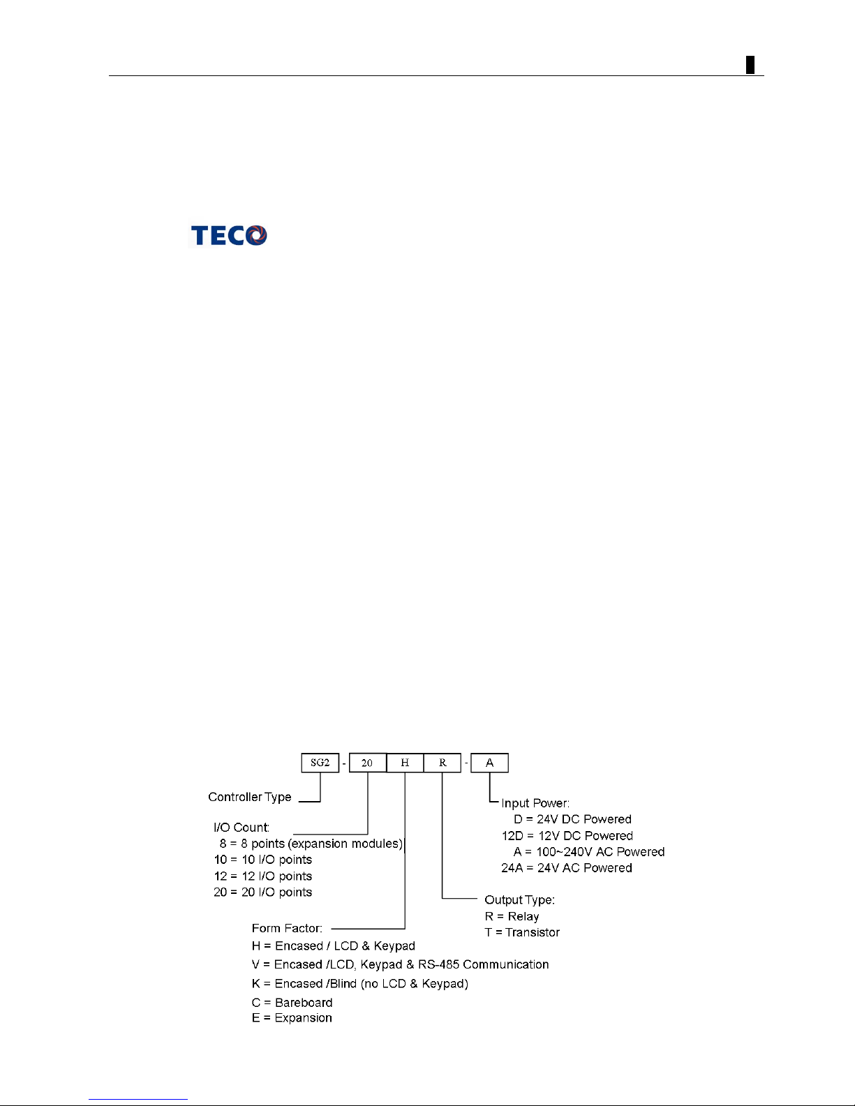
SG2 Model Identification
PDF compression, OCR, web optimization using a watermarked evaluation copy of CVISION PDFCompressor
Chapter 1: Getting Started 4
Quick Start Setup
This section is a simple guide for connecting, programming and operating your new SG2 smart relay. This is not
intended to be the complete instructions for programming and installation of your system. Refer to other sections in
the manual for more detailed information.
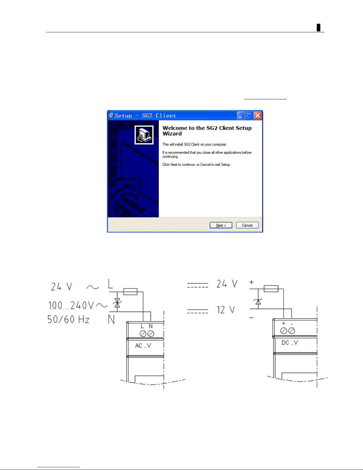
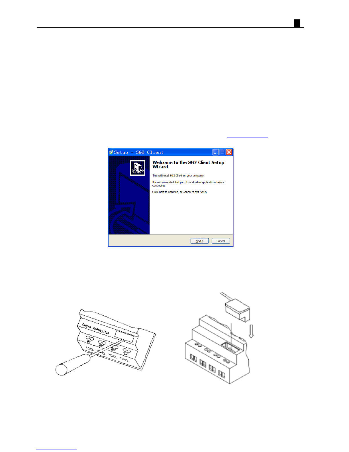
Install SG2 Client Software
Install the SG2 Client Software from CD or from the free internet download at www.teco.com.tw
Connect Power to SG2 smart relay
Connect power to the Smart Relay using the below wiring diagrams for AC or DC supply for the applicable
modules. See “Chapter 2: Installation” for complete wiring and installation instructions.
PDF compression, OCR, web optimization using a watermarked evaluation copy of CVISION PDFCompressor
Chapter 1: Getting Started 5
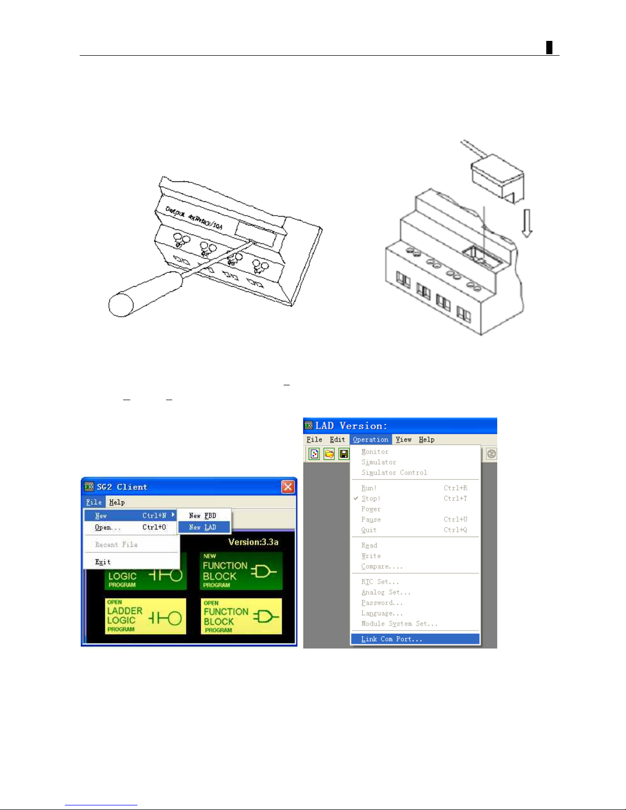
Connect Programming Cable
Remove the plastic connector cover from the SG2 using a flathead screwdriver as shown in the figure below.
Plug in the plastic connector end of the programming cable into the SG2 smart relay as shown in the figure below.
Connect the opposite end of the cable to an RS232 serial port or USB port on the computer.
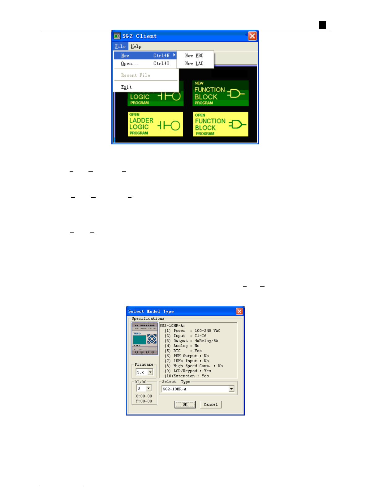
Establish Communication
a. Open the SG2 Client software and select “New L
AD” as shown below left.
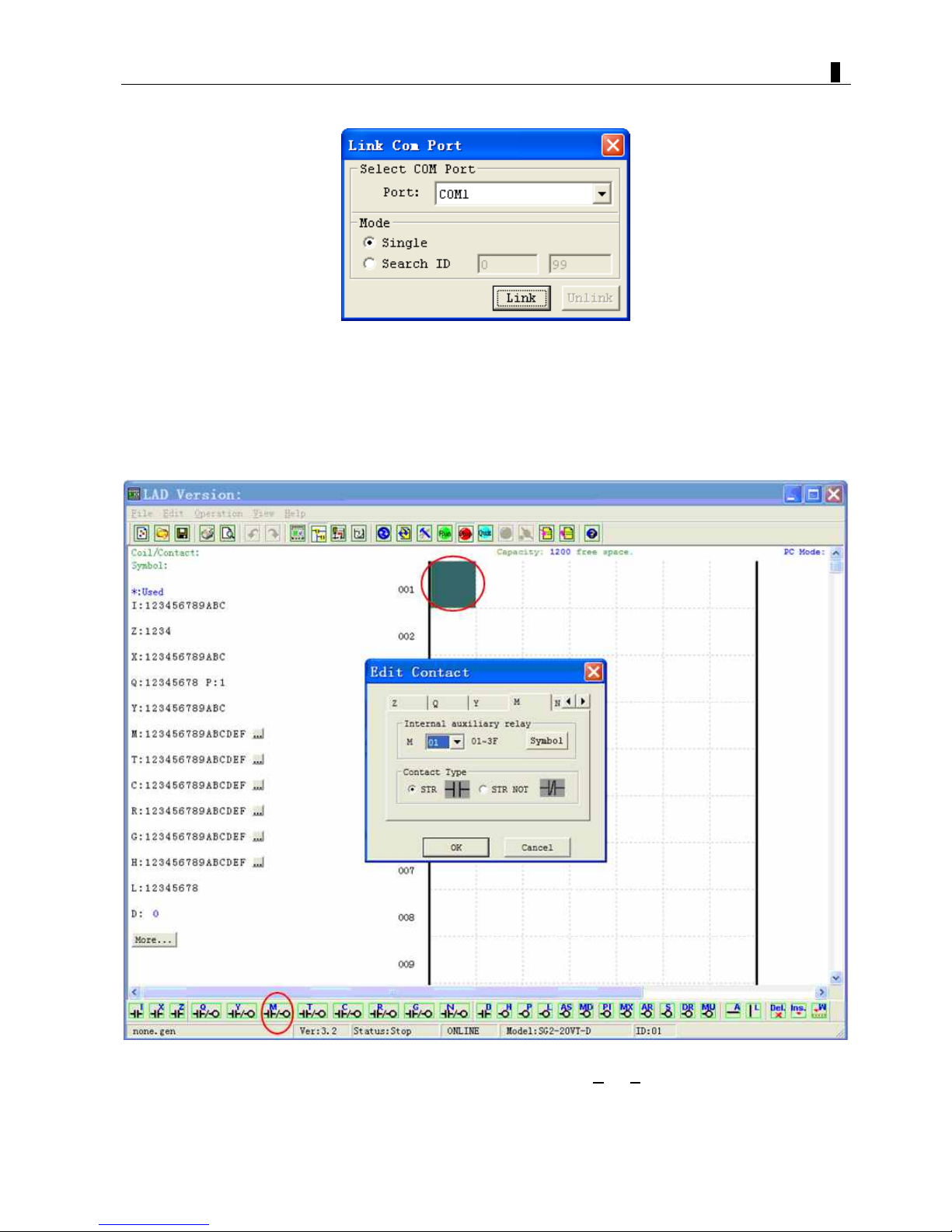
b. Select “Operation/Link Com Port…” as shown below right.
PDF compression, OCR, web optimization using a watermarked evaluation copy of CVISION PDFCompressor
Chapter 1: Getting Started 6
c. Select the correct Com Port number where the programming cable is connected to the computer then press the
“link” button.
d. The SG2 Client will then begin to detect the connected smart relay to complete its connection.
Write simple program
a. Write a simple one rung program by clicking on the leftmost cell at line 001 of the programming grid, then click
on the “M” contact icon on the ladder toolbar, as shown below. Select M01 and press the OK button.
See “Chapter 4: Ladder Programming instructions” for complete instruction set definitions.
Note: If the ladder toolbar is not visible at the bottom of the screen, select V
iew/Ladder Toolbar fr om the menu to
enable.
PDF compression, OCR, web optimization using a watermarked evaluation copy of CVISION PDFCompressor
Chapter 1: Getting Started 7
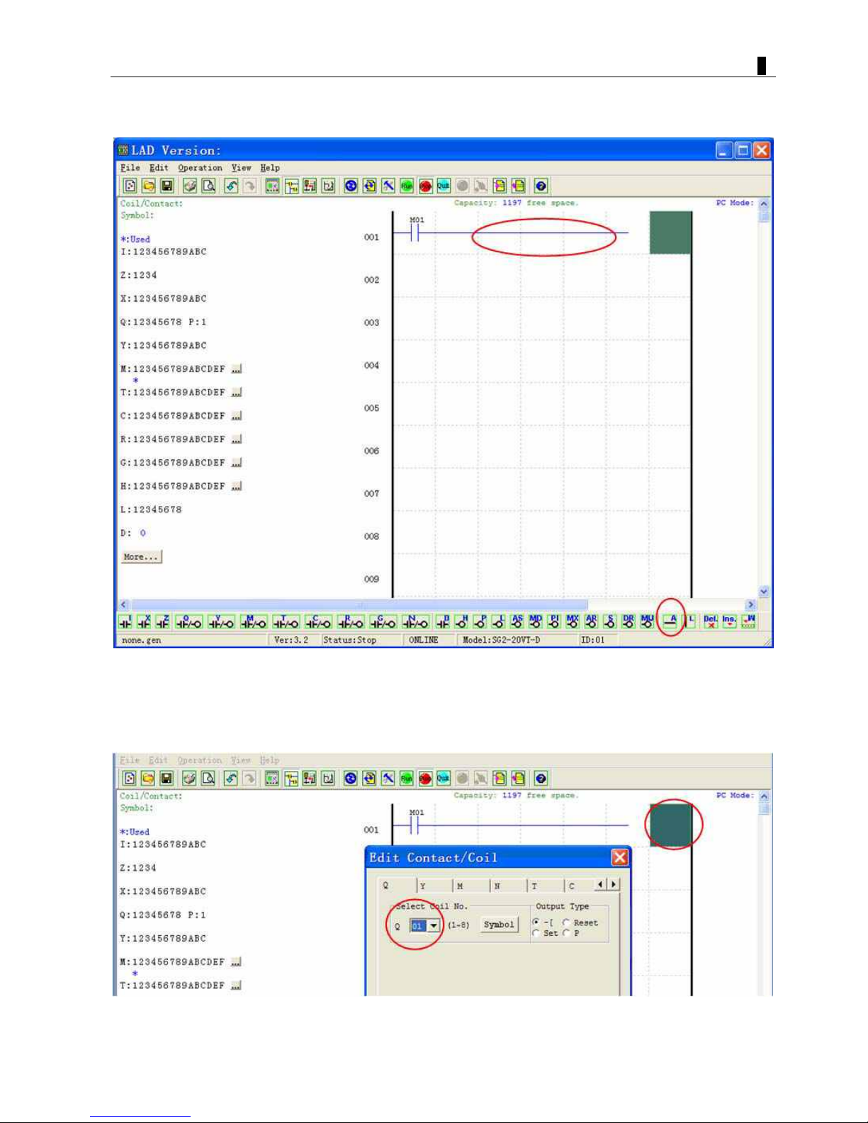
b. Use the “A” key on your keyboard (or the “A” icon on the ladder toolbar) to draw the horizontal circuit line from
the M contact to the right most cell, as shown below.
c. Select the “Q” coil icon from the ladder toolbar and drop it on the right most cells. Select Q01 from the dialog and
press OK as shown below. See “Chapter 4: Ladder Programming instructions” for complete instruction set
definitions.
PDF compression, OCR, web optimization using a watermarked evaluation copy of CVISION PDFCompressor
Chapter 1: Getting Started 8
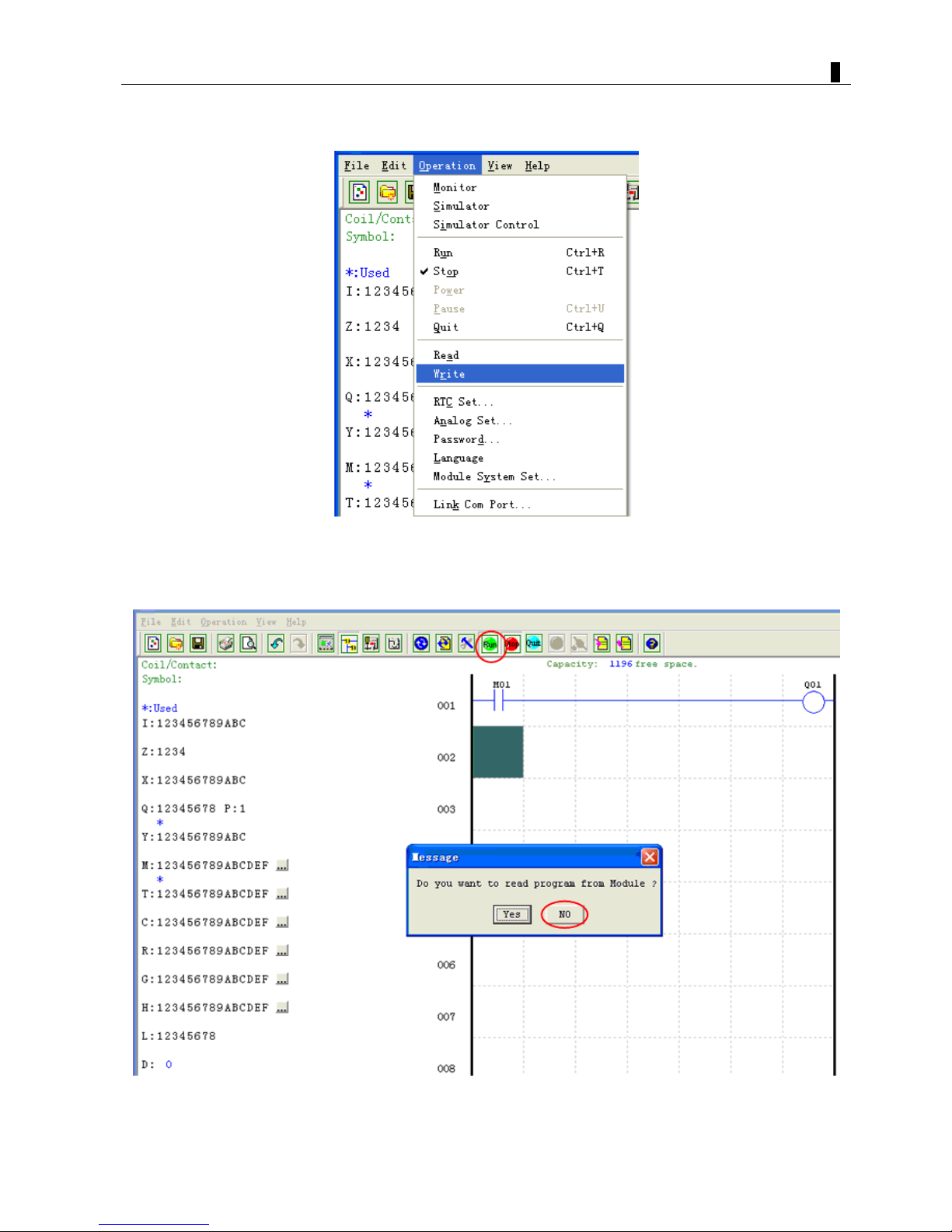
d. Test the simple program. From the Operation menu, select the Write function and write the program to the
connected smart relay as shown below.
e. Select the RUN icon from the toolbar, and select “No” when the pop-up message asks “Do you want to read
program from module?”, as shown below.
PDF compression, OCR, web optimization using a watermarked evaluation copy of CVISION PDFCompressor
Chapter 1: Getting Started 9
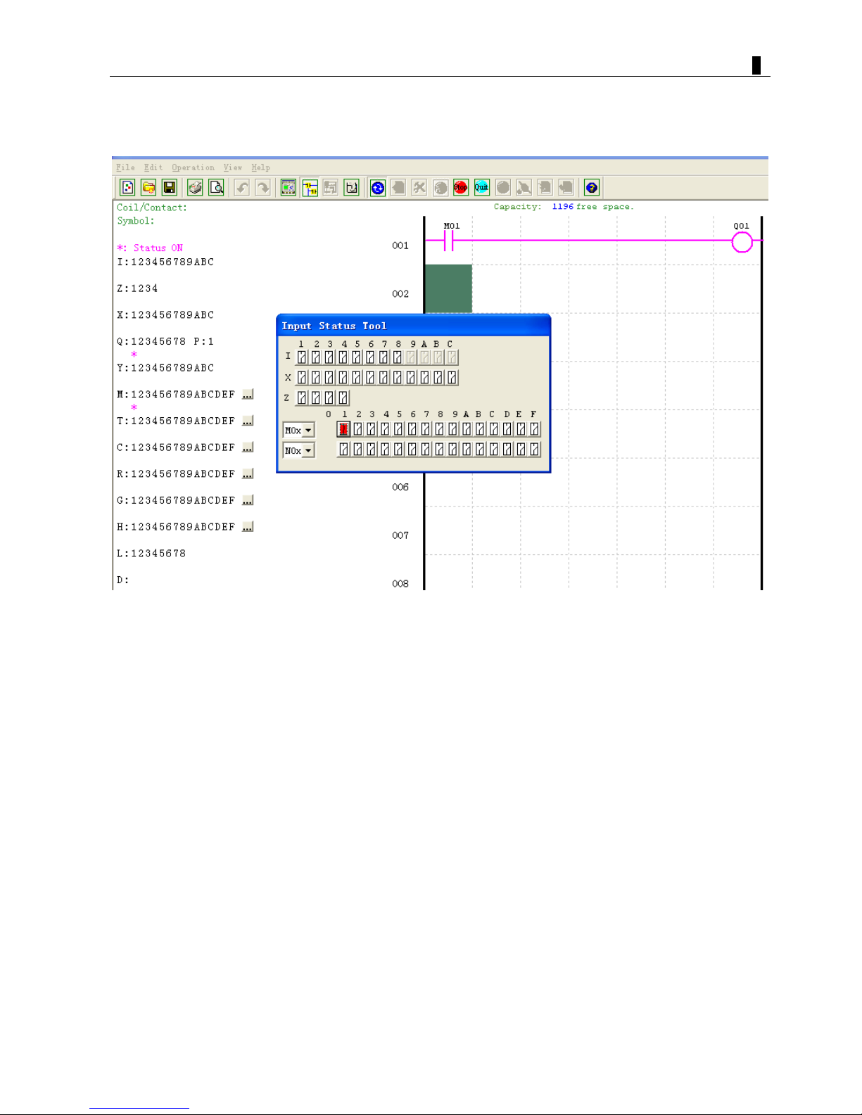
f. On the Input Status dialog, click on M01 to activate the contact M01 which will turn ON the Output Q01 as shown
below. The highlighted circuit shows the active part, and the first Output (Q01) on the connected smart relay will be
ON. See “Chapter 3: Programming Tools” for more detailed software information.
PDF compression, OCR, web optimization using a watermarked evaluation copy of CVISION PDFCompressor

Chapter 2 Installation 10
Chapter 2: Installation
General Specifications .......................................................................................................................................... 11
Product Specifications...........................................................................................................................................14
Mounting............................................................................................................................................................... 16
Wiring................................................................................................................................................................... 18
K type Indicator Light........................................................................................................................................... 20
PDF compression, OCR, web optimization using a watermarked evaluation copy of CVISION PDFCompressor

Chapter 2 Installation 11
General Specifications
SG2 is a miniature smart Relay with a maximum of 44 I/O points and can be programmed in Relay Ladder
Logic or FBD (Function Block Diagram) program. The SG2 can expand to its maximum I/O count by adding 3
groups of 4-input and 4-output modules.
Power Supply
Input Power Voltage Range
24V DC Models: 20.4-28.8V
12V DC Models: 10.4~14.4V
AC Models: 85-265V
24V AC Models: 20.4-28.8V
Power Consumption
24VDC: 12-point :125mA
20-point: 185mA
12VDC: 12-point: 195mA
20-point: 265mA
100-240VAC: 100mA
24VAC: 290mA
Wire Size (all terminals) 26 to 14 AWG
Programming
Programming languages Ladder/Function Block Diagram
Program Memory 300 Lines or 260 Function Blocks
Programming storage media Flash
Execution Speed 10ms/cycle
LCD Display 4 lines x 16 characters
Timers
Maximum Number Ladder: 31; FBD: 250
Timing ranges 0.01s–9999min
Counters
Maximum Number Ladder: 31; FBD: 250
Highest count 999999
Resolution 1
RTC (Real Time Clock)
Maximum Number Ladder: 31; FBD: 250
Resolution 1min
Time span available week, year, month, day, hour, min
Analog compare
Maximum Number Ladder: 31; FBD: 250
Compare versus other inputs
Numeric values or function block current value, such as
Analog input(A), Timer, Counter, Temperature Input (AT),
Analog Output (AQ), Analog*gain + Offset, AS, MD,
PI, MX, AR , DR …
PDF compression, OCR, web optimization using a watermarked evaluation copy of CVISION PDFCompressor

Chapter 2 Installation 12
Environmental
Enclosure T yp e IP20
Maximum Vibration 1G according to IEC60068-2-6
Operating Temperature Range -4° to 131°F (-20° to 55°C)
Storage Temperature Range -40° to 158°F (-40° to 70°C)
Maximum Humidity 90% (Relative, non-condensing)
Vibration 0.075mm amplitude, 1.0g acceleration
Weight
8-point:190g
10,12-point: 230g (C type: 160g)
20-point: 345g (C type: 250g)
Agency Approvals CUL, CE, UL
Digital Inputs
Current consumption
3.2mA @24VDC; 4mA @12VDC
1.3mA @100-240VAC
3.3mA @24VAC
Input Signal ”OFF” Threshold
24VDC: < 5VDC; 12VDC: < 2.5VDC
100-240VAC : < 40VAC
24VAC: <6VAC
Input Signal ”ON” Threshold
24VDC: > 15VDC 12VDC: > 7.5VDC
100-240VAC : > 79VAC
24VAC: >14VAC
Input On delay
24, 12VDC: 5ms
240VAC: 25ms 120VAC: 50ms
24VAC: 5ms
Input Off Delay
24, 12VDC: 3ms
240VAC: 90/85ms 50/60Hz
120VAC: 50/45ms 50/60Hz
24VAC: 3ms
Transistor device compatibility PNP, 3-wire device only
High Speed Input frequency 1kHz
Standard Input frequency < 40 Hz
Required protection Inverse voltage protection required
Analog Inputs
Resolution
Basic unit: 12 bit
Expansion unit: 12bit
Voltage Range acceptable
Basic unit: Analog input: 0-10VDC voltage,
24VDC when used as discrete input;
Expansion unit: Analog input: 0-10VDC voltage or
0-20mA current
Input Signal ”OFF” Threshold < 5VDC (as 24VDC discreet input)
Input Signal ”ON” Threshold > 9.8VDC (as 24VDC discreet input)
Isolation None
Short circuit protection Yes
T ot al number available
Basic unit: A0 1-A 04
Expansion unit: A05-A08
PDF compression, OCR, web optimization using a watermarked evaluation copy of CVISION PDFCompressor

Chapter 2 Installation 13
Relay Outputs
Contact material Ag Alloy
Current rating 8A
HP rating 1/3HP@120V 1/2HP@250V
Maximum Load
Resistive: 8A /point
Inductive: 4A /point
Maximum operating time 15ms (normal condition)
Life expectancy (rated load) 100k operations
Minimum load 16.7mA
Transistor Outputs
PWM max. output frequency 1.0kHz (0.5ms on,0.5ms off)
Standard max. output frequency 100Hz
Voltage specification 10-28.8VDC
Current capacity 1A
Maximum Load
Resistive: 0.5A/point
Inductive: 0.3A/point
Minimum Load 0.2mA
PDF compression, OCR, web optimization using a watermarked evaluation copy of CVISION PDFCompressor

Chapter 2 Installation 14
Product Specifications
Part # Input Power Inputs Outputs Display & Keypad RS-485 Communications Max I/O
SG2-12HR-D 6 DC, 2 Analog 4 Relay
√, Z01-Z04
N
/A 36 + 4 *1
SG2-12HT-D 6 DC, 2 Analog 4 Trans.
√, Z01-Z04
N
/A 36 + 4 *1
SG2-20HR-D 8 DC, 4 Analog 8 Relay
√, Z01-Z04
N
/A 44 + 4 *1
SG2-20HT-D 8 DC, 4 Analog 8 Trans.
√, Z01-Z04
N
/A 44 + 4 *1
SG2-20VR-D 8 DC, 4 Analog 8 Relay
√, Z01-Z04
Built-in MODBUS 44 + 4 *1
SG2-20VT-D
24 VDC
8 DC, 4 Analog 8 Trans.
√, Z01-Z04
Built-in MODBUS 44 + 4 *1
SG2-12HR-12D 6 DC, 2 Analog 4 Relay
√, Z01-Z04
N
/A 36 + 4 *1
SG2-20HR-12D 8 DC, 4 Analog 8 Relay
√, Z01-Z04
N
/A 44 + 4 *1
SG2-20VR-12D
12 VDC
8 DC, 4 Analog 8 Relay
√, Z01-Z04
Built-in MODBUS 44 + 4 *1
SG2-10HR-A 6 AC 4 Relay
√, Z01-Z04
N
/A 34 + 4 *1
SG2-20HR-A
100-240 VAC
12 AC 8 Relay
√, Z01-Z04
N
/A 44 + 4 *1
SG2-12HR-24A 8 AC 4 Relay
√, Z01-Z04
N
/A 36 + 4 *1
SG2-20HR-24A
24VDC
12 AC 8 Relay
√, Z01-Z04
N
/A 44 + 4 *1
Expansion Modules and Accessories
SG2-8ER-D 4 DC 4 Relay N/A
N
/A
N
/A
SG2-8ET-D
24VDC
4 DC 4 Trans. N/A
N
/A
N
/A
SG2-8ER-A 100-240VAC 4 AC 4 Relay N/A
N
/A
N
/A
SG2-8ER-24A 24VAC 4 AC 4 Relay N/A
N
/A
N
/A
SG2-4AI 4 Analog
N
/A
N
/A
N
/A
N
/A
SG2-4PT 4 Analog
N
/A
N
/A
N
/A
N
/A
SG2-2AO
N
/A 2 AnalogN/A
N
/A
N
/A
SG2-MBUS Communications Module, RS-485 ModBus RTU slaver
SG2-DNET Communications Module, DeviceNet Group2 slaver
SG2-PBUS Communications Module, Profibus-DP slaver
EN01 Communications Module, TCP/IP
GSM
24 VDC
Communications Module, EGSM 900MHz, DCS1800MHz
SG2-PL01 SG2 Programming Cable, SG2 Programming software
SG2-PM05(3rd) SG2 Memory cartridge
OEM “Blind” Models, No Keypad, No Display
SG2-12KR-D 6 DC, 2 Analog 4 Relay X
N
/A 36
SG2-12KT-D 6 DC, 2 Analog 4 Trans. X N/A 36
SG2-20KR-D 8 DC, 4 Analog 8 Relay X
N
/A 44
SG2-20KT-D
24VDC
8 DC, 4 Analog 8 Trans. X
N
/A 44
SG2-12KR-12D 12VDC 6 DC, 2 Analog 4 Relay X
N
/A 36
SG2-10KR-A 6 AC 4 Relay X N/A 34
SG2-20KR-A
100-240VAC
12 AC 8 Relay X
N
/A 44
OEM “Baseboard” Models, No Keypad, No Display, No Expansion
SG2-12CR-D 6 DC, 2 Analog 4 Relay X
N
/A 12
SG2-12CT-D 6 DC, 2 Analog 4 Trans. X N/A 12
SG2-20CR-D 8 DC, 4 Analog 8 Relay X
N
/A 20
SG2-20CT-D
24VDC
8 DC, 4 Analog 8 Trans. X
N
/A 20
PDF compression, OCR, web optimization using a watermarked evaluation copy of CVISION PDFCompressor

Chapter 2 Installation 15
SG2-10CR-A 6 AC 4 Relay X N/A 10
SG2-20CR-A
100-240VAC
12 AC 8 Relay X
N
/A 20
※ If module with keypad and display, Max IO can be added keypad input Z01-Z04.
※ More information about Product Specifications to see “chapter 6: Hardware Specification”.
PDF compression, OCR, web optimization using a watermarked evaluation copy of CVISION PDFCompressor
Chapter 2 Installation 16
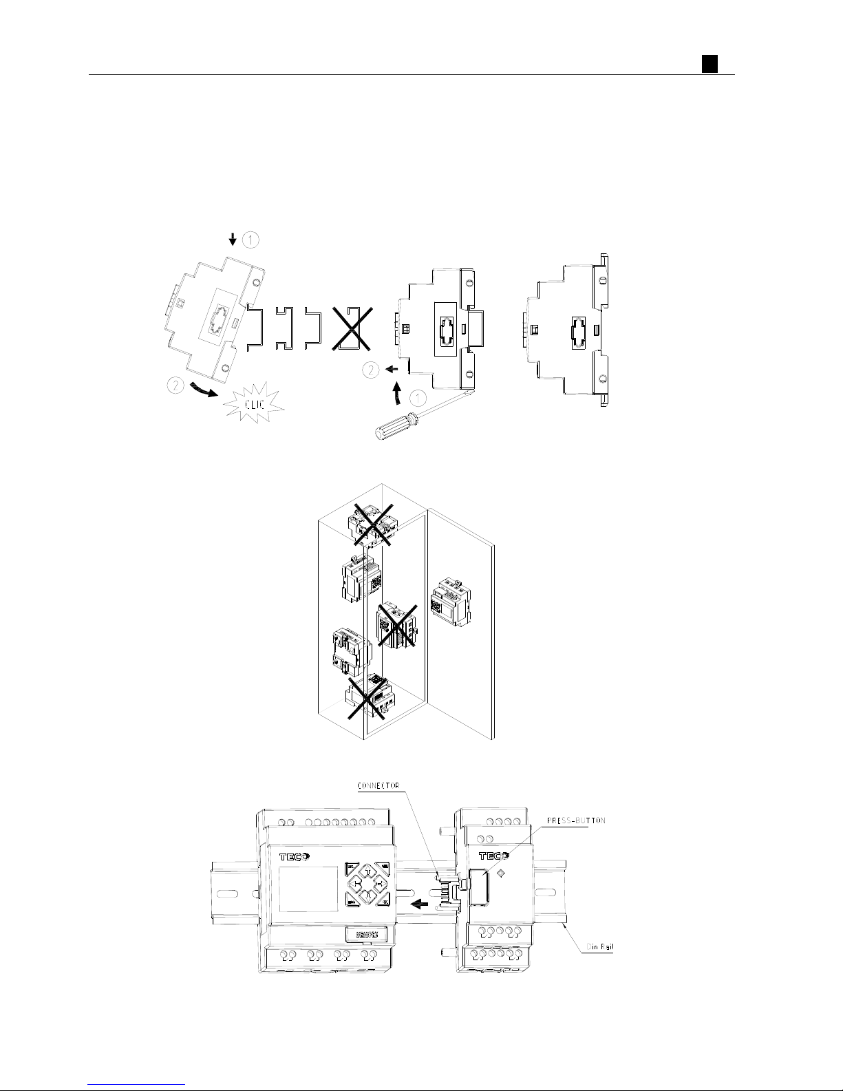
Mounting
DIN-rail Mounting
The SG2 smart relay should always be mounted vertically. Press the slots on the back of the SG2 and expansion
module plug CONNECTOR onto the rail until the plastic clamps hold the rails in place. Then connect the expansion
module and CONNECTOR with the Master (press the PRESS-BUTTON simultaneously)
SG2-8ER-A
Output 4 x Relay / 8A
Q1 Q2 Q3 Q4
DC 24V Input 8 x DC(A1,A2 0~10V)
SG2-12HR-D
+
-
I1 I2I4I3
I5
A1I6 A2
Input
4
× AC
L N
Run
AC 100~240V
X4X1 X2 X3
Output 4 x Relay / 8A
Y1 Y2
Y3 Y4
PDF compression, OCR, web optimization using a watermarked evaluation copy of CVISION PDFCompressor
Chapter 2 Installation 17
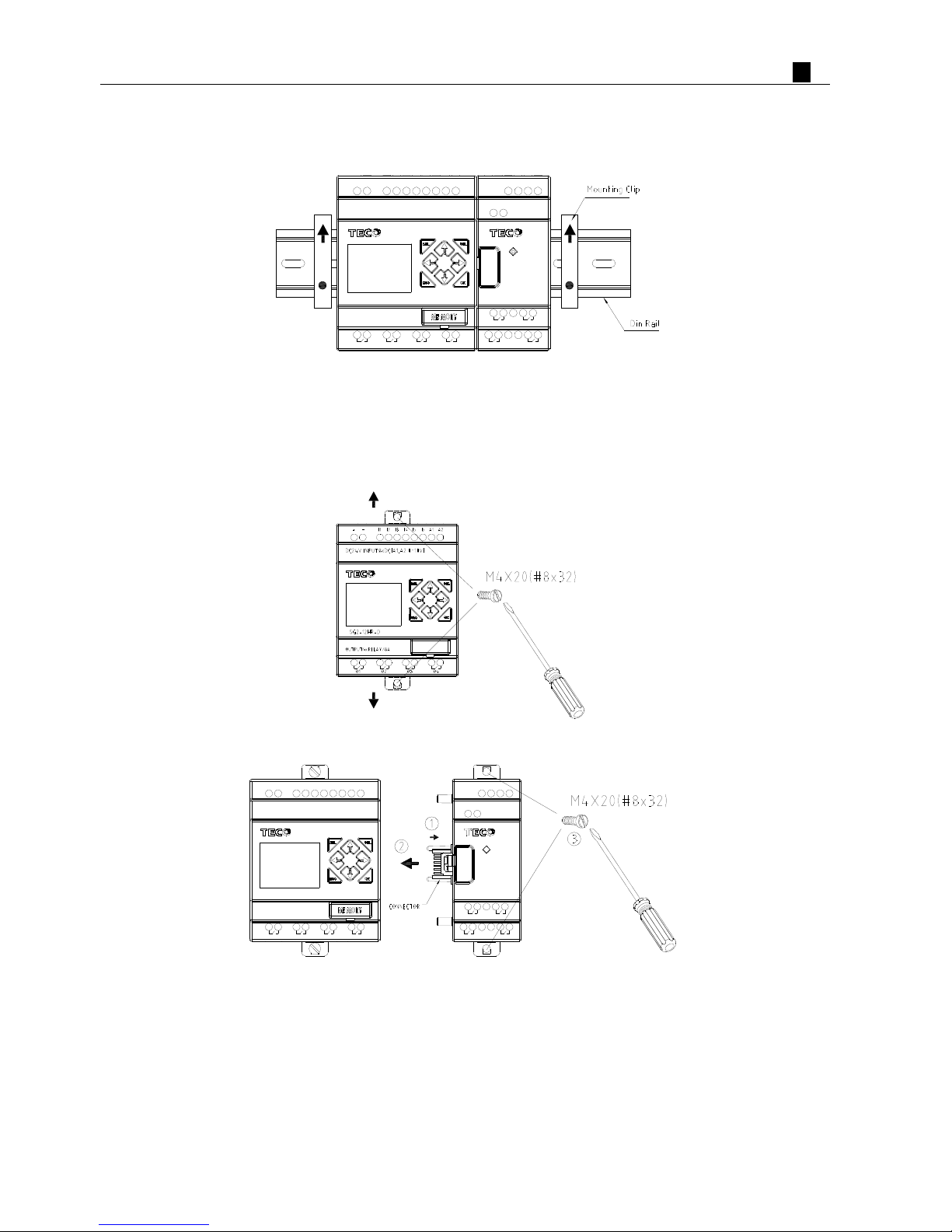
It is recommended to apply a DIN-rail end clamp to hold the SG2 in place.
Q3Q1
Output 4 x Relay / 8A
SG2-12HR-D
Q2
SG2-8ER-A
Q4
DC 24V Input 8 x DC(A1,A2 0~10V)
+
-
I1 I3I2 I4
Input
4
× AC
A2I6I5 A1
Run
AC 100~240V
N
L
X2X1 X3 X4
Output 4 x Relay / 8A
Y1 Y2
Y4Y3
Direct Mounting
Use M4 screws to direct mount the SG2 as shown. For direct installation of the expansion module, slide the
expansion module and connect with the Master after the Master is fixed.
Q2
Output 4 x Relay / 8A
SG2-12HR-D
Q1
Y1 Y2
Q3 Q4 Y3 Y4
SG2-8ER-A
Output 4 x Relay / 8A
Run
DC 24V Input 8 x DC(A1,A2 0~10V)
+
-
I1 A2I3I2 I4 I6I5 A1
Input
4
× AC
AC 100~240V
LN
X1
X3X2 X4
PDF compression, OCR, web optimization using a watermarked evaluation copy of CVISION PDFCompressor
Chapter 2 Installation 18
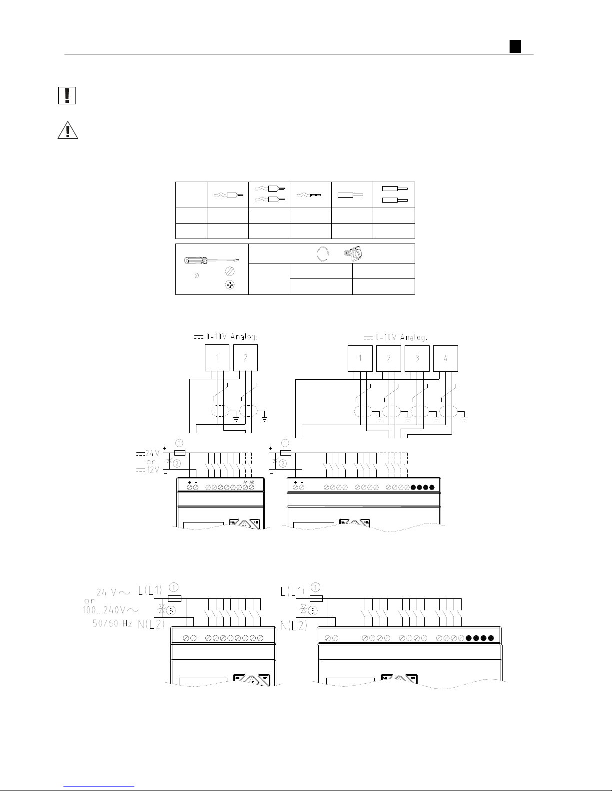
Wiring
WARNING: The I/O signal cables should not be routed parallel to the power cable, or in the same cable trays
to avoid the signal interference.
To avoid a short circuit on the load side, it is recommended to connect a fuse between each output terminals
and loads.
Wire size and Terminal Torque
Input 12/24V DC
Input 100~240V /24V AC
26...1626...1426...1426...1826...16
AWG
3.5
(0.14in)
lb-in
Nm
0.6
5.4
0.14...1.5
mm
2
0.14...1.50.14...2.50.14...0.75 0.14...2.5
C
C
10/12 POINTS 20 POINTS
+
-
A1 A2
-
+
A2
A1
A3
A4
12 POINTS 20 POINTS
A1 A3A2 A4
PDF compression, OCR, web optimization using a watermarked evaluation copy of CVISION PDFCompressor
Chapter 2 Installation 19
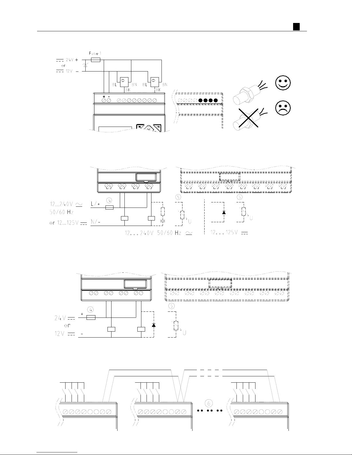
Sensor Connection
Output (Relay)
Output 4 x Relay / 8A
Q1 Q4Q3Q2
Output 8 x Relay / 8A
Q6Q2 Q3Q1 Q4 Q5 Q8Q7
Output (Transistor)
OUTPUT 8 x TR / 0.5A
Q1 Q2
Q4Q3Q1 Q2
OUTPUT 4 x TR / 0.5A
-
+
-
+
-
+
-
+
+
-
+
-
Q8Q7Q5 Q6Q3 Q4
+
--
++
-
++
--
+
-
IO Link OR Remote I/O Link
A2A3 A4A1 A2 A1
RS485
BA A3 A4
RS485
BA A3A1 A2 AB
RS485
A4
PDF compression, OCR, web optimization using a watermarked evaluation copy of CVISION PDFCompressor
Chapter 2 Installation 20
The power supply and the I/O supply should share the same power source. Only short circuit the first and the last
module.
When I/O link, the net can connect 8 products in max. (ID: 0-7).
When Remote I/O is available, it only can connect 2 products max (Master & Slaver).
※ More information about RS485 Model communication to see “Chapter 7 20 Points RS485 type Models
Instruction”.
①-1A quick-blowing fuse, circuit-breaker or circuit protector
②-Surge absorber (43V DC)
③-Surge absorber (Input 24VAC:43V; Input 100~240VAC:430V AC)
④-Fuse, circuit-breaker or circuit protector
⑤-Inductive load
⑥-Comply with standard: EIA RS-485.
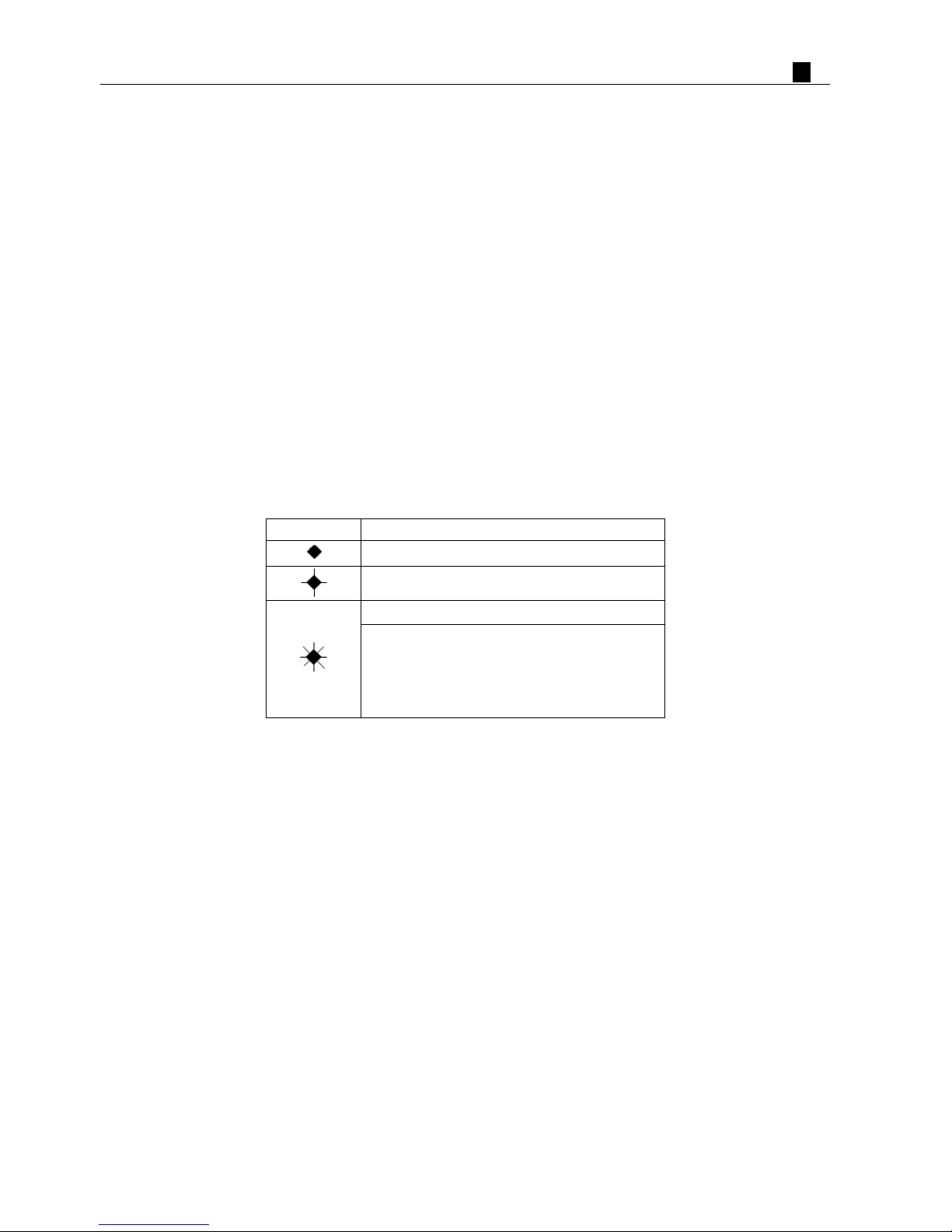
K type Indicator Light
There is an indicator light to indicate the status of SG2 (K type) smart, and the below table shows the
relationship between the light an d the SG2 status.
State of light Description
Power up, SG2 is stopping
Flicker slow(1Hz), SG2 is running
Flicker quick(5Hz), SG2 is under failure status
—Flash error
—Illogicality in user program
—Expansion model error
—RTC error
PDF compression, OCR, web optimization using a watermarked evaluation copy of CVISION PDFCompressor

Chapter 3 Program Tools 20
Chapter 3: Program Tools
PC Programming Software “SG2 Client”.........................................................................................................21
Installing the Software .................................................................................................................................. 21
Connecting the Software............................................................................................................................... 21
Start Screen ................................................................................................................................................... 21
Ladder Logic Programming Environment .................................................................................................... 22
Menus, Icons and Status Bar................................................................................................................. 23
Programming......................................................................................................................................... 24
Simulation Mode................................................................................................................................... 25
Establish Communication ..................................................................................................................... 25
Writing Program to smart relay............................................................................................................. 26
Online Monitoring/Editing.................................................................................................................... 27
Operation menu..................................................................................................................................... 28
HMI/TEXT............................................................................................................................................ 29
Program Documentation ....................................................................................................................... 33
Analog Output Set…............................................................................................................................. 35
3-Row/5-Row........................................................................................................................................ 36
Data Register Set…............................................................................................................................... 37
View menu ............................................................................................................................................ 39
FBD Programming Environment .................................................................................................................. 40
Menu, Icons and Status Bar................................................................................................................... 40
Programming......................................................................................................................................... 41
Simulation Mode................................................................................................................................... 42
Online Monitoring/Editing.................................................................................................................... 42
Symbol and Parameters list................................................................................................................... 43
Memory Cartridge (sold separately)................................................................................................................. 45
LCD Display and Keypad................................................................................................................................... 46
Keypad .......................................................................................................................................................... 46
Original Screen ............................................................................................................................................. 47
LCD Display Main Menu.............................................................................................................................. 50
RTC Daylight saving setting....................................................................................................................... 55
SG2 system error......................................................................................................................................... 59
PDF compression, OCR, web optimization using a watermarked evaluation copy of CVISION PDFCompressor
Chapter 3 Program Tools 21
PC Programming Software “SG2 Client”
T he SG2 Client programming software provides two edit modes, Ladder Logic and Function Block Diagram
(FBD). The SG2 Client software includes the following features:
1. Easy and convenient program creation and editing.
2. Programs can be saved on a computer for archiving and reuse. Programs can also be uploaded directly from a SG2
and saved or edited.
3. Enables users to print programs for reference and review.
4. The Simulation Mode allows users to run and test their program before it is loaded to the controller.
5. Real-time communication allows the user to monitor and force I/O on the SG2 smart relay operation during RUN
mode.
Installing the Software
Install the SG2 Client Software from CD or from the free internet download at www.teco.com.tw
Connecting the Software
Remove the plastic connector cover from SG2 using a flathead screwdriver as shown in the figure below. Insert
the plastic connector end of the programming cable into the SG2 smart relay as shown in the figure below. Connect
the opposite end of the cable to an RS232C serial port on the computer.
Star t Screen
Run the SG2 Client software and the below Start screen will be displayed. From this screen, you can perform the
following functions
PDF compression, OCR, web optimization using a watermarked evaluation copy of CVISION PDFCompressor
Chapter 3 Program Tools 22
New Ladder Program
Select F
ile -->New -->New LAD to enter the development environment for a new Ladder program
.
New FBD Program
Select F
ile -->New -->New FBD to enter the development environment for a new FBD (Function Block
Diagram) program.
Open Existing File
Select F
ile -->Open to choose the type of file to open (Ladder or FBD), and choose the desired program file,
and then click Open.
Ladder Logic Programming Environment
The Ladder Logic Programming Environment includes all the functions for programming and testing the SG2
using the Ladder Logic programming language. To begin a new program select F
ile-->New, and select the desired
model of SG2, and the number of connected expansion units if applicable, as shown below.
PDF compression, OCR, web optimization using a watermarked evaluation copy of CVISION PDFCompressor
 Loading...