

TECO seachill tr5, seachill tr10, seachill tr20, seachill tr30, seachill tr15 Operator's Manual
...Page 1

P
age 1
operators’
manual for all models:
TR5 TR10 TR15
TR20 TR30
TR60
Page 2
P
age
2
P
age 3
Purchased From
Date Purchased
Date Installed
Table of Contents
Safety ........................................................................... 4
Notes:
About This Manual
This manual covers basic operation and maintenance for all current models
of the Teco SeaChill under normal operating conditions. For more detailed
information or uses not covered in this manual please contact us.
Contact Us
United Kingdom distributor:
TradeMark Aquatics Ltd
Tel: 01509 26233 0
info@trademarkaquatics.co.uk
www.trademarkaquatics.co.uk
Model Number
Serial Number
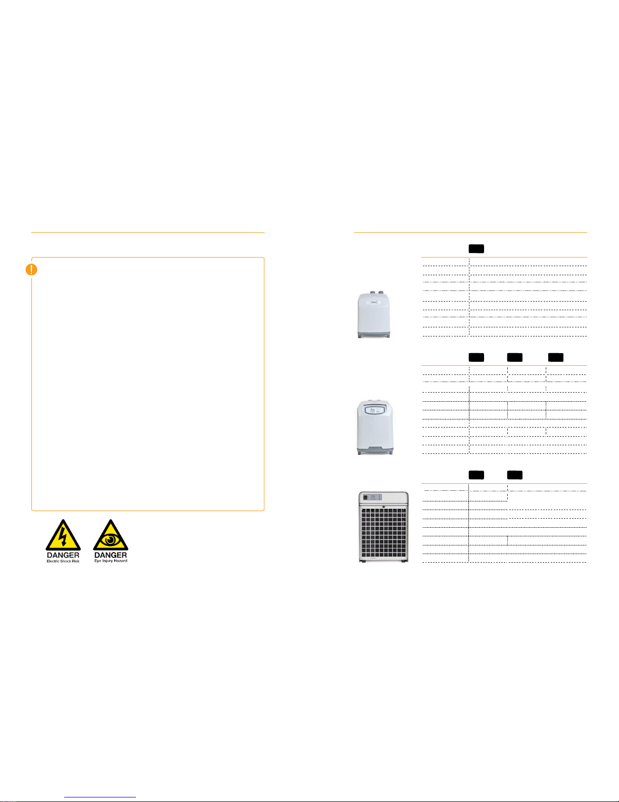
Specifications
. . .. . . . .. . . . . . . . . . . . . .. . . . . . .
5
F
eatures . . .. . . . .. . . . . . . . . . . . . .. . . . . . .
6-7 Rec
eiving and Inspection
. . .. . . . .. . . . . . . . . . . . . .. . . . . . .
8
Parts
List . . .. . . . .. . . . . . . . . . . . . .. . . . . . .
9-10
Installation and As
sembly
. . .. . . . .. . . . . . . . . . . . . .. . . . . . .
11-14
Oper
ation and Settings
. . .. . . . .. . . . . . . . . . . . . .. . . . . . .
15-17
Maint
enance
. . .. . . . .. . . . . . . . . . . . . .. . . . . . .
18-22
Troubleshooting
. . .. . . . .. . . . . . . . . . . . . .. . . . . . .
23
Page 3
P
age 4 P
age 5
Flow Rate
T
ank Siz
e
Dimensions
C
onnections
300
litres
180 - 600 gph
90 - 200 g 130 - 400 g
17" x 10 5/8" x 17 3/4"
5/8" or 3/4" Quick Disc
onnect
Teco chille rs are
desig ned and built with safety as a prim e consid er
ation ; indu stry-accepted
safety f
actors have been used in the desig n. Each chille r
is
inspec ted at
the f
act
ory f
or
safety and operation. Any necessary adjustments are made before shipment. Follow
the main tenance
sched ules outli ned in this manua l for
optim um perfo rmance
and safe
operation. Any repairs should be done only by qualified perso
nnel with proper training and
t
ools.
Car
efull y r
ead
all
safety r
equir ements before inst allation , opera tion or main tenanc
e.
The requirements are essential to ensure safe operation. Failure to follow these guidelines
v
oids the warranty and may r
esult in chill er damage or
persona l injur y.
•
Do
not install or try to r
epair a chiller that has been damaged in shipment.
See Receiving
And
Inspection for instructions.
• Turn off and unplug the chiller before pr
eforming any work. Electricity
has the pot
ential to
cause personal injury or equipment damage.
•
Do
not operate
the chiller at temperatures above
the maximum ambient temperature (95˚F
/35˚C)
•
Always supply electrical power that complies with the v
oltage
shown on the data label.
below the electrical outlet - this prevents water from reaching the outlet in the ev
ent of a leak.
• It is
rec
ommended that this pr
oduct be used with an
RCD (residual current device)
outlet.
•
Do
not look directly at an illuminated UV
light. (if installed)
•
Do
not operate
chiller without water flo
wing thr
ough it.
• Never
allow
heater to be on without water flo
wing though the chiller.
•
Do
not run pressurized
water thr
ough chiller. Chillers are designed to accept water flow from
recir
culating pumps. Pressure
pumps or high-pressure
water lines
will
damage
the chiller. If
in
doubt about your pump, c
ontact the pump manufacturer.
Safety
Specifications
Watts
200 230
420
•
Work on the refrigeration system must be done only by a licensed refrigeration technician.
Volts/Hz
110/60
•
Do not plug into wall socket without the housing in place.
dB / dB
(silent Mode)
39 / 37 40 / 38
41/ 39
•
Configure the electrical cord to include a “drip loop” - a loop section of chord that hangs
Weight
15 kg 39.5
lb.
44 lb.
HP
Amps
1/2 1
7.2
8.6
W
atts
818
980
110/60
111 lb.
V
olts/Hz
110/60 W
eight
96 lb. Flow
Rate
270 -
810 gph T
ank Size
up to
750 gallons
up to
1300 g
allons Dimensions
24" x
15" x 22"
C
onnections
1"
TR60 TR30
HP
1/8
1/5 1/3
Amps 2.5 2.6 3.9
TR20 TR15 TR10
HP
1/12
Amps
1.9
W
atts 180
V
olts/Hz 110/60
W
eight
14 kg
Flow Rate
500 l/hr
T
ank Size up to 150 litres
Dimensions
12.5" x 9
.5" x 13.5"
C
onnections
16mm or 20ml
Quick Disc
onnect
TR5
Page 4
P
age 6 P
age
7
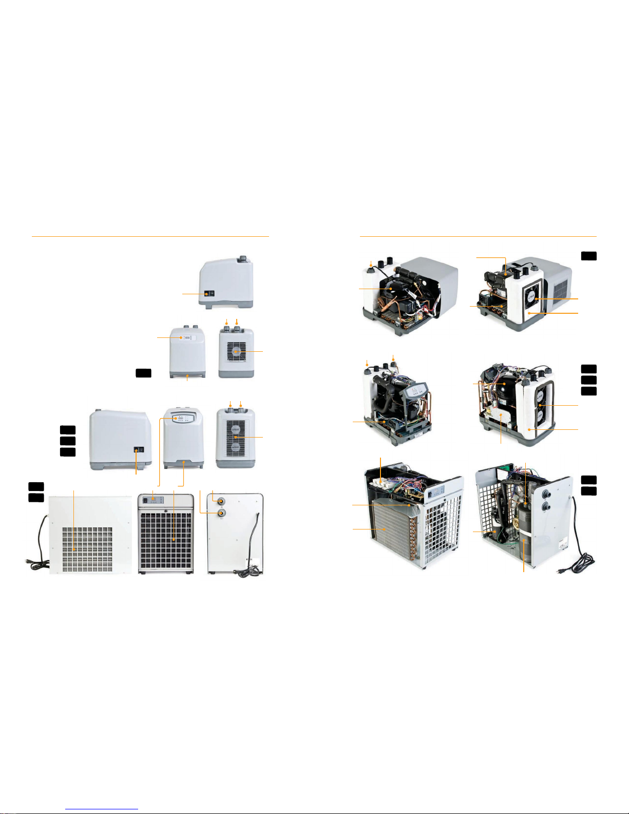
H
B
Features
J
A
Ventilation Grate
B
Air Filter
C
Control Panel
J
D
In Port
F
E
Out Port
L
F
Power Socket
D E
G
UV Port(s)
(Optional Accessory)
H
Heater Port(s) (Optional Accessory)
C
I
UV Ballast(s)
J
Compressor
A
H
G
K
Heat Exchanger
L
Condenser
M
Vent
Fan(s)
J
M
K
TR10
TR15
D E
TR20
M
L
A
K
TR30
A
F
C
B E D
I
I
H/G
TR30
TR60
TR60
M
L
J
K
TR5
TR5
TR10
TR15
TR20
Page 5
P
age 8 P
age 9
W
asher
TR10 TR15 TR20
TR5
TR30 TR60
Receiving and Inspection
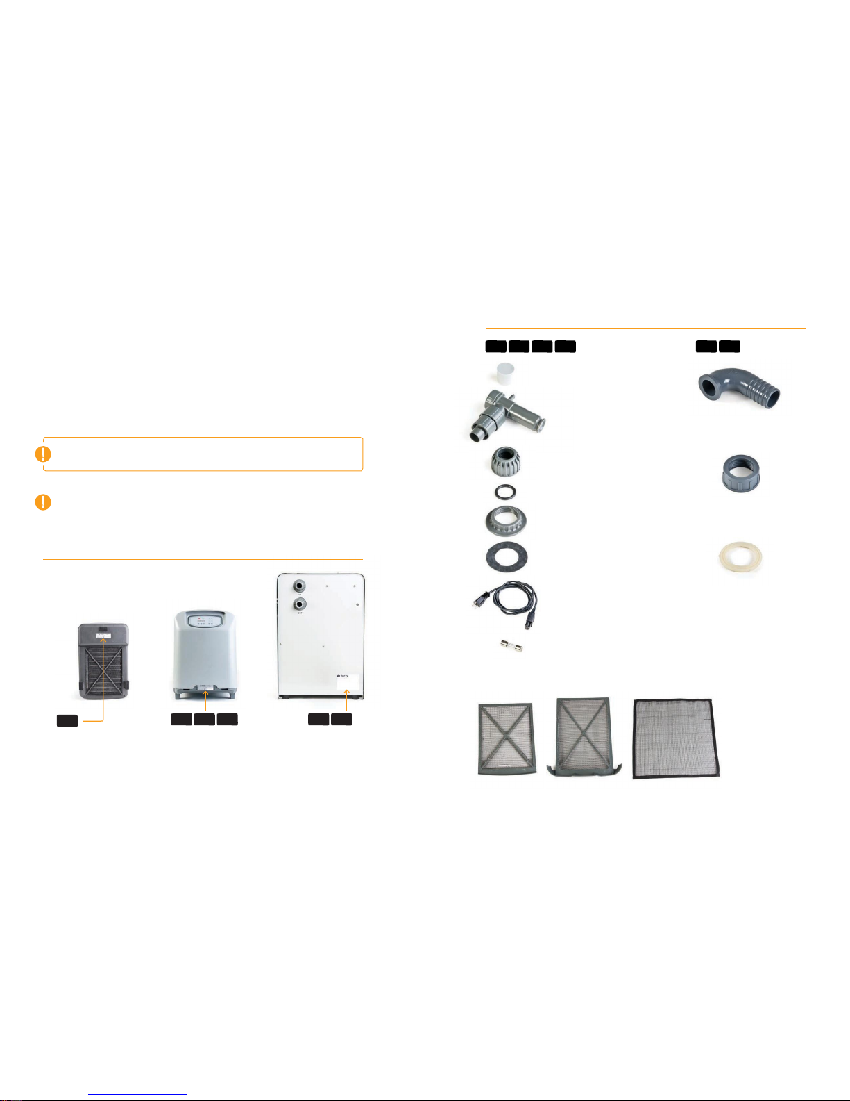
Included Parts List
1
Inspe ct the chiller clo sely upon rec eipt.
Record any indicatio n of damage and contact seller immediately.
2
Save the box and packing mater ials
If your chiller ever needs to be repaired or servic ed, you will need to ship it in the original box.
3
Record your Model and Serial Number for easy referen ce
There is a space on the first page of this manual to record this informat ion. You may be asked
for the serial number when calling for support .
In / Out Plugs
Located in the in/out ports of the
chiller (2) Attached to chiller
Shutoff Valve
(2)
Elbow
chiller (2) Attached to chiller
Ring Nut
Attached to chiller (2)
WARNING:
When the chillers are inverted during maintenance or shipping, you must let the unit
sit for at least 30 minutes upright to allow the coolant to settle: failure to do this before
O Ring
Attached to chiller (2)
Ring Nut
turning on the chiller may result in damage to the compressor.
Serial and Model Number Location
Housing Ring Nut
Attached to chiller (2)
Housing Gasket
Attached to chiller (2)
Located in the in/out ports of the
chiller (2) Attached to chiller
Located in the in/out ports of the
chiller (2) Attached to chiller
Power Cord
TR30/60 - Power Cord is attached to chiller
Fuse
1 installed, 1 spare
Air Filters
1 installed, washable / reusable
Bottom
Front , Underneath the Air Filter
Air filter must be removed to
access the serial and model number
Back
Note: Color and appearance of actual parts may vary slightly
TR30 TR60
TR5 TR10 TR15 TR20
NO
TE:
Our Quality Control
proc
edure
includes running water thr
ough the chiller to test the
c
ooling capacity. There
may be r
esidual water in the unit due to this method of testing,
this
is
normal.
Page 6

P
age 10 P
age 11
Optional Parts
Installation and Assembly
Flow Indi cator
400 W Heater Kit - TR5 Only
15 W UV Sterilizer Kit
Teco SeaChill Chillers are intended for indoor operation. Do not expose chiller to outside elements or direct
sources of heat. Maximum allowed ambient temperature is 95°F/35°C. Do not operate chiller in temperatures
over 95°F/35°C.
If the chiller is placed in an enclosed space (a cabinet or aquarium stand) it must have an air inlet as well as
a ventilation outlet. The air inlet should be at least the same size and dimensions as the air outlet and can be
placed to face the sides or front of the chiller.
Chiller must have a space of at least 8 in/20 cm between the ventilation grate and the wall for proper ventilation
to take place. If the chiller is inside of an enclosed aquarium stand the chiller will need to be 8 in/20cm from the
walls of the stand. If ventilation grate or fans must be placed closer than 8 in/20 cm to the wall, it is necessary
to create a ventilation outlet the same size and shape as the chiller ventilation grate or fans in the wall.
Required Parts and Tools (not Included)
Flexible Tubing
Pump with the recommended flow rate (see flow-rate specs on page 5)
Teflon Plumbers Tape (for PVC plumbing) or pipe thread sealant with Teflon
Tools you may need:
(for maintenance) Tongue & Groove Pliers, flat-head screwdriver, Phillips-head screwdriver, pliers
15 W Replacement UV Lamp
400 W Heater
Kit
ALL MODELS
W
ARNING:
The SeaChill w
ill produce excessive heat and not work properly if not placed in a
well ventilated area. C
ompressor
damage may occour.
W
ARNING:
Before cutting a v
entilation hole or grate in an aquarium stand, contact the stand
manufacturer to insure
that you
will
not compromise the structural int
egrity of the stand.
Page 7

P
age 12 P
age 13
Valve Assembly
Plumbing
1
Unscrew the Ring Nuts for the
shut off valves from the chiller
inlet and outlet. Remove the In/
Out plugs from the In/Out ports
of the chiller. Remove the O-rings
SeaChill Chillers can be plumbed using flexible plastic tubing or hard
plumbed using PVC.
Flexible Tubing
Above photos are of a TR5 model
from In/Out plugs. (do not discard
In/Out plugs– store for use should
you ever need to transport or ship
the chiller to another location).
2
Slide the Ring Nuts onto the Shut
Off Valves past the two small clips
of plastic projecting from the side
of the Shut Off Valves.
Note: Once Ring Nut s have been
pushed past the plastic clips on the Sh ut
Off Valves, do not rem ove Ring Nut
from Shu t Off Valves, this will break the
plastic clips, causing the valve to leak.
3
Roll the O Rings onto the Shut
Off Valve below the Ring Nut.
Do not push O Ring past plastic
clips on Shut Off Valves.
4
Place the Shut Off Valve into
the Outlet of the chiller, do not
use much force. Hand tighten
the Ring Nuts to seat the O-Ring
and attach the Shut Off Valve
Securely to the chiller.
Note: the first nipple on the Shut O ff
Valves will take 5/8” id tu bing. The
seco nd, l arger nip ple will accept 3/4” id
tubin g. R emove comp resss ion fittin g fo r
5/8” tubin g befo re us ing 3/4” tubing.
Use t he tubing size you prefer.
1
PVC
1
2
3
4
Attach flexible plastic tubing from the pump to the chiller
by sliding tubing over nipple on Shut Off Valves. Tighten
Compression Fitting over the end of the flexible plastic tubing
by turning fitting counter-clockwise until tubing is secure.
Note: If the chiller should ever need maintenance, it will be necessary to remove the
chiller cover. Do not hard plumb PVC to the chiller. Plan ahead and use ball valves or
gate valves to allow water flow to be shut off. Install unions to allow for the removal
of the chiller cover.
Recommende d PVC part s
(may be either schedule 40 or schedule 80 PVC)
For installation using PVC solvent socket type fittings:
•
1” FPT x Slip adapters (2)
•
1” PVC pipe, 1” Slip x Slip Ball Valves (2)
•
1” Slip X Slip Unions (2)
•
Teflon tape or pipe thread sealant with Teflon
Unscrew the Ring Nuts for the shut off valves from the chiller inlet
and outlet. Remove the In/Out Plugs from the In/Out ports of
the chiller (do not discard In/Out plugs – store for use should you
ever need to transport or ship the chiller to another location).
Keep the Housing Ring Nuts in place, wrap the male threaded
inlet and outlet from the chiller in Teflon tape or pipe thread
sealant with teflon to prevent leaks. Wrap Teflon tape at least
twice around threads. Check carefully for leaks. Slow leaks
may occur.
Screw the 1” FPT x Slip adapters over inlet and outlet to chiller.
Tighten firmly but do not use excessive force.
Assemble the remaining PVC as you wish making sure you can
easily unscrew the 1” FPT x Slip adapters to maintenance the
chiller if necessary.
ALL MODELS
W
ARNING: Do Not
Ov
ertighten T
hreaded
C
omponents to
Chiller:
T
ighten
firmly but do not use
excessive force.
Use t
ools and
mat
erials appr
opriate for use
with plastic components.
TR5 TR10 TR15 TR20
W
ARNING:
Do Not Ov
ertighten The
Shutoff Valves or Ring Nuts
The
shut-off v
alves should be able to r
otate
easily after tight
ening; overtight
ening may
cause water leaks or
permanently damage
your chiller.
Page 8

P
age 14 P
age 15
Typical Installations
Submersible Pump Installation
Closed Loop
Water is being run through the chiller
Operating Your Chiller
Starting Your Chiller
by a separate pump and returned
back to the sump.
External Pump Installation
Inline
In this installation the chiller is
plumbed between the main return
pump and the tank. Be sure that
the flow rate is not too high in this
situation. If it is, use a ball valve off of
the main line into the chiller to slow
the water flow.
1
Open the Shut Off Valves by rotating the valve
counterclockwise.
2
Turn on the pump from the aquarium to the chiller.
3
Check for leaks and adjust as needed.
4
Make sure water is circulating through the chiller at an
appropriate rate. (see chart)
5
Plug the chiller Power Supply Cable into the chiller and the
other end into an appropriate compatible source of electricity.
6
Turn power switch on.
Relocation after Installation
Canister Filter
In this installation water travels
through the canister filter into the
chiller where it is returned into
the aquarium. With this type of
installation filter the aquarium water
before it passes through the chiller to
reduce build up in the chiller.
1
Rotate the Shut Off Valves to the closed position.
2
Loosen the ring nuts for shut off valves.
3
Remove shut off valves from chiller inlet and outlet.
4
You may then move the chiller to another location
Note: If you are mo ving the chiller a long dist ance, it may be ne cessary
to place t he in/out plugs in t he in/out ports o f the chiller . Be sure to put
o-rings on in/out pl ugs before you put th em in the in/o ut por ts.
Note: These setup diagrams are intended to provide general examples of common plumbing arrangements, this does not cover all possible situations.
Pump, tubing, plumbing accessories are not included.
TR5
TR10,
TR15,
TR20
TR30, TR60
150gph - 27
0gph
180gph -
600gph
27
0gph - 810gph
ALL MODELS
PUMP
PUMP
PUMP
ALL MODELS
Page 9

P
age 16 P
age 17
Setting & Controlling Your Chiller
Setting & Controlling Your Chiller
Control Panel
All Teco Seachill models share the
same control functionality. The
following directions apply to all models,
with exceptions for Silent Mode, UV
Sterilizer, and Heater for models that do
not have those functions.
Silent Mode
1
Press “SILEN T”
when the chiller is on. Silent mode slows the
ventilation fan, causing the chiller to become quieter. Press “SILENT”
again to turn silent mode off.
Note: We strongly suggest using the silent function sparingly because it
reduces the cooling capability of the chiller considerably.
UV Sterilizer
1
Press “UV” If the optional UV sterilizer is installed, pressing the
UV button will activate the sterilizer. The green led light on the UV will
illuminate to indicate the UV light is on.
Note: If the optional UV kit is not installed the light will flash on and off
UV Sterilizer is not availble on the TR5.
Switching from Fahrenheit to Centigrade
Setting Temperature
The unit has been factory set at 77˚F, to change this setting follow the
steps outlined below.
1
Turn on the chiller. The power switch is located on the side of
the chiller near the power cord, the TR30 and TR60’s switch is
located on the control panel. Once power has been turned on the
chiller will begin to operate after approximately five seconds. The
display will show the current temperature of the a quarium water
passing through the chiller.
2
Push “SET” The display will change from the current
temperature to the set temperature.
3
Push up or dow n arr ow to chang e temperatu re.
Using the up and down arrows, set the controller to the desired
water temperature. The temperature will be set automatically
five seconds after you release the button.
4
Once the chiller reaches the set temperature the unit will enter
stand-by mode; both the lights above the temperature display will
be off. When the temperature changes the chiller or heater will
cycle on as appropriate.
Note: Illumin ated gre en LED indi cates chil ler is ope rational, illumin ated red LED
indicat es heate r is opera tional. (For units with ins talled heater s).
1
Press and hold both up
and
down arrows simu ltaneously
for 10 seconds. The display will automatically change from degrees
Fahrenheit to degrees Centigrade. To change back, repeat process.
Changing Temperature Display
The chiller reads the temperature from the water passing
through it, a thermometer reading directly from the tank may
be reading a different temperature depending on your specific
setup. Use this function if you would like to match the chiller’s
thermometer to a separate thermometer.
1
Press and hold “SET” for 10 secon ds.
The display will show a value of 1 or 1.5 (do not change this setting)
2
Press “SET” again
The water temperature (not the set point) will be displayed.
3
Push up or down arrow to change temperatur e.
After five seconds, the setting is entered into memory and the display
will return to full brightness. The unit will now function normally with the
new calibrated temperature.
TR10 TR15 TR20
TR10 TR15 TR20 TR30 TR60
ALL MODELS
ALL MODELS
TR5 TR10
TR15
TR20
TR30 TR60
ALL MODELS
Page 10

P
age 18 P
age 19
Cleaning the Air Filter
Removing Housing
Remove the filter from the bottom of the chiller.
Use a screwdriver to turn the plastic bolt 90˚
clockwise. (so the slot is verti cal to the ground)
This unlocks the ventilation grate and allows
you to remove the air filter.
1
Turn off and unplug the chiller. 2 Remove shut off valves by
unscrewing ring nuts. Remove housing ring nuts and gaskets.
You may need to
use a wrench or pliers to loosen the ring nuts,we recommend placing a cloth over
the ring nut to prevent damage to the plastic. 3 Pull out the air filter.
Unscrew and remove screws on the b ottom.
Use a phillips head screwdriver. You
may have to move the chiller to the edge of a table to do this.
4
Remove the housing.
Housing will remain attached to chiller via electric cables. Grasp the
bottom of the chiller and the edge of the power socket, pull up and turn housing over and to the side. Do not
operate the chiller until housing is replaced.
It is essential to keep the air filter on the SeaChill clean. A clean air filter will e nsure the unit is running at
maximum efficiency. All units have a sensor that will alert you if the air filter is being blocked. If the digital
display reads “AL1” this means the a ir filter is dirty or obstructed, and should be cleaned immediately.
1
For prope r operation , clean the filte r onc e per month.
2
Use a vacuum clean er or rinse the filte r unde r a sink unt il filt er is clean.
Do not use soap or o ther
cleaning chemica ls. Do not allow chiller to run for extended period s of time without an air filter.
1
Turn off and unplug the chiller. 2 Remove shut off valves b y unscrewing ring n uts Remove
housing ring nuts and gaskets.
You may need to use a wrench or pliers to loosen the ring nuts, we recommend
placing a cloth over the ring nut to prevent damage to the plastic 3 Pull out the air filter. Remove the
housing. First pull up on the case at the bottom, then pull up by gripping the back and the front control panel
recess. Do not operate the chiller until housing is replaced.
1
Turn off and unplug the chiller. 2 Remove screws from housin g. Sli de ho using about 8" (20 cm
back. Unplug green ground wire from housi ng. Slide the housing off.
Keep the plastic washers t hat come
with the housing screws, these prevent chipping of the housing powder coat. 3 Slide Ho using
completel y off. Do not operate the chiller until housing is repla ced.
TR30 TR60
TR10 TR15 TR20
TR30 TR60
TR5 TR5 TR10 TR15 TR20
Page 11

P
age 20 P
age 21
Changing the Fuse
Changing UV Bulb
Fuse Clip
1
Turn off and unplug the chiller before changing the fuse.
2
Remove the fuse holder from socket using a flathead screwdriver.
3
Remove blown fuse from clip and discard.
Fuse Holder
It is time to replace the UV L amp
when the AL2 code flashe s on the
control panel
4
Push out t he spare fuse ( contained in the fuse holder) , place new fuse in the clip, replace fuse holder.
1
Turn off chille r and unplug the chiller, Remove the housi ng (see directions on p.19)
2
Unscre w the ring nut for the UV ste rilizer po rt.
Changing the Fuse
Spare Fuse
Note: Some wires were removed for these photos
TR10 TR15 TR20
TR5 TR10 TR15 TR20
TR30 TR60
Page 12

P
age 20 P
age 21
3
Remove rub ber stoppe r fro m the quartz sle eve
4
Unplu g the old UV la mp from the 4-pin soc ket., remove and disc ard lamp.
5
Slide new UV lam p into quar tz sle eve, plug into 4-p in socke t, ret urn rubber stopper into
sleeve
Do not touch the glass of the UV bulb with your bare hands .
6
Tighte n ring nut over qua rtz sleeve
7
Replac e housing and air filter. Replace ring nuts and valves.
8
Open shut off valve s, rest art pump and check for leaks. Turn UV on by pressing UV button.
9
Hold dow n UV butt on for 10 seconds to reset AL2 code.
1
Turn off chi ller and unpl ug the chiller, Remove the hous ing
(see directions on previous page)
2
Remove the blue plastic cover fr om fuse, remove old fuse from clips
WARNING:
Do not touch the glass of the UV b ulb with your bare hands.
Oils on your hands will dramatically decrease the lifespan of the UV lamp. Use a clean
3
Install new fuse, replace blue plastic cover, replace chiller housing .
cloth to
handle the lamp during installation.
Page 13

Changing UV Bulb
Troubleshooting
It is time to replace the UV L amp
when the AL2 code flash es on the
control panel
1
Turn off chiller and unplug the chiller, Remove the housing (see directions on p.18)
2
Unscre w the ring nut for the UV sterili zer port.
3
Remove rub ber stopp er from the qu artz sleeve
4
Unplu g the old UV lamp fro m the 4-pin sock et., remove and discard lam p.
5
Slide new UV lamp into qua rtz sleeve, pl ug into 4-pin socket, retu rn rubber stopper into sleeve
Do not touch the glass of the UV bulb with your bare hands .
6
Tighte n ring nut over quar tz sleeve
7
Replac e housin g and screws
8
Open sh ut off valves, res tart pump an d check for lea ks. Turn UV on by pre ssing UV button.
9
Hold do wn UV button for 10 seconds to reset AL2 code.
1
Press and hold “SET” for 10 seconds.
The display will show a value of 1 to 20 - this is the current set differential
Page 22
2
Use the arrow Keys to change the set dif ferential
The set differential reflects the number of degrees variance upward
from the set temperature you wish to allow. For example, if you have the
set temperature at 25° C, but do not want the chiller to turn on until it
reaches 27° C, set the differential value to 2. The default setting allows
a variance of 1° C from the set temperature before the chiller turns on.
This value is intended to protect the compressor from excessive wear.
Page 23
TR30 TR60
W
ARNING:
Do not t
ouch the glass of
the UV bulb with y
our bare hands.
Oils on your hands
will
dramatically decr
ease the
lif
espan of the UV lamp. Use a
clean
cloth to handle the lamp during installation.
Pr
oblem Cause Solution
Display
does not light up
No
Electricity
Check that the power supply cable
is c
orrectly
c
onnected to both the chiller and outlet. Check that
the power switch is
ON. Check that the fuse
is
intact.
Dirty
Air F
ilter
C
lean Air F
ilter as
described on page 18.
Ambient T
emperatur
e
is too
high
L
ower the ambient temperature to
below 95° F/35° C
Obstruct
ed
V
entilation
Grate
R
emove
the obstruction or
cr
eate a ventilation hole.
Broken Fan
C
ontact info@trademarkaquatics.co.uk
UV lamp
R
eplace
the UV lamp with an appr
opriate TECO
UV
r
eplac
ement, available at www.tecous.com
W
ater temperatur
e
pr
obe has been
damaged
C
ontact info@trademarkaquatics.co.uk
C
ompres
sor overload
pr
obe
is
damaged
Check air
filter, check that v
entilation fans are
running.
C
ontact info@trademarkaquatics.co.uk
T
emperature
displa
yed
is
not correct
W
ater
is
losing or
g
aining heat thr
ough
long and/or un-
insulated tubing
R
educe
length of tubing, insulate
the tubing.
Check for
obstructions in tubing
Check that the pump
is
working
W
ater may not be
cir
culating thr
ough chiller correctly
Chiller
does not come on
until aquarium temperatur
e
is several degrees higher
than set point
T
emperature
offset
is
incorrect
R
eset temp diff
erential - see instructions below
W
ater flow
thr
ough chiller
has slo
wed
Calcium Buildup
Disc
onnect chiller from
aquarium. Run a 50% solution
of vinegar and water thr
ough chiller for 24 hours t
o
dissolve
buildup. T
horoughly flush chiller with Ro/DI
before connecting to aquarium.
Page 14

P
age 24
 Loading...