

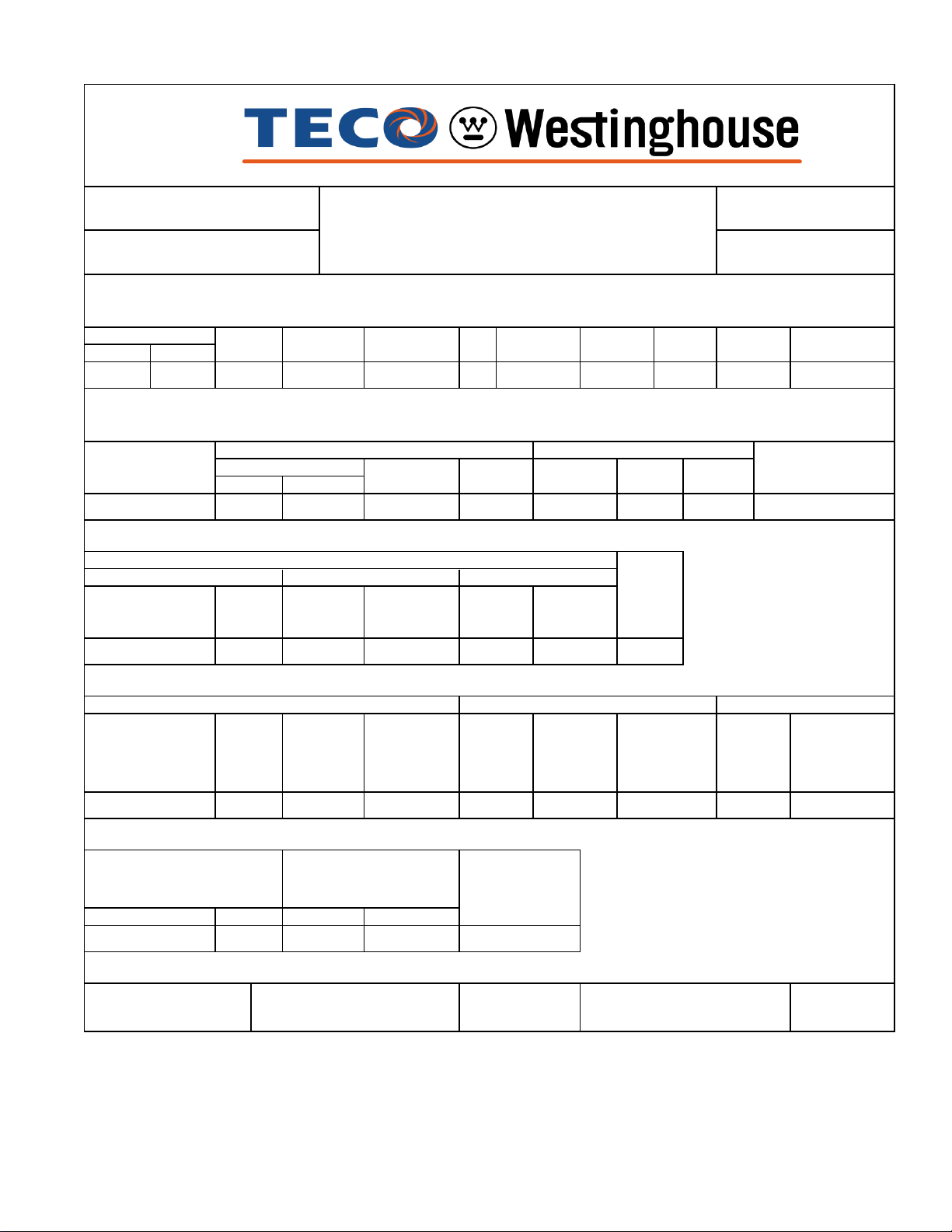
Teco PG4004 Reference Drawing

PG4004R
CURRENTS
TORQUE
POWER FACTOR
ACCEL TIME
ISSUED
EFFICIENCY
INERTIA
R
May 5, 2016
TYPE
AMHG
PERFORMANCE DATA
3-PHASE INDUCTION MOTOR
NAMEPLATE INFORMATION
OUTPUT
HP KW
400 298 60
POLE
4
FRAME
SIZE
5009C
VOLTAGE
2300/4000
TYPICAL PERFORMANCE
FULL
LOAD
RPM
1782
FULL LOAD
MIN. % NOM. %
94.5
3/4 LOAD
%
RATED
HZ
AMBIENT
1/2 LOAD
%
40oC
F. L.
%
84.095.0 94.5 93.4
INS.
CLASS
F
3/4
LOAD
81.1
NEMA
DESIGN
B
1/2 LOAD
ENCLOSURE
CATALOG#
TIME
RATING
CONT.
%
73.1
ODP
PG4004
SERVICE
FACTOR
1.15
MAXIMUM
POWER FACTOR
CORRECTION
KVAR115
NO LOAD FULL LOAD LOCKED ROTOR
AT
2300
VOLT
FULL LOAD
lb-ft
AT
4000
VOLT
LOCKED
ROTOR
%FLT
1179 115 110
SAFE STALL
TIME IN
SECONDS
COLD HOT
17 12
APPROVED:
AT
2300
VOLT
94.0
PULL
UP
%FLT
AT
4000
VOLT
54.3 364.0 G
BREAK
DOWN
%FLT
200
ALLOWABLE
STARTS
PER HOUR
COLD HOT
2 1
M. PRATER
AT
2300
VOLT
633.026.1 15.9
ROTOR
WR
lb-ft
113
SOUND
PRESSURE
LEVEL @ 3 FT
DRAWING NO.
2
2
dB(A)
86
NEMA
AT
4000
VOLT
NEMA
LOAD
WK
lb-ft
1553
2
2
KVA
CODE
LETTER
MAX
ALLOWABLE
WK
lb-ft
2
2
2330
31057PG4004
NEMA
LOAD
WK
Sec
2
MAX
ALLOWABLE
WK
Sec
5.27 7.73
REV.
2
0

ROTATION
DATE: CATALOG NO.:
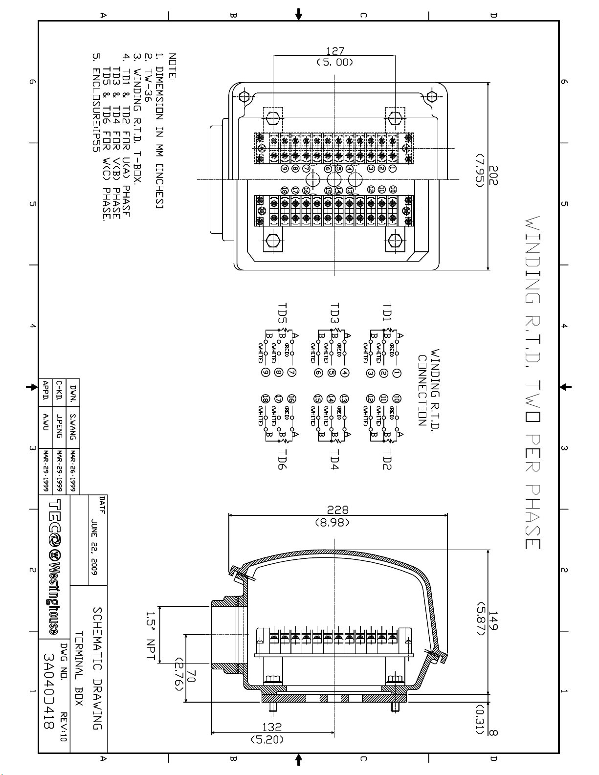
ONNECTION DIAGRAM
October 14, 2013
VOLTAGE CONNECTION
PG4004
SCHEMATIC DIAGRAM - 6 LEADS
(VIEWED FROM
2300
4000
DRIVE END)
DWG. NO.
3A061H475


OPERATION
&
MAINTENANCE
MANUAL
FOR
THREE PHASE
INDUCTION
MOTORS
56 thru 449T
Frame Motors

INDEX PAGE
1. INTRODUCTION ................................................................................................... 1
2. ACCEPTING, INSPECTION, STORAGE, TRANSPORTATION .............................. 2
3. INSTALLATION .................................................................................................... 4
3.1 Site and environment for motor installation ................................................... 4
3.2 Foundation ..................................................................................................... 4
3.3 Installation of shaft coupling .......................................................................... 6
3.4 Installation of belt drive .................................................................................. 9
3.5 Conveyance with chain or gear ...................................................................... 10
3.6 Electrical connections .................................................................................... 11
4. OPERATION ......................................................................................................... 12
4.1 Examination before starting ........................................................................... 12
4.2 Starting operation ........................................................................................... 15
5. MAINTENANCE .................................................................................................... 17
5.1 Major points in regular inspection and maintenance ...................................... 17
5.2 Motor windings ............................................................................................... 18
5.3 Cleaning of the interior of the motor ............................................................... 18
5.4 Cleaning of the exterior of the motor .............................................................. 19
5.5 Maintenance of anti-friction bearings ............................................................. 19
5.5.1 Frequency of re-lubrication .................................................................... 19
5.5.2 Kinds of grease ...................................................................................... 20
5.5.3 Grease quantity ...................................................................................... 20
5.5.4 Re-greasing ............................................................................................ 20
5.5.5 Oil re-lubrication ..................................................................................... 22
5.5.6 Cleaning and installation of bearings ..................................................... 23
5.6 Maintenance of sleeve bearings ..................................................................... 24
5.6.1 Daily inspection ..................................................................................... 24
5.6.2 Regular examination .............................................................................. 24
5.6.3 Disassembly .......................................................................................... 25
5.6.4 Re-assembly .......................................................................................... 26
5.7 Maintenance of slip rings (for Wound Rotor only) .......................................... 27
5.8 Maintenance of non-reverse ratchet mechanism (Vertical Motors only) 29
6. FAULT FINDING AND RECOGNITION .................................................................. 31
1. INTRODUCTION
This and the following instruction address the more common situations encountered in motor
installation, operation and maintenance. For the TWMC motor warranty to be and to remain in
effect, the motor must be installed and operated in strict accordance with the outline drawing,
motor nameplates and these instructions and must not be altered or modified in any unauthorized
manner.
During the installation and operation of motors in heavy industrial applications there is a danger of
live electrical parts and rotating parts. Therefore, to prevent injury and/or damage, the basic
planning work for installation, transportation, assembly, operation, etc. needs to be done and
checked by authorized and competent personnel only.
Since these instructions cannot cover every eventuality of installation, operation and
maintenance, the following points should be considered and checked.
• The technical data and information on permissible use such as assembly, connection,
ambient and operating conditions given in the related catalogue, operating instructions,
nameplates and other production documentation.
• The general erection and safety regulations.
• The local and plant-specific specifications and requirements.
• The proper use of transport, lifting devices and tools.
• The use of personal protective equipment.
Following indications should be observed when reading these instructions.
Safety instructions are marked as follows:
Warning of electric hazards for personnel.
Warning of dangers for personnel.
ATTENTION!
Warning of damage for the motor or installation.
1

2. ACCEPTING, INSPECTION, STORAGE, TRANSPORTATION
Inspection upon receipt
Check the following points upon receipt:
• Are the nameplate ratings identical with what you ordered?
• Are dimensions and color in compliance with your specifications?
• Are the nameplate ratings for space heater, thermal protector, temperature detector, etc.
identical with what you ordered?
• Is there any damage?
• Are all accessories and accompanying instruction manuals in good order?
• Please ensure that the arrow head indicator really indicates direction of rotation.
• If there are any specific requirements, please ensure they are in conformity with your
specifications.
• Motor stator housing may be outfitted with condensation drain holes that are
either open holes, drain holes with plugs or drain holes with breather drains. For
horizontally mounted motors position the drain holes at the lowest point possible
to allow for the egress of condensation. For vertical shaft installations the lower
end bracket must be outfitted with drains at the lowest point possible. Prior to
installation remove drain plugs if fitted.
2.1 Storage
When motors are not in operation, the following precautionary measures should be undertaken to
assure best performance.
2.2 Place
(a) High and dry, well ventilated without direct sun, dust or corrosive gas.
(b) Not located near to a boiler or freezer.
(c) Entirely free from vibration and easily accessible.
(d) Motors should be put on pallets to prevent moisture.
2.3 Moisture prevention
Since moisture can be very detrimental to electrical components, the motor temperature should be
maintained about 37ºF (3°C) above the dew point temperature by providing either external or
internal heat. If the motor is equipped with space heaters, they should be energized at the voltage
shown by the space heater nameplate attached to the motor. Incandescent light bulbs can be
placed within the motor to provide heat. However, if used, they must not be allowed to come in
contact with any parts of the motor because of the concentrated hot spot that could result.
2

2.4
ATTENTION!
Even during storage, the insulation resistance should be kept above the specified values.
(a) For measurement of insulation resistance and acceptable standard values, please refer to
measures stated in 4.1.2 “Measurement of insulation resistance”.
(b) Insulation resistance test should be performed once every three months.
2.5
If the motor is not in operation for a long period (one week and above) after installation or has
been in operation but stopped for a period of time, the following precautions must be taken.
(a) Protect the motor in accordance with measures stated in 2.3.
(b) Insulation resistance test should be performed as stated in 2.4.
2.6 Bearing protection
(a) If the motor has been provided with a shaft shipping brace to prevent shaft movement
during transit, it must be removed before operating the motor. It is very important that
this brace be re-installed exactly as it was originally, before the motor is moved from
storage or any time when the motor is being transported. This prevents axial rotor
movement that might damage the bearings.
(b) Motors equipped with sleeve bearings are shipped from the factory with the bearing oil
reservoirs drained. In storage, the oil reservoirs should be properly filled to the center of
the oil level gauge with a good grade of rust inhibiting oil. To keep the bearing journals
well oiled and to prevent rusting, the motor shaft should be rotated several revolutions
about every month ensuring the shaft does not come to rest in its original position. While
the shaft is rotating, it should be pushed to both extremes of the endplay.
(c) Motors with anti-friction bearings are properly lubricated with the correct grade of grease
at the factory and no further greasing is required in storage. The shaft should be rotated
several revolutions about every month to maintain proper distribution of the grease within
the bearings.
elapsed between manufacture and use, or while in storage for extended time. It is a
good practice to always replenish and purge with fresh grease at start up.
However, re-greasing is required if a significant period of time has
(d) Tilt-pad bearings are a type of sleeve bearing used in special design applications. Due to
the nature of this bearing, a loose oil ring for delivering lubricant cannot be provided.
Therefore, during the storage interval, oil must be periodically manually introduced into
the pads and housing to prevent the occurrence of oxidation of the precision machined
components.
(1) Remove the pipe plug from the bearing cap located above the tilt-bearing shell.
(2) Pour in approximately one cup of oil every month and rotate the shaft a few revolutions
about every two (2) weeks.
(3) For long periods of storage, the oil that accumulates in the housing should be removed.
Care should be taken to keep parts such as fitting surfaces, key, shaft extension and axial
central hole free from any foreign matter. Grease should also be generously applied to
prevent rusting.
3
2.7 Transportation
To keep the rotating parts of motors from moving, thus preventing damage and scratching during
transportation, they should be held securely with a locking device. Remove all transit clamps
before operating the motor. It is very important that this device be reinstalled exactly as it was
originally, before the motor is moved from storage or any time when the motor is being
transported. The vertical mounting type motors should be transported in the vertical position.
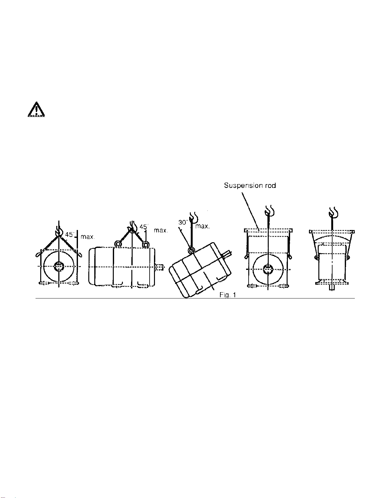
Do not use the hoisting hook/eyebolts to lift more that the motor itself. They are
designed to support the motor only. Make sure the hoisting hook is correctly
attached to the eyebolt(s)/lug(s) and they are fully screwed in before hoisting.
Also note such parts as fan cover, ventilation box, bracket, slip-ring, etc. may have
their own hoisting lugs which can only carry their own weight. Nothing extra
should be attached while hoisting.
Do not twist the steel wires and make sure the eyebolts have been firmly screwed
in and the sling angle is correct. See figure 1.
3 INSTALLATION
Site and environment for motor installation
3.1.1
Standard environment and site conditions for the installation of motors are usually set as follows:
(a) Ambient temperature: -14~104ºF (-10~40°C)
(b) Humidity: Relative humidity below 90%RH for totally enclosed types, and below 80%RH for
semi-enclosed types.
(c) Elevation: below 3,300 feet (1,000 meters).
(d) Harmful gases, liquids, dusts, high moisture should be absent.
(e) Foundations should be strong and free of vibration.
If there are any special environmental conditions, please inform TWMC prior to ordering.
3.1.2 Ventilation and space
(a) Installation area should be well ventilated.
(b) The installation space should be large enough to facilitate heat dissipation and
maintenance.
4
3.2 Foundation
3.2.1
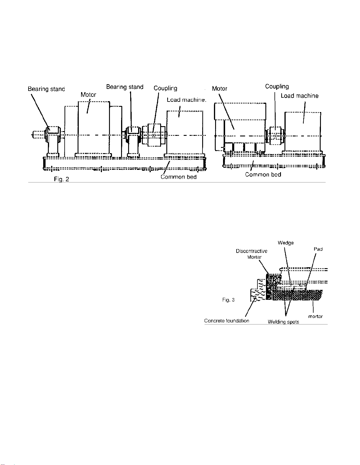
Use rigid and solid sole plate or common bed as foundation.
For best motor performance, it is advisable to use a sole plate or common bed, particularly when
using a shaft coupling. See figure 2.
3.2.2 Installation
(a) Select an appropriate foundation surface for the sole plate or common bed, which will be
considered the final level.
(b) Align the position of the common bed with
reference to that level.
(c) Align the level accuracy at a minimum of four
points such as bearing mounting, shaft
extension etc. The accuracy should be
within .0015 inches (0.04mm).
(d)Sole plate or common bed should be
embedded in concrete foundation as illustrated
in Fig. 3. Stiff pads should also be installed
beneath the wedges, which are welded together
at various spots about 15.75-19.70 inches
(400-500mm) apart etc., to enable the
foundation to carry evenly the weight of the whole motor.
(e) The base should be sturdy and rigid to keep it flat and level.
(f) Make sure the mortar and concrete are completely dry, and the precision of the level is
acceptable, and then set the motor on the mounting foundation.
(g) Accurately install shaft couplings, belt sheaves etc., then weld the wedges solid to prevent
untoward change in position.
3.2.3 The foundation of vertical induction motors: (Also the foundation of pump)
(a) Foundation of motor/pump must be rigid and secure to provide adequate support. There must
be no vibration, twisting, misalignment etc. due to inadequate foundations.
(b) A massive concrete foundation is preferred in order to minimize vibration. Rigidity and
5
 Loading...