

Page 1
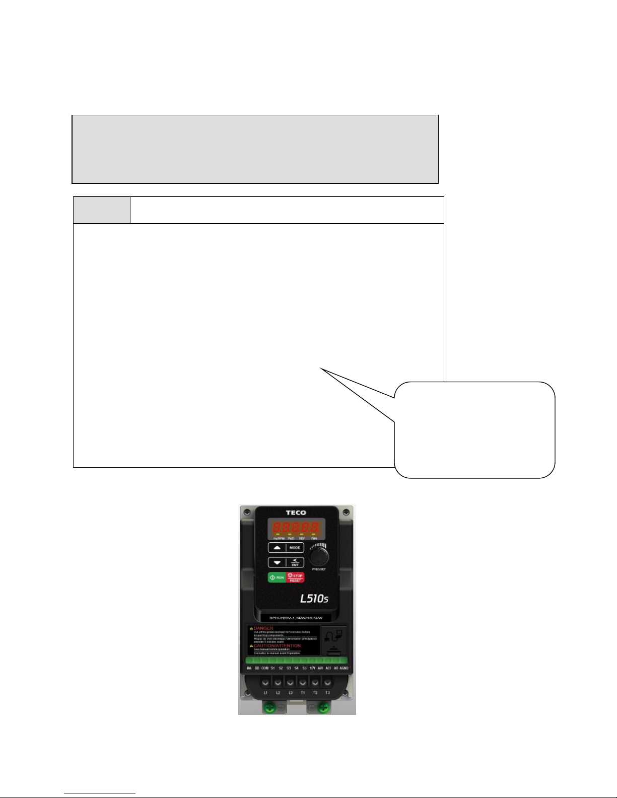
Page 1 of 9 06/10/17
TECO L510s Inverter
Quick Start Guide
1) Ensure that the Inverter & the motor have the correct
KW power and voltage ratings.
Motor full load amps must not exceed the Inverter rating.
2) Ensure that the supply & Motor cables are connected
correctly prior to power up.
3) For single phase supply, use L1(L) & L3(N) on units which
have 3 supply terminals.
4) Connect motor cable to terminals T1, T2 &T3.
(Swap two leads if motor runs in reverse direction).
5) Connect supply Earth and the motor Earth to the drive Earth
terminal.
Note:-
I ) For detailed installation
and wiring refer to the
Instruction manual.
This guide is to assist you in installing and running the inverter and verify that it is
functioning correctly for it’s main and basic features.
For detailed information and if there are any doubts please refer to the instruction manual.
Step 1
Supply & Motor connection
Page 2
Page 2 of 9 06/10/17
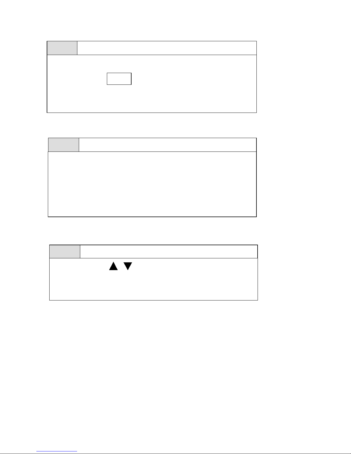
Apply power to the drive, the display will briefly show the supply voltage
220V followed by flashing.
This is the default (factory set) frequency.
If the unit has been used previously then it will show the last frequency
programmed.
Step 2
Apply power to the drive
5.00
Step 3
Test run from keypad
Press RUN KEY to run.
The frequency will ramp up to 5.0 Hz or the user pre-set frequency and
according to the default acceleration ramp time.
Press STOP key to stop.
The frequency will ramp down to zero according to the default decel ramp
time.
Step 4
To alter frequency from keypad. (Default setting).
Use the Arrow keys and
< /
ENT
To alter the digits to the required frequency.
eg. 50.0 HZ then use RUN and STOP keys to start / stop.
Page 3
Page 3 of 9 06/10/17
Remote speed reference and Remote run
1) Ensure that you have carried out installation & wiring requirements as per
previous page before you proceed.
2) For remote potentiometer OR remote 2-10V / 0-10V dc signal use the
following terminals:
Terminal 10V. The supply provided for use with the potentiometer.
Terminal AVI. Potentiometer wiper connection.
Terminal AGND. 0Vdc.
For 0-20mA / 4-20mA signals use the following terminals:
Terminal ACI.
Terminal AGND. 0Vdc.
Step 1
Remote mode wiring. Speed reference .
Step 2
Remote mode Run
1) Connect remote start switch if required according to diagram in the
instruction manual.
Terminals +24V & S1 (Forward run)
Terminals +24V & S2 (Reverse run)
Note: For Frames 3&4
For PNP ( Positive Voltage switching) Using +24VDC
Need a shorting link between Terminals COM & SC
Step 3
Check/ verify and alter parameters
Check / verify and alter parameters for remote start & remote frequency as
necessary before you proceed. Parameters 00-02 & 00-05
See quick start parameter list & How to alter parameters.
Page 4
Page 4 of 9 06/10/17
How to alter parameters
Step 4
RUN using remote speed reference. (Potentiometer 0-10vdc or 4 -
20ma )
1) To run. Activate the remote run switch connected to terminals
S1 ( FWD) or S2 ( REV) as required. Parameter 00-02 = 1
The frequency will ramp up to the frequency set by one of the
following selections according to the set acceleration ramp time:-
Potentiometer on the keypad Parameter 00-05 = 1
External voltage input AVI. Parameter 00-05 = 2
External current input ACI. Parameter 00-05 = 3
2) To Stop. De-activate the remote run switch.
The frequency will ramp down to zero and according to the decel ramp
time.
How to alter parameters using the keypad
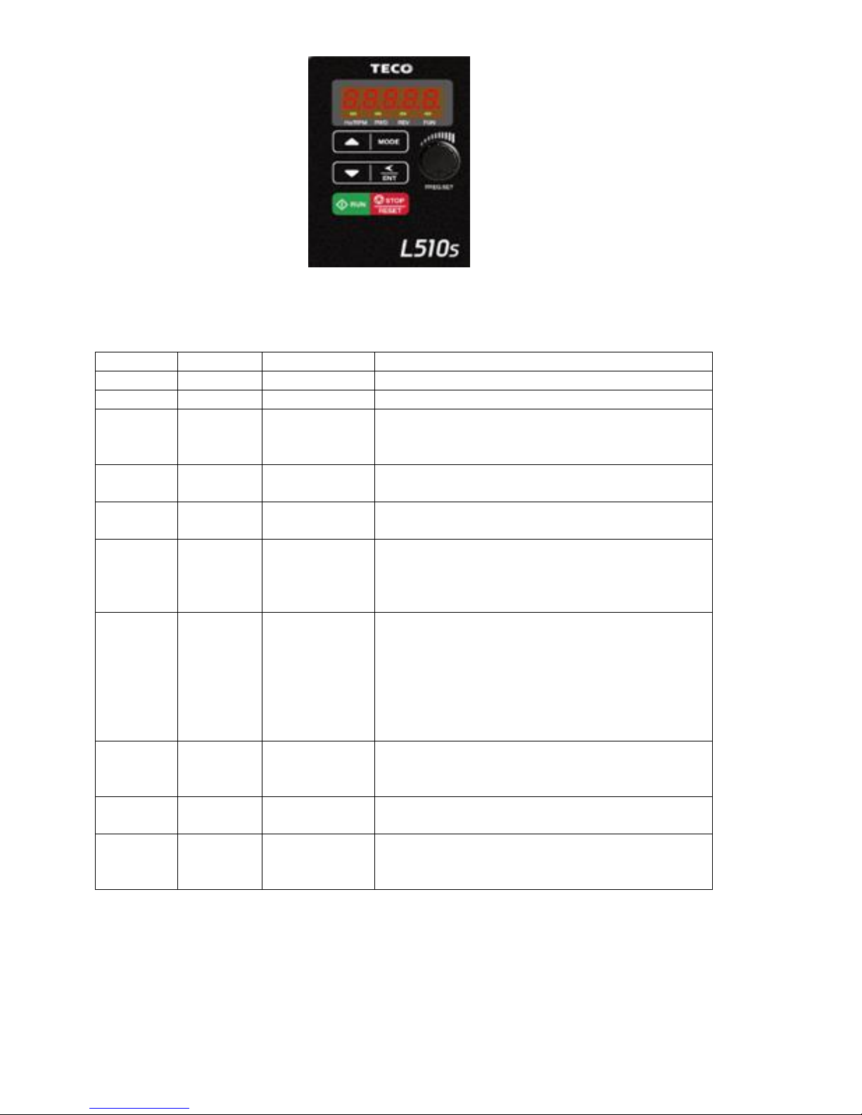
1) To alter parameters:- Press the MODE key,
until the first parameter 00-00 is displayed.
2) Then use the arrow keys </ENT
to select the parameter required
then
Press and hold the </ENT until the preset value is displayed
3) Use the and </ENT keys to alter the setting of the parameters as
per basic quick start parameter list.
Note:- For full parameter list refer to the instruction manual.
4) To save each parameter change, press and hold the </ENT until
the word END is displayed.
5) Use </ENT key to select the next parameter to alter and
follow steps 2 to 4 until all changes are complete.
6) Pressing the MODE key repeatedly will alternate the display
between the preset frequency ( flashing display) and the last parameter
accessed or other selectable displays 0 to 7 when selected by parameter
12-00 according to the table below.
【0】:Disable display 【1】:Output Current
【2】:Output Voltage 【3】:DC voltage
【4】:Temperature 【5】:PID feedback
【6】:AVI 【7】:ACI
Page 5
Page 5 of 9 06/10/17
Basic Quick Start Parameter List
Parameter
Default
Range
Note
00-14
10.0
0.1~3600.0
Acceleration time in Secs
00-15
10.0
0.1~3600.0
Deceleration time in Secs
00-04
0
0-2
0: Forward/Stop-Reverse/Stop
1: Run/Stop-Reverse/Forward
2: 3-Wire Control Mode-Run/Stop
00-12
50/60Hz
0.01~650.00
Max frequency limit.
00-13
0.0
0.00~649.00
Min frequency limit
00-02
0
0-2
Start mode:0: Keypad
1: Remote
2: Communication
00-05
0
0-6
0: Keypad
1: Potentiometer on keypad
2: External AVI analogue signal
3: External ACI analogue signal
4: External up/down frequency control
5: Control by Communication method
6: PID output
07-09
0
0-1
Stop method:-
0: Decel to stop
1: Coast to stop
02-01
**A
**A
Motor overload protection
13-08
00000
Set to factory setting.
1250: 50HZ system.
1360: 60HZ system.
Note:- For Full Parameter List see the Instruction manual
Page 6
Page 6 of 9 06/10/17
Control Modes & Auto Tune
L510s provides two main control modes
Select the relevant control mode for the application, using parameter 00-00 Control mode.
Default control mode is V/f.
V/f can be used for most applications specifically multi-motor
or applications where auto tune is not successful
or when a customized v/f pattern may be required.
Several V/f patterns are available selectable by parameter 01-00.
Select the appropriate V/f pattern based on the application load type and the motor base
frequency of 50 or 60 Hz.
For selections of the V/f patterns . Refer to the instruction manual.
For Vector modes SLV is used for obtaining best performance from a motor.
V/f Mode Parameters:-
Parameter
Default
Range
Note
01-00
1/4
1-7
1= General Purpose. 50 Hz. System
4= General Purpose. 60Hz. System
For full list of preset patterns set by 01-00,
refer to the manual.
7= Customized V/f.
Set parameters 01-01 to 01-09.
SLV ( vector) mode set parameters in parameter Group 2 .
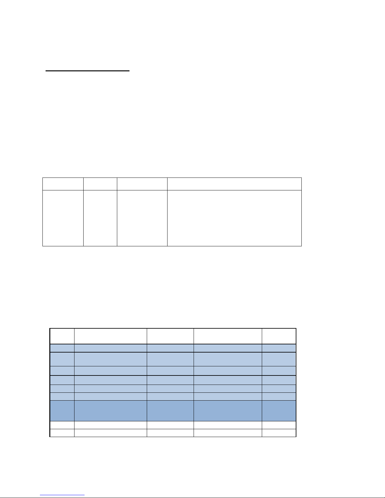
1) Set the motor parameters highlighted below in Group 2 from motor name plate data.
2) Ensure that the motor is connected correctly then,
3) Enable auto tune function by setting parameter 02-07= 1 ( auto tune Enable).
Auto tune type is Static. No rotation of the motor.
After Auto tune is completed successfully ( no errors) the motor stator & resistance values will
be stored automatically in parameters 02-08 & 02-09.
No.
Description
Range
Factory
Setting
Unit
02-00
Motor No Load Current
----
motor nameplate
A
02-01
Motor Rated Current
(OL1)
----
motor nameplate
A
02-03
Motor Rated Speed
----
motor nameplate
Rpm
02-04
Motor Rated Voltage
----
motor nameplate
Vac
02-05
Motor Rated Power
0~22.0
motor nameplate
kW
02-06
Motor Rated Frequency
0~599.0
motor nameplate
02-07
Motor Auto Tuning
0: Disable
1: Static auto
tuning 0
02-08
Stator Resistor Gain
0~600
Rating related value
02-09
Rotor Resistor Gain
0~600
Rating related value
Page 7
Page 7 of 9 06/10/17
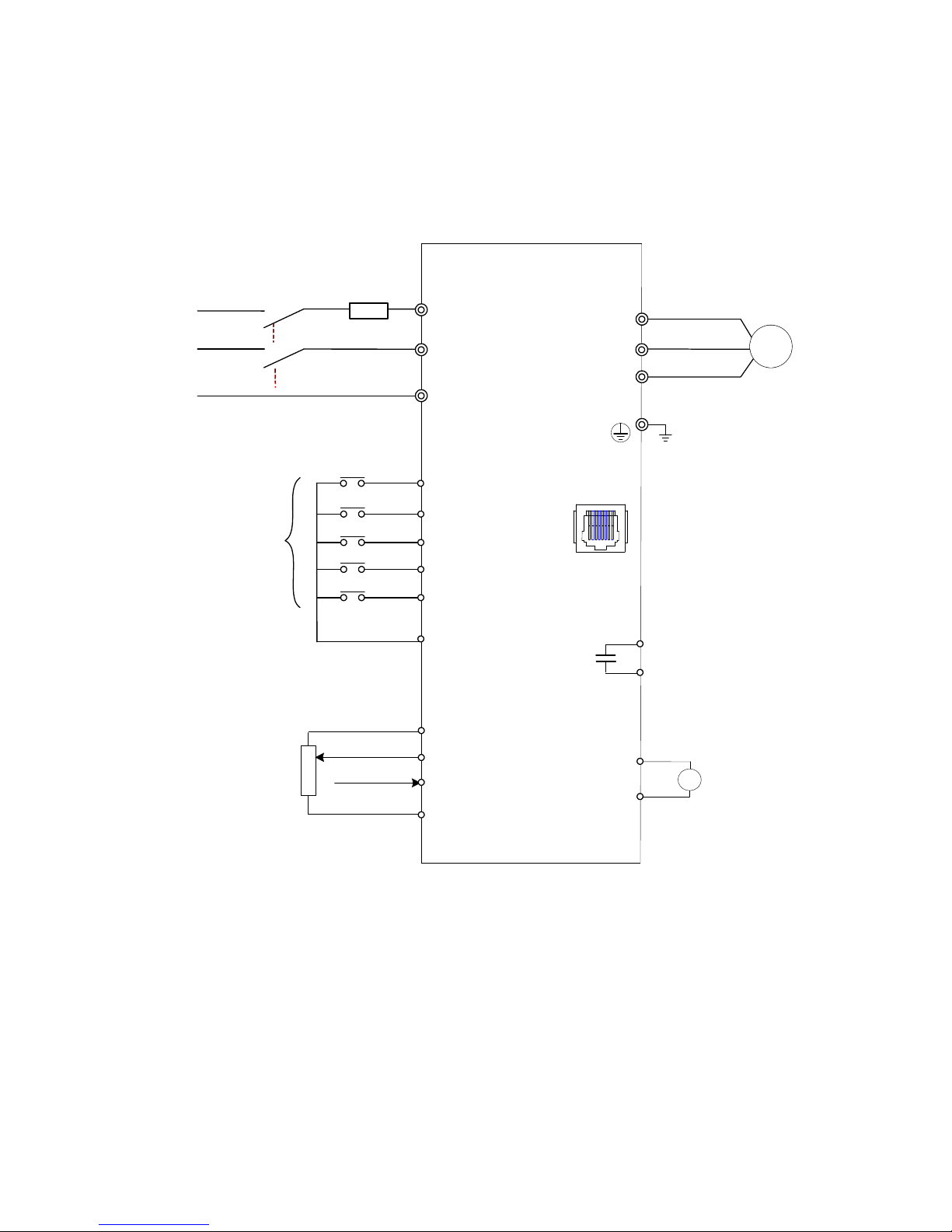
Standard wiring
Single phase (PNP input)
Frames 1&2 ( 0.4~2.2KW)
AC Power
source
L1(L)
S2
S3
S4
+
T1
T2
T3
S5
S1
-
Frequency
reference or PID
Multi-function input
Fuse
Inverter
output
Ground
E
Main
Switch
Power
input
RS485
Pin1 to Pin 8
AO
AGND
+
-
L3(N)
RB
RA
Multi-function output
0~10V
CON2
10V
AVI (0~10V)
ACI (0~20mA)
AGND
AO
Relay output
250VAC/1A
(30VDC/1A)
M
1:Data+
2:Data3:Data+
4:Reserved
5:Reserved
6:Data7:5V
8:GND
+24V *
200V Frames 1&2 models
L510-2P2-SH1F-P / L510-2P5-SH1F-P / L510-2P7-SH1F-P/
L510-201-SH1F-P /L510-202-SH1F-P / L510-203-SH1F-P
Page 8
Page 8 of 9 06/10/17
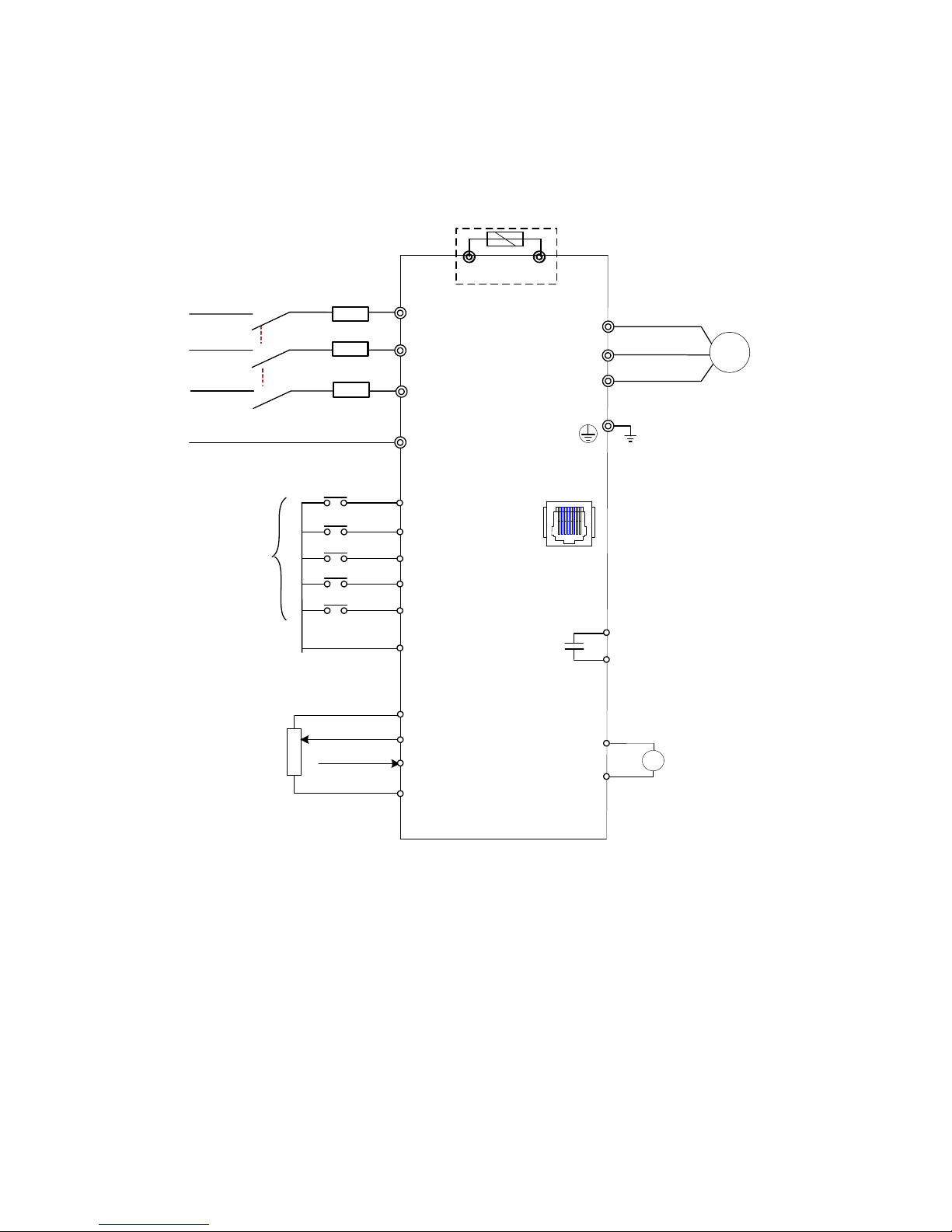
400V Three phase (PNP input)
Frame 2 (0.75 ~2.2KW)
AC Power
source
L1
S2
S3
S4
+
T1
T2
T3
S5
+24V
S1
-
Frequency
reference or PID
Multi-function input
Fuse
Inverter
output
Ground
E
Main
Switch
Power
input
RS485
Pin1 to Pin 8
AO
AGND
+
-
RB
RA
Multi-function output
0~10V
CON2
10V
AVI (0~10V)
ACI (0~20mA)
AGND
AO
Relay output
250VAC/1A
(30VDC/1A)
M
L3
L2
1:Data+
2:Data3:Data+
4:Reserved
5:Reserved
6:Data7:5V
8:GND
P
BR
P
BR
P, BR for 400 series
400V Frame 2 models.
L510-401-SH3F-P /L510-402-SH1F-P / L510-403-SH1F-P
Page 9
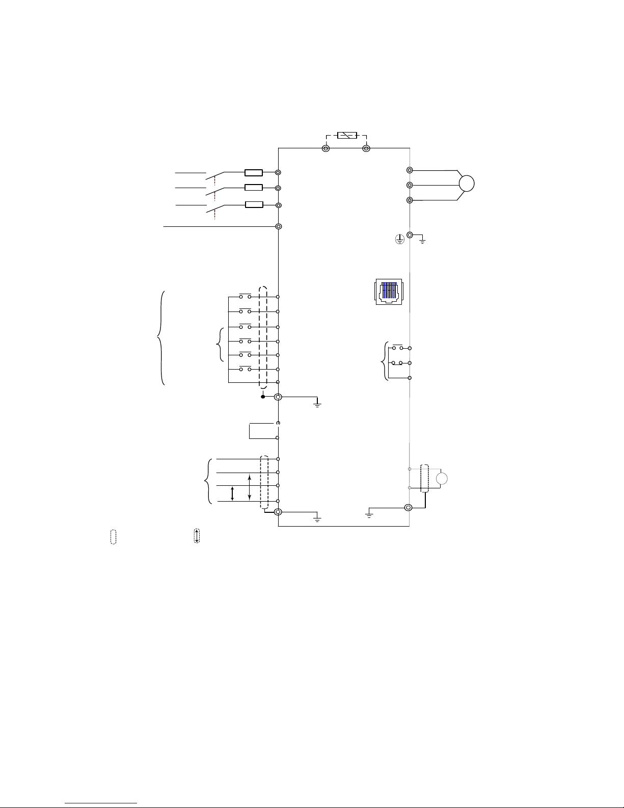
Page 9 of 9 06/10/17
Three phase (PNP input).
Frames 3&4 ( 3.7 ~11KW)
Frequency indicator device
or PID input
Frequency
Indicator
+
T1
10V
AI1
AI2
AGND
0 ~10V
M
0~20mA
-
Inverter
output
Induction
Motor
S3
S4
S5
S6
S2
FWD
(Run/Stop)
S1
250 VAC/1A
(30VDC/1A)
Relay
Output
RS485
CON2
AO
AGND
+
-
0~10VDC
Ground
REV (Run/Stop)
R1A
R1B
R1C
T2
T3
P
BR
Braking resistor
(Option)
SC
AO
Speed Control
Multifunction Input Terminals
E
E
E
P
P
Pin 1 to Pin 8
Reset
1:Data+
2:Data3:Data+
4:RXD0
5:TXD0
6:Data7:5V
8:GND
COM (NPN)
+ 24V (PNP)
Indicates twisted-pair shield wire
P
Indicates shield wire
AC Power
source
L1
Fuse
Main
Switch
Power
input
L3
L2
E
LINK COM to SC
for PNP +24V
use
400V : Frames 3&4 models.
L510-405-SH3F / L510-408-SH3F.
L510-410-SH3F/ L510-415-SH3F.
 Loading...