

TECO L510-1P2-SH1-N, L510-1P5-SH1-N, L510-201-SH1F-P, L510-2P7-SH1F-P, L510-202-SH1F-P Instruction Manual
...Page 1
Page 2

L510s manual
Table of Contents
Chapter 0 Preface…………………………………………………………...
0.1 Preface……………………………………………………….
Chapter 1 Safety Precautions…………………………………………….
1.1 Before Power UP……………………………………………
1.2 During Power UP……………………………………………
1.3 Before Operation……………………………………………
1.4 During Operation……………………………………………
1.5 Inverter Disposal…………………………………………….
Chapter 2 Part Number Definition………………………………………..
Chapter 3 Environment & Installation………………………………......
3.1 Environment…………………………………………………
3.2 Installation……………………………………………………
3.2.1 Installation methods……………………………………
3.2.2 Installation space………………………………………
3.2.3 De-rating curve…………………………………………
3.2.4 Capacitor reforming Guide after long storage………
3.3 Wiring guidelines……………………………………………
3.3.1 Main Considerations........................………………...
3.3.2 Power cables…………………...................................
3.3.3 Control cable selection and wiring…….……………..
3.3.4 Wiring and EMC guidelines…………….…………….
3.3.5 Failure liability………………………………………….
3.3.6 Considerations for peripheral equipment…………...
3.3.7 Ground connection…………………………………...
3.4 Specifications………………………………………………..
3.4.1 Product Specifications………………………………...
3.4.2 General Specifications………………………………..
3.5 Standard wiring……………………………………………..
3.5.1 Single phase(NPN) input……………………………...
3.5.2 Single phase(PNP) input……………………………...
3.5.3 Three phase(NPN) input……………………………...
3.5.4 Three phase(PNP) input………………………………
3.5.5 NPN/PNP selectable models…………………………
3.6 Terminal Description………………………………………..
3.6.1 Description of main circuit terminals…………………
3.6.2 Description of control circuit terminals………………
2.1 Model part number………………………………………….
2.2 Standard Product Specification……………………………
3.5.6 Single / Multi-Pump Dedicated Wiring Diagram
(When 14-00=1)……………………………..…………
0-1
0-1
1-1
1-1
1-1
1-2
1-2
1-2
2-1
2-1
2-2
3-1
3-1
3-3
3-3
3-6
3-9
3-10
3-11
3-11
3-12
3-12
3-13
3-14
3-15
3-16
3-17
3-17
3-19
3-21
3-21
3-22
3-23
3-24
3-25
3-26
3-28
3-28
3-29
I
Page 3

3.7 Outline Dimensions…………………………………………
3.8 EMC filter Disconnection…………………………………...
Chapter 4 Software Index………………………………………………….
4.1 Keypad Description ………………………………………..
4.1.1 Operator Panel Functions…………………………….
4.1.2 Digital Display Description........................................
4.1.3 Digital Display Setup………………………………….
4.1.4 Example of Keypad Operation ………………………
4.1.5 Operation Control……………………………………...
4.2 Programmable Parameter Groups………………………..
4.3 Parameter Function Description………………………….
Chapter 5 Troubleshooting and Maintenance…………………………
5.1 Error Display and Corrective Action………………………
5.1.1 Manual Reset and Auto-Reset……………………….
5.1.2 Keypad Operation Error Instruction………………….
5.1.3 Special conditions……………………………………..
5.2 General troubleshooting……………………………………
5.3 Troubleshooting of the inverter……………………………
5.3.1 Quick troubleshooting of the inverter………………...
5.3.2 Troubleshooting for OC, OL error displays………….
5.3.3 Troubleshooting for OV, LV error…………………….
5.3.4 The Motor can not run…………………………………
5.3.5 Motor Overheating……………………………………..
5.3.6 Motor runs unbalanced………………………………..
5.4 Routine and periodic inspection…………………………..
5.5 Maintenance…………………………………………………
Chapter 6 Peripheral Components………………………………………
6.1 Reactor Specifications……………………………………..
6.2 Electromagnetic Contactor & No fuse circuit breaker…..
6.2.1 EMC External Filter (C2 Level)……………….……...
6.3 Fuse Specification…………………………………………..
6.4 Fuse Specification(UL Model Recommended)…………..
6.5 Braking Resistor…………………………………………….
6.6 Copy Unit(JN5-CU)……….………………………..………
6.7 Communication option….……………….…………………
6.8 RJ45 to USB connecting Cable (1.8m)……….…………
Appendix 1 L510 Parameters Setting List………………………………..
Appendix 2 Instructions for UL…………………………………………….
Appendix 3 L510 MODBUS Communication protocol………………….
Appendix 4 JN5-CM-USB instruction manual……………………………
Appendix 5 510 series accessories manual……………………………..
3-31
3-36
4-1
4-1
4-1
4-2
4-4
4-6
4-8
4-9
4-29
5-1
5-1
5-1
5-4
5-5
5-6
5-7
5-7
5-9
5-10
5-11
5-12
5-13
5-14
5-15
6-1
6-1
6-1
6-1
6-2
6-2
6-3
6-3
6-4
6-4
App1-1
App2-1
App3-1
App4-1
App5-1
II
Page 4

Chapter 0 Preface
0.1 Preface
To extend the performance of the product and ensure personnel safety, please read
this manual thoroughly before using the inverter. Should there be any problem in
using the product that cannot be solved with the information provided in the manual,
contact our technical or sales representative who will be willing to help you.
※Precautions
The inverter is an electrical product. For your safety, there are symbols such as
“Danger”, “Caution” in this manual as a reminder to pay attention to safety
instructions on handling, installing, operating, and checking the inverter. Be sure to
follow the instructions for highest safety.
Danger
Caution
Indicates a potential hazard that could cause death or serious
personal injury if misused.
Indicates that the inverter or the mechanical system might be damaged
if misused.
Danger
Risk of electric shock. The DC link capacitors remain charged for five
minutes after power has been removed. It is not permissible to open the
equipment until 5 minutes after the power has been removed.
Do not make any connections when the inverter is powered on. Do not check
parts and signals on circuit boards during the inverter operation.
Do not disassemble the inverter or modify any internal wires, circuits, or
parts.
Ensure that the Inveter Ground terminal is connected correctly.
Caution
Do not perform a voltage test on parts inside the inverter. High voltage can
destroy the semiconductor components.
Do not connect T1, T2, and T3 terminals of the inverter to any AC input
power supply.
CMOS ICs on the inverter’s main board are susceptible to static electricity. Do
not touch the main circuit board.
0-1
Page 5

Chapter 1 Safety Precautions
1.1 Before Power Up
Danger
Make sure the main circuit connections are correct. Single phase L1(L),L3(N), and Three
phase L1(L),L2,L3(N); 400V : L1,L2,L3 are power-input terminals and must not be mistaken for
T1,T2 and T3. Otherwise, inverter damage can result.
Caution
The line voltage applied must comply with the inverter’s specified input voltage.(See the
nameplate)
To avoid the front cover from disengaging, or other damge do not carry the inverter by its
covers. Support the drive by the heat sink when transporting. Improper handling can damage
the inverter or injure personnel and should be avoided.
To avoid the risk of fire, do not install the inverter on a flammable object. Install on
nonflammable objects such as metal.
If several inverters are placed in the same control panel, provide heat removal means to
maintain the temperature below 50 degree C to avoid overheat or fire.
When disconnecting the remote keypad, turn the power off first to avoid any damage to the
keypad or the inverter.
Installation limitation, -10~50℃ (cooling fan inside model), -10~40℃ (without cooling fan
inside model)
Warning
This product is sold subject to EN 61800-3 and EN 61800-5-1.
In a domestic environment this product may cause radio interference in which
case the user may be required to apply corrective measures.
Caution
Work on the device/system by unqualified personnel or failure to comply with warnings can
result in severe personal injury or serious damage to material. Only suitably qualified
personnel trained in the setup, installation, commissioning and operation of the product should
carry out work on the device/system.
Only permanently-wired input power connections are allowed.
1.2 During Power Up
Danger
When the momentary power loss is longer than 2 seconds, the inverter will not have sufficient
stored power for its control circuit. Therefore, when the power is re-applied, the run operation
of the inverter will be based on the setup of following parameters:
Run parameters. 00-02 or 00-03.
Direct run on power up. Parameter. 07-04 and the status of external run switch,
Note-: the start operation will be regardless of the settings for parameters
07-00/07-01/07-02.
Danger. Direct run on power up.
If direct run on power up is enabled and inverter is set to external run
with the run FWD/REV switch closed then the inverter will restart.
Danger
Prior to use, ensure that all risks and safety implications are considered.
1-1
Page 6

When the momentary power loss ride through is selected and the power loss is short, the
inverter will have sufficient stored power for its control circuits to function, therefore, when the
power is resumed the inverter will automatically
restart depending on the setup of parameters 07-00 & 07-01.
1.3 Before Operation
Caution
Make sure the model and inverter capacity are the same as that set in parameter 13-00.
Note : On power up the supply voltage set in parameter 01-01 will flash on display
for 2 seconds.
1.4 During Operation
Danger
Do not connect or disconnect the motor during operation. Otherwise, It may cause the inverter
to trip or damage the unit.
Danger
To avoid electric shock, do not take the front cover off while power is on.
The motor will restart automatically after stop when auto-restart function is enabled. In this
case, care must be taken while working around the drive and associated equipment .
The operation of the stop switch is different than that of the emergency stop switch. The stop
switch has to be activated to be effective. Emergency stop has to be de-activated to become
effective.
Caution
Do not touch heat radiating components such as heat sinks and brake resistors.
The inverter can drive the motor from low speed to high speed. Verify the allowable speed
ranges of the motor and the associated machinery.
Note the settings related to the braking unit.
Risk of electric shock. The DC link capacitors remain charged for five minutes after power has
been removed. It is not permissible to open the equipment until 5 minutes after the power has
been removed.
Caution
The Inverter should be used in environments with temperature range from (14-104℉) or (-10
to 40℃) and relative humidity of 95%.
Note: models with fan : -10~50℃ , models without fan : -10~40℃
Danger
Make sure that the power is switched off before disassembling or checking any components.
1.5 Inverter Disposal
Caution
Please dispose of this unit with care as an industrial waste and according to your required local
regulations.
The capacitors of inverter main circuit and printed circuit board are considered as hazardous
waste and must not be burnt.
The Plastic enclosure and parts of the inverter such as the cover board will release harmful
gases if burnt.
1-2
Page 7

Chapter 2 Part Number Definition
2.1 Model Part Number
Note:
1. 102/1P5/101/2P2/2P5/201/202/203/401/402/403 models need to select digital input type
by code⑦(NPN or PNP input).
2. 205/208/210/405/408/410/415 models need to select digital input type by control terminal,
please refer the wiring diagram of chapter 3.
3. If the pump parallel connection is necessary, please select the model of pump application by
code⑧.
4. Standard type: Built-in BACnet communication, without PUMP parallel function.
PUMP type: Built-in PUMP parallel function, without BACnet communication.
2-1
Page 8
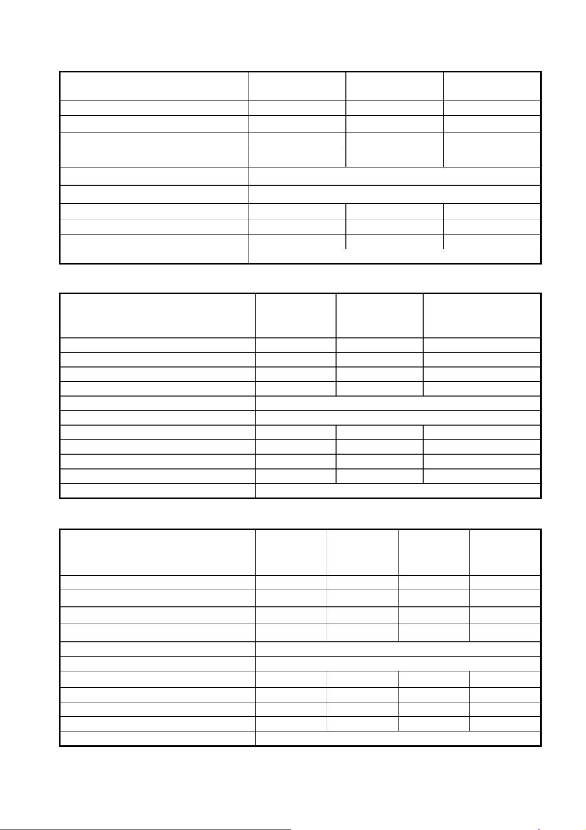
2.2 Standard Product Specification
Supply
Model
Voltage
(Vac)
L510-1P2-SH1-N
L510-1P5-SH1-N 0.5 0.4
L510-101-SH1-N 1 0.75
1ph,
100~120V
+10%/-15%
L510-2P2-SH1F-P
Frequency
(Hz)
(HP)
(KW)
NPN PNP Built-in None
0.25 0.2
0.25 0.2
◎
◎
◎
L510-2P5-SH1F-P 0.5 0.4
L510-2P7-SH1F-P 0.75 0.55
L510-201-SH1F-P 1 0.75
L510-202-SH1F-P 2 1.5
L510-203-SH1F-P 3 2.2
1ph,
200~240V
L510-2P2-SH1-N 0.25 0.2
+10%/-15%
L510-2P5-SH1-N 0.5 0.4
L510-2P7-SH1-N 0.75 0.55
50/60Hz
L510-201-SH1-N 1 0.75
L510-202-SH1-N 2 1.5
L510-203-SH1-N 3 2.2
L510-2P2-SH3-N
0.25 0.2
L510-2P5-SH3-N 0.5 0.4
L510-201-SH3-N 1 0.75
L510-202-SH3-N 2 1.5
3ph,
◎
◎
◎
◎
◎
◎
◎
◎
◎
◎
200~240V
L510-203-SH3-N 3 2.2
+10%/-15%
L510-205-SH3 5 3.7
L510-208-SH3 8 5.5
L510-210-SH3 10 7.5
L510-401-SH3-N
1 0.75
L510-402-SH3-N 2 1.5
L510-403-SH3-N 3 2.2
◎
◎
◎
◎
◎
◎
◎
L510-401-SH3F-P 1 0.75
L510-402-SH3F-P 2 1.5
L510-403-SH3F-P 3 2.2
L510-405-SH3 5 3.7
L510-408-SH3 8 5.5
3ph,
380~480V
+10%/-15%
50/60Hz
L510-410-SH3 10 7.5
L510-415-SH3 15 11
L510-405-SH3F 05 3.7
L510-408-SH3F 08 5.5
L510-410-SH3F 10 7.5
L510-415-SH3F 15 11
◎
◎
◎
◎
◎
◎
◎
◎
Model Filter
◎
◎
◎
◎
◎
◎
◎
◎
◎
◎
◎
◎
◎
◎
◎
◎
◎
◎
◎
◎
◎
◎
◎
◎
◎
◎
◎
◎
◎
◎
◎
◎
◎
◎
◎
◎
◎
◎
◎
◎
◎
◎
◎
◎
◎
◎
◎
◎
◎
◎
◎
◎
◎
◎
◎
◎
◎
Short circuit capacity is below 5000A/120V or 5000A/240V or 5000A/480V, for 100~120V models is
120V; 200~240V models is 240V, 380~480V models is 480V.
2-2
Page 9

Model
(Built-in PUMP
Parallel Function)
L510-1P2-SH1-NP
L510-1P5-SH1-NP 0.5 0.4 ◎ ◎
L510-101-SH1-NP 1 0.75 ◎ ◎
L510-2P2-SH1F-PP
Supply
voltage(Vac)
1ph,
100~120V
+10%/-15%
Frequency
(Hz)
(Hp) (KW)
0.25 0.2 ◎ ◎
0.25 0.2 ◎ ◎
Digital input
model
Filter
NPN PNP NPN PNP
L510-2P5-SH1F-PP 0.5 0.4 ◎ ◎
L510-2P7-SH1F-PP 0.75 0.55 ◎ ◎
L510-201-SH1F-PP 1 0.75 ◎ ◎
L510-202-SH1F-PP 2 1.5 ◎ ◎
L510-203-SH1F-PP 3 2.2 ◎ ◎
1ph,
200~240V
L510-2P2-SH1-NP 0.25 0.2 ◎ ◎
+10%/-15%
L510-2P5-SH1-NP 0.5 0.4 ◎ ◎
L510-2P7-SH1-NP 0.75 0.55 ◎ ◎
50/60Hz
L510-201-SH1-NP 1 0.75 ◎ ◎
L510-202-SH1-NP 2 1.5 ◎ ◎
L510-203-SH1-NP 3 2.2 ◎ ◎
L510-2P2-SH3-NP
0.25 0.2 ◎ ◎
L510-2P5-SH3-NP 0.5 0.4 ◎ ◎
L510-201-SH3-NP 1 0.75 ◎ ◎
L510-202-SH3-NP 2 1.5 ◎ ◎
3ph,
200~240V
L510-203-SH3-NP 3 2.2 ◎ ◎
+10%/-15%
L510-205-SH3P 5 3.7 ◎ ◎ ◎
L510-208-SH3P 8 5.5 ◎ ◎ ◎
L510-210-SH3P 10 7.5 ◎ ◎ ◎
L510-401-SH3-NP
1 0.75 ◎ ◎
L510-402-SH3-NP 2 1.5 ◎ ◎
L510-403-SH3-NP 3 2.2 ◎ ◎
L510-401-SH3F-PP 1 0.75 ◎ ◎
L510-402-SH3F-PP 2 1.5 ◎ ◎
L510-403-SH3F-PP 3 2.2 ◎ ◎
L510-405-SH3P 5 3.7 ◎ ◎ ◎
L510-408-SH3P 8 5.5 ◎ ◎ ◎
3ph,
380~480V
+10%/-15%
50/60Hz
L510-410-SH3P 10 7.5 ◎ ◎ ◎
L510-415-SH3P 15 11 ◎ ◎ ◎
L510-405-SH3FP 05 3.7 ◎ ◎ ◎
L510-408-SH3FP 08 5.5 ◎ ◎ ◎
L510-410-SH3FP 10 7.5 ◎ ◎ ◎
L510-415-SH3FP 15 11 ◎ ◎ ◎
Short circuit capacity is below 5000A/120V or 5000A/240V or 5000A/480V, for 100~120V models is
120V; 200~240V models is 240V, 380~480V models is 480V.
2-3
Page 10

Chapter 3 Environment & Installation
3.1 Environment
Installation environment has a direct effect on the correct operation and the life expectancy of the
inverter, Install the inverter in an environment complying with the following conditions:
Protection
Protection
class
Operating
temperature
IP20 Open Type
Suitable environment
-10~40°C (-10~50°C with fan) (non-freezing)
If several inverters are installed in the same control panel, ensure
adequate spacing and provide the necessary cooling and ventilation for
successful operation.
Storage
temperature
Relative
Humidity
Altitude
Vibration
-20~60°C
Max 95% (without condensation)
Altitude:Below 1000m (3281ft)
It is required to reduce 2% of inverter
rated current at each additional
100m. The maximum altitude is
3000m
Frequency: 10Hz - 150Hz - 10Hz
Amplitude(0.3mm): 10Hz ≦f ≦57Hz
Acceleration(2G): 57Hz ≦f ≦150Hz
(According to IEC60068-2-6 standard)
Installation site
Install in an environment that will not have an adverse effect on the operation of the unit
and ensure that there is no exposure to areas such as that listed below:-
Direct sunlight, Rain or moisture
Oil mist and salt
Dust, lint fibres, small metal filings and corrosive liquid and gas
Electromagnetic interference from sources such as welding equipment
Radioactive and flammable materials
Excessive vibration from machines such as stamping, punching machines
Add vibration-proof pads if necessary
3-1
Page 11
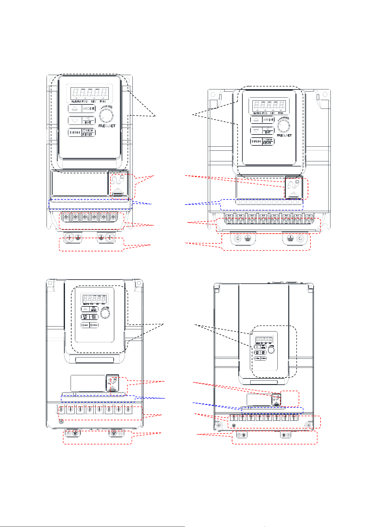
Product Overview
Frame 1
Operator
Panel
RS485
port
TM2
terminal
TM1
terminal
Ground
terminal
Frame 2
Operator
Panel
RS485
Frame 3
port
TM2
terminal
TM1
terminal
Ground
terminal
Frame 4
3-2
Page 12
3.2 Installation
r
r
r
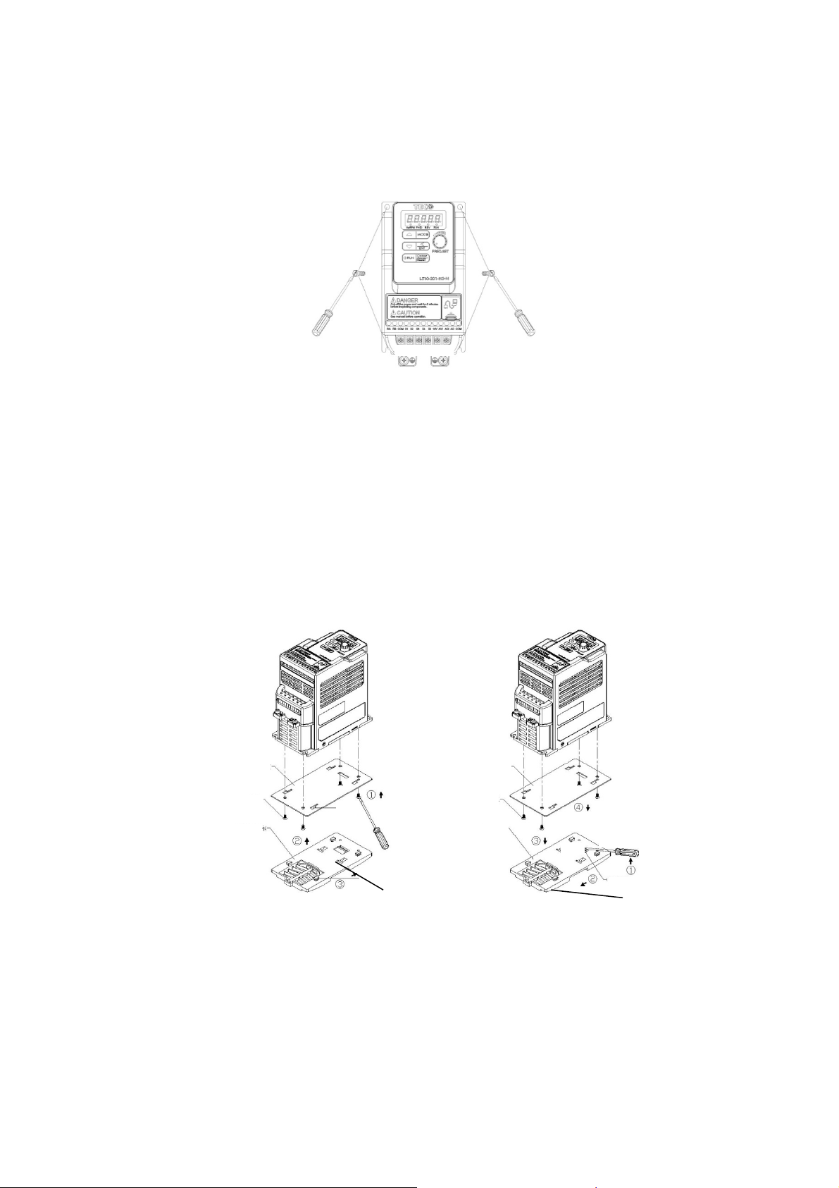
3.2.1 Installation methods
Frame1. Mounting on a flat surface.
Screw: M4
Din rail type installation:
Din rail kit includes a plastic and a metal adaptor plates.
Assembly Steps:-
1) Attach the metal adaptor plate to the inverter base with the screws provided.
2) Attach the plastic Din rail adaptor to the metal adaptor plate.
3) Push the plastic adaptor forward to lock into position.
Disassembly Steps:-
1) Unlock by pushing the snap hooks
2) Retract and remove the plastic Din rail adaptor.
3) Unscrew the metal plate &Remove
Assembly:-
1. Metal plate adapto
3. screws
2. Plastic adapto
Disassembly:-
1. Metal plate adaptor
3. screws
2. Plastic adapto
Snap hooks
Note:
JN5-DIN-L01 (Frame 1 Din rail kit part number), including the following parts
1. Metal plate adaptor
2. Plastic adaptor
3. Chamfer head screw: M3×6
Snap hooks
3-3
Page 13

Frame 2. Mounting on a flat surface.
Screw: M4
Din rail type installation:
Din rail kit includes a plastic adaptor plate as an attachment for the inverter base.
Refer to Diagram below:-
Assembly:-
Plastic Adaptor plate
Disassembly:-
Snap hook
Middle Snap hook
Snap hook
Din Rail Mounting & Dismounting as shown in the diagram below:-Use a 35mm Din Rail.
Mounting
Dismounting
Plastic adaptor plate.
JN5-DIN-L02 (Frame 2 Din rail kit part number)
3-4
Page 14

Frame 3. Mounting on a flat surface
M4 螺丝
M4 screw
Frame 4. Mounting on a flat surface
M4 螺丝
M4 screw
3-5
Page 15
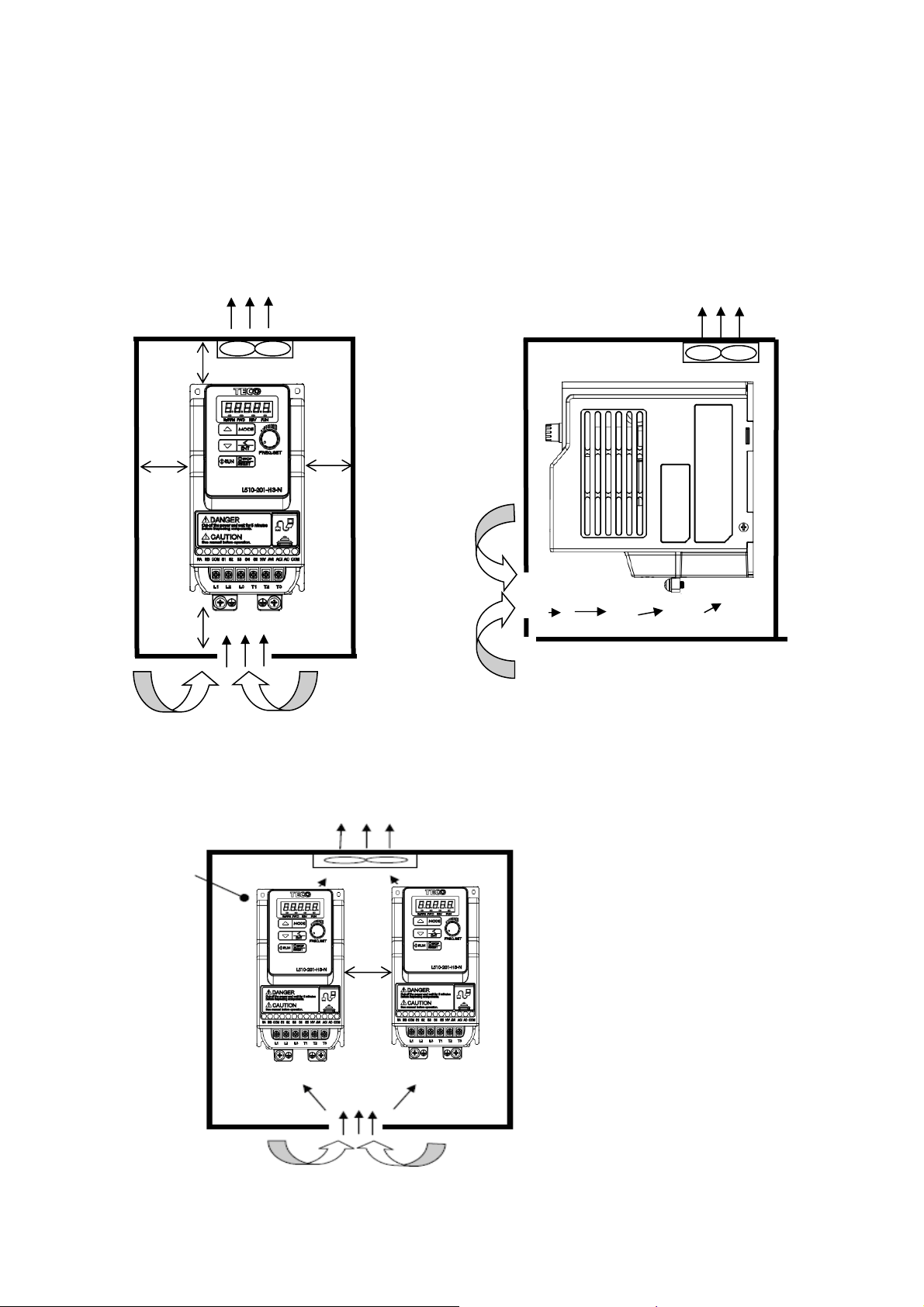
3.2.2 Installation space
Provide sufficient air circulation space for cooling as shown in examples below.
Install the Inverter on surfaces that provide good heat dissipation.
Single unit Installation
Install the inverter verticality to obtain effective cooling.
Fan Fan
12cm
12cm
Side by side Installation
CONTROL
PANEL
Front view
5cm 5cm
Fan
5cm
Side view
Provide the necessary
physical space and cooling
based on the ambient
temperature and the heat
loss in the panel
3-6
Page 16
Installation for Grounding kit
Grounding kit:
As bellowed diagram, use screw to install EMC metal plate into heatsink.
Frame 1 Frame 2
3-7
Page 17

Grounding kit option installation diagram and instruction (Example)
Frame 1 Frame 2
1. Grounding kit to be mounted on the drive (earth casing), please follow the diagram to
install .
2. Unshielded power supply lines or cable.
3. Unshielded wires or cable for the output of the relay contacts.
4. Attach and earth the shielding of cables 3 and 4 as close as possible to the drive:
Strip the cable to expose the shielding;
Attach the cable to the plate 1, attaching the clamp on the stripped part of the
shielding.
The shielding must clamped tightly enough to metal sheet to ensure good contact.
5. Shielded power supply cable for connecting motor which connect to earth at both
ends. The shielding must be continuous, and if intermediate terminals are used, they
must be placed in EMC shielded metal boxes.
6. Shielded cable for control-signal wiring. For applications requiring several conductors,
use cables with small cross-section (0.5 mm^2, 20 AWG). For cables 3 and 4, the
shielding must be connected to earth at both ends. The shielding must be continuous,
and if intermediate terminals are used, they must be placed in EMC shielded metal
boxes.
Notice:
● If using external EMC input filter, it must be mounted under the drive and connected
directly to the line supply via an unshielded cable. Link 6 on the drive is then via the
output cable.
● The HF equipotential earth connection between the drive, motor and cable shielding
does not remove the need to connect the PE conductors (green-yellow) to the
appropriate terminals on each device.
3-8
Page 18
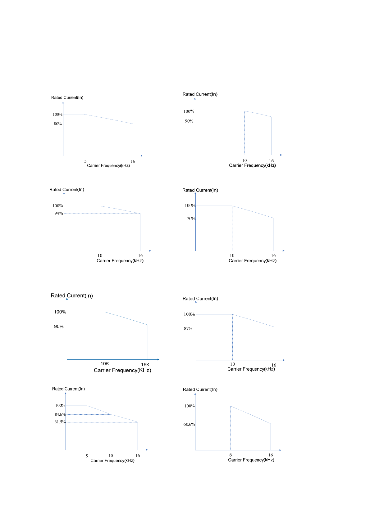
3.2.3 De-rating curve
Curves below show the applicable output current de-rate due to setting of carrier
frequency and the ambient operating temperatures of 40 and 50 degree C.
2P2/2P5/2P7/201 (40℃) 1P2/1P5(40℃)、202/203 (50℃)
208(50℃) 210(50℃)
401/2/3(50℃) 405(50℃)
408(50℃) 410(50℃)
3-9
Page 19

415(50℃) 101/205(50℃)
Rated Current(In)
100%
5K 10K 16K
Carrier Frequency(Hz)
Note: 101 and 205 type does not need to decrease the current rating in 50 degrees
ambient temperature.
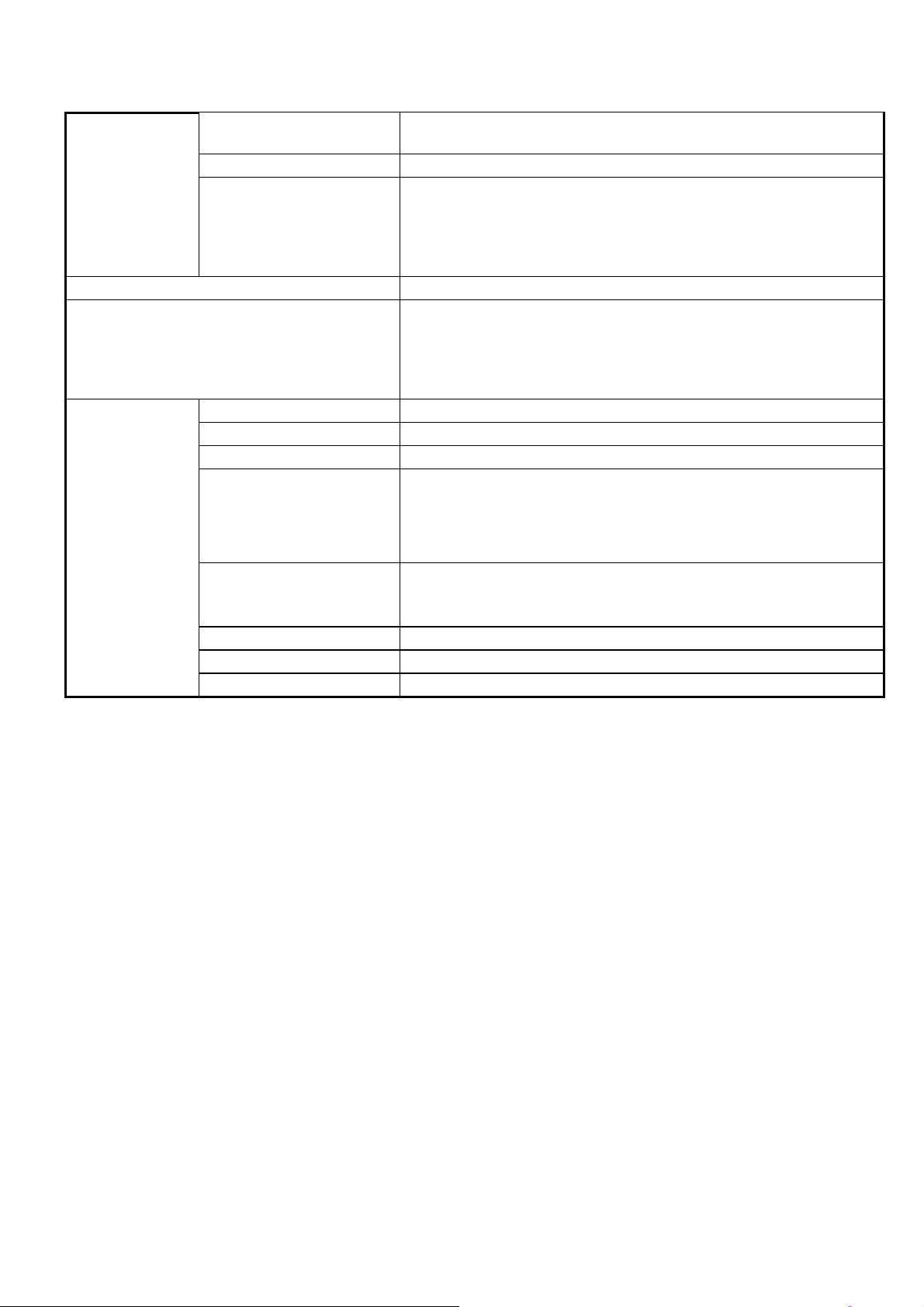
3.2.4 Capacitor reforming Guide after long storage
For correct performance of this product after long storage before use it is important that
Inverter Capacitors are reformed according to the guide below:
Storage
time
≦1year
Between
1-2 years
Apply rated voltage(Note1) of inverter in the normal way
Apply rated voltage of inverter to the product for one hour before using
the inverter
Use a variable AC power supply to
1. Connecting 25% rated voltage of inverter for 30 minutes.
≧2 years
2. Connecting 50% rated voltage of inverter for 30 minutes.
3. Connecting 75% rated voltage of inverter for 30 minutes.
4. Connecting 100% rated voltage of inverter for 210 minutes.
Once the procedures completed, inverter just can be used normally.
Note1:Rated voltage: please refer the rated voltage according to model label of inverter.
Procedure to re-apply voltage
3-10
Page 20
3.3 Wiring Guidelines
3.3.1 Main considerations
1 Tightening Torque for Screw terminals:Refer to the tables 3-1, when using a
screwdriver or any other suitable tools to make connections.
2 Power terminals:
Single phase : L1 (L), L3 (N)
Three-phase 200V models: L1 (L), L2, L3 (N)
400V models: L1, L2, L3
3 For all cabling use copper wires and the cable size shall be according to the table
below rated at 105 degrees Celsius.
4 Power & Control cable Minimum rated voltage
240V AC system, 300V AC.
480V AC system, 600V AC.
5 Control cables should be separated from the power cables. Do not place them in the
same cable tray or cable trunking to prevent against electrical interference.
Table 3-1
Frame
size
Frame1
Frame2
Frame3
Frame4
Cable Size Tightening torque Cable Size Tightening torque
AWG mm² kgf.cm Ibf.in Nm AWG mm²
22~10 0.34~6
18~8 0.82~8.4 18 15.58 1.76
14~6 2~13.3 24.48 21.24 2.4
6 The maximum RMS symmetrical Current Ratings and voltage are listed as below:
Device Rating
voltage HP
110V 0.2~1 5000A 120V
TM1 TM2
Nm
14 12.15 1.37
12.24 10.62 1.2
kgf.cm Ibf.in
24~12 0.5~2.5 4.08 3.54 0.4
24~12 0.5~2.5 5.1 4.43 0.5
Short circuit Rating Maximum Voltage
220V 0.2~10 5000A 240V
440V 1~15 5000A 480V
7 Electrical ratings of terminals:
Horsepower Power Specification Voltage (Volt) Current(A)
0.25/0.5/1 220~240V
1 100~120V 20
2/3 220~240V 30
1/2/3 380~480V 600 28
5 220~240V 300 45
7.5/10 220~240V 300 65
5.5/7.5 380~480V 600 45
10/15 380~480V 600 65
30
300
3-11
Page 21

3.3.2 Power Cables.
Supply power cable must be connected to TM1 terminal block, terminals L1(L) and L3(N) for
single phase 200V supply, L1(L), L2, L3(N) for three phase 200V supply and L1, L2, L3 for
three phase 400V supply.
Motor cable must be connected to TM1 terminals. T1, T2, T3.
Warning:- Connection of Supply line cable to terminals T1,T2& T3 will result in serious
damage to the drive components.
Example power connections:- Inverter with dedicated power line.
Power
MCCB
Inverter IM
Install a Supply RFI filter or Isolation transformer when the power source is shared
with other high power electrical equipment as shown below.
MCCB
Inverter IM
Insulation transformer
Power
MCCB
RFI
Filter
Power
Inverter IM
Machine
3.3.3 Control Cable selection and Wiring.
Control cables should be connected to terminal block TM2.
Choose power & Control cables according to the following criteria:-
Use copper wires with correct diameter and temperature rating of 60/75°C.
Minimum cable voltage rating for 200V type inverters should be 300VAC.
Route all cables away from other high voltage or high current power lines
to reduce interference effects.
Machine
Use a twisted pair shielded cable and connect the shield (screen) wire to the ground
terminal at the inverter end only. Cable length should not exceed 50 meters.
Connect the shield to inverter
Shielding sheath
ground terminal
Protective covering
Do not connect this end
3-12
Page 22

3.3.4 Wiring and EMC guidelines.
For effective interference suppression, do not route power and control cables in the same
conduit or trunking.
To prevent radiated noise, motor cable should be put in a metal conduit. Alternatively an
armored or shielded type motor cable should be used.
For effective suppression of noise emissions the cable armor or shield must be grounded at
both ends to the motor and the inverter ground. These connections should be as short as
possible.
Motor cable and signal lines of other control equipment should be at the least 30 cm apart.
L510s has a built in Class “A” EMC filter to first Environment Restricted. (Category C2).
For some installations such as residential,(Category C1) an optional external Class “B” type
filter will be necessary. Please consult your local supplier.
Typical Wiring.
L1(L)
L3(N)
E
1
2
L1(L)
Drive
T1T2
3
4
5 6
M
L3(N)
T3
E
E
7
PE
8
1.Protective Earth Conductor.
Conductor size for enclosure &
Backplate must comply with the local electrical
standards. Min 10mm².
2.Backplate. Galvanised steel (Unpainted).
3.Ferrite core / Output reactor
ferrite cores can be used to reduce
radiated noise due to long motor cables.
If ferrite core is used loop motor wires, 3 times
round the core. Install core as close to the
inverter as possible
Output reactors provide additional
benefit of reducing dv/dt for protection of motor
windings.
4.Metal Cable clamp. no more than 150mm from
the inverter.
Note: If no enclosure & backplate is used then
connect the cable shield by a good 360 º
termination to the Inverter output terminal E.
5.Screened (Shielded four core cable).
6.Separate Protective Earth wire, routed outside
motor cable separated be at least 100mm.
Note:- this is the preferred method specially
for large output cables and long length.
Multi-core screened (3 core & protective
earth) can be used for small power and short
length.
7.Connect the cable shield by a good
360º termination and connect to the motor
protective earth terminal.
This link must be as short as possible.
8.Motor Earth terminal(Protective Earth).
3-13
Page 23

3.3.5 Failure liability
Teco bears no responsibility for any failures or damaged caused to the inverter if the
recommendations in this instruction manual have not been followed specifically
points listed below,
If a correctly rated fuse or circuit breaker has not been installed between the power
source and the inverter.
If a magnetic contactor, a phase capacitor, burst absorber and LC or RC circuits have
been connected between the inverter and the motor.
If an incorrectly rated three-phase squirrel cage induction motor has been used
Note:
When one inverter is driving several motors, the total current of all motors running
simultaneously must be less than the rated current of the inverter, and each motor has
to be equipped with a correctly rated thermal overload relay.
3-14
Page 24

3.3.6 Considerations for peripheral equipment
Power
Circuit
Breaker
& RCD
(
(For detailed information for the above peripheral equipment refer to Chapter 6)
Magnetic
contactor
AC reactor for
power quality
improvement
Input noise
filter
Inverter
Motor
Ensure that the supply voltage is correct.
A molded-case circuit breaker or fused disconnect
must be installed between the AC source and the
inverter
Use a molded-case circuit breaker that conforms to
the rated voltage and current of the inverter.
Do not use the circuit breaker as the run/stop switch
for the inverter.
Residual Current Circuit Breaker(RCD)
Current setting should be 200mA or above and the
operating time at 0.1 second or longer to prevent
malfunctions.
Normally a magnetic contactor is not needed.
A contactor can be used to perform functions such
as external control and auto restart after power
failure.
Do not use the magnetic contactor as the run/stop
switch for the inverter.
When a 200V/400V inverter with rating below 15KW
is connected to a high capacity power source
(600kVA or above) then an AC reactor can be
connected for power factor improvement and
reducing harmonics.
L510 inverter has a built-in filter to Class “A” first
Environment. (CategoryC2)
To satisfy the required EMC regulations for your
specific application you may require an additional
EMC filter.
Connect the single phase power to Terminals, L1(L)
& L3(N) and three phase power to Terminals :
(200V : L1(L),L2,L3(N) or 400V : L1,L2,L3)
Warning! Connecting the input terminals T1, T2,
and T3 to AC input power will damage the inverter.
Output terminals T1, T2, and T3 are connected to U,
V, and W terminals of the motor.
To reverse the motor rotation direction just swap
any two wires at terminals T1, T2, and T3.
Ground the Inverter and motor correctly.
Ground Resistance for 200V power<100 Ohms.
Three-phase induction motor. Voltage drop on motor
due to long cable can be calculated.
Volts drop should be < 10%.
Phase-to-phase voltage drop (V) =
3 ×resistance of wire (Ω/km)×length of line
(m)×current×10
-3
3-15
Page 25

3.3.7. Ground connection
Inverter Ground terminal must be connected to installation ground correctly and
according to the required local wiring regulations.
Ground cable size must be according to the required local wiring
regulations. Ground connection should be as short as possible.
Do not share the ground of the inverter with other high current loads (Welding
machine, high power motors). Ground each unit separately.
Ensure that all ground terminals and connections are secure
Do not make ground loops when several inverters share a common ground point.
Note: Please leave at least 5cm while installing inverter side by side in order to provide
enough cooling space.
(a) Correct (b) Correct (c) Incorrect
3-16
Page 26

3.4 Specifications
3.4.1 Product Specifications
100V Class : Single phase
Model :
L510-□□□-SH1-N(P)/P(P)
Horse power (HP)
Suitable motor capacity (kW)
Rated output current (A)
Rated capacity (kVA)
Input voltage range(V)
Output voltage range(V)
Input current (A)*
Weight(Kg)
Allowable momentary power loss time (s)
Enclosure
200V Class : Single phase. F : Standards for built-in filter
Model :
L510-□□□-SH1X-N(P)/P(P)
1P2 1P5 101
0.25 0.5 1
0.2 0.4 0.75
1.8 2.6 4.3
0.68 1.00 1.65
Single Phase : 100~120V(+10%-15%),50/60HZ
Three phase 0~ 24 0V
9.5 13 19
0.9 0.9 1.4
1.0 1.0 1.0
2P2 2P5
2P7
IP20
201 202 203
Horse power (HP)
Suitable motor capacity (kW)
Rated output current (A)
Rated capacity (kVA)
Input voltage range(V) Si n gle P has e : 200~240V(+10%-15%),50/60HZ
Output voltage range(V) Three phase 0~ 24 0V
Input current (A)
Weight(kG)
Weight with filter(kG)
Allowable momentary power loss time (s)
Enclosure
200V Class : Three phase
Model :
L510-□□□-SH3-N(P)/P(P)
Horse power (HP)
Suitable motor capacity (kW)
Rated output current (A)
Rated capacity (kVA)
Input voltage range(V) Three phase : 200 ~ 240 V (+1 0% -15 % ),5 0 /60 H Z
Output voltage range(V) Three phase 0~ 24 0V
Input current (A)
0.25 0.5
0.2 0.4
1.8 2.6
0.68 1.00
4.9 7.2
0.9 0.9 0.9
1.0 1.0 1.0
1.0 1.0
0.75
0.55
3.4
1.30
9
1.0
1 2 3
0.75 1.5 2.2
4.3 7.5 10.5
1.65 2.90 4.00
11 15.5 21
0.9 1.4 1.4
1.0 1.5 1.5
1.0 2.0 2.0
IP20
2P2 2P5 201 202 203
0.25 0.5 1 2 3
0.2 0.4 0.75 1.5 2.2
1.8 2.6 4.3 7.5 10.5
0.68 1.00 1.65 2.90 4.00
3.0 4.0 6.4 9.4 12.2
Weight(kG)
Allowable momentary power loss time (s)
Enclosure
0.9 0.9 0.9 1.4 1.4
1.0 1.0 1.0 2.0 2.0
IP20
3-17
Page 27
Model :
L510-□□□-SH3(P)
Horse power (HP)
Suitable motor capacity (kW)
Rated output current (A)
Rated capacity (kVA)
205 208 210
5 7.5 10
3.7 5.5 7.5
17.5 26 35
6.67 9.91 13.34
Input voltage range(V)*
Output voltage range(V)
Input current (A)
Weight(kG)
Allowable momentary power loss time (s)
Enclosure
Three phase : 200~240V (+10%-15%),50/60HZ
19.3 28.6 38.5
2.2 6.3 6.3
2.0 2.0 2.0
400V Class : Three phase. F : Standards for built-in filter
Model :
L510-□□□-SH3-N(P)/P(P)
401 402 403
L510-□□□-SH3F-P(P)
Horse power (HP)
Suitable motor capacity (kW)
Rated output current (A)
Rated capacity (kVA)
Input voltage range(V) Th r ee Ph ase : 380~480V (+10%-15%),50/60HZ
Output voltage range(V) Three phase 0~ 48 0V
Input current (A)
Weight(kG)
Weight with filter(kG)
Allowable momentary power loss time (s)
Enclosure
*The input current is calculated value at full rated output current.
1 2 3
0.75 1.5 2.2
2.3 3.8 5.2
1.7 2.9 4.0
4.2 5.6 7.3
1.4 1.4 1.4
1.5 1.5 1.5
2.0 2.0 2.0
Model :
L510-□□□-SH3(P)
L510-□□□-SH3F(P)
Horse power (HP)
Suitable motor capacity (kW)
Rated output current (A)
Rated capacity (kVA)
Input voltage range(V)
Output voltage range(V)
Input current (A)
Weight(kG)
Weight with filter(kG)
Allowable momentary power loss time (s)
Enclosure
F : Built-in EMC filter.
405 408 410 415
5 7.5 10 15
3.7 5.5 7.5 11
9.2 13.0 17.5 24
7.01 9.91 13.34 18.29
Three Phase :380~480V (+10%-15%),50/60HZ
Three Phase 0~480V
10.1 14.3 19.3 26.4
2.2 2.2 6.3
2.4 2.4 6.3
2 2 2 2
Three phase 0~ 24 0V
IP20
IP20
6.3
6.3
IP20
3-18
Page 28

3.4.2 General Specifications
Control Mode
Frequency
Run
Main Controls
Display
RProtective
Functions
Item
Range 0.01~599.00Hz
Speed accuracy
(100% torque)
Starting Torque
Setting resolution
Setting
Frequency limit
Operation set
V / F curve setting
Carrier frequency
Acceleration and
deceleration control
Multifunction input
Multifunction output
Multifunction analog
output
Main features
LED
LED Status Indicator
Overload Protection
Over voltage 100V/200V : Over 410V, 400V : Over 820V
Under voltage 100V/200V : Under 190V, 400V : Under 380V
Momentary Power Loss
Restart
Stall Prevention
L510s
V/F Control + SLV control
V/F: 3%
SLV: 1%
V/F: 3Hz / 100%
SLV: 3Hz / 150%
Digital input : 0.01Hz
Analog input : 0.015Hz/60Hz
Keypad : Set directly with▲▼ keys or the VR (Potentiometer)
on the keypad
External Input Terminals:
AVI(0/2~10V), ACI(0/4~20mA) analog input
Multifunction input up/down function(Group3)
Setting frequency by Communication method.
Lower and upper frequency limits, 3 -skip frequency settings.
Keypad run, stop button
External terminals:
Multi- operation-mode 2 / 3 wire selection
Jog operation
Run signal by communication method.
6 fixed curve and one customized curve
1~16kHz(default 5kHz)
2 off Acc / dec time parameters, 4 off S curve parameters.
19 functions (refer to description on group3)
5 points, Frame1/2 : NPN&PNP by separate models
Frame 3/4 : NPN&PNP switchable
16 functions (refer to description on group3)
5 functions (refer to description on group4), 1 point (0~10V)
Overload Detection, 8 Preset speeds, Auto-run, Acc/Dec
Switch (2 Stages), Main/Alt run Command select, Main/Alt
Frequency Command select, PID control, torque boost, V/F
start Frequency ,Fault reset. (PUMP application model built-in
multi-pump parallel connection function.)
Display: parameter/parameter value/frequency/line speed/DC
voltage/output voltage/output current/PID feedback/input and
output terminal status/Heat sink temperature/Program
Version/Fault Log.
For run/stop/forward and reverse.
Integrated motor and Inverter overload protection.
(150% rated current for 60sec, every 10 minutes)
Inverter auto-restart after a momentary power loss.
Stall prevention for Acceleration/ Deceleration/ and
continuous Run.
3-19
Page 29
Short-circuit output
terminal
Grounding Fault Electronic Circuit Protection
Additional protective
functions
International Certification
Communication
Operating temperature -10~50°C(with fan), -10~40°C(without fan)
Storage temperature -20~60°C
Humidity Under 95%RH (no condensation)
Vibration
Environment
EMC Compliance
LVD Compliance EN 61800-5-1
Electrical Safety UL508C
Protection level IP20
Electronic Circuit Protection
heatsink over temperature protection, Auto carrier frequency
reduction with temperature rise, fault output, reverse prohibit,
Number of auto restart attempts, Parameter lock, over
voltage protection(OVP), motor PTC over-temperature
protection
CE/UL/cUL/RCM
RS485 (Modbus) built in, with one to one or one to many
control.
Built-in BacNet communication.
(PUMP application model without BACnet communication)
Profibus, DeviceNet, CANopen, TCP/IP by gateways.
Frequency: 10Hz - 150Hz - 10Hz
Amplitude(0.3mm): 10Hz ≦f ≦57Hz
Acceleration(2G): 57Hz ≦f ≦150Hz
(According to IEC60068-2-6 standard)
EN61800-3, First Environment
(Use of the optional grounding kit is recommended to
achieve compliance.).
3-20
Page 30

3.5 Standard wiring
3.5.1 Single phase (NPN) input
1:Data+
2:Data3:Data+
4:Reserved
5:Reserved
6:Data7:5V
8:GND
Model:
100V : L510-1P2-SH1-N(P), L510-1P5-SH1-N(P), L510-101-SH1-N(P)
200V : L510-2P2-SH1(F)-N(P), L510-2P5-SH1(F)-N(P), L510-2P7-SH1(F)-N(P)
L510-201-SH1(F)-N(P), L510-202-SH1(F)-N(P), L510-203-SH1(F)-N(P)
3-21
Page 31

3.5.2 Single phase(PNP) input
1:Data+
2:Data3:Data+
4:Reserved
5:Reserved
6:Data7:5V
8:GND
Model:
200V : L510-2P2-SH1(F)-P(P), L510-2P5-SH1(F)-P(P), L510-2P7-SH1(F)-P(P)
L510-201-SH1(F)-P(P), L510-202-SH1(F)-P(P), L510-203-SH1(F)-P(P)
3-22
Page 32

3.5.3 Three phase (NPN) input
( ((
1:Data+
2:Data3:Data+
4:Reserved
5:Reserved
6:Data7:5V
8:GND
Model:
200V : L510-2P2-SH3-N(P), L510-2P5-SH3-N(P), L510-201-SH3-N(P)
L510-202-SH3-N(P), L510-203-SH3-N(P), L510-205-SH3(P)
400V : L510-401- SH3-N(P), L510-402-SH3-N(P), L510-403-SH3-N(P)
3-23
Page 33

3.5.4 Three phase (PNP) input
( ((
1:Data+
2:Data3:Data+
4:Reserved
5:Reserved
6:Data7:5V
8:GND
Model:
400V : L510-401-SH3(F)-P(P), L510-402-SH3(F)-P(P), L510-403-SH3(F)-P(P)
3-24
Page 34

3.5.5 NPN/PNP selectable models
1:Data+
2:Data3:Data+
4:Reserved
5:Reserved
6:Data7:5V
8:GND
Model:
200V : L510-205-SH3(P), L510-208-SH3(P), L510-210-SH3(P)
400V : L510-405-SH3(F)(P), L510-408-SH3(F)(P), L510-410-SH3(F)(P)
L510-415-SH3(F)(P)
NPN/PNP input type selection
PNP: 1.Link SC and COM terminal
2.Use +24v terminal for S1~S5 common point
NPN: 1.Link SC and +24V terminal
2.Use COM terminal for S1~S5 common point
Please ensure correct connection before setting parameter group3 digital
inputs.
3-25
Page 35

3.5.6 Single / Multi-Pump Dedicated Wiring Diagram (When 14-00=1)
(For example: NPN input type)
PUMP Wiring Diagram for Pressure sensor of Current Type:
Single Pump:
L510s Single Pump Operation
14-01 = 0 (Single Pump)
10-01 = 2 (Feedback Source: ACI)
00-02 = 1 (Control Circuit Terminal)
04-00 = 1 (4~20mA)
TM2
RA RB COM S1 S2 S3 S4 S5 10V AVI ACI AO AGND
Pressure
Operation Switch
Converter
+
Multi-Pump:
L510s Multi-Pump Operation: Master L510s Multi-Pump Operation: Follower 1
14-01=1 (Master); 10-01=2 (Feedback Source: ACI)
00-02=1 (Control Circuit Terminal)
04-00=1 (4~20mA)
TM2
14-01=1 (Follower 1); 10-01=2 (Feedback Source: ACI)
00-02=1 (Control Circuit Terminal)
04-00=1 (4~20mA)
TM2
-
RA RB COM S1 S2 S3 S4 S5 10V AVI ACI AO AGND RA RB COM S1 S2 S3 S4 S5 10V AVI ACI AO AGND
CON2
A
B
Pressure
Converter
+
L510s Multi-Pump Operation: Follower 2 L510s Multi-Pump Operation: Follower 3
14-01=1 (Follower 2); 10-01=2 (Feedback Source: ACI)
00-02=1 (Control Circuit Terminal)
04-00=1 (4~20mA)
TM2
RA RB COM S1 S2 S3 S4 S5 10V AVI ACI AO AGND
-
14-01=1 (Follower 3); 10-01=2 (Feedback Source: ACI)
00-02=1 (Control Circuit Terminal)
04-00=1 (4~20mA)
TM2
RA RB COM S1 S2 S3 S 4 S5 10V AVI ACI AO AGND
CON2
A
B
CON2
A
CON2
AB
Operation
Switch
B
3-26
Page 36

PUMP Wiring Diagram for Pressure sensor of Voltage Type:
Single Pump:
L510s Single Pump Operation
14-01 = 0 (Single Pump)
10-01 = 1 (Feedback Source: AVI)
00-02 = 1 (Control Circuit Terminal)
04-00 = 1 (0~10V)
TM2
RA RB COM S1 S2 S3 S4 S5 10V AVI ACI AO AGND
Pressure
Operation Switch
Converter
+
Multi-Pump:
L510s Multi-Pump: Master L510s Multi-Pump: Follower 1
14-01=1 (Master); 10-01=1(Feedback Source: AVI)
00-02=1 (Control Circuit Terminal)
04-00=1 (0~10V)
TM2
14-01=1 (Follower 1); 10-01=1(Feedback Source: AVI)
00-02=1 (Control Circuit Terminal)
04-00=1 (0~10V)
-
TM2
RA RB COM S1 S2 S3 S4 S5 10V AVI ACI AO AGND
AB
CON2
Pressure
Cobverter
+
L510s Multi-Pump: Follower 2 L510s Multi-Pump: Follower 3
14-01=1 (Master); 10-01=1(Feedback Source: AVI)
00-02=1 (Control Circuit Terminal)
04-00=1 (0~10V)
RA RB COM S1 S2 S3 S4 S5 10V AVI ACI AO AGND
-
TM2
CON2
AB AB
RA RB COM S1 S2 S3 S4 S5 10V AVI ACI AO AGND
14-01=1 (Master); 10-01=1(Feedback Source: AVI)
00-02=1 (Control Circuit Terminal)
04-00=1 (0~10V)
RA RB COM S1 S2 S3 S4 S5 10V AVI ACI AO AGND
CON2
CON2
AB
TM2
Operation
Switch
Notes:
1. It is required to reconnect after setting Master and Slave.
2. It is required to short the COM and AGND port of frame3 and frame 4 when pressure
converter connected with +24Vpower supply.
3. When the communication modes is selected to be multiple pumps in parallel
connection, the baud rate setting 09-02 of Master and Slave are required to be
consistent. Refer to parameter 14-31 for the actions in parallel connection modes.
3-27
Page 37

3.6 Terminal Description
3.6.1 Description of main circuit terminals
Terminal symbols TM1 Function Description
L1(L)
L2
L3(N)
P*
BR*
T1
T2
T3
*P,BR for 205/208/210/401/402/403/405/408/410/415 series
Single phase
Main power input,
externally connected braking resistor
Inverter output, connect to U, V, W terminals of motor
Ground terminal
single phase: L1(L) / L3(N)
three phase(200V): L1(L) / L2 / L3(N)
three phase(400V): L1 / L2 / L3
L1(L) L2 L3(N) T1 T2 T3
Note: the screw on L2 terminal is removed for the single phase input supply models.
Three phase (200V series)
L1(L) L2 L3(N) T1 T2 T3
Three phase (205 & 208 & 210 & 400V series)
L1 L2 L3 P BR T1 T2 T3
3-28
Page 38

3.6.2 Description of control circuit terminals
Frame1&Frame2
Termina
l
symbols
RA
RB
COM
24V
S1~S5 Multi-function input terminals(refer to group3)
10V Built in power for an external speed potentiometer 10V,(Max current:20mA)
AVI
ACI
AO
AGND Analog ground terminal
NPN:
TM2 Function Description Signal Level
Relay output terminal, Specification:
250VAC/1A(30VDC/1A)
S1~S5 (COMMON) 【NPN】
S1~S5 (COMMON) 【PNP】
Analog voltage input, Specification : 0/2~10VDC
(choose by parameter 04-00)
Analog current input, Specification : 0/4~20mA
(choose by parameter 04-00)
Multi-function analog output terminal.
Maximum output 10VDC/1mA
250VAC/1A(30VDC/1A)
±15%,Max output current 30mA
24 VDC, 4.5 mA, optical
coupling isolation
(Max,voltage30 VDC,
Input impedance 6kΩ)
0~10V(Input impedance 200kΩ)
0~20mA(Input impedance 249Ω)
0~10V(Max current 2mA)
PNP:
3-29
Page 39

Frame3&Frame4
Terminal symbols TM1 Function Description
RA
RB
RC
Terminal
symbols
+24V Common point of PNP input
COM voltage reference point for S1~S5
SC
Relay output terminal, Specification: 250VAC/5A(30VDC/5A)
RA: Normally open RB: Normally close RC: common point
TM2 Function Description Signal Level
NPN/PNP selectable terminal.
NPN input: +24V&SC need to be
shorted.
PNP input: COM&SC need to be
shorted.
±15%,Max output current 30mA
S1~S5
10V
AVI/PTC
ACI
AO
AGND Analog ground terminal
Multi-function input terminals(refer to
group3)
Built in Power for an external speed
potentiometer (Max output : 20mA)
Analog voltage input/motor over
temperature protection signal input,
Specification : 0/2~10VDC
Analog current input, Specification :
0 /4~20mA(choose by parameter 04-00)
Multi function analog output terminal.
Maximum output 10VDC/1mA
NPN/PNP control terminals:
24 VDC, 4.5 mA, Optical coupling
isolation (Max,voltage30 Vdc,
Input impedance 6kΩ)
10V,(Max current:20mA)
0~10V(Input impedance 200kΩ)
0~20mA(Input impedance 249Ω)
0~10V(Max current 2mA)
3-30
Page 40

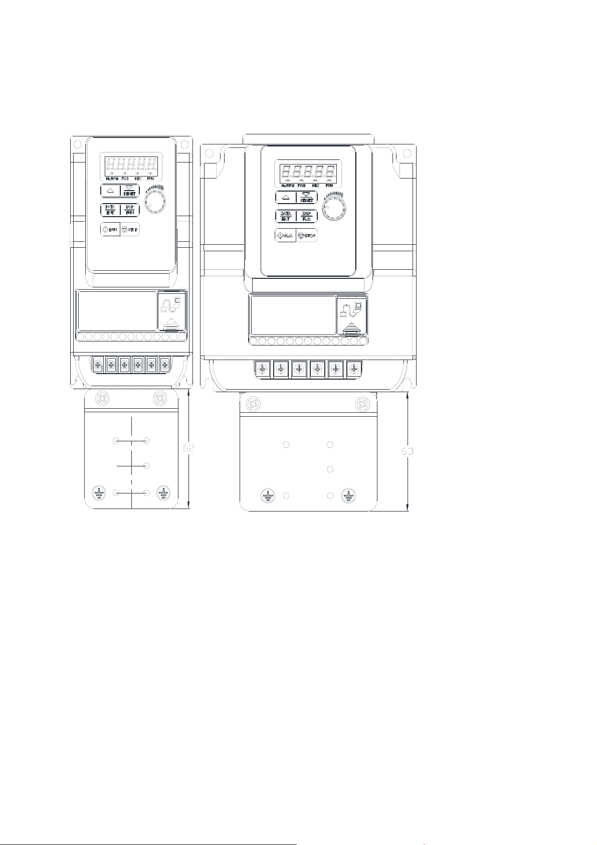
3.7 Outline Dimensions(unit: mm)
Tolerance Table
0~6±0.8 6~30±1.5 30~120±2.5 120~315±4.0 315~1000±6.0
Frame1
H2
W1
W2
W
2-Q1
2-Q2
H1
D2
H
H3
E2
E1
E
D1
Model
L510-1P2-SH1-N/P(P)
L510-1P5-SH1-N/P(P)
L510-2P2-SH1-N/P(P)
L510-2P5-SH1-N/P(P)
L510-201-SH1-N/P(P)
L510-2P2-SH1F-P(P)
L510-2P5-SH1F-P(P)
L510-2P7-SH1F-P(P)
L510-201-SH1F-P(P)
L510-2P2-SH3-N/P(P)
L510-2P5-SH3-N/P(P)
L510-201-SH3-N/P(P)
F : Built-in EMC filter
D
dimension
W W1 W2 H H1 H2 H3 D D1 D2 E E1 E2 Q1 Q2
72 63 61 141 122 131 114 141 136 128.2 86.3 81.1 55 4.4 2.2
3-31
Page 41

Frame2 100V/200V
W1
2-Q1
D2
H2
D1
W2
W
2-Q2
D
H1
H3
H
E2
E1
E
Model
L510-101-SH1-N/P(P)
L510-202-SH1-N/P(P)
L510-203-SH1-N/P(P)
L510-202-SH1F-P(P)
L510-203-SH1F-P(P)
L510-202-SH3-N/P(P)
L510-203-SH3-N/P(P)
F : Built-in EMC filter
W W1 W2 H H1 H2 H3 D D1 D2 E E1 E2 Q1 Q2
118 108 108 144 121 131 114 150 144.2 136.4 101.32 96.73 51.5 4.4 2.2
dimension
3-32
Page 42

Frame2 400V
H2
W1
W2
W
2-Q1
2-Q2
H1
D2
H3
H
E2
E1
E
D1
Model
W W1 W2 H H1 H2 H3 D D1 D2 E E1 E2 Q1 Q2
L510-401-SH3-N/P(P)
L510-402-SH3-N/P(P)
L510-403-SH3-N/P(P)
118 108 108 144 121 131 114 150 144.2 136.4 101.32 96.73 51.5 4.3 2.2
L510-401-SH3F-P(P)
L510-402-SH3F-P(P)
L510-403-SH3F-P(P)
F : Built-in EMC filter
D
dimension
3-33
Page 43

Frame3
W1
D2
2-Q
H2
D1
W
D
H1
H3
H
E2
E1
E
Model
L510-205-SH3(P)
L510-405-SH3(P)
L510-408-SH3(P)
L510-405-SH3F(P)
L510-408-SH3F(P)
dimension
W W1 H H1 H2 H3 D D1 D2 E E1 E2 Q
129 118 197.5 177.6 188 154.7 148 143.7 136 102.6 96 48.2 4.5
3-34
Page 44

Frame4
H2
W1
2-Q
H1
D2
H3
H
D1
Model
L510-208-SH3(P)
L510-210-SH3(P)
L510-410-SH3(P)
L510-415-SH3(P)
L510-410-SH3F(P)
L510-415-SH3F(P)
W
D
E1
E
dimension
W W1 H H1 H2 H3 D D1 D2 E E1 Q
187 176 273 249.8 261 228.6 190 185.6 177.9 136 84.7 4.5
3-35
Page 45

3.8 EMC Filter Disconnection
EMC filter may be disconnected:
Inverter drives with built-in EMC filter are not suitable for connection to certain type of
supply systems, such as listed below; in these cases the RFI filter can be disabled.
In all such cases consult your local electrical standards requirements.
IT type supply systems (ungrounded) & certain supply systems for medical
equipment.
For ungrounded supply systems, if the filter is not disconnected the supply system
becomes connected to Earth through the Y capacitors on the filter circuit. This could
result in danger and damage to the Drive.
Frame1&Frame2
Disconnection steps:
1. Remove EMC filter protection cover by screwdriver.
2. Remove EMC Filter link by pliers.
Note:- Disconnecting the EMC filter link will disables the filter function, please consult your local
EMC standards requirement..
① ②
Frame 3/ Frame 4
Disconnection steps:
1. Loosen the screws for EMC filter
by screwdriver
2. Remove EMC filter
3. Tighten the screw
4. Note:- Disconnecting the EMC filter link will disables the filter function, please consult your local
EMC standards requirement..
① ② ③
3-36
Page 46

Chapter4 Software Index
4.1 Keypad Description
4.1.1 Operator Panel Functions
Type Item Function
Frequency Display, Parameter, voltage, Current,
Temperature, Fault messages.
Hz/RPM: ON when the frequency or line speed is displayed.
OFF when the parameters are displayed.
FWD: ON while the inverter is running forward. Flashes
while stopped.
REV: ON while the inverter is running reverse. Flashes
while stopped.
FUN: ON when the parameters are displayed. OFF when
the frequency is displayed.
STOP: Decelerate or Coast to Stop.
RESET: Use to Reset alarms or resettable faults.
Increment parameter number and preset values.
Decrement parameter number and preset values.
“<” Left Shift:
Used while changing the parameters or parameter values
ENTER:
Used to display the preset value of parameters and for saving
the changed parameter values.
Digital
display &
LEDs
Variable
Resistor
Keys
On Keypad
Main digital displays
LED Status
FREQ SET Used to set the frequency
RUN RUN: Run at the set frequency.
STOP/RESET
(Dual function keys)
▲
▼
MODE Switch between available displays
</ENTER
(Dual function keys,
a short press for left
shift function, a long
press for ENTER
function)
4-1
Page 47

4.1.2 Digital display Description
Alpha numerical display format
Digit
0
1
LED
Letter
A n
b o
LED
Letter
LED
Symbol
-
°
LED
2
3
4
5
6
7
8
9
C P _
d q
E r
F S
G t
H u
J V
L Y
.
Digital display indication formats
Actual output frequency Set frequency
Digits are lit Continually Preset digits flashing Selected digit flashing
4-2
Page 48

LED display examples
Display
Description
In stop mode shows the set frequency
In run mode shows the actual output frequency
Selected Parameter
Parameter Value
Output Voltage
Output Current in Amps
DC Bus voltage
Temperature
PID feedback value
Error display
Analogue Current / Voltage ACID / AVI . Range ( 0~1000)
LED Status description
LED Indicator light Status
Frequency / line
speed Indicator
Menu mode indicator
Hz/RPM
Hz/RPM
Fun
FUN
On
On while not displaying frequency or line speed
FWD indicator
FWD
FWD
On while running
forward
FWD
FWD
Flashing while
stopped in
Forward mode.
REV indicator light
On while running
REV
REV
reverse
4-3
REV
REV
Flashing while
stopped in
Reverse mode
Page 49

4.1.3 Digital display setup
On power up digital display screens will be as shown below.
MODE
MODE
parameter
Power supply
2sec later
frequency
User selectable display formats:
12- 00 Display Mode
0 0 0 0 0
high
Low
Each of the above 5 digits can be set to any of the selections below from 0 to 7
Range
The highest bit of 12-00 sets the power on the display, other bits set the selected display from range
0-7.as Listed above.
Example1: Set parameter 12- 00=【10000】to obtain display format shown below.
【0】:Disable display 【1】:output Current
【2】:output Voltage 【3】:DC voltage
【4】:Temperature 【5】:PID feedback
【6】:AVI 【7】:ACI
display:Power supply
2sec later
Output Current
MODE
parameter
MODE MODE
Set frequency
4-4
Page 50

Example 2. Set parameter 2: 12- 00=【12345】 to obtain the display format shown below.
MODE
Temperature
< 4 >
PIDfeedback
< 5 >
2sec later
Display: Power supply
Output Current
< 1 >
Increment/ Decrement key functions:
MODE
MODE
MODE
Set Frequency
MODE
MODE
MODE
DC voltage
< 3 >
Output Voltage
< 2 >
Parameter
1.“
▲”/ “▼” :
T1
Short time press
Long time press
T2
Quick pressing of these keys will Increment or Decrement the selected digit by one.
Extended pressing will Increment or Decrement the selected digit continuously.
2.“</ENT” Key functions :
“</ENT”
short press for left shift
function
“</ENT”
long press for ENT
function
T1
T2
Quick pressing of this key will display the preset value of the parameter selected.
Extended pressing of this key will save the altered value of the selected parameter.
4-5
Page 51

4.1.4 Example of keypad operation
Example1: Modifying Parameters
Frequency
Short press
MODE once
Short press
</ENT once
Short press
</ENT twice
Long press
</ENT once
Short press
once
▲
Long press
</ENT once
Short press
once
▲
4-6
Page 52

Example2: Modifying the frequency from keypad in run and stop modes.
A
A
A
Modify frequency is stopping
Modify frequency in stopping
Power Supply
Power supply Power supply
2sec later
2sec later 2sec later
Modify frequency is stopping
Modify frequency in operating
Power supply
2sec later
Set frequency display
Set frequency display Set frequency display
Short press
Short time press
</ENT once
</ENT once
Modify bit<unit>
Short time press
Short press
</ENT once
</ENT once
Short press
Short time press
</ENT once
</ENT once
Modify bit<unit>
Modify bit<ten>
Modify bit<ten>
Set frequency display
Press run
Press RUN
Actual frequency
ctual frequency
Short time press
Short press
</ENT once
</ENT once
Modify bit<unit>
Short time press
Short press
</ENT once
</ENT once
Modify bit<ten>
Short time press
Short press
</ENT once
</ENT once
Modify bit<unit>
Modify bit<ten>
Without
pressing the
Without pressing
button
the button </ENT,
</ENT,
fter 5 seconds to
After 5
return
seconds to
return
Short time press
Short press
▲once
▲ once
5sec later
5 sec later or
or long time press
long press
</ENT once
</ENT once
Modify bit<hundred>
Modify bit<hundred+1>
Modify bit<hundred+1>
Short time press
Short press
▲once
▲ once
Long time press
Long press
</ENT once
</ENT once
Modify bit<hundred>
Modify bit<hundred>
Modify bit<hundred+1>
Modify bit<hundred+1>
Actual frequency
ctual frequency
Modify bit<hundred>
Note: frequency command setting will be limited to the range set by parameters for lower &
upper frequency.
4-7
Page 53

4.1.5 Operation Control
A
Stop Stop
Run
ctual
output
frequency
Stop FWDREVRun FWD REV Power
FWD
LED
REV
LED
FWD FWDFWDFWDFWD FWD FWD
REVREVREVREVREV REV REV
4-8
Page 54

4.2 Programmable Parameter Groups
Parameter Group No. Description
Grou p 00 Basic parameters
Grou p 01 V/F Pattern selections & setup
Grou p 02 Motor parameters
Grou p 03 Multi function digital Inputs/Outputs
Grou p 04 Analog signal inputs/ Analog output
Grou p 05 Preset Frequency Selections.
Grou p 06 Auto Run(Auto Sequencer) function
Grou p 07 Start/Stop command setup
Grou p 08 Drive and motor Protection
Grou p 09 Communication function setup
Gr ou p 10 PI D function setup
Grou p 11 Performance control functions
Group 12 Digital Display & Monitor functions
Grou p 13 Inspection & Maintenance function
Grou p 14 PUMP Application Function
Parameter notes for Parameter Groups
Parameter can be adjusted during running mode Notes1: Revised in version 05.
*1
Cannot be modified in communication mode
*2
Does not change with factory reset
*3
Read only
*4
4-9
Page 55

Grou p 00- The basic parameters group
No. Description Range
00-00
00-01
00-02
00-03
00-04
00-05
control mode
Motor rotation
Main Run
Source Selection
Alternative Run
Source Selection
Operation modes for
external terminals
Main Frequency
Source Selection
0:V/F mode
1:SLV mode
0:Forward
1:Reverse
0:Keypad
1:External Run/Stop Control
2:Communication
0:Keypad
1:External Run/Stop Control
2:Communication
0: Forward/Stop-Reverse/Stop
1: Run/Stop-Reverse/Forward
2: 3-Wire Control Mode-Run/Stop
0:Keypad
1:Potentiometer on Keypad
2:External AVI Analog Signal Input
3:External ACI Analog Signal Input
4:External Up/Down Frequency
Control
5:Communication setting Frequency
6:PID output frequency
Factory
Setting
0
0 - *1
1 -
0 -
0 -
2 -
Unit Note
-
00-06
00-07
00-08
00-09
00-10
00-11
00-12
00-13
00-14
00-15
00-16
00-17
00-18
00-19
00-20
0:Keypad
1:Potentiometer on Keypad
Alternative Frequency
Source Selection
Main and Alternative
Frequency Command modes
Communication
Frequency Command
Frequency command
Save mode
(Communication mode)
Initial Frequency
Selection ( keypad mode)
Initial Frequency
Keypad mode
Frequency Upper Limit 0.01~599.00 50.00/60.00 Hz
Frequency Lower Limit 0.00~598.99 0.00 Hz
Acceleration Time 1 0.1~3600.0
Deceleration Time 1 0.1~3600.0
Acceleration Time 2 0.1~3600.0
Deceleration Time 2 0.1~3600.0 10.0 s *1
Jog Frequency 1.00~25.00 2.00 Hz *1
Jog Acceleration Time 0.1~25.5
Jog Deceleration Time 0.1~25.5
2:External AVI Analog Signal Input
3:External ACI Analog Signal Input
4:External Up/Down Frequency
Control
5:Communication setting Frequency
6:PID output frequency.
0: Main Or Alternative Frequency
1: Main frequency+Alternative
Frequency
0.00~599.00 Hz *4
0:Save the frequency before power
down
1:Save the communication frequency
0:by Current Frequency Command
1:by 0 Frequency Command
2:by 00-11
0.00~599.00 50.00/60.00 Hz
0 -
0 -
0 -
0 -
10.0
10.0
10.0
0.5
0.5
s
s
s
s
s
*1
*1
*1
*1
*1
4-10
Page 56

Group 01- V/F Pattern selection & Setup
No. Description Range
01-00
01-01
01-02
01-03
01-04
01-05
01-06
01-07
01-08
01-09
01-10
01-11
01-12
01-13
01-14
01-15
01-16
01-17
01-18
Volts/Hz Patterns 1~7 1/4 -
V/F Max voltage
Max Frequency 0.2 ~ 599.00 50.00/60.00 Hz
Max Frequency Voltage Ratio 0.0 ~ 100.0 100.0 %
Mid Frequency 2 0.1 ~ 599.00 2.50/3.00 Hz
Mid Frequency Voltage Ratio 2 0.0 ~ 100.0 10.0/6.8 %
Mid Frequency 1 0.1 ~ 599.00 2.50/3.00 Hz
Mid Frequency Voltage Ratio 1 0.0 ~ 100.0 10.0/6.8 %
Min Frequency 0.1 ~ 599.00 1.30/1.50 Hz
Min Frequency Voltage Ratio 0.0 ~ 100.0 8.0/3.4 %
Volts/Hz Curve Modification
(Torque Boost)
V/F start Frequency 0.00~10.00 0.00 Hz
No-load oscillation suppression
gain
Motor Hunting Prevention
Coefficient
Motor Hunting Prevention Gain 0~100
Motor Hunting Prevention Limit 0~100.0 5.0 %
Auto-Torque Compensation
Filter Coefficient 0.1~1000.0
Auto-torque Compensation
Gain
Auto-torque Compensation
Frequency
200V:170.0~264.0
400V:323.0~528.0
0 ~ 10.0 0.0 % *1
0.0~200.0 0 %
1~8192 800
0~100 0 %
1.30~5.00 2 Hz
Factory
Setting
Based on 13-08 Vac
Frame1/2 100V/200V
series: 7
others: 0
0.1 ms
Unit Note
%
4-11
Page 57

Grou p 02- Motor parameters
No. Description Range
02-00
02-01
02-02 V/F Slip Compensation
02-03
02-04
02-05
02-06
02-07
02-08
02-09
02-10
02-11
02-12
02-13
02-14
02-15
02-16
02-17
02-18
02-19
Motor No Load Current
Motor Rated Current (OL1) ---- by motor nameplate A *4
Motor Rated Speed
Motor Rated Voltage ---- by motor nameplate Vac
Motor Rated Power 0~22.0 by motor nameplate kW
Motor Rated Frequency 0~599.0 by motor nameplate
Motor Auto Tuning
Stator Resistor Gain 0~600
Rotor Resistor Gain 0~600
Reserved
Reserved
Reserved
SLV Slip Compensation Gain 0~200 by series %
SLV Torque Compensation
Gain
Low Frequency Torque Gain 0~100 50 %
SLV Without Load Slip
Compensation Gain
SLV With Load Slip
Compensation Gain
SLV With Load Torque
Compensation Gain
SLV Slip Compensation Select
----
0.0 ~ 100.0 0.0 % *1
----
0: Disable
1: Static auto tuning
0~200 100 %
0~200 by series %
0~200 150 %
0~200 100 %
0: Slip Compensation 1
2: Slip Compensation 2
4-12
Factory
Setting
by motor nameplate A
by motor nameplate Rpm
0
by series
by series
0
Unit Note
*4
*4
*4
Page 58

Group 03- Multi function Digital Inputs/Outputs
No. Description Range
03-00
03-01
03-02
03-03
03-04
03-05
03-06
03-07
03-08
03-09
03-10
03-11
03-12
03-13
Multifunction Input Term. S1 0: Forward/Stop Command
Multifunction Input Term. S2
Multifunction Input Term. S3
Multifunction Input Term. S4
Multifunction Input Term. S5
Up/Down frequency band 0.00~5.00 0.00 Hz
Up/Down Frequency modes
S1~S5 scan confirmation 1~200. Number of Scan cycles 10 2ms
S1~ S5 switch type select
Output Relay(RY1)
Output frequency detection
1: Reverse/Stop Command
2: Preset Speed 1 (5-02)
3: Preset Speed 2 (5-03)
4: Preset Speed 4 (5-05)
6: Jog Forward Command
7: Jog Reverse Command
8: Up Command
9: Down Command
10: Acc/Dec 2
11: Acc/Dec Disabled
12: Main/Alternative Run Command select
13: Main/Alternative Frequency Command
select
14: Rapid Stop ( Decel to stop)
15: Base Block
16: Disable PID Function
17: Reset
18: Auto Run Mode enable
19: Forced Frequency Run(pump model only)
20: Switch to Constant Pressure 2(pump
model only)
Reserved
0: Preset frequency is held as the inverter
stops, and UP/Down function is disabled.
1: Preset frequency is reset to 0 Hz as the
inverter stops.
2: Preset frequency is held as the inverter
stops, and the UP/Down is available.
xxxx0:S1 NO xxxx1:S1 NC
xxx0x:S2 NO xxx1x:S2 NC
xx0xx:S3 NO xx1xx:S3 NC
x0xxx:S4 NO x1xxx:S4 NC
0xxxx:S5 NO 1xxxx:S5 NC
Reserved
0: Run
1: Fault
2: Setting Frequency Reached
3: Frequency Reached (3-13±3-14)
4: Output Frequency Detection1(> 3-13)
5: Output Frequency Detection2(< 3-13)
6: Auto-Restart
7: Momentary AC Power Loss
8: Rapid Stop
9: Base Block
10: Motor Overload Protection(OL1)
11: Drive Overload Protection(OL2)
12: Reserved
13: Output Current Reached
14: Brake Control
15: PID feedback disconnection detection
16: High Pressure Detection
17: Low Pressure Detection
18: Pressure Loss Detection
Reserved
0.00~599.00 0.00 Hz *1
Factory
Setting
0
1
2 -
3 -
17 - Note1
0 -
00000 -
1 -
Unit Note
-
-
Note1
4-13
Page 59

Group 03- Multi function Digital Inputs/Outputs
No. Description Range
level (Hz)
03-14
03-15
03-16
03-17
03-18
03-19
03-20
03-21
※ “NO” indicates normally open, “NC” indicates normally closed.
Frequency Detection band
Output Current Detection
Level
Output Current Detection
Period
External Brake Release
level
External Brake Engage
Level
Relay Output function type
Braking Transistor On Level
Brake Transistor Off Level
0.00~30.00 2.00 Hz *1
0.1~999.9 0.1 A
0.1~10.0 0.1 s
0.00~20.00 0.00 Hz
0.00~20.00 0.00 Hz
0:A (Normally open)
1:B (Normally close)
100/200V:
240.0~400.0V
400V: 500.0~800.0V
100/200V:
240.0~400.0V
400V: 500.0~800.0V
220/230V:
380/400V:
415/460V:
220/230V:
380/400V:
415/460V:
Factory
Setting
0 -
380
690
780
360
650
740
Unit Note
VDC
VDC
4-14
Page 60

Group 04- Analog signal inputs/ Analogue output functions
No. Description Range
ACI
04-00
04-01
04-02
04-03
04-04
04-05
04-06
04-07
04-08
04-09
04-10
04-11
04-12
04-13
04-14
04-15
04-16
04-17
04-18
04-19
AVI/ACI analog Input
signal type select
AVI Signal Verification
Scan rate
AVI Gain 0~1000 100 % *1
AVI Bias 0~100 0 % *1
AVI Bias Selection 0: Positive 1: Negative 0 - *1
AVI Slope 0: Positive 1: Negative 0 - *1
ACI Signal Verification
Scan rate
ACI Gain 0~1000 100 % *1
ACIBias 0~100 0 % *1
ACI Bias Selection 0: Positive 1: Negative 0 - *1
ACI Slope 0: Positive 1: Negative 0 - *1
Analog Output mode
(AO)
Analog Output AO Gain
(%)
Analog Output AO Bias
(%)
AO Bias Selection
AO Slope
Potentiometer Gain on
Keypad
Potentiometer Bias on
Keypad
Potentiometer Bias
Selection on Keypad
Potentiometer Slop on
Keypad
0:
1:
2:
3:
1~200 50 2ms
1~200 50 2ms
0: Output Frequency
1: Frequency Command
2: Output Voltage
3: DC Bus Voltage
4: Motor Current
0~1000 100 % *1
0~1000 0 % *1
0: Positive
1: Negative
0: Positive
1: Negative
0~1000 100 % *1
0~100 0 % *1
0: Positive
1: Negative
0: Positive
1: Negative
0~10V 0~20mA
0~10V 4~20mA
2~10V 0~20mA
2~10V 4~20mA
AVI
Factory
Setting
0 -
0 - *1
0 - *1
0 - *1
0 - *1
0 - *1
Unit Note
4-15
Page 61

Group 05- Preset Frequency Selections.
No. Description Range
0: Common Accel/Decel Accel/Decel 1
or 2 apply to all speeds
1: Individual Accel/Decel Accel/ Decel
0-7 apply to the selected preset
speeds (Acc0/Dec0~ Acc7/Dec7)
0.00 ~ 599.00
0.00 ~ 599.00
0.00 ~ 599.00
0.00 ~ 599.00
0.00 ~ 599.00
0.00 ~ 599.00
0.00 ~ 599.00
0.00 ~ 599.00
0.1 ~ 3600.0
0.1 ~ 3600.0
0.1 ~ 3600.0
0.1 ~ 3600.0
0.1 ~ 3600.0
0.1 ~ 3600.0
0.1 ~ 3600.0
0.1 ~ 3600.0
0.1 ~ 3600.0
0.1 ~ 3600.0
0.1 ~ 3600.0
0.1 ~ 3600.0
0.1 ~ 3600.0
0.1 ~ 3600.0
0.1 ~ 3600.0
0.1 ~ 3600.0
Reserved
05-00
05-01
05-02
05-03
05-04
05-05
05-06
05-07
05-08
05-09
~
05-16
05-17
05-18
05-19
05-20
05-21
05-22
05-23
05-24
05-25
05-26
05-27
05-28
05-29
05-30
05-31
05-32
Preset Speed Control
mode Selection
Preset Speed 0
(Keypad Freq)
Preset Speed1
Preset Speed2
Preset Speed3
Preset Speed4
Preset Speed5
Preset Speed6
Preset Speed7
Preset Speed0-Acctime
Preset Speed0-Dectime
Preset Speed1-Acctime
Preset Speed1-Dectime
Preset Speed2-Acctime
Preset Speed2-Dectime
Preset Speed3-Acctime
Preset Speed3-Dectime
Preset Speed4-Acctime
Preset Speed4-Dectime
Preset Speed5-Acctime
Preset Speed5-Dectime
Preset Speed6-Acctime
Preset Speed6-Dectime
Preset Speed7-Acctime
Preset Speed7-Dectime
Factory
Setting
0 -
5.00 Hz *1
5.00 Hz *1
10.00 Hz *1
20.00 Hz *1
30.00 Hz *1
40.00 Hz *1
50.00 Hz *1
50.00 Hz *1
10.0 s *1
10.0
10.0
10.0
10.0
10.0
10.0
10.0
10.0
10.0
10.0
10.0
10.0
10.0
10.0
10.0
Unit Note
s
s
s
s
s
s
s
s
s
s
s
s
s
s
s
*1
*1
*1
*1
*1
*1
*1
*1
*1
*1
*1
*1
*1
*1
*1
4-16
Page 62

Group 06- Auto Run(Auto Sequencer) function
No. Description Range
0: Disabled.
1: Single cycle.
(Continues to run from the Unfinished
step if restarted).
2: Periodic cycle.
(Continues to run from the unfinished
step if restarted).
3: Single cycle, then holds the speed Of
final step to run.
(Continues to run from the unfinished
step if restarted).
4: Single cycle.
(Starts a new cycle if restarted).
5: Periodic cycle.
(Starts a new cycle if restarted).
6: Single cycle, then hold the speed of
final step to run
(Starts a new cycle if restarted).
0.00~599.00
0.00~599.00
0.00~599.00
0.00~599.00
0.00~599.00
0.00~599.00
0.00~599.00
0.0 ~ 3600.0
0.0 ~ 3600.0
0.0 ~ 3600.0
0.0 ~ 3600.0
0.0 ~ 3600.0
0.0 ~ 3600.0
0.0 ~ 3600.0
0.0 ~ 3600.0
0: Stop 1: Forward 2: Reverse
0: Stop 1: Forward 2: Reverse
Reserved
Reserved
06-00
06-01
06-02
06-03
06-04
06-05
06-06
06-07
06-08
~
06-15
06-16
06-17
06-18
06-19
06-20
06-21
06-22
06-23
06-24
~
06-31
06-32
06-33
Auto Run
(sequencer)
mode selection
Auto _ Run Mode
frequency command 1
Auto _ Run Mode
frequency command 2
Auto _ Run Mode
frequency command 3
Auto _ Run Mode
frequency command 4
Auto _ Run Mode
frequency command 5
Auto _ Run Mode
frequency command 6
Auto _ Run Mode
frequency command 7
Auto_ Run Mode
running time setting 0
Auto_ Run Mode
running time setting 1
Auto_ Run Mode
running time setting 2
Auto_ Run Mode
running time setting 3
Auto_ Run Mode
running time setting 4
Auto_ Run Mode
running time setting 5
Auto_ Run Mode
running time setting 6
Auto_ Run Mode
running time setting 7
Auto_ Run Mode
running direction 0
Auto_ Run Mode
running direction 1
Factory
Setting
0 -
0.00 Hz *1
0.00 Hz *1
0.00 Hz *1
0.00 Hz *1
0.00 Hz *1
0.00 Hz *1
0.00 Hz *1
0.0 s *1
0.0 s *1
0.0 s *1
0.0 s *1
0.0 s *1
0.0 s *1
0.0 s *1
0.0 s *1
0 -
0 -
Unit Note
4-17
Page 63

Group 06- Auto Run(Auto Sequencer) function
No. Description Range
06-34
06-35
06-36
06-37
06-38
06-39
Auto_ Run Mode
running direction 2
Auto_ Run Mode
running direction 3
Auto_ Run Mode
running direction 4
Auto_ Run Mode
running direction 5
Auto_ Run Mode
running direction 6
Auto_ Run Mode
running direction 7
0: Stop 1: Forward 2: Reverse
0: Stop 1: Forward 2: Reverse
0: Stop 1: Forward 2: Reverse
0: Stop 1: Forward 2: Reverse
0: Stop 1: Forward 2: Reverse
0: Stop 1: Forward 2: Reverse
Factory
Setting
0 -
0 -
0 -
0 -
0 -
0 -
Unit Note
4-18
Page 64

Group 07- Start/Stop command setup
No. Description Range
07-00
07-01
07-02
07-03
07-04
07-05
07-06
07-07
07-08
07-09
07-10
07-11
Momentary Power
Loss and Restart
Auto Restart Delay
Time
Number of Auto
Restart Attempts
Reset Mode Setting
Direct Running After
Power Up
Delay-ON Timer 1.0~300.0
DC Injection Brake
Start Frequency (Hz)
In Stop mode
DC Injection Brake
Level (%) In stop
mode
DC Injection Brake
Time (Seconds)
In stop mode
Stopping Method
DC Braking Level at
Start
DC Braking Time at
Start
0: Momentary Power Loss and Restart disable
1: Momentary power loss and restart enable
0.0~800.0
0~10
0: Enable Reset Only when Run Command is Off
1: Enable Reset when Run Command is On or Off
0: Enable Direct run on power up
1: Disable Direct run on power up
0.10 ~ 10.00
0 ~ 20 (Frame1/2). Based on the 20% of maximum
output voltage
0 ~ 100 (Frame3/4) based on the rated current
0.0 ~ 25.5
0: Deceleration to stop
1: Coast to stop
0~100
0.0~25.5
Factory
Setting
0 s
0.0 s
0 -
0 -
1 -
1.0 s
1.5 Hz
5
50
0.5 s
0
0 %
0.0 s
Unit Note
%
4-19
Page 65

Group 08- Drive & Motor Protection functions
No. Description Range
xxxx0: Enable Trip Prevention During
Acceleration
xxxx1: Disable Trip Prevention During
Acceleration
xxx0x: Enable Trip Prevention During
Deceleration
xxx1x: Disable Trip Prevention During
08-00
08-01
08-02
08-03
08-04
08-05
08-06
08-07
08-08
08-09
08-10
Trip Prevention Selection
Trip Prevention Level
During Acceleration (%)
Trip Prevention Level
During Deceleration (%)
Trip Prevention Level In
Run Mode (%)
over voltage Prevention
Level in Run Mode
Electronic Motor
Overload Protection
Operation Mode
Operation After
Overload Protection is
Activated
Over heat Protection
(cooling fan control)
AVR Function
(Auto Voltage
Regulation)
Input phase lost
protection
PTC Overheat Function
xx0xx: Enable Trip Prevention in Run
xx1xx: Disable Trip Prevention in Run
x0xxx: Enable over voltage Prevention
x1xxx: Disable over voltage Prevention
50 ~ 200 by series
50 ~ 200 by series
50 ~ 200 by series
200V: 350.0~390.0
400V: 700.0~780.0
xxxx0: Disable Electronic Motor
xxxx1: Enable Electronic Motor
xxx0x: Motor Overload Cold Start
xxx1x: Motor Overload Hot Start
xx0xx: Standard Motor
xx1xx: Invertor Duty Motor
0: Coast-to-Stop After Overload
1: Drive Will Not Trip when Overload
0: Auto (Depends on temp.)
1: Operate while in RUN mode
2: Always Run
3: Disabled
0: AVR function enable
1: AVR function Disable
2: AVR function disable for stop
3: AVR function disable for deceleration
4: AVR function disable for stop and
deceleration.
5: When VDC>(360V/740V), AVR
0: Disabled
1: Enabled
0: Disable
1: Decelerate to stop
2: Coast to stop
3: Continue running, when warning
Deceleration
Mode
Mode
in Run Mode
in Run Mode
Overload Protection
Overload Protection
Protection is Activated
Protection is Activated (OL1)
function disable for stop and
deceleration.
level is reached. Coast to stop, when
protection level is reached.
Factory
Setting
00000 -
380.0/760.0 VDC *1
00001 -
0 -
1 -
4 -
0 -
0
Unit Note
Inverter
Rated
Current
100%
4-20
Page 66

Group 08- Drive & Motor Protection functions
No. Description Range
08-11
08-12
PTC Signal Smoothing
Time
PTC Detection Time
Delay
0.01~10.00 0.2 Sec
1~300 60 Sec
Factory
Setting
Unit Note
08-13
08-14
08-15
08-16
08-17
08-18
08-19
PTC Protection Level 0.1~10.0 0.7 V
PTC Detection Level
Reset
PTC Warning Level 0.1~10.0 0.5 V
Fan Control Temperature
Level
Over current protection
level
Over current protection
time
Motor Overload
Protection Level
0.1~10.0 0.3 V
10.0~50.0 50.0 °C
0.0 ~ 60.0 0.0 A
0.0 ~ 1500.0 1.0 s
0: Motor Overload Protection Level 0
1: Motor Overload Protection Level 1
2: Motor Overload Protection Level 2
0
4-21
Page 67

Group 09- Communication function setup
No. Description Range
09-00
09-01
09-02
09-03
09-04
09-05
09-06
09-07
09-08
09-09
09-10
Assigned Communication
Station Number
Communication Mode Select
Baud Rate Setting (bps)
Stop Bit Selection
Parity Selection
Data Format Selection
Communication time-out
detection time
Communication time-out
operation selection
Error 6 verification time. 0 ~ 20
Drive Transmit delay Time(ms) 5 ~ 65
BACnet stations
1 ~ 32 1 - *2*3
0: Modbus RTU code
1: Modbus ASCII code
2: BACnet (Pump application built-in
without this function)
0: 4800
1: 9600
2: 19200
3: 38400
0: 1 Stop Bit
1: 2 Stop Bits
0: Without Parity
1: With Even Parity
2: With Odd Parity
0: 8-Bits Data
1: 7-Bits Data
0.0 ~ 25.5
0: Deceleration to stop (set by 00-15)
1: Coast to stop
2: Deceleration to stop (set by 00-17)
3: continue operating
1~254(Pump application built-in
without this function)
Factory
Setting
0 -
2 bps *2*3
0 - *2*3
0 - *2*3
0 - *2*3
0.0 s
0 -
3
5 2ms
1
Unit Note
*2*3
Note1
*2*3
Note1
4-22
Page 68

Group10- PID function Setup
No. Description Range
0:Potentiometer on Keypad
1: Analog Signal Input. (AVI)
2: Analog Signal Input. (ACI)
3: Frequency set by communication
4: 10-02 given
5: Preset frequency
0: Potentiometer on Keypad
1: Analog Signal Input. (AVI)
2: Analog Signal Input. (ACI)
3: Communication Setting Frequency
10-00
10-01
PID target value selection
(when 00-05\00-06=6
,this function is enabled)
PID feedback value selection
Factory
Setting
1 - *1
2 - *1
Unit Note
10-02
10-03
10-04
10-05
10-06
10-07
10-08
10-09
10-10
10-11
10-12 Feedback Loss Detection Level
10-13
10-14
10-15
10-16
10-17 PID Sleep Frequency Level
10-18
10-19 PID Wake up frequency Level
10-20
10-21
10-22
PID Target (keypad input)
PID Mode Selection
Feedback Gain Coefficient
Proportional Gain
Integral Time
Derivative Time
PID Offset
PID Offset Adjust
PID Output Lag Filter Time
Feedback Loss Detection
Mode
Feedback Loss Detection
Delay Time
Integration Limit Value
Integral Value Resets to Zero
when Feedback Signal Equals
the Target Value
Allowable Integration Error.
Margin (units)(1unit = 1/8192)
PID Sleep Function Delay Time
PID Wake up function Delay
Time
Max PID Feedback Setting
Min PID Feedback Setting 0 ~999 0 - *1
0.0~100.0 50.0 % *1
0: Disabled.
1: Deviation D Control. FWD Characteristic.
2: Feedback D Control. FWD Characteristic
3: Deviation D Control. Reverse Characteristic.
4: Feedback D Control. Reverse Characteristic
5: Frequency Command + Deviation D Control.
FWD Characteristic
6: Frequency Command + Feedback D Control
FWD Characteristic.
7: Frequency Command + Deviation D Control
Reverse Characteristic.
8: Frequency Command + Feedback D Control
Reverse Characteristic
0.00 ~ 10.00 1.00 % *1
0.0 ~ 10.0 1.0 % *1
0.0 ~ 100.0 10.0 s *1
0.00 ~ 10.00 0.00 s *1
0: Positive
1: Negative
0 ~ 109 0 % *1
0.0 ~ 2.5 0.0 s *1
0: Disabled
1: Drive keeps running after feedback loss
2: Drive stops after feedback loss
0 ~ 100
0.0 ~25.5
0 ~ 109 100 % *1
0: Disabled
1: 1 Second
30: 30 Seconds (0 ~ 30)
0 ~ 100 0 -
0.00~599.00
0.0 ~25.5 0.0 s
0.00 ~ 599.00
0.0 ~ 25.5
0 ~999
0 -
0 - *1
0 -
0 %
1.0 s
0 -
0.00 Hz
0.00 Hz
0.0 s
100 - *1
4-23
Page 69

Group11- Performance Control functions
No. Description Range
11-00
11-01
11-02
11-03
11-04
11-05
11-06
11-07
11-08
11-09
11-10
11-11
11-12
11-13
11-14
11-15
11-16
11-17
11-18
11-19
11-20
11-21
Reverse operation control
Carrier Frequency (kHz) 1~16 5 KHz
Carrier mode Selection
Carrier Frequency
Reduction by temperature rise
S-Curve Acc 1 0.0 ~ 4.0 0.00 s
S-Curve Acc 2 0.0 ~ 4.0 0.00 s
S-Curve Dec 3 0.0 ~ 4.0 0.00 s
S-Curve Dec 4 0.0 ~ 4.0 0.00 s
Skip Frequency 1 0.00 ~ 599.00 0.00 Hz *1
Skip Frequency 2
Skip Frequency 3
Skip Frequency Bandwidth (±) 0.00 ~ 30.00 0.00 Hz *1
Regeneration Prevention
Function
Regeneration Prevention
Voltage Level
Regeneration Prevention
Frequency Limit
Regeneration Prevention
Voltage Gain
Regeneration Prevention
Frequency Gain
Speed loop proportion gain
Speed loop integration gain
Speed loop differential gain
Stop Key Selection
0: Reverse command is valid
1: Reverse command is invalid
0: Mode0, 3phase PWM modulation
1: Mode1, 2phase PWM modulation
2: Mode2, random PWM modulation
0: Disabled
1: Enabled
0.00 ~ 599.00
0.00 ~ 599.00
Reserved
0: Disable
1: Enable
2: Enable (during constant speed only)
200v: 300.0~400.0
400v: 600.0~800.0
0.00~15.00 3.00 Hz
0~200 100 %
0~200 100 %
0~65535 10000
0 ~65535 800
0 ~65535 0
0: Enable Stop Key when Run Command
not from Keypad
1: Disable Stop Key when Run Command
not from Keypad
Factory
Setting
0 -
1 -
0 -
0.00 Hz *1
0.00 Hz *1
0 -
380/760 V
0
unit Note
4-24
Page 70

Group12 Digital Display & Monitor functions
No. Description Range
00000 ~77777.
Each digit can be set to 0 to 7
0: Default display(frequency¶meters)
1:Output Current
12-00
12-01
12-02
12-03
12-04
Extended Display Mode
PID Feedback Display
format
PID Feedback Display
Unit Setting
Custom Units (Line
Speed) Value
Custom Units (Line
Speed) Display Mode
2:Output Voltage
3:DC voltage
4:Temperature of Heat sink
5:PID feedback
6:Analog Signal Input. (AVI)
7:Analog Signal Input. (ACI)
0: Integer (xxx)
1: One decimal Place (xx.x)
2: Two Decimal Places (x.xx)
0: xxx-1: xxxpb (pressure)
2: xxxfl (flow)
0~65535 1500/1800 RPM *1
0:Drive Output Frequency is Displayed
1:Line Speed. Integer.(xxxxx)
2:Line Speed..One Decimal Place (xxxx.x)
3:Line Speed.Two Decimal Places (xxx.xx)
4:Line Speed.Three Decimal Places (xx.xxx)
S1 S2 S3 S4 S5
Factory
Setting
00321 - *1
0 - *1
0 - *1
0 - *1
Unit Note
12-05
12-06
12-07
Inputs and output
Logic status display
( S1 to S5) & RY1
Output Power
Motor Current
Percentage
----
----
----- - *4
RY1
0.0 kW
0 %
4-25
Page 71

Group 13 Inspection & Maintenance functions
No. Description Range
13-00
13-01
13-02
13-03
13-04
13-05
13-06
Drive Horsepower
Code
Software Version ---- - - *3*4
Fault Log
(Last 3 Faults)
Accumulated
Operation Time1 1
Accumulated
Operation Time1 2
Accumulated
Operation Time Mode
Parameter Lock
---- - - *3
---- - - *3*4
0~23 - hour *3
0~65535 ---- day *3
0: Time Under Power
1: Run Mode Time Only
0: Enable all Functions
1: Preset speeds 05-01~05-08 cannot be
changed
2: All Functions cannot be changed
Except for Preset speeds 05-01~05-08
3: Disable All Function
Factory
Setting
0 - *3
0 -
unit Note
13-07
13-08
Parameter Lock Code 00000~65535 00000 -
1150: Initialization (50Hz,220V/380V)
Restore Factory
Settings
1160: Initialization (60Hz,220V/380V)
1250: Initialization (50Hz,230V/400V)
1260: Initialization (60Hz,230V/460V)
1350: Initialization (50Hz,220V/415V)
1360: Initialization (60Hz,230V/400V)
Notes:
For built-in EMC filter models, the default setting of 13-08 is “1250”.
For without built-in EMC filter models, the default setting of 13-08 is “1360”
1250/1360
(Note)
-
4-26
Page 72

Group 14 PUMP Application Function
No. Description Range
14-00
14-01
14-02
14-03
14-04
14-05
Function Selection
Setting of Single & Multiple
Pumps and Master & Slave
Machines
Operation Pressure Setting 0.1~(the value of 14-03) 4.00 PSI
Maximum Pressure Setting of
Pressure Transmitter
Pump Pressure Command
Source
Display Mode Selection
0: Disable
1: PUMP
0: Single Pump
1: Master
2: Slave 1
3: Slave 2
4: Slave 3
0.10 ~ 650.00
0:Set by 14-02
1:Set by AI
0: Display of Target and Pressure
Feedback (14-03<99)
1: Target Pressure Only
2: Feedback Pressure Only
Factory
Setting
0 - Note1
0 -
10.00 PSI
0 -
0 -
unit
Note
Note1
Note1
Note1
Note1
Note1
14-06
14-07
14-08
14-09
14-10
14-11
14-12
14-13
14-14
14-15
14-16
14-17
14-18
14-19
14-20
14-22
14-23
14-24
Proportion Gain(P) 0.00~10.00
Integral Time(I) 0.0~100.0
Differential Time(D) 0.00~10.00
Tolerance Range of Constant
Pressure
Sleep Frequency of Constant
Pressure
Sleep Time of Constant
Pressure
Maximum Pressure Limit
Warning Time of High
Pressure
Stop Time of High Pressure
Minimum Pressure Limit
Warning Time of Low
Pressure
Fault Stop Time of Low
Pressure
Time of Loss Pressure
Detection
Proportion of Loss Pressure
Detection
Switching of Pressure and
Percentage
Slave Trip Frequency 0.00 ~ 599.00
Direction of Water Pressure
Detection
Range of Water Pressure
Detection
When 14-20=0, range is 0.00~650.00
When 14-20=1, range is 0~100
0.00~599.00 30.00 Hz
0.0~255.5 0.0 sec
When 14-20=0, range is 0.00~650.00
When 14-20=1, range is 0~100
0.0~600.0 10 sec
0.0~600.0 20 sec
When 14-20=0, range is 0.00~650.00
When 14-20=1, range is 0~100
0.0~600.0 0.0 sec
0.0~600.0 0.0 sec
0.0~600.0 0.0 sec
0~100 0 %
0: Pressure
1: Percentage
0: Upward Detection
1: Downward Detection
When 14-20=0, range is 0.00~650.00
When 14-20=1, range is 0~100
4-27
3.00 -
0.5 sec
0.00 sec
5 PSI/%
50 PSI/%
5 PSI/%
1 -
45.00 Hz
1 -
1 PSI/%
Note1
Note1
Note1
Note1
Note1
Note1
Note1
Note1
Note1
Note1
Note1
Note1
Note1
Note1
Note1
Note1
Note1
Note1
Page 73

Group 14 PUMP Application Function
No. Description Range
14-25
14-26
14-27
14-28
14-29
14-30
14-31
14-34
14-35
14-37
14-38
14-39
14-71
14-72
14-73
Period of Water Pressure
Detection
Acceleration Time of Water
Pressure Detection
Deceleration Time of Water
Pressure Detection
Forced Run Command
Switching Time of Water
Pressure Detection
Detection Time of Multiple
Pumps in Parallel Running
Start
Synchronous Selection of
Multiple Pumps in Parallel
Tolerance Range of Constant
Pressure 2
Selection of Multiple Pumps
Shift Operation
Leakage Detection Time
Pressure Variation of
Leakage Detection Restart
Pressure Tolerance Range of
Leakage Detection Restart
Maximum Pressure Setting 0.10~650.00
Switching Time of Alternation
in Parallel
Slave Wake-Up Selection
0.0~200.0 30.0 sec
0.1~3600.0 12.0 sec
0.1~3600.0 35.0 sec
0.00~(the value of 00-12) 0.00 Hz
0~240 3 Hr
0~30.0 0.0 sec
0: Disable
1: Pressure Setting Run/Stop
2: Pressure Setting
3: Run/Stop
When 14-20=0, range is 0.00~650.00
When 14-20=1, range is 0~100
0: No Function
1: Timer Alternately Selection
2: Sleep Stop Alternately Selection
3: Timer and Sleep Stop Alternately
Selection
4: Multiple Pumps Test Mode
0.0~100.0 0.0 sec
When 14-20=0, range is 0.00~65.00
When 14-20=1, range is 0~100
When 14-20=0, range is 0.00~650.00
When 14-20=1, range is 0~100
0: Hour
1: Minute
0: Disable
1: Enable
**(Group 14 can be used for PUMP application function built-in models only)
Factory
Setting
1 -
5 PSI/%
1 -
1 PSI/%
5 PSI/%
10 PSI
0 -
0 -
unit
Note
Note1
Note1
Note1
Note1
Note1
Note1
Note1
Note1
Note1
Note1
Note1
Note1
Note1
Note1
Note1
4-28
Page 74

4.3 Parameter Function Description
00- Basic parameter group
00- 00 Control mode
Range
Select the relevant control mode for the application, using parameter 00-00 Control mode.
Default control mode is V/F.
V/F mode can be used for most applications specifically multi-motor or applications where auto
tune is not successful or when a customized V/F pattern may be required.
Several V/f patterns are available selectable by parameter 01-00.
Select the appropriate V/f pattern based on the application load type and the motor base
frequency of 50 or 60 Hz.
For selections of the V/f patterns. Refer to description of parameter 01-00
SLV ( Sensor less vector) is used for obtaining best performance from a motor. Specially at low
speeds or for applications with dynamic speed change.
00- 01 Motor Direction Control
Range
00 - 01 Is valid in key pad mode only.
※Note: When Reverse function is disabled by parameter 11- 00=1 setting 00-01 to 1 .” LOC” will be
displayed
00- 02 Main Run Command Source selection
00- 03 Alternative Run Command Source selection
Range
Parameter 00 - 02/00- 03 sets the inverter operation command source. For switching between
00-02 and 00-03, use any of the external inputs S1 to S5 and set the relevant parameters (0300~03-04) to [12]. refer to parameter group3.
00- 04 Operation modes for external terminals
Range
Parameter 00-04 sets the function of the External Run/Stop and it is used in conjunction
【0】:
【1】:
【0】: Forward
【1】: Reverse
【0】: Keypad
【1】: External Run/Stop Control
【2】: Communication
【0】: Forward/stop-reverse/stop
【1】: Run/stop-forward/reverse
【2】: 3-wire control mode -run/stop
with Parameters
00-02(Main Run Source) = 1 or 00-03(Alternative Run source) = 1
(When 00-02/00-03=1, the command comes from External Run /Stop)
Parameters 03-00 to 03-04, which are used to set the required function for the digital inputs [S1
to S5](multi-function inputs).
Note1: Parameters 03-00 to 03-04 are only Required for External Run/stop
(Two wire control mode).
Note2: For External Run /Stop control set parameters in the following order:
V/F mode
SLV mode
.
4-29
Page 75

1. 00-02 or 00-03
2. 00-04
3. 03-00 to 03-04 as required. Not required for three wire control mode.
When 00-04=0
Two external switches are required, one for forward direction and the other for reverse.
Switch type: two position, maintained type. (This is two wire mode).
1. Forward (Run/Stop) Switch
Select one of the multifunction inputs [S1 to S5] and set the relevant parameter 03-00 to 03-04
= 0 (Forward run /Stop mode.)
2. Reverse (Run/Stop) Switch
Select one of the multifunction inputs [S1 to S5] and set the relevant parameter 03-00 to 03-04
= 1 (Reverse run /Stop mode.)
00-04 = 1
Two external switches are required.
Switch type: two position, maintained type. (This is two wire mode).
1. Run/Stop switch
Select one of the multifunction inputs [S1 to S5] and set the relevant parameter 03-00 to 03-04
= 0 (Run/Stop mode.)
2. Forward/Reverse Switch
Select one of the multifunction inputs [S1 to S5] and set the relevant parameter 03-00 to 03-04
= 1 (Forward/ Reverse direction selection.)
Switch in OFF position = Forward direction
Switch in ON
position = Reverse direction
00-04= 2. Three Wire Control mode Run/Stop
In this mode, two separated momentary push buttons are used for start and stop functions.
In this mode, parameter group 03 for S1 to S5 are not effective.
S1, S2 and S3 are allocated automatically.
Note: For S1 to initiate the Run command. Push button connected to S2 must be connected by
a normally closed type contact (NC).
4-30
Page 76

00- 05
Main Frequency Command Source Selection
00- 06 Alternative Frequency Command Source Selection
【0】:UP/DOWN of Keypad
【1】:Potentiometer on Keypad
【2】:External AVI Analog Signal Input
Range
【3】:External ACI Analog Signal Input
【4】:External Up/Down Frequency Control
【5】:Communication setting Frequency
【6】:PID Output frequency
When 00-06 =[6], frequency command source is output of the PID.
00- 07 Main and Alternative Frequency Command Modes
Range
【0】:Main Or Alternative Frequency.
【1】:Main frequency + Alternative Frequency
When 00-07=【0】, the frequency source is set by the Main frequency parameter 00-05
(Default) or by the Alternative frequency parameter 00-06. Use any of the external terminals
S1 to S5 and set the relevant parameter 03-00 to 03-04 =【13】to switch from main to
Alternative source.
When 00 - 07 =【1】The Frequency command will be the result of setting of Main & alternative
frequencies.
00- 08 Communication Frequency Command
Range
【0.00~599.00】Hz
This parameter can be used to read the set frequency in communication mode
This parameter is only effective in the communication mode.
00- 09 Frequency Command save on power down (Communication mode)
Range
【0】:Disable
【1】:Enable
00-09=【0】 Keypad frequency is saved.
00-09=【1】 Frequency set by communication is saved.
00-10 Initial Frequency Selection
【0】:By Current Frequency Command
Range
【1】:By Zero Frequency Command
【2】:By 00-11
00-11 Initial Frequency Set point
Range
【0.00~599.00】Hz
This parameter is only effective in keypad mode..
When 00-10=【0】,the initial frequency will be current frequency.
When 00-10=【1】,the initial frequency will be 0.
When 00-10=【2】,the initial frequency will be as set by parameter 00-11.
4-31
Page 77

00-12 Frequency Upper limit
Range
【0.01~599.00】Hz
00-13 Frequency Lower limit
Range
【0.00~598.99】Hz
When 00-13 and the command frequency are both set to 0.00, if RUN is pressed ” Stpo” is
displayed.
When Frequency command is > than preset in 00-13 inverter output will ramp up from 0.00 to the
command frequency.
When 00-13> 0, and the frequency command value ≤ 00-13, inverter output will ramp up from
preset in lower limit to the command frequency.
Hz
Frequency upper limit
Frequency Lower limit
0
T
00-14
Range
Acceleration time 1
【0.1~3600.0】s
00-15 Deceleration time 1
Range
【0.1~3600.0】s
00-16 Acceleration time 2
Range
【0.1~3600.0】s
00-17 Deceleration time 2
Range
【0.1~3600.0】s
Preset Acceleration and Deceleration times by above parameters are the time taken for the output
frequency to ramp up or ramp down between the Upper and the lower V/F frequency limits.
Actual acceleration and deceleration time is calculated as follows:
V/F mode:
SLV mode:
4-32
Page 78

V/F Maximum output frequency is for VF curve, which can be checked from table when VF curve is
fixed. Maximum output frequency is 01-02 when VF curve is customized, or motor rated frequency
02-06
00-18
Range
00-19
Range
00-20
Range
The JOG function is operational by using the multi-function input terminals S1 to S5 and setting
the relevant parameters 03-00~03-04 to 【6】JOG FWD or【7】JOG REV. Refer to parameter
group 3.
Jog Frequency
【1.00~25.00】Hz
Jog Acceleration Time
【0.1~25.5】sec
Jog Deceleration Time
【0.1~25.5】sec
4-33
Page 79

q
01-V/F command group
01- 00
Range
Set 01-00 to one of the following preset V/f selections【1~6】according to the required
application.
Parameters 01-02~01-09 can not be modified (read only).
Six fixed V/f patterns are shown below.【1~3】for 50 Hz systems and【4~6】for 60 Hz.
TYPE 50Hz 60Hz
01-00 V/F pattern 01-00 V/F pattern
Function
Volts/Hz Patterns (V/F)
【1~7】
=【1】
General Use
ue
=【2】
tor
High start
=【3】
Decreasing torque
=
【4】
=
【5】
=
【6】
(V) 100% is the maximum output voltage. B, C point preset % settings will be as table below:-
01- 00 Frame1/2 Frame3/4
B(Xb) C(Xc) B(Xb) C(Xc)
1/4 10% 8% 6.8% 3.4%
2/5 12% 9.5% 6.9% 3.5%
3/6 25% 7.7% 40% 3.4%
Setting 01-00 =[7] provides a flexible V/F curve which can be selected by experienced users by
setting parameters (01-02~01-09).
4-34
Page 80

01- 01 v/f Maximum voltage
Range
200:【170.0~264.0】V
400:【323.0~528.0】V
01- 02 Maximum Frequency (base frequency)
Range 【0.2~ 599.00】Hz
01- 03 Maximum Frequency Voltage Ratio
Range 【0.0 ~ 100.0】%
01- 04 Medium Frequency 2
Range 【0.1~599.00】Hz
01- 05 Medium Frequency Voltage Ratio 2
Range 【0.0 ~ 100.0】%
01- 06 Medium Frequency 1
Range 【0.1~599.00】Hz
01- 07 Medium Frequency Voltage Ratio 1
Range 【0.0 ~ 100.0】%
01- 08 Minimum Frequency
Range 【0.1~599.00】Hz
01- 09 Minimum Frequency Voltage Ratio
Range 【0.0 ~ 100.0】%
Max output frequency depends on parameter 01-00, for 01-00=7,It can be set by parameter 01-
02.
For 01-00 ≠7, the maximum output frequency depends on parameter 00-12.
01-10 Volts/Hz Curve Modification (Torque Boost)
Range 【0 ~ 10.0】%
Inverter output V / F curve settings for points B, C can be adjusted by parameter 01-10 to
improve the output torque.
Calculation of B, C point voltage: B point voltage = Xb × maximum output voltage, C point
voltage = Xc × maximum output voltage (Xb, Xc see Page 4-26). When 01-10 = 0, the torque
improvement is disabled.
(V)%
100
01-10
B
C
1 2.5/3.0 50/60
Hz
01-11 V/F start Frequency
Range
【0.00 ~10.00】Hz
VF Start Frequency is for occasion where Start Frequency higher than zero Hz is needed.
4-35
Page 81

01-12 No-load oscillation suppression gain
Range
In the situation of no power and no-load that damping is low, active and reactive energy
fluctuations will greatly stimulate the inverter output current oscillations. Appropriately adjusting
01-12 can suppress oscillation by frequency gain. Compensation is based on the percentage
of the load current corresponds to the motor rated current. The adjustment for 01-14 can be
increased or decreased every time about 5% to 10%.
01-13 Motor Hunting Prevention Coefficient
Range
01-14 Motor Hunting Prevention Gain
Range
01-15 Motor Hunting Prevention Limit
Range
In the situation of no power and no-load that damping is low, active and reactive energy
fluctuations will greatly stimulate the inverter output current oscillations. Appropriately adjusting
01-12 can suppress oscillation by compensating V/F voltage command.
based on high-pass filtering and the load current value, then it is multiplied by the gain limiting,
finally, it is added by the V / F output voltage. The adjustment for 01-14 can be increased or
decreased every time about 5% to 10%.
01-13 filter coefficients corresponding filter time = 2048 / set point ms, such as 01-13 = 800, then
filtering time = 2048/800 = 2.56ms.
01-15 of 100% corresponds to 150V (100,200V series) / 300V (400V series).
【0.0~200.0】%
【1~8192】
【0~100】%
【0.0~100.0】%
Compensation is
01-14
01-15
01-13
01- 16 Auto-Torque Compensation Filter Coefficient
Range
01- 17 Auto-torque Compensation Gain
Range
01- 18 Auto-torque Compensation Frequency
Range
Auto-torque Compensation function must be in SLV mode to auto tune so that inverter can get
the value of stator resistor. Inverter Without Auto-Torque Compensation If 01-17=0. 01-17
compensation is based on V/F maximum output voltage and the load current, The adjustment
for 01-14 can be increased or decreased every time about 5% to 10%.
Parameter 01-16~01-18 is for V/F mode only. SLV mode doesn’t need to adjust these
parameter because auto-tune in SLV mode will get the value of motor parameter.
【0.1 ~ 1000.0】ms
【0~ 100】%
【1.30 ~ 5.00】Hz
4-36
Page 82

02- Motor parameter group
02- 00 Motor no load current. (For slip compensation calculation)
Range
02- 01 Motor Rated Current
Range
02- 02 Slip Compensation Gain. (V/f mode only)
Range
When the load causes the actual motor speed to be reduced below the speed set by
inverter output frequency (Slip) , parameter 02-02 Slip compensation can be used to correct
the speed.
Slip compensation calculation in V/F mode:
Motor slip = Motor synchronous speed- Motor Rated Speed
----
----
【0.0 ~ 100.0】(%)
(02-02)approximate Value=
Motor synchronization speed-Rated speed
Motor synchronization speed
※Note: Parameters 02- 00/02- 01 have to be set according to the specific motor data and in
relation to the Inverter rating model parameter (13- 00).
02- 03 Motor Rated Speed
Range
----
Slide compensation limit, inverter will calculate the motor slide according to 02-03. V/F slide
compensation will not be higher than 02-03.
Note: Please set the value according to motor’s nameplate.
02- 04 Motor Rated Voltage
Range
----
In order to prevent the output voltage of inverter is too high. The output voltage value will
not be higher than 02-04. 02-04 can be changed during operation.
Note: Please set the value according to motor’s nameplate.
02- 05
Range
02- 06
Range
02- 07 Motor Auto Tuning
Range
Motor Rated Power
【0~22.0】kW
Motor Rated Frequency
【0~599.0】Hz
【0】: Disable
【1】: Static auto tuning
4-37
Page 83

When inverter executes auto tuning function, Fmax value sets by 02-06
When inverter does not execute auto tuning function, Fmax value sets by 01-02
02- 08 Stator Resistor Gain
Range ----
02- 09 Rotor Resistor Gain
Range ----
Auto tune function in SLV mode. 00-00=【1】
Set motor parameters 02-01 and 02-03~02-06,then set 02-07=1 to start the auto tune
function.
During the Auto tune function the display will show AT and show END briefly when auto tune is
completed then the display will return to the frequency display.
Following an auto tune the motor test data are stored in parameters 02-08&02-09
then the setting in 02-07 will automatically reset to 0.
Notes:
Carry out Auto tune again whenever replacing the motor.
Auto tune function is not possible for applications with multi-motor connected to one inverter.
Auto tune can be used on motors of equivalent size to the inverter or one size smaller(or one
size bigger). Just need to set the motor parameter and set 02-07 to be 1.
Parameters 02-00 ~ 02-06 are available both for V/F & SLV mode (Except parameter 02-02
which is for V/F).
02- 13 SLV Slip Compensation Gain
Range 【0~200】%
02- 14 SLV Torque Compensation Gain
Range 【0~200】%
SLV Slip compensation
When the load causes the actual motor speed to be reduced below the speed set by
inverter output frequency (Slip), parameter 02-13 SLV Slip compensation can be used to
correct the speed.
SLV Torque compensation:
When torque is reduced due to load conditions, parameter 02-14 can be used to correct the
torque. Torque producing current adjusted to compensate for the reduced torque.
02-13、02-14 compensation is based on the load current. The unit of 02-13 is based on rated
slip frequency; The unit of 02-14 is based on rated torque difference.
The adjustment for 01-14 can be increased or decreased every time about 5% to 10%.
02- 15 Low Frequency Torque Gain
Range 【0~100】%
Inverter of dead zone (IGBT on short) will lower the torque of output in the system, leading
to lower motor efficiency. Setting 02-15 can not only reduce this situation but also increase
torque of output in low frequency. Default setting is 50, means 50% voltage compensation.
100% of 02-15 according to output voltage that is less affected by dead zone.
02- 16 SLV Without Load Slip Compensation Gain
Range 【0~200】%
4-38
Page 84

02- 17 SLV With Load Slip Compensation Gain
Range 【0~200】%
1. When output current <= 02-00 (Motor current without load)
Slip compensation gain :
= [ SLV slip compensation gain(02-13)]* [Normal Duty slip compensation gain (02-16)]
2. When output current > 02-00 (Motor current with load)
Slip compensation gain:
= [ SLV slip compensation gain(02-13)] * Slip compensation gain 1(as bellowed figure)
02- 18 SLV With Load Torque Compensation Gain
Range
Please refer the contents as parameter 02-13/02-14
【0~200】%
02- 19 SLV Slip Compensation Select
Range
When output current lower or equal to 02-00(no load), the value of slip compensation will be
0: Slip Compensation Select 1
1: Slip Compensation Select 2
equal to (02-13)*(02-16)(slip compensation select 1)
When output current higher than 02-00(with load), the value of slip compensation will be equal
to (02-13)*(02-17)(slip compensation select 2)
Note: If inverter worked at lower speed with load, please use slip compensation select 2
4-39
Page 85

03- External digital inputs & Relay Output functions
03- 00 Multifunction Input Term. S1
03- 01 Multifunction Input Term. S2
03- 02 Multifunction Input Term. S3
03- 03 Multifunction Input Term. S4
03- 04 Multifunction Input Term. S5
【0】:Forward/Stop Command------------(Parameters 00- 02/00-03=1 & 00-04)
【1】:Reverse/Stop Command------------(Parameters 00-02/00-03=1 & 00-04)
【2】:Preset Speed 1 (5- 02)----------------(Parameter Group5)
【3】:Preset Speed 2 (5- 03)----------------(Parameter Group5)
【4】:Preset Speed 4 (5- 05) ---------------(Parameter Group5)
【6】:JOG Forward Command-------------(Parameters 00-18~00-20)
【7】:JOG Reverse Command-------------(Parameters 00-18~00-20)
【8】:Up Command--------------------------- (Parameters 00- 05/00- 06=4& 03-06/03-07)
【9】:Down Command----------------------- (Parameters 00- 05/00- 06=4& 03-06/03-07)
Range
Various example settings and descriptions for Parameters 03-00 to 03-04 are noted in the
following pages seconds from 1 to 13.
1) For setting parameters 03- 00~03- 04 to【0, 1】External Run/Stop Control, refer to 00- 04.
【10】: 2
【11】: Disable Acc/Dec
【12】: Main/ Alternative run source Select-----------------(Parameters 00- 02/00- 03)
【13】: Main/Alternative Frequency Command Select----(Parameters 00- 05/00- 06)
【14】: Rapid Stop (controlled deceleration stop)
【15】: Base Block (
【16】: Disable PID Function.------------------(Parameter Goup10)
【17】: Reset
【18】: Enable Auto Run Mode----------------(Parameter Group 6)
【19】: Forced Frequency Run----------------(Parameter Group 14)
【20】: Switch to Constant Pressure 2----------------(Parameter Group 14)
2-wire method. Mode 1.
Example: FWD/STOP and REV/STOP from two inputs ( S1&S2)
Set 00- 04=【0】, S1: 03- 00=【0】(FWD/STOP) , S2: 03- 01=【1】(REV/STOP);
nd
Acc/Dec times
Coast to stop)
S1
(FWD/STOP)
S2
(REV/STOP)
COM
4-40
Page 86

Hz
FWD
S1 ON OFF
T
REV
S2
ONOFF
※ Note: If both forward and reverse commands are ON, it will be treated as a STOP.
2-wire method. Mode 2.
Example: RUN/STOP and REV/FWD from two inputs ( S1&S2)
Set 00- 04=【1】; S1: 03- 00=【0】(RUN/STOP); S2:03- 01=【1】(REV/FWD);
S1
(RUN /STOP)
S2
(REV/FWD)
COM
Hz
FWD
T
REV
S1 ON OFF
S2
OFF
ON
3-wire method.
Example:- Two separate push buttons for RUN & STOP and a two position switch for
FWD/ REV
Set 00- 04 =2.( 3 wire control mode), then terminals S1, S2 and S3 are dedicated to this function
and
Preset selections for parameters 03-00, 03-01 and 03-02.are not relevant.
c
4-41
Page 87

Hz
FWD
T
S1
S2
S3
ON
ON
OFF
REV
ON
OFF
ON
2) Parameters 03- 00~03- 04=【4, 3, 2】Preset speed selections.
Combination of any three terminals from S1~ S5 can be used to select preset speeds 0 to 7
according to the table below.
Preset speed 0-7 and the related acceleration/decelerating times should be set in parameter group
5.
For example timing diagram refer to Group 5 description.
Preset
speed
Function setting and state of any
three (A,B,C) of terminal S1~S5
Frequency
Acctime
Dec-
time
terminal A=4 terminal B =3 terminal C =2
speed 0
speed 1
speed 2
speed 3
speed 4
speed 5
speed 6
speed 7
OFF OFF OFF
OFF OFF
OFF
OFF
ON OFF
ON ON
ON
ON OFF OFF
ON OFF ON
ON ON OFF
ON ON ON
05- 01 05- 17 05-18
05- 02 05- 19 05-20
05- 03 05- 21 05-22
05- 04 05- 23 05-24
05- 05 05- 25 05-26
05- 06 05- 27 05-28
05- 07 05- 29 05-30
05- 08 05- 31 05-32
3) 03- 00~03- 04=【6 ,7】Forward/ Reverse JOG
When an input terminal is set to function【6】and is turned on, inverter will work in jog forward
mode.
When an input terminal is set to function【7】and is turned on, inverter will work in jog reverse
mode.
Note: If jog forward and jog reverse function is enabled at the same time, inverter will enter stop
mode.
4) 03- 00~03- 04=【8, 9】UP/DOWN
When an input terminal is set to function【8】and is turned on ,frequency command is increased
according to the UP/DOWN , increment/decrement step set in parameter 03-06.
If the input is kept on continuously, the frequency command increases accordingly until the upper
frequency limit is reached.
When an input terminal is set to function【9】and is turned on , frequency command decreases
according to the UP/DOWN increment/decrement step set in parameter 03-06.
4-42
Page 88

If the input is kept on continuously, the frequency command decreases accordingly and in relation to
settings for parameter 03-06 and 3-07 until Zero speed is reached.
Refer to group 3 parameter description.
5) 03- 00~03- 04=【10】 2nd Acc/Dec time
When an input terminal is set to function【10】and is turned on ,the actual acceleration and
deceleration time will be according to the time for 2nd Accel/Decel set in parameters 00-16 and 00-
17.
if the input is turned off, the acceleration and deceleration times will be according to the default
accel/decal 1 set in parameters 00-14 & 00-15.
6) 03- 00~03- 04=【11】 Disable Acc/Dec function
When an input terminal is set to function【11】and is turned on, acceleration and deceleration
function will be disabled and the frequency at the time is maintained. (constant speed mode)
If the input is turned off, acceleration and deceleration function is enabled again.
For an example see the following diagram.
Accel/Decel & Enable/Disable timing diagram using terminal S1 and parameter 03-00 = 11.
Hz
T
OFF
STOP
ON
OFF
RUN Command
S1
RUN
ON
7) 03- 00~03- 04=【12】Main/ Alternative run source select.
When an input terminal is set to function【12】and is turned on, the run command source is
according to parameter 00-03(Alternative Run source).If the Input is off it will be according to 00-02
( Main run source).
8) 03- 00~03- 04=【13】Main/ Alternative Frequency source Select
When an input terminal is set to function【13】and is turned on, the frequency source is according
to parameter 00-06(Alternative Frequency source).If the Input is off it will be according to 00-05
( Main Frequency source).
9) 03- 00~03- 04=【14】Rapid Stop (controlled deceleration stop)
When DI is on, keypad shows “E.S”, motor decelerates to stop according to the setting value of 00-
17. When turning off DI (remove ES), L510s stays in “stop” status. L510s runs again after giving Run
command.
4-43
Page 89

10) 03- 00~03- 04=【15】Base Block (Coast to stop)
When DI is on, keypad shows “b.b”, motor free runs to stop. When turning off DI (remove b.b), L510s
starts running from 5Hz below the set frequency to 5Hz above the set frequency, then setting in set
frequency.
11) 03- 00~03- 04=【16】Disable PID Function.
When an input terminal is set to function【16】and is turned on, PID functions is disabled, if it is
turned off , PID function is enabled again.
12) 03- 00~03- 04=【17】Reset
When a failure that can be manually reset occurs, turn on a terminal with function 【17】, the failure
will be reset. (Same function as the Reset button on keypad).
13) 03- 00~03- 04=【18】Auto _ Run Mode
When an input terminal is set to function【18】, the programmable auto- sequencer function is
enabled, Refer to description of parameter group 6.
14) 03- 00~03- 04=【19】Forced Frequency Run (PUMP application built-in version only)
This function enables with the corresponding of parameter 23-28 and the source of frequency
command of parameter 00-05 set to the value of 5 (PID given, namely the parameter of 10-03
needs to be active.)
When any one of the multi-function digital input terminal (S1~S6) is set to the value of 16 (the
interdiction of PID function), pump will not depend on feedback to do any PID output
adjustment; simultaneously another one is set to the value of 57 (forced frequency run) and
inverter will have the frequency run setting depending on the parameter of 23-28. Inverter will
stop output when digital input terminals (S1~S6) are removed.
This function is applied to inverter output being controlled by external pressure sensor (eg.
differential pressure switch) when pressure sensor disconnects.
15) 03- 00~03- 04=【20】Switch to Constant Pressure 2 (PUMP application built-in version
only)
When using in PUMP mode (14-00=1), the tolerance range of constant pressure (14-09) will be
used for walking up the inverter. When digital input terminal enables, the tolerance range of
constant pressure 2 (14-24) will be used.
4-44
Page 90

03- 06 Up/Down frequency step
Range
【0.00~5.00】Hz
Example: S1: 03- 00=【8】Up frequency command, S2:03- 01=【9】Down frequency command,
03- 06=【△】Hz
Mode1: If UP or DOWN input terminals are turned on for less than 2 seconds, for every On operation
frequency changes by △ Hz.
S1
S2
Hz
△Hz
ON ON ON
ON ON ON
Actual output
frequency
△Hz
T
Mode 2: If UP or DOWN input terminals are turned on for more than 2Seconds, the original
UP/DOWN mode is restored Output frequency Ramps up or down as long as the input is
kept ON.
As shown in the diagram below.
Hz
S1
S2
>2Sec
ON ON
OFF
OFF
ON
>2Sec
T
ON
03- 07 Up/Down keep Frequency status after a stop command
【0】: After a stop command in Up/Down mode, the preset frequency is held
as the inverter stops, and the UP/Down function is disabled.
Range
【1】: After a stop command in Up/Down mode, the preset frequency is reset
to 0 Hz as the inverter stops.
【2】: After a stop command in Up/Down mode, the preset frequency is held
as the inverter stops, and the UP/Down function remains enabled.
03 - 07=0, 2 when run signal is removed (Stop Command), the output frequency is stored in
parameter 05-01( Key pad Frequency).
03 - 07=0, in stop mode since frequency can not be increased or decreased from Up/Down
terminals then keypad can be used to change the frequency by modifying parameter 05-01.
03 - 07=1, In Up/down frequency mode inverter will ramp up from 0Hz on Run command
and Ramp down to 0 Hz on stop command.
4-45
Page 91

03- 08 Multifunction terminals S1~S5 scan time
Range
Multifunction input terminal On/Off periods will be scanned for the number of cycles according
【1~200】 2ms
to the set value in parameter 03-08. If the signal status for On or off period is less than the set
period it will be treated as noise.
Scan period unit is 1ms.
Use this parameter if unstable input signal is expected, however setting long scan time periods
results in slower response times.
03- 09 s1~s5 Input type selection NO & NC
【xxxx0】:S1 NO 【xxxx1】:S1 NC
【xxx0x】:S2 NO 【xxx1x】:S2 NC
Range
【xx0xx】:S3 NO 【xx1xx】:S3 NC
【x0xxx】:S4 NO 【x1xxx】:S4 NC
【0xxxx】:S5 NO 【1xxxx】:S5 NC
(NO) Normally open, (NC) Normally closed. Select as required.
For selecting Normally Open (NO) or Normally Closed(NC) set the relevant digit in
parameter 03-09 to 0 or 1 as required.
Set Parameter 03-09 first before you use the Parameters 00-02/00-03=1 to set the
inverter run mode to External multifunction inputs.
03-11 Multifunction Output Relay RY1 functions. ( Terminals RB, RA )
【0】:Run
【1】:Fault
【2】:Setting Frequency Reached ---------------------------( refer to 03-14)
【3】:Frequency Reached (3-13±3-14) ---------------------( refer to 03-13/03-14)
【4】:Output Frequency Detection 1 (> 03-13) ----------( refer to 03-13)
【5】:Output Frequency Detection 2 (< 03-13) ----------( refer to 03-13)
【6】:Auto-Restart
【7】:Momentary AC Power Loss----------------------------( refer to 07-00)
【8】:Rapid Stop (Decelerate to Stop)
Range
03-13 Frequency Detection Level
Range
03-14 Frequency Detection Width
Range
【9】:Base Block
【10】:Motor Overload Protection (OL1)
【11】:Drive Overload Protection (OL2)
【12】:Reserved
【13】:Output Current Reached ----------------------------(refer to 03-15/03-16)
【14】:Brake Control--------------------------------------------(refer to 03-17/03-18)
【15】:PID Feedback Disconnection Detection --------(refer to 10-11/10-13)
【16】:High Pressure Detection
【17】:Low Pressure Detection
【18】:Pressure Loss Detection
【0.00~599.00】 Hz
【0.00~30.00】 Hz
4-46
Page 92

Output relay RY1. function descriptions:
1) 03-11 =【0】. RY1 will be ON with Run signal.
2) 03-11 =【1】. RY1 will be ON with inverter Faults.
3) 03-11 =【2】. RY1 will be ON when Output Frequency reached Setting Frequency.
Example:Setting Freq. =30, and Frequency Detection Width (03-14) =5,
Relay will be ON when output frequency reached 25Hz to 30Hz and Run Command
is on (Allowable tolerance ±0.01).
4) 03-11=【3】RY1 will be ON when Setting Freq. and Output Frequency reached (03-13 +/- 03-
14).
Example:
Frequency Detection Level (03-13) =30, and Frequency Detection Width (03-14) =5 cause
Frequency Detection Range upper limit = 35, and Frequency Detection Range lower limit
= 25. So RY1 will be on when Setting Freq. and Output Freq. are both under these limits;
on the other hand, RY1 will be off when Setting Freq. and Output Freq. are not under
these limits either.
4-47
Page 93

5) 03-11=【4】. RY1 will be on while Output Freq. > Frequency Detection Level (03-13).
6) 03-11=【5】. RY1 will be on while Output Freq. < Frequency Detection Level (03-13).
7) 03-11=【16】, High Pressure Detection, please refer parameter setting of 14-12~14-14
8) 03-11=【17】, Low Pressure Detection, please refer parameter setting of 14-15~14-17
9) 03-11=【18】,
Pressure Loss Detection, please refer parameter setting of 14-18~14-19
03-15
Range
03-16
Range
Output Current Detection Level
【0.1~999.9】 A
Output Current Detection Period
【0.1~10.0】Sec
03-11=【13】.RY1 will be on as soon as the output current value > Output current
detection level (03-15).
03-15: Setting range (0.1~15.0 Amps) as required according to the rated motor current.
03-16: Setting range (0.1~10.0) unit: seconds.
4-48
Page 94

100%
03-15
03-16
I load
Fixed
Value
100msec
T
03-11
ON
03-17
Range
03-18
Range
If 03-11 =【14】
In accelerating mode. RY1 will be ON as soon as the actual output frequency reaches the
external Brake release level set in parameter 03-17.
In decelerating mode, RY1 will be OFF as soon as the actual output frequency reaches the
external Brake engage level set in parameter 03-18.
Timing diagram for 03-17 < 03-18 is shown below:
Brake Release Level
【0.00~20.00】 Hz
Brake Engage Level
【0.00~20.00】 Hz
Hz
03-18
03-17
RUN command
03-11=14
RUN STOP
Timing diagram for 03-17 > 03-18 is shown below:
4-49
T
ON OFF
Page 95

Hz
03-17
03-18
RUN command
T
RUN STOP
03-11=14
ON
OFF
03- 19 Relay Output Status type
Range
【0】:A (Normally open)
【1】:B (Normally close)
03- 20 Brake Transistor ON Level
Range
03- 21 Brake Transistor OFF Level
Range
When DC bus voltage >03-20, Excess voltage will be applied to the external brake resistor.
When DC bus voltage <= 03-21, Braking transistor will be switched off.
Do not set 03-21 > 03-20, or display will show Err2, which means parameter setting error.
100V/200V:【240.0~400.0】VDC
400V:【500.0~800.0】VDC
100V/200V:【240.0~400.0】VDC
400V:【500.0~800.0】VDC
4-50
Page 96

04- External analog signal input / output functions
04- 00 Analog Voltage & Current input s lections
AVI ACI
【0】:0~10V 0~20mA
Range
Analog Input Scaling formulas:-
【1】:0~10V 4~20mA
【2】:2~10V 0~20mA
【3】:2~10V 4~20mA
04- 01 AVI signal verification Scan Time
Range 【1~200】2ms
04- 02 AVI Gain
Range 【0 ~ 1000】%
04- 03 AVI Bias
Range 【0~ 100】%
04- 04 AVI Bias Selection
Range 【0】: Positive 【1】: Negative
04- 05 AVI Slope
Range 【0】: Positive 【1】: Negative
04- 06 ACI signal verification Scan Time
Range 【1~200】2ms
04- 07 ACIGain
Range 【0 ~ 1000】%
04- 08 ACI Bias
Range 【0 ~ 100】%
04- 09 ACI Bias Selection
Range 【0】: Positive 【1】: Negative
04-10 ACI Slope
Range 【0】: Positive 【1】: Negative
Set 04- 01 and 04- 06 for Analog signal verification.
Inverter reads the average values of A/D signal once per (04- 01/04- 06 x 2ms). Set scan intervals
according to the application and with consideration for signal instability or interference effects on
the signal by external sources. Long scan times will result in slower response time.
AVI. Analog Voltage input scaling examples by adjusting Gain, Bias & Slope parameters (04-02~04-05).
(1) Positive Bias type (04-04= 0) and effects of modifying Bias amount by parameter 04-03 and
Slope type with parameter 04-05 are shown in Fig 1&2.
4-51
Page 97

Figure 1. Figure 2.
04- 02 04- 03 04- 04 04- 05 04- 02 04- 03 04- 04 04- 05
A 100% 50% 0 0 C 100% 50% 0 1
B 100% 0% 0 0 D 100% 0% 0 1
04-03
Bias
100%
50%
60Hz
A
30Hz
B
Upper
Frequency
0%
0Hz
0V 5V 10VHzV
Negative Bias type and effects of modifying Bias amount by parameter 04-03 and Slope type with
parameter 04-05 are shown in Fig 3&4.
Figure3: Figure4:
04- 02 04- 03 04- 04 04- 05 04- 02 04- 03 04- 04 04- 05
E 100% 20% 1 0 F 100% 50% 1 1
Upper
Frequency
04-03
Bias
-0%
-50%
60Hz
30Hz
0Hz
Upper
Frequency
E
2V 5V 10VHzV
04-03
Bias
-0%
-50%
60Hz
30Hz
F
0Hz
5V 10VHzV
-100%
-100%
(2) Offset bias set to 0% (04-03) and effect of modifying Analog Gain ( 04-02), Bias type ( 04-04)
and slope type( 04-05) are shown in shown Fig 5&6.
Figure 5 Figure 6
04- 02 04- 03 04- 04 04- 05 04- 02 04- 03 04- 04 04- 05
A' 50% 0% 0/1 0 C' 50% 0% 0/1 1
B' 200% 0% 0/1 0 D' 200% 0% 0/1 1
4-52
Page 98

60Hz
B'
Upper
Frequency
60Hz
Upper
Frequency
C'
30Hz
A'
30Hz
D'
0Hz
0V 5V 10VHzV
0Hz
0V 5V 10VHzV
(3) Various other examples of analog input scaling and modification are shown in following
figures 7,8,9 & 10.
Figure7 Figure 8
04- 02 04- 03 04- 04 04- 05 04- 02 04- 03 04- 04 04- 05
a 50% 50% 0 0 c 50% 50% 0 1
b 200% 50% 0 0 d 200% 50% 0 1
04-03
bias
100%
50%
60Hz
37.5Hz
30Hz
04-03
bias
Upper
b
Frequency
a
100%
50%
Hz
60Hz
37.5Hz
30Hz
Upper
c
Frequency
d
0%
0Hz
0V 5V 10VHzV
0%
0Hz
0V 5V 10V
Figure 9 Figure 10
04- 02 04- 03 04- 04 04- 05 04- 02 04- 03 04- 04 04- 05
e 50% 20% 1 0 g 50% 50% 1 1
f 200% 20% 1 0 h 200% 0% 0 1
Upper
Frequency
04-03 bias
-0%
-50%
60Hz
18.26Hz
0Hz
Upper
Frequency
f
e
1V 4V 10VHzV
04-03
bias
-0%
-50%
60Hz
1.81Hz
0Hz
g
h
2V 10VHzV
5V
V
-100%
-100%
4-53
Page 99

04-11 Analog Output (AO) function selection.
【0】:Output frequency
【1】:Frequency Setting
Range
【2】:Output voltage
【3】:DC Bus Voltage
【4】:Output current
Example: Set 04-11 required according to the following table.
04-11 A Xmax
10V
A
5 V
【0】
【1】
【2】
【3】
Output frequency upper frequency limit
Frequency Setting upper frequency limit
Output voltage Motor Rated Voltage
DC Bus Voltage
220V:0~400V
380V:0~800V
0
Xmax / 2
Xmax( 04 -11)
Xmax
【4】
Output current 2 times rated current of inverter
04-12 AO Gain
Range
【0 ~ 1000】%
04-13 AO Bias
Range
【0 ~ 100】%
04-14 AO Bias Selection
Range
【0】: Positive 【1】: Negative
04-15 AO Slope
Range
【0】: Positive 【1】: Negative
Select the Analog output type for the multifunction analog output on terminal (TM2) as
required by parameter 04-11. Output format is 0-10Vdc.The output voltage level can be
scaled and modified by parameters 04-12 to 04-15 If necessary.
The modification format will be same as the examples shown previously for Analog Voltage
Input (AVI) parameters 4-02 to 4-05.
Note: the max output voltage is 10V due to the hardware of the circuit.
Use external devices that require a maximum of 10V dc signal.
04-16 Potentiometer Gain on Keypad
Range
【0 ~ 1000】%
04-17 Potentiometer Bias on Keypad
Range
【0 ~ 100】%
04-18 Potentiometer Bias Selection on Keypad
Range
【0】: Positive 【1】: Negative
04-19 Potentiometer Slope on Keypad
Range
【0】: Positive 【1】: Negative
4-54
Page 100

05- Preset Frequency Selections.
05- 00 Preset Speed Control mode Selection
Range
05- 01 Preset Speed 0 (Keypad Freq)
05- 02 Preset Speed 1
05- 03 Preset Speed 2
05- 04 Preset Speed 3
05- 05 Preset Speed 4
05- 06 Preset Speed 5
05- 07 Preset Speed 6
05- 08 Preset Speed 7
Range
05-17 Preset Speed 0 Acceleration time
05-18 Preset Speed 0 Deceleration time
05-19 Preset Speed 1 Acceleration time
05- 20 Preset Speed 1 Deceleration time
05- 21 Preset Speed 2 Acceleration time
05- 22 Preset Speed 2 Deceleration time
05- 23 Preset Speed 3 Acceleration time
05- 24 Preset Speed 3 Deceleration time
05- 25 Preset Speed 4 Acceleration time
05- 26 Preset Speed 4 Deceleration time
05- 27 Preset Speed 5 Acceleration time
05- 28 Preset Speed 5 Deceleration time
05- 29 Preset Speed 6 Acceleration time
05- 30 Preset Speed 6 Deceleration time
05- 31 Preset Speed 7 Acceleration time
05- 32 Preset Speed 7 Deceleration time
Range
When 05- 00 =【0】Acceleration /Deceleration 1 or 2 set by parameters 00-14/00-15 or 00-
16/00-17 apply to all speeds.
When 05- 00 =【1】Individual Acceleration /Deceleration apply to each preset speed 0-7.
Parameters 05-17 to 05-32.
Formula for calculating acceleration and deceleration time:
V/F mode:
【0】:Common Acceleration / Deceleration.
【1】: Individual Acceleration / Deceleration for each preset speed 0-7.
【0.00 ~ 599.00】 Hz
【0.1 ~ 3600.0】s
SLV mode:
4-55
 Loading...