

2000
1492
03/22/2017
KF20004
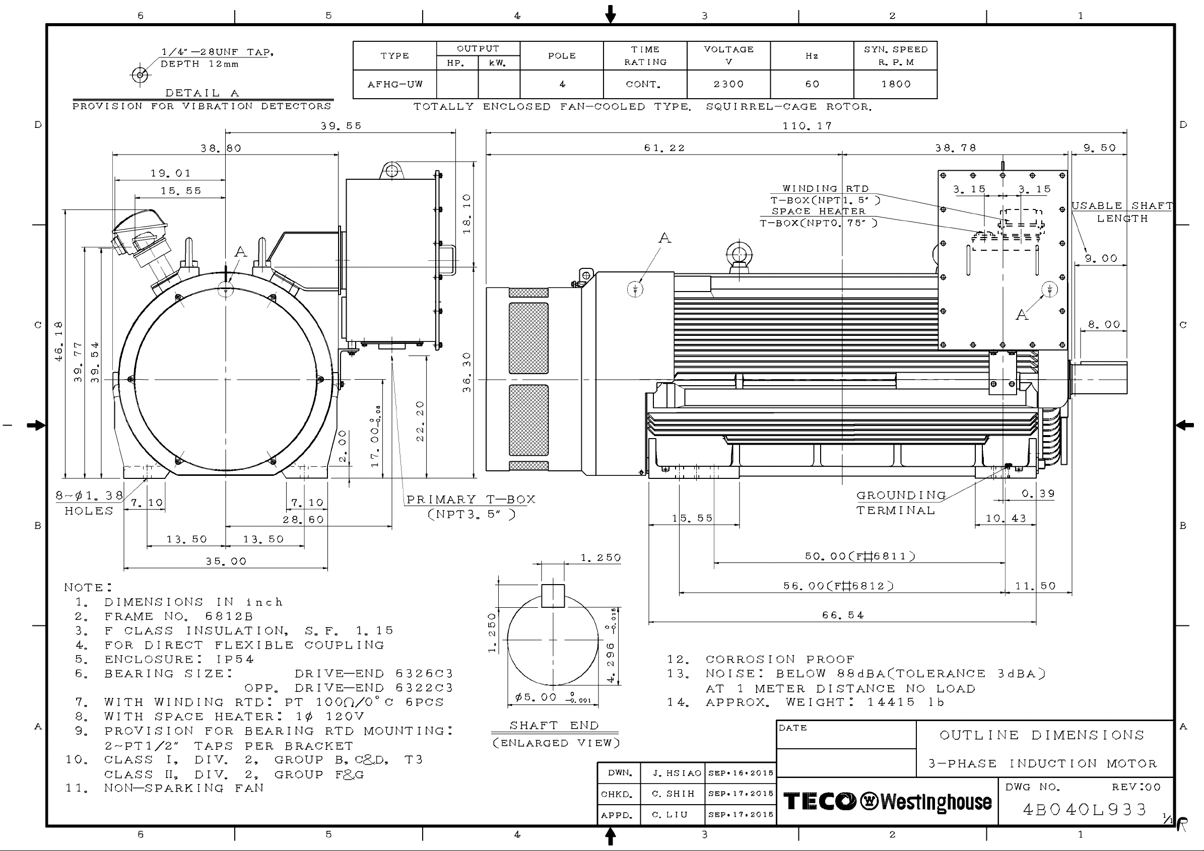
TEFC, 4P 4160V 60HZ
OUTPUT FULL FRAME EFFICIENCY ROTOR Max. LoadPOWER FACTOR CURRENT TORQUE Safe Stall
Starting
LOAD SIZE FULL 3/4 1/2 FULL 3/4 1/2
HP (kW) LOAD LOAD LOAD LOAD LOAD LOAD
RPM (EG) % %
350
% % % %
94.8 93.9
85.1 81.3 71.5260 1787 5009B 95.0 77245 90 230H 177621 25 137
Rated
A %
Starting
345
NEMA
Starting
CODE
LETTER
A
Max. Time(s)
HOT COLD
% % SEC SEC
WR
lb-ft
( 4160V )
APPROX.
2
2
WR
lb-ft
2
WEIGHT
2
LBS
3740
730
735
736
350
443
437
591
612
699
874
936
997
1232
H
G
H
G
220
G
G
G
G
G
H
H
H
300 1786 5011B 95.0 94.9 94.2 86.4 83.0 74.2 69051 80G 220 22 27 2007
400
340 1788 5011B 95.0 94.8 94.1
450
375 1786 5011B 95.0 94.9 94.3 87.1 84.4 75.8 69563 80 220 23 28 2439
500
450 1787 5011B 95.2 95.1 94.6
600
520 1788 5810B 95.4 95.2 94.4 81.3 77.3 31 35 325667.5 65893 110
700
600 1788 5810B 95.6 95.4 94.7
800
670 1788 5810B 95.6 95.4 94.8 81.3 78.1 68.5 658 120 230787 30 33 4032
900
750 1790 6808B 95.6 95.1 93.9
1000
800 1789 6808B 95.8 95.3 94.2 79.1 75.2 65.1 639 120 220 22 24 4298
1070
850 1789 6810B 95.9 95.4 94.4
1140
930 1790 6810B 96.0 35 4878
1250
1120 1790 6810B 96.1 95.6 94.5
1500
1320 1790 6811B 96.3 95.9 95.0 81.2 78.2 69.4 234 58311095120 220 22 251724
1750
95.6 94.6 79.6 75.9 66.1 120 220 31
85.7 82.1 73.3 76558 90 230 222020 26 4840196
85.0 80.3 69.4 76677 90 230 285920 26 216
82.5 79.3 70.6 662 110 220
106
120
78.4 74.0 64.0 630 120 220 406123 25 556
139
146
80.2 76.5 67.4 650 120 220 452933 37 703
153
169
80.5 76.8 67.4 120 2201478 517429 33 954
201
NOTE:
1. Test standard:IEEE-112.
2. Tolerance:NEMA MG1.
3. Number of consec. starts:2 Cold 1 Hot.
4. Data presented in rating lists are typical values. Guaranteed values on request.
Legally binding performance and specification data is given to the end user once each order is confirmed.
5. This performance data is only for sinepower, not suitable for PWM power source.
6. The voltage and frequency combinations not included in performance data are quoted case by case.
168
201
291
378
640
734
4540
4930
5025
6865
365331 35 351
7000
7260
9365
9515
10625
10810
12180
13270
1439526 30 1189 64531971 H 120 22078.0 69.4 265 74396.5 96.1 95.3 81.32000 1500 1790 6812B
TECO Electric & Machinery Co., Ltd.
DWG NO.
3A057M047E
REV.01
2/4
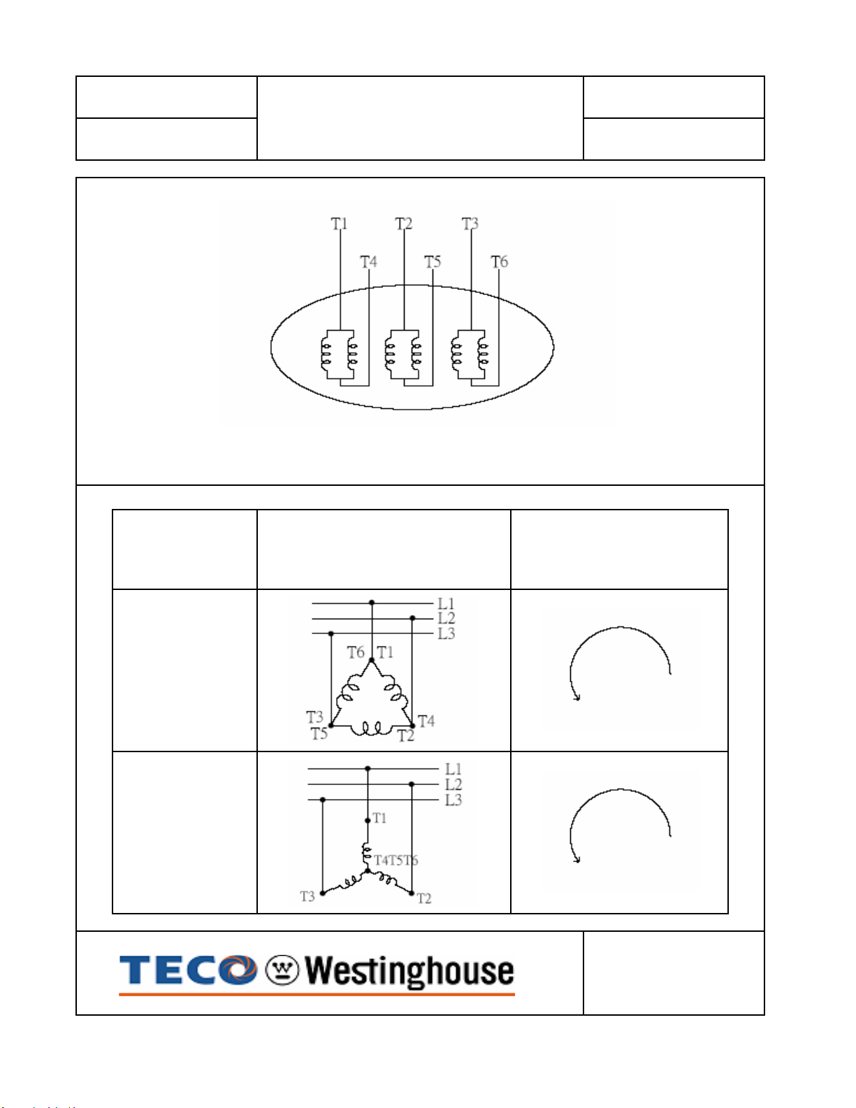
ROTATION
DATE: CATALOG NO.:
CONNECTION DIAGRAM
August 10, 2010
VOLTAGE CONNECTION
KF8008
SCHEMATIC DIAGRAM - 6 LEADS
(VIEWED FROM
2300
4160
DRIVE END)
DWG. NO.
3A061H475

OPERATION
&
MAINTENANCE
MANUAL
FOR
THREE PHASE
INDUCTION
MOTORS
Frame Size 5000 and Larger
10
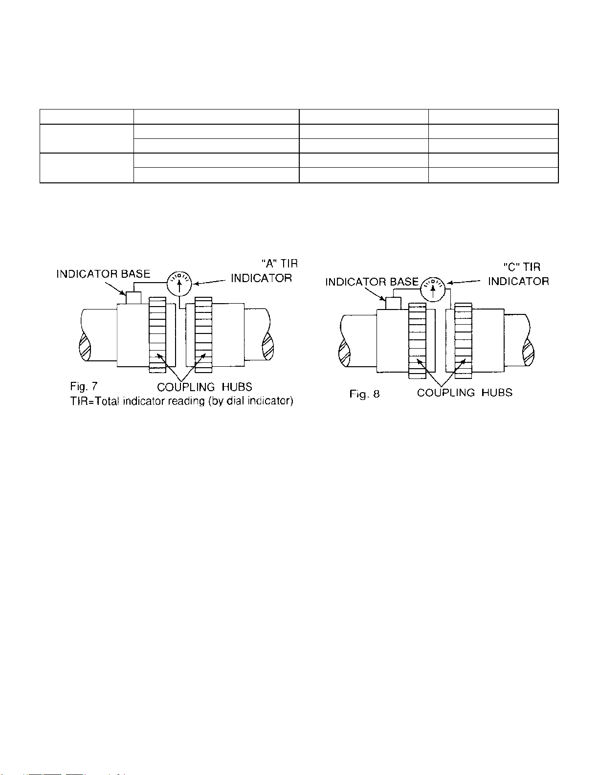
The motor shaft and the driven shaft should be aligned within the following tolerances in both
angular and parallel alignment:
Unit: mm
TIR Range of rotating speed Solid coupling Flexible coupling
C
A
2500 rpm and above 0.03 0.03
Below 2500 rpm 0.04 0.05
2500 rpm and above 0.03 0.03
Below 2500 rpm 0.03 0.04
Angular misalignment is the amount by which the centerlines of driver and driven shafts are
skewed. It can be measured using a dial indicator set up as shown in Fig. 7. The couplings are
rotated together through 360 degrees so that the indicator does not measure runout of the
coupling hub face. The shafts should be forced against either the in or out extreme of their end
float while being rotated.
Parallel misalignment is the amount by which the centerlines of the driver and driven shafts are
out of parallel. It can be measured using a dial indicator set up as shown in Fig. 8. Again, the
couplings are rotated together through 360 degrees so that the indicator does not measure runout
of the coupling hub outside diameter.
3.3.7
After the motor has been properly aligned with the driven equipment and the hold-down bolts
have been installed and tightened, for motors with fabricated frames, at least two dowel pins
should be installed in two diagonally opposite motor feet.
3.3.8 Installation of shaft coupling: (Vertical hollow shaft motor only)
Bolted Coupling as shown in Fig. 9
(a) Bearings are provided to absorb some upward shaft thrust when the coupling is fitted.
(b) The coupling is fastened with bolts.
(c) This coupling type is not auto-release type.
Note: Standard high thrust motors can absorb momentary up-thrust load up to 30% of the
standard down thrust load. If the up-thrust is long in duration (over 10 Seconds) and/or
exceeds 30% of the standard high thrust rating, special design arrangements are
required and standard motor is not suitable.
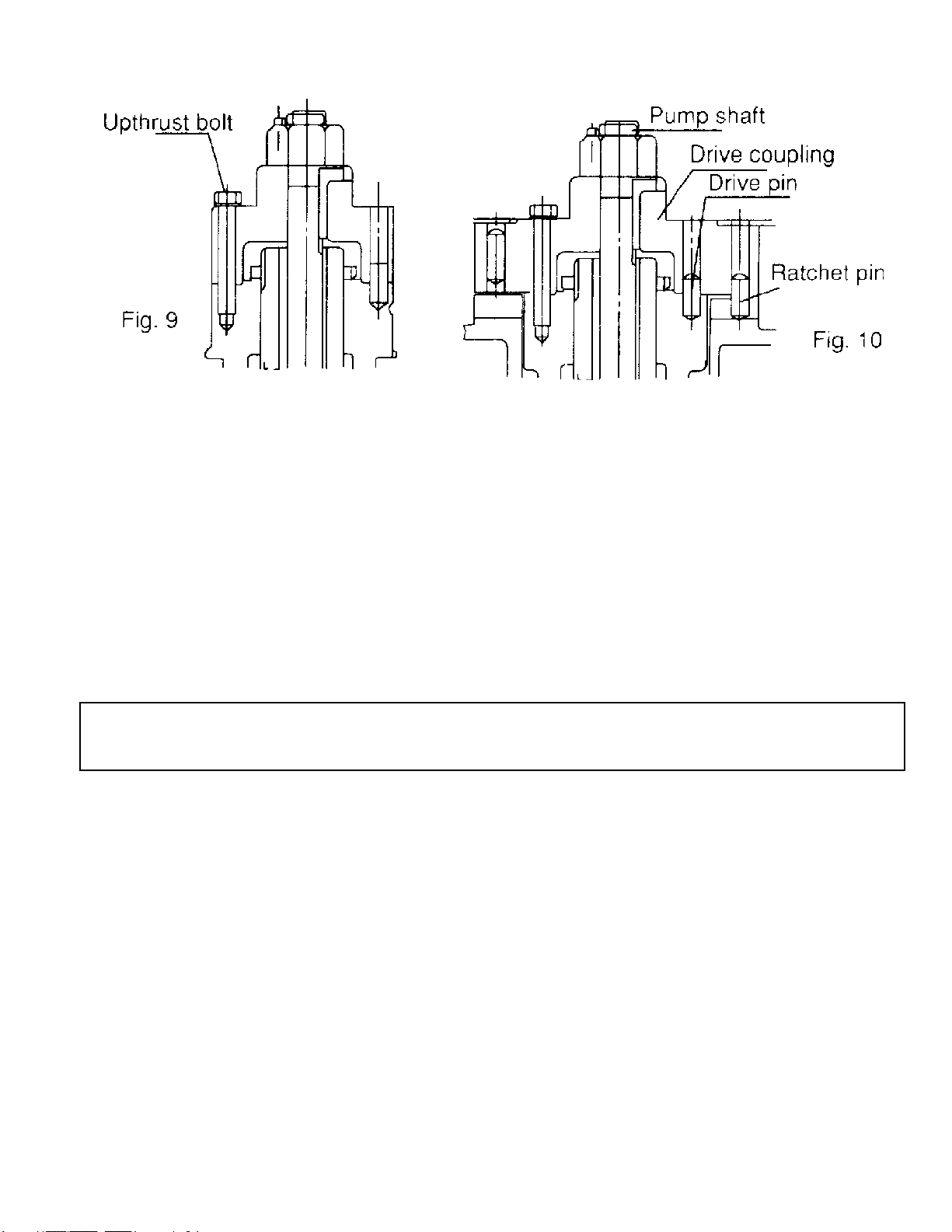
3.3.9 Non-reverse ratchet/coupling, as Fig. 10 (If necessary)
ATTENTION!
The non-reverse coupling is also a bolted type and,
(a) It prevents the pump and motor from rotating in the reverse direction.
(b) It also prevents damage from over speeding and damage to pump shaft and bearings.
(c) The ratchet pins are lifted by the ratchet teeth and are held clear by centrifugal force and
friction as the motor comes up to speed.
(d) When power is removed, speed decreases, and the pins fall. At the instant of reversal, a
pin will catch in a ratchet tooth and prevent backward rotation.
(e) When installing the non-reverse coupling, do not use lubricant. Lubricant will interfere with
proper operation. The top half of the coupling should seat solidly on the lower half and the
pins should touch the bottom of the pockets between the teeth in the plate.
(f) As with the bolted coupling, the up-thrust capabilities are 30% of the standard high thrust
rating for down thrust.
Do not apply non-reverse ratchets on applications in which the pump reversal time from
shutdown (the instant the stop button is pressed) to zero speed is less than one second.
3.4 Installation for belt drive
In general, power transmission through direct flexible coupling is appropriate for large motors.
Such motors are not suitable for belt, chain or gear connection unless specially designed for such
service. However, for small and medium motors with outputs within the ranges shown on the
table below, it is acceptable to use belt transmission as indicated. Beyond these ranges, do not
apply belt sheaves unless specially designed.
3.4.1
The diameter ratio between conveyance sheaves should not be greater than 5 to 1 for flat belts,
and 8 to 1 for V-belts. It is also advisable to limit the belt velocity to under 35m/sec (115 ft/sec) to
limit belt abrasion and vibration. The smaller the outer diameter of the V-belt sheave, the greater
the shaft bending stress will be. If the bending stress is in excess of the shaft fatigue stress, the
shaft may break. Therefore, please inform TWMC when you have decided the size of the
sheaves and the length of the belts upon ordering.
11
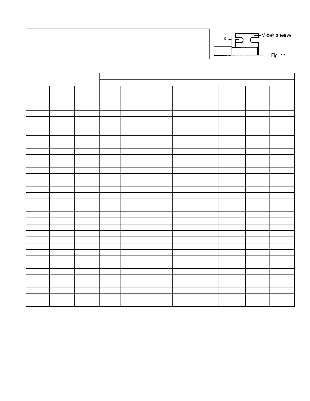
ATTENTION!
Place the sheave and belt as close as possible to the motor
body (it is advisable to make x as shown in Fig. 11 equal to 0)
to reduce the bending moment and improve shaft life.
3.4.2 Table of belt-sheave application for general electric motors
Output
(KW/HP)
4P 6P 8P
11/15 - - B 4 160 82 3V 4 125 48
- 11/15 - B 5 170 101 3V 5 140 59
- - 11/15 B 5 190 101 3V 6 160 69
15/20 - - B 5 170 101 3V 6 125 69
- 15/20 - B 5 224 101 3V 6 160 69
- - 15/20 C 4 224 111 5V 3 180 60
18.5/25 - - B 5 200 101 3V 6 140 69
- 18.5/25 - C 4 224 111 5V 3 180 60
- - 18.5/25 C 5 224 136 5V 4 180 78
22/30 - - B 5 224 101 5V 6 160 69
- 22/30 - C 5 224 136 3V 4 180 78
- - 22/30 C 5 250 136 5V 4 200 78
30/40 - - C 5 224 136 5V 4 180 78
- 30/40 - C 5 265 136 5V 4 224 78
- - 30/40 C 6 265 162 5V 5 224 95
37/50 - - C 6 224 162 5V 4 200 78
- 37/50 - C 6 265 162 5V 4 224 78
- - 37/50 C 7 280 187 5V 5 250 95
45/60 - - C 6 265 162 5V 4 224 78
- 45/60 - C 7 280 187 5V 5 224 95
- - 45/60 C 7 315 187 5V 6 250 113
55/75 - - C 7 265 187 5V 5 224 95
- 55/75 - C 8 300 213 5V 6 250 113
- - 55/75 D 5 355 196 5V 6 280 113
75/100 - - C 8 315 213 5V 6 250 113
- 75/100 - D 6 355 233 5V 6 315 113
- - 75/1 00 D 6 400 233 5V 6 355 113
- 90/120 - D 6 400 233 5V 6 355 113
- - 90/120 D 6 425 233 8V 4 355 124
- 110/150 - D 7 400 270 8V 4 355 124
- 132/175 110/150 D 7 450 270 8V 4 400 124
- 160/200 132/1 75
V-Belt
Type
Conventional V-Belts Narrow V-Belts
Number
Of
Belts
D 9 450 344 8V 4 450 124
Min.
PCD
(mm)
V-Belt Sheave
Max
Width
(mm)
V-Belt
Type
Number
Of
Belts
Min.
PCD
(mm)
Width
Max
(mm)
3.5 Conveyance with chain or gear
3.5.1
Make sure the loading capacity of shaft and bearings is appropriate for the size and installation
position (overhung) of chain and gear. If necessary, please contact us to ensure the shaft and
bearings will meet your requirements.
12
3.5.2
Pay close attention to ensure the parallelism of shafts.
3.5.3
The teeth of couplings should be correctly and precisely matched; the force conveyance
centers should lie on the same line.
3.5.4
There should be no skip, jumping, vibration or unusual noises.
ATTENTION!
Do not hammer conveyance devices such as couplings, belt sheaves, chain wheels, gears
etc. onto the shaft. Conveyance devices should be fitted and removed only by means of
suitable devices. Heat shrinking may be a better alternative to avoid damaging bearings
and components.
3.6 Electrical connections
All interconnecting wiring for controls and grounding should be in strict accordance with local
requirements such as the USA National Electrical Code and UK IEE wiring regulations. Wiring of
motor and control, overload protection and grounding should follow the instructions of connection
diagrams attached to the motor.
3.6.1 Power
The rated conditions of operation for the motor are as shown on the nameplate. Within the limits,
given below, of voltage and frequency variation from the nameplate values, the motor will
continue to operate but with performance characteristics that may differ from those at rated
conditions:
Operating the motor at voltages and frequencies outside of the above limits can result in both
unsatisfactory motor performance and damage to or failure of the motor.
3.6.2
The main lead box furnished with the motor has been sized to provide adequate space for the
make-up of the connections between the motor lead cables and the incoming power cables.
3.6.3
Either fabricated motors or fan cooled cast frame, motors are all provided with grounding pads or
bolts.
The exposed rotating parts should be covered to prevent accidents.
±10% of rated voltage
±5% of rated frequency
±10% combined voltage and frequency variation so long as frequency variation is
no more than ±5% of rated.
The bolted joints between the motor lead and the power cables must be made and
insulated in a workman-like manner following the best trade practices.
The motor must be grounded by proper connection to the electrical system ground.
13
3.6.4
The rotation direction of the motor will be as shown by either a nameplate on the motor or the
outline drawing. The required phase rotation of the incoming power for this motor rotation may
also be stated. If either is unknown, the correct sequence can be determined in the following
manner: While the motor is uncoupled from the load, start the motor and observe the direction of
rotation. Allow the motor to achieve full speed before disconnecting it from the power source.
Refer to the operation section of these instructions for information concerning initial start-up. If
resulting rotation is incorrect, it can be reversed by interchanging any two (2) incoming cables.
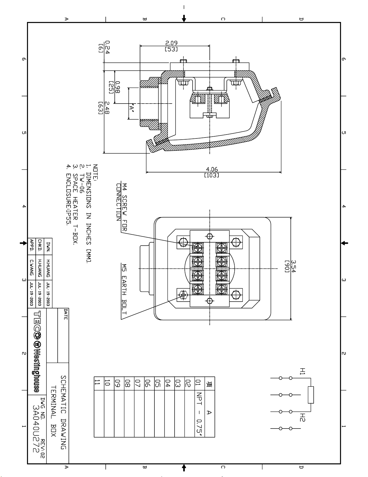
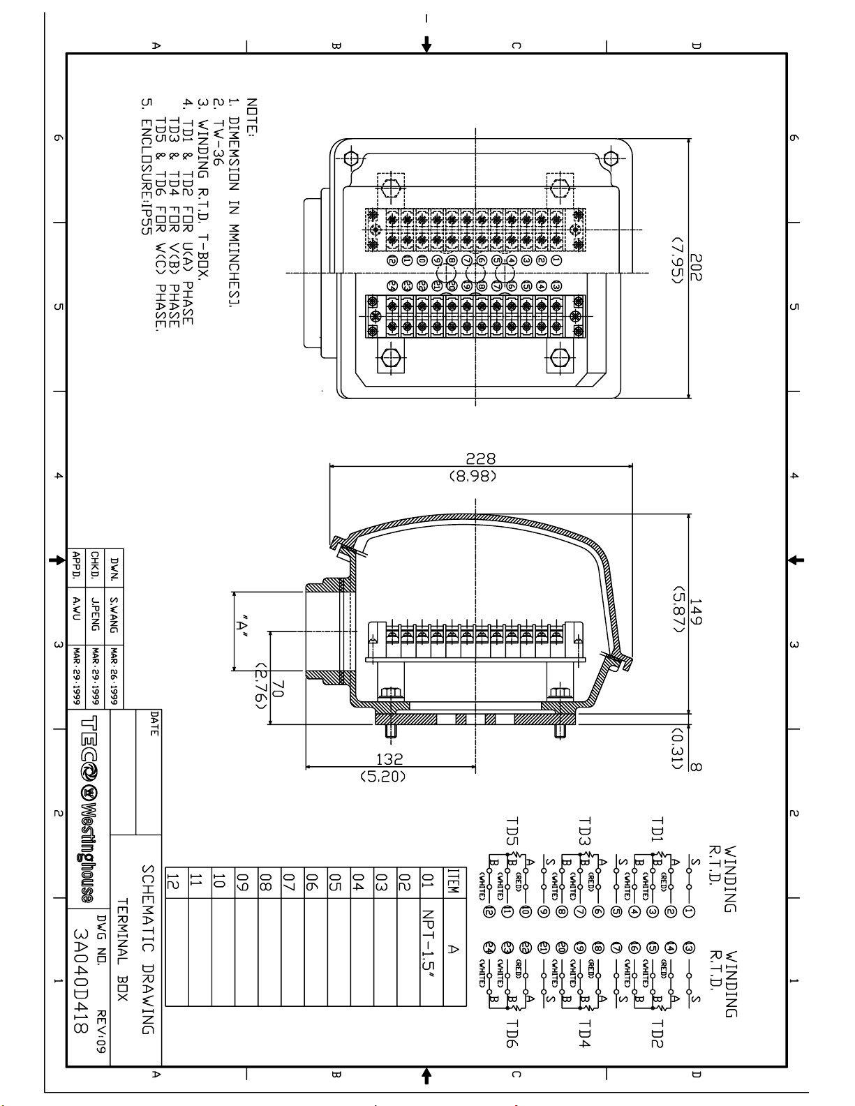
3.6.5 Auxiliary devices
Auxiliary devices such as resistance temperature detectors, thermocouples, thermoguards, etc.,
will generally terminate on terminal blocks located in the auxiliary terminal box on the motor.
Other devices may terminate in their own enclosures elsewhere on the motor. Such information
can be obtained by referring to the outline drawing. Information regarding terminal designation
and the connection of auxiliary devices can be obtained from auxiliary drawings or attached
nameplates.
If the motor is provided with internal space heaters, the incoming voltage supplied to them must
be exactly as shown by either a nameplate on the motor or the outline drawing for proper heater
operation.
Caution must be exercised anytime contact is made with the incoming space
heater circuit as space heater voltage is often automatically applied when the
motor is shutdown.
4. OPERATION
4.1 Examination before start
4.1.1
When motors are installed in good manner, ensure the wiring is according to the diagram. Also,
the following points should be noted:
(a) Make sure all wiring is correct.
(b) Ensure the sizes of cable wires are appropriate and all connections are well made for the
currents they will carry.
(c) Ensure all connections are properly insulated for the voltage and temperature they will
experience.
(d) Ensure the capacity of fuses, switches, magnetic switches and thermo relays etc. are
appropriate and the contactors are in good condition.
(e) Make sure the frame and terminal box are grounded.
(f) Make sure that the starting method is correct.
(g) Make sure switches and starters are set at their right positions.
(h) Motor heaters must be switched off when the motor is running.
4.1.2 Measurement of insulation resistance
During and immediately after measuring, the terminals must not be touched as they
may carry residual dangerous voltages. Furthermore, if power cables are
connected, make sure that the power supplies are clearly disconnected and there
are no moving parts.
14

(a) For rated voltage below 1000V, measured with a 500VDC megger.
(b) For rated voltage above 1 000V, measured with a 1 000VDC megger.
(c) In accordance with IEEE 43, clause 9.3, the following formula should be applied:
Rated voltage (v)
R≥( 1000 + 1) x 10(MΩ)
(d) On a new winding, where the contaminant causing low insulation resistance is generally
moisture, drying the winding through the proper application of heat will normally increase
the insulation resistance to an acceptable level. The following are several accepted
methods for applying heat to the winding:
(1) If the motor is equipped with space heaters, they can be energized to heat the
winding.
(2) Direct current (as from a welder) can be passed through the winding. The total current
should not exceed approximately 50% of rated full load current. If the motor has only
three leads, two must be connected together to form one circuit through the winding.
In this case, one phase will carry the fully applied current and each of the others, onehalf each. If the motor has six leads (3 mains and 3 neutrals), the three phases should
be connected into one series circuit.
ATTENTION!
Caution must be exercised, when heating the motor with any source of heat other than self
contained space heaters, to raise the winding temperature at a gradual rate to allow any
entrapped moisture to vaporize and escape without rupturing the insulation. The entire
heating cycle should extend over 15-20 hours.
(e) Should the resistance fail to attain the specified value even after drying, careful
Ensure there is adequate guarding so live parts cannot be touched.
(3) Heated air can either blown directly into the motor or into a temporary enclosure
surrounding the motor. The source of heated air should preferably be electrical as
opposed to fueled (such as kerosene) where a malfunction of the fuel burner could
result in carbon entering the motor.
Insulation resistance measurements can be made while the winding is being heated.
However, they must be corrected to 40°C for evaluation since the actual insulation
resistance will decrease with increasing temperature. As an approximation for a new
winding, the insulation resistance will approximately halve for each 10°C increase in
insulation temperature above the dew point temperature.
examination should be undertaken to eliminate all other possible causes, if any.
4.1.3 Power Source
(a) Ensure the capacity of the power source is sufficient.
(b) Ensure the supply voltage and frequency ratings are identical to those on the nameplate.
(c) Voltage variation should be confined to within ±10% of the rated value and the phase to
phase voltages should be balanced.
15
 Loading...