

Page 1

Page 2

I
Table of Contents
Preface
0-1
Chapter 1 Safety Precautions
1-1
1.1 Before Power UP
1-1
1.2 During Power UP
1-2
1.3 Before Operation
1-2
1.4 During Operation
1-2
1.5 Inverter Disposal
1-3
Chapter 2 Model Description
2-1
2.1 Nameplate Data
2-1
2.2 Model Identification
2-1
2.3 Standard Product Specification
2-2
Chapter 3 Environment & Installation
3-1
3.1 Environment
3-1
3.2 Installation
3-3
3.2.1 Installation method
3-3
3.2.2 Installation space
3-21
3.2.3 De-rating curves
3.2.4 Capacitor reforming Guide after long storage
3-22
3-22
3.3 Wiring guidelines
3-23
3.3.1 Power Cables
3-23
3.3.2 Control Cable selection and Wiring
3-23
3.3.3 Wiring and EMC guidelines
3-24
3.3.4 Failure liability
3-25
3.3.5 Considerations for peripheral equipment
3-26
3.3.6 Ground connection
3-27
3.3.7 Inverter exterior
3-28
3.4 Specifications
3-37
3.4.1 Product Specifications
3-37
3.4.2 General Specifications
3-39
3.5 Standard wiring
3-41
3.5.1 Single phase
3-41
3.5.2 Single/ Three phase
3-42
3.5.3 Three phase
3-43
3.6 Terminal Description
3-44
3.6.1 Description of main circuit terminals
3-44
3.6.2 Control circuit terminal description
3-46
3.7 Outline Dimensions
3-48
3.7.1 IP20/NEMA1 dimensions
3-48
3.7.2 IP66/NEMA4X dimensions
3-58
3.8 EMC filter disconnection
3-61
3.9 The Dimension and Installation of Operator panel
3-62
3.9.1 Description of dimension and installation
3-62
Page 3

II
3.9.2 Description of Protective Cover
3-64
Chapter 4 Software Index
4-1
4.1 Keypad Description
4-1
4.1.1 Operator Panel Functions
4-1
4.1.2 Digital display Description
4-2
4.1.3 Digital display setup
4-4
4.1.4 Example of Keypad Operation
4-5
4.1.5 Operation Control
4-7
4.2 Programmable Parameter Groups
4-8
4.3 Parameter Function Description
4-28
4.4 Specification Description on Built-in PLC Function
4-81
4.4.1 Basic Instruction Set
4-81
4.4.2 Function of Basic Instructions
4-82
4.4.3 Application Instructions
4-83
Chapter 5 Troubleshooting and Maintenance
5-1
5.1 Error Display and Corrective Action
5-1
5.1.1 Manual Reset and Auto-Reset
5-1
5.1.2 Keypad Operation Error Instruction
5-3
5.1.3 Special conditions
5-4
5.2 General troubleshooting
5-5
5.3 Troubleshooting of the Inverter
5-6
5.3.1 Quick troubleshooting of the Inverter
5-6
5.3.2 Troubleshooting for OC, OL error displays
5-8
5.3.3 Troubleshooting for OV, LV error
5-9
5.3.4 Motor not running
5-10
5.3.5 Motor Overheating
5-11
5.3.6 Motor runs unbalanced
5-12
5.4 Routine and periodic inspection
5-13
5.5 Maintenance
5-14
Chapter 6 Peripheral Components
6-1
6.1 Reactor Specifications
6-1
6.2 Electromagnetic Contactor circuit breaker
6-1
6.3 Fuse Specification
6-2
6.4 Fuse Specification(UL Model Recommended)
6-2
6.5 Brake Resistor
6-3
6.6 Noise filter
6-4
Appendix 1
Instructions for UL
App1-1
Appendix 2
E510 Parameter Setting List
App2-1
Appendix 3
E510 MODBUS Communication protocol
App3-1
Appendix 4
E510 PLC Communication protocol
App4-1
Appendix 5
JN5-CM-USB instruction manual
App5-1
Appendix 6
510 series accessories manual
App6-1
Page 4

0-1
Preface
To extend the performance of the product and ensure personnel safety, please read
this manual thoroughly before using the inverter. Should there be any problem in using the
product that cannot be solved with the information provided in the manual, contact Our’s
technical or sales representative who will be willing to help you.
※Precautions
The inverter is an electrical product. For your safety, there are symbols such as
“Danger”, “Caution” in this manual as a reminder to pay attention to safety instructions on
handling, installing, operating, and checking the inverter. Be sure to follow the instructions
for highest safety.
Danger
Indicates a potential hazard that could cause death or serious
personal injury if misused.
Caution
Indicates that the inverter or the mechanical system might be
damaged if misused.
Danger
Risk of electric shock. The DC link capacitors remain charged for five
minutes after power has been removed. It is not permissible to open the
equipment until 5 minutes after the power has been removed.
Do not make any connections when the inverter is powered on. Do not check
parts and signals on circuit boards during the inverter operation.
Do not disassemble the inverter or modify any internal wires, circuits, or
parts.
Ensure that the Inveter Ground terminal is connected correctly.
Caution
Do not perform a voltage test on parts inside the inverter. High voltage can
destroy the semiconductor components.
Do not connect T1, T2, and T3 terminals of the inverter to any AC input power
supply.
CMOS ICs on the inverter’s main board are susceptible to static electricity. Do
not touch the main circuit board.
Page 5
1-1
Chapter 1 Safety Precautions
1.1 Before Power Up
Danger
Make sure the main circuit connections are correct Single phase L1(L),L3(N),
Three phase L1(L),L2,L3(N) are power-input terminals and must not be
mistaken for T1,T2 and T3. Otherwise, inverter damage can result.
Caution
The line voltage applied must comply with the inverter’s specified input
voltage.(See the nameplate)
To avoid the front cover from disengaging, or other damge do not carry the
inverter by its covers. Support the drive by the heat sink when transporting.
Improper handling can damage the inverter or injure personnel and should be
avoided.
To avoid the risk of fire, do not install the inverter on a flammable object.Install on
nonflammable objects such as metal.
This product provides the 24V for internal use only, do not use as the power
supply sources for other external components, such as sensors, electronic
components ... etc., otherwise it will cause adverse situation.
When disconnecting the remote keypad, turn the power off first to avoid any
damage to the keypad or the inverter.
Caution
This product is sold subject to EN 61800-3 and EN 61800-5-1.
In a domestic environment this product may cause radio interference in which
case the user may be required to apply corrective measures.
Motor over temperature protection is not provided.
Caution
Work on the device/system by unqualified personnel or failure to comply with
warnings can result in severe personal injury or serious damage to material. Only
suitably qualified personnel trained in the setup, installation, commissioning and
operation of the product should carry out work on the device/system.
Only permanently-wired input power connections are allowed.
Page 6
1-2
1.2 During Power Up
Danger
When the momentary power los s is longer than 2 seconds, the inverter will not
have sufficient stored power for its control circuit. Therefore, when the power is
re-applied, the run operation of the inverter will be based on the setup of
following parameters:
Run parameters. 00-02 or 00-03.
Direct run on power up. Parameter. 07-04 and the status of external run
switch,
Note-: the start operation will be regardless of the settings for parameters
07-00/07-01/07-02.
Danger. Direct run on power up.
If direct run on power up is enabled and inverter is set to external run
with the run FWD/REV switch closed then the inverter will restart.
Danger
Prior to use, ensure that all risks and safety implications are considered.
When the momentary power loss ride through is selected and the power loss is
short, the inverter will have sufficient stored power for its control circuits to
function, therefore,when the power is resumed the inverter will automatically
restart depending on the setup of parameters 07-00 & &- 7-01.
1.3 Before Operation
Caution
Make sure the inverter model and rating are the same as that set in parameter
13-00.
Note :On power up the supply voltage set in parameter 01-01 will flash on the
display for 2 seconds.
1.4 During Operation
Danger
Do not connect or disconnect the motor during operation. Otherwise, It may
cause the inverter to trip or damage the unit.
Page 7

1-3
Caution
Do not touch heat radiating components such as heat sinks and brake
resistors.
The inverter can drive the motor from low speed to high speed. Verify the
allowable speed ranges of the motor and the associated machinery.
Risk of electric shock. The DC link capacitors remain charged for five minutes
after power has been removed. It is not permissible to open the equipment until 5
minutes after the power has been removed.
Caution
The Inverter should be used in environments with temperature range from
(14-104°F) or (-10 to 50°C)* and relative humidity of 95%.
* IP20 : -10 ~ 50 °C without stick on type dust cover.
NEMA1 : -10 ~ 40 °C with stick on type dust cover.
Danger
Make sure that the power is switched off before disassembling or checking any
components.
1.5 Inverter Disposal
Caution
Please dispose of this unit with care as an industrial waste and according to your
required local regulations.
The capacitors of inverter main circuit and printed circuit board are considered as
hazardous waste and must not be burnt.
The plastic enclosure and parts of the inverter such as the cover board will
release harmful gases if burnt.
Danger
To avoid electric shock, do not take the front cover off while power is on.
The motor will restart automatically after stop when auto-restart function is
enabled. In this case, care must be taken while working around the drive and
associated equipment .
The operation of the stop switch is different than that of the emergency stop
switch. The stop switch has to be activated to be effective. Emergency stop has
to be de-activated to become effective.
Page 8
2-1
Chapter 2 Model Description
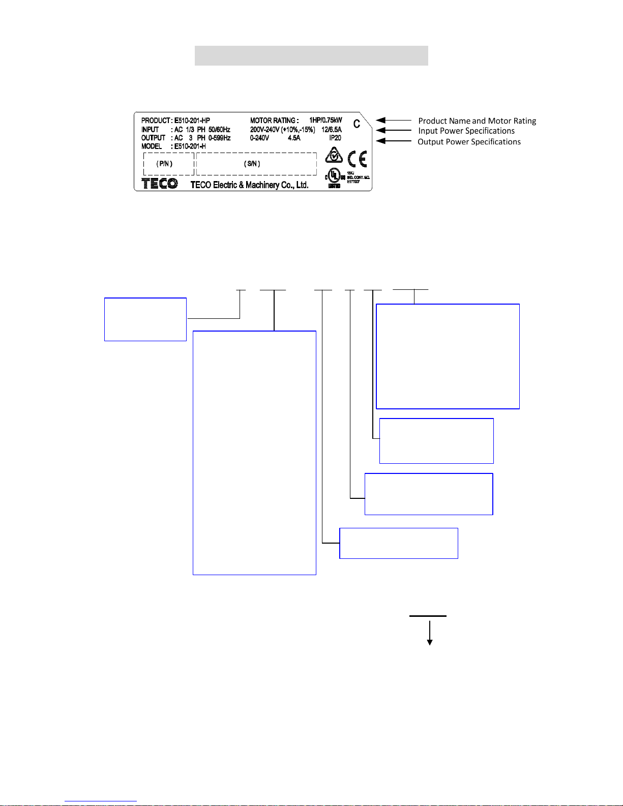
2.1 Nameplate Data
2.2 Model Identification
E510 - 2 P5 - H 1 F N4S
Power supply
1: Single phase
3: Three phase
Specification
H:Standard Type
Supply voltage
2:200V Class
4:400V Class
Horsepower
200V Class P5: 0.5 HP
01: 1 HP
02: 2 HP
03: 3 HP
05: 5 HP
08: 8 HP
10: 10 H P
15 : 15 HP
20: 20 H P
400V Class 01: 1 HP
02: 2 HP
03: 3 HP
05: 5 HP
08: 8 HP
10: 10 H P
15: 15 H P
20: 20 H P
25: 25 H P
EMC Filter
F :Built-in
Blank:None
Structure:
N4S: IP66/Built-in VR+Switch
N4:IP66
N4R:IP66/Built-in V R
Blank:IP20
E510–4 20–H 3 F PT
PT: footprint type filter
Page 9

2-2
2.3 Standard Product Specification
IP20 / NEMA 1 Type
Model
Supply
voltage (Vac)
(HP) (KW)
Filter
Frame
Size
V X
E510-2P5-H1F
1 ph,
200~240V
(+10%-15%)
50/60 Hz
0.5 0.4
◎
1
E510-201-H1F 1 0.75
◎
1
E510-202-H1F 2 1.5
◎
2
E510-203-H1F 3 2.2
◎
2
E510-2P5-H
1 & 3 ph,
200~240V
(+10%-15%)
50/60 Hz
0.5 0.4
◎
1
E510-201-H 1 0.75
◎
1
E510-202-H 2 1.5
◎
2
E510-203-H 3 2.2
◎
2
E510-202-H3
3ph,
200~240V
(+10%-15%)
50/60 Hz
2 1.5
◎
1
E510-205-H3 5 3.7
◎
2
E510-208-H3 7.5 5.5
◎
3
E510-210-H3 10 7.5
◎
3
E510-215-H3 15 11
◎
4
E510-220-H3 20 15
◎
4
E510-401-H3F
3ph,
380~480V
(+10%-15%)
50/60 Hz
1 0.75
◎
1
E510-401-H3 1 0.75
◎
1
E510-402-H3F 2 1.5
◎
1
E510-402-H3 2 1.5
◎
1
E510-403-H3F 3 2.2
◎
2
E510-403-H3 3 2.2
◎
2
E510-405-H3F 5 3.7
◎
2
E510-405-H3 5 3.7
◎
2
E510-408-H3F 7.5 5.5
◎
3
E510-408-H3 7.5 5.5
◎
3
E510-410-H3F 10 7.5
◎
3
E510-410-H3 10 7.5
◎
3
E510-415-H3F 15 11
◎
3
E510-415-H3 15 11
◎
3
E510-420-H3FPT 20 15
◎
4
E510-420-H3F 20 15
◎
4
E510-420-H3 20 15
◎
4
E510-425-H3F 25 18.5
◎
4
E510-425-H3FPT 25 18.5
◎
4
E510-425-H3 25 18.5
◎
4
V : Built-in
X : None
Page 10

2-3
IP66 / NEMA 4X Type
Model
Supply
voltage
(Vac)
HP (KW)
Filter VR Switch
Frame
Size
V X V X V X
E510-2P5-H1FN4S
1 ph
200~240V
+10%-15%
50/60Hz
0.5 0.4
◎
◎
◎
1
E510-201-H1FN4S 1 0.75
◎
◎
◎
1
E510-202-H1FN4S 2 1.5
◎
◎
◎
2
E510-203-H1FN4S 3 2.2
◎
◎
◎
2
E510-2P5-HN4R
1 & 3 ph
200~240V
+10%-15%
50/60Hz
0.5 0.4
◎ ◎
◎
1
E510-201-HN4R 1 0.75
◎ ◎
◎
1
E510-202-HN4R 2 1.5
◎ ◎
◎
2
E510-203-HN4R 3 2.2
◎ ◎
◎
2
E510-205-H3N4
3 ph
200~240V
+10%-15%
50/60Hz
5 3.7
◎
◎
◎
2
E510-208-H3N4 7.5 5.5
◎
◎
◎
3
E510-210-H3N4 10 7.5
◎
◎
◎
3
E510-215-H3N4 15 11
◎
◎
◎
3
E510-220-H3N4 20 15
◎
◎
◎
3
E510-401-H3FN4S
3 ph
380~480V
+10%-15%
50/60Hz
1 0.75
◎
◎
◎
1
E510-401-H3N4 1 0.75
◎
◎
◎
1
E510-402-H3FN4S 2 1.5
◎
◎
◎
1
E510-402-H3N4 2 1.5
◎
◎
◎
1
E510-403-H3FN4S 3 2.2
◎
◎
◎
2
E510-403-H3N4 3 2.2
◎
◎
◎
2
E510-405-H3FN4S 5 3.7
◎
◎
◎
2
E510-405-H3N4 5 3.7
◎
◎
◎
2
E510-408-H3FN4S 7.5 5.5
◎
◎
◎
3
E510-408-H3N4 7.5 5.5
◎
◎
◎
3
E510-410-H3FN4S 10 7.5
◎
◎
◎
3
E510-410-H3N4 10 7.5
◎
◎
◎
3
E510-415-H3FN4S 15 11
◎
◎
◎
3
E510-415-H3N4 15 11
◎
◎
◎
3
E510-420-H3N4 20 15
◎
◎
◎
3
E510-425-H3N4 25 18.5
◎
◎
◎
3
V : Built-in
X : None
Page 11
3-1
Chapter 3 Environment & Installation
3.1 Environment
Installation environment has a direct effect on the correct operation and the life expectancy of the
inverter, Install the inverter in an environment complying with the following conditions:
Protection
Protection class
IP20 / NEMA 1 & IP66 / NEMA 4X (Depending on models)
Suitable Environment
Operating
temperature
IP20 / NEMA 1 type:
–10 ~ 50℃ inside distributor (without sticker on dust cover.),
–10 ~ 40℃ outside distributor (with sticker on dust cover.).
IP66 / NEMA 4X type:
-10~50°C
If several inverters are installed in the same Operator panel, ensure adequate spacing
and provide the necessary cooling and ventilation for successful operation.
Storage
temperature
-20~60°C
Relative
Humidity
Max 95% (without condensation)
Notice prevention of inverter freezing up.(Compliance with IEC 60068-2-78).
Shock
1G. (9.8m/s²) for 20Hz and below.
0.6G (5.88m/s²) from 20Hz to 50Hz (Compliance with IEC 60068-2-6)
Installation site
Install in an environment that will not have an adverse effect on the operation of the unit and
ensure that there is no exposure to areas such as that listed below:-
Direct sunlight, Rain or moisture.
Oil mist and salt
Dust, lint fibbers, small metal filings and Corrosive liquid and gas.
Electromagnetic interference from sources such as welding equipment.
Radioactive and flammable materials.
Excessive vibration from machines such as stamping, punching machines.
add a vibration-proof pads if necessary.
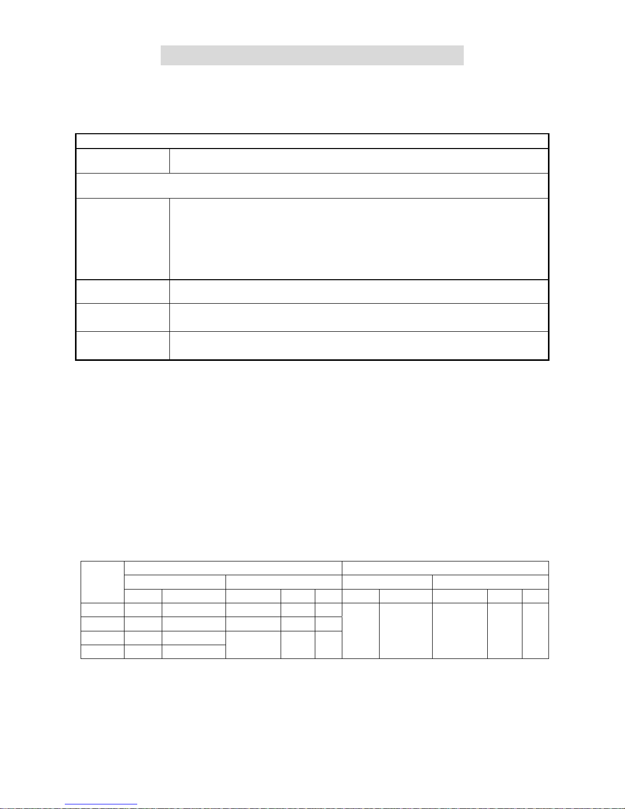
Tightening torque for terminals
Model
TM1 TM2
Cable Size Tightening torque Cable Size Tightening torque
AWG mm² kgf.cm Ibf.in Nm AWG mm² kgf.cm Ibf.in Nm
Frame1 20~12 0.52~3.33
10.20
0.006 1.0
26~14 0.13~2.08
8.16
0.005 0.8
Frame2 18~8 0.81~8.37
18.35
0.010 1.8
Frame3 14~6 2.08~13.30
24.47
0.014 2.4
Frame4 4~3 21.15~26.67
Page 12

3-2
Electrical ratings of terminals
Model Horsepower Power Specification Voltage (Volt) Current(A)
Frame1
0.5/1 200V~240V
600 20
1/2 380V~480V
Frame2
2/3/5 200V~240V
600 45
3/5 380V~480V
Frame 3/4
7.5/10/15/20 200V~240V 600 65
7.5/10/15/20/25 380V~480V 600 100
The maximum rms symmetrical short circuit ratings are as follows.
Device Rating
Short circuit
Rating(A)
Maximum
Voltage (Volt)
voltage HP
220V 0.5~20 5000 240
440V 1~25 5000 480
Page 13

3-3
3.2 Installation
3.2.1 Installation method
3.2.1.1 IP20 / NEMA 1 standard installation
(a)Single/Three phase: 200V 0.5~1HP; Single phase: 200V 0.5~1HP; Three phase: 200V 2HP; 400V
1~2HP;
Frame1 Frame1(NEMA1)
(b)Single/Three phase: 200V 2~3HP; Single phase: 200V 2~3HP; Three phase: 200V 5HP; 400V 3~5HP;
Frame2
Frame2(NEMA1)
Screw M4
Screw M4
Screw M4
Screw M4
Screw M4
Screw M4
Screw M4
Page 14

3-4
(c)Three phase: 200V 7.5~10HP; 400V 7.5~15HP;
Frame3
Frame3(NEMA1)
Screw M4
Screw M4
Screw M4
Screw M4
Page 15
3-5
(d)Three phase: 200V 15~20HP; 400V 20~25HP;
Frame4
Frame4(NEMA1)
Screw M5
Screw M5
Screw M5
Screw M5
Page 16

3-6
(e) Three phase: 400V 20~25HP; (With Fliter Models)
Frame4
(f)400V 20~25HP; (with filter) (E510-420-H3FPT/ E510-425-H3FPT)
M5 螺丝 M5 螺丝
Screw M5 Screw M5
Screw M5
Screw M5
Page 17
3-7
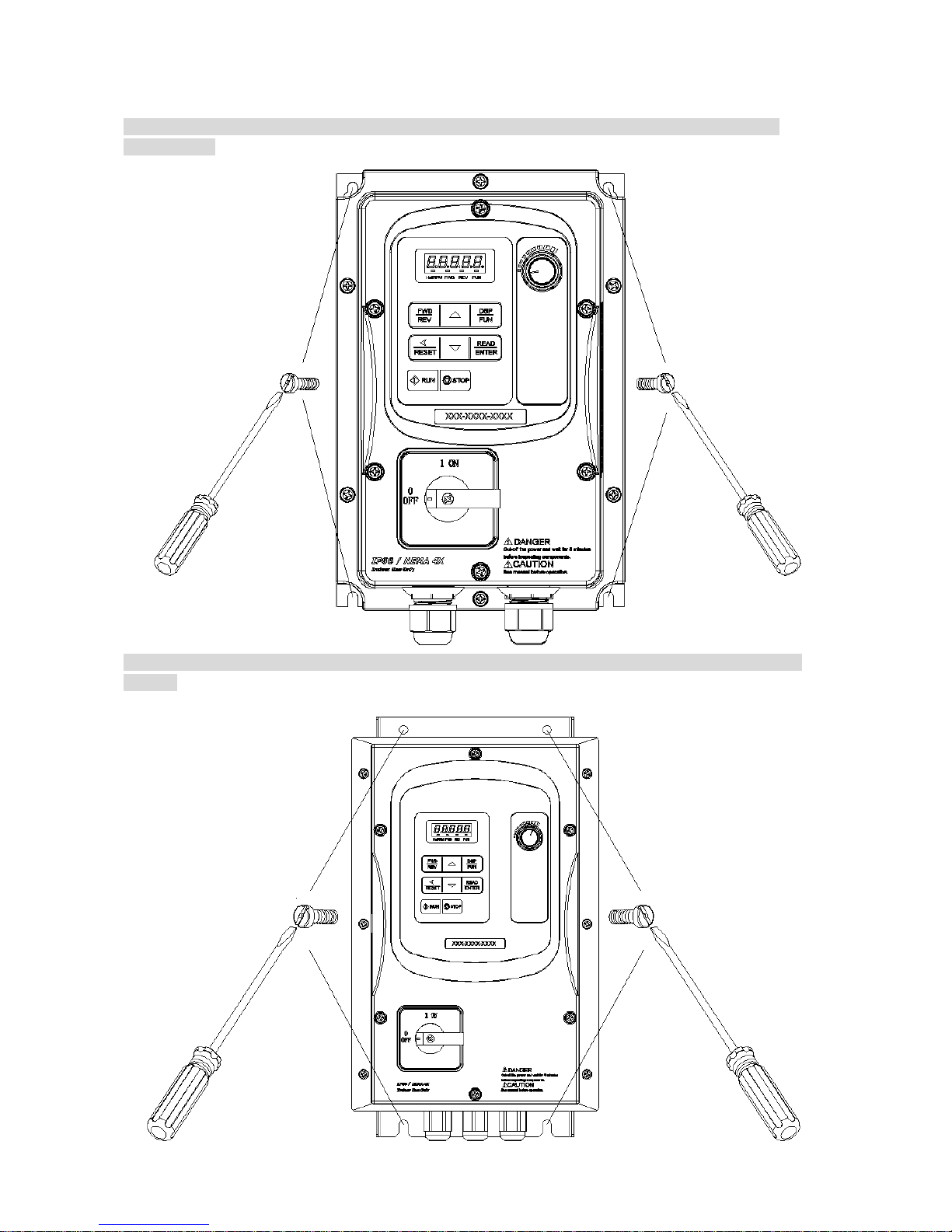
3.2.1.2 IP66/NEMA 4X standard installation
(a)Single/Three phase : 200V 0.5~1HP ; Single phase : 200V 0.5~1HP; Three phase : 200V 2HP ;
400V 1~2HP ;
(b)Single / Three phase: 200V 2~3HP ; Single phase : 200V 2~3HP ; Three phase : 200V5HP ; 400V
3~5HP ;
Screw M5
Screw M5
Screw M6
Screw M6
Page 18
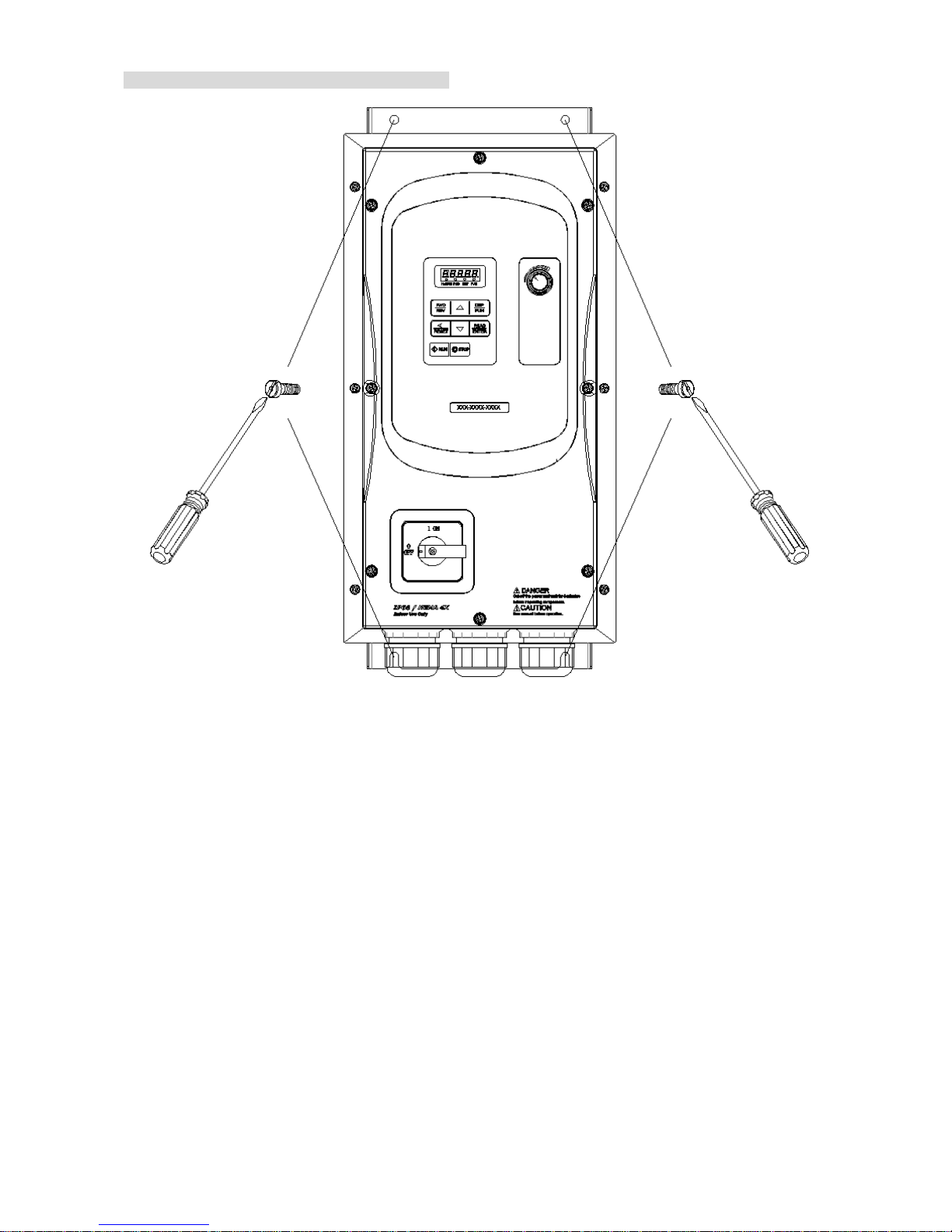
3-8
(c) Three phase : 200V 8~20HP ; 400V 8~25HP ;
Screw M6
Screw M6
Page 19

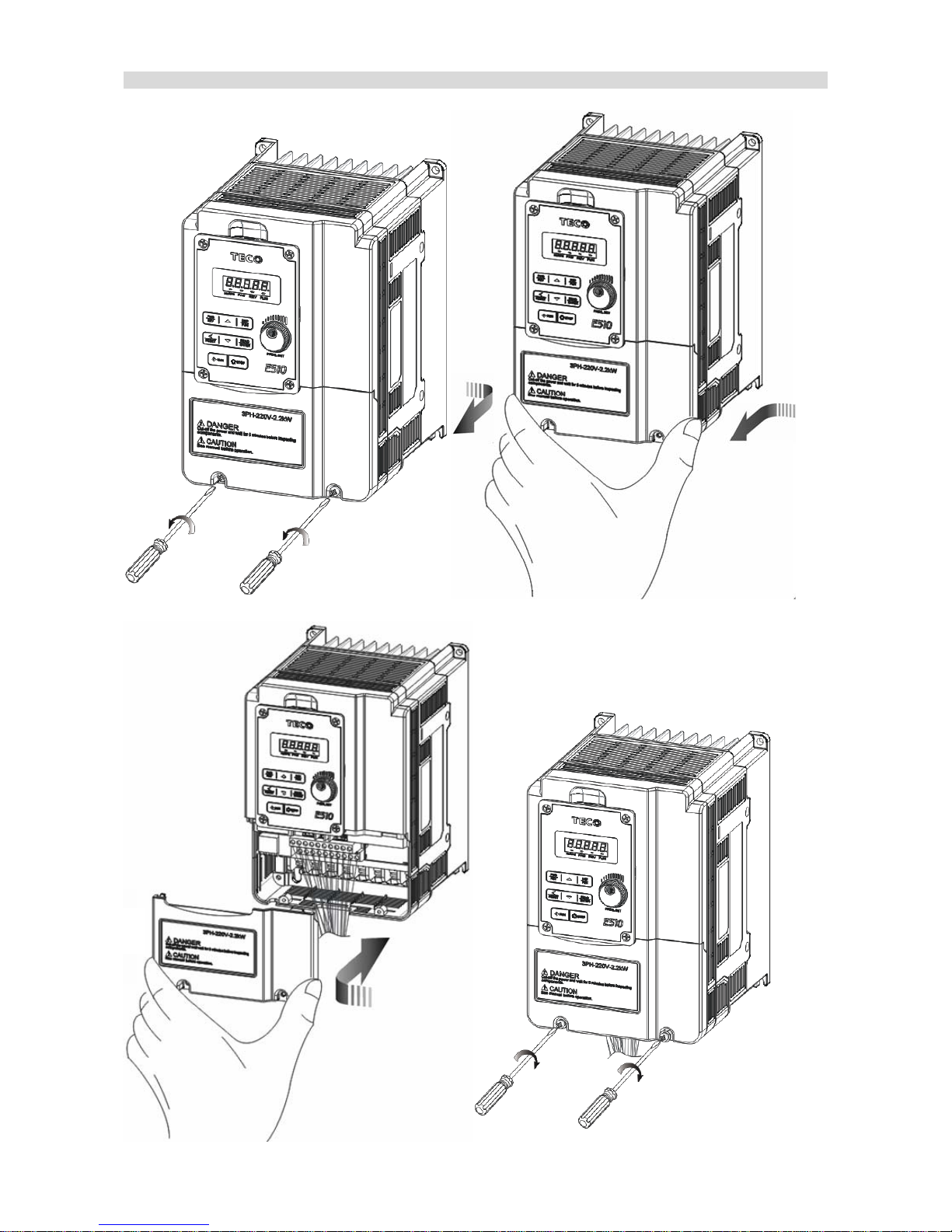
3-9
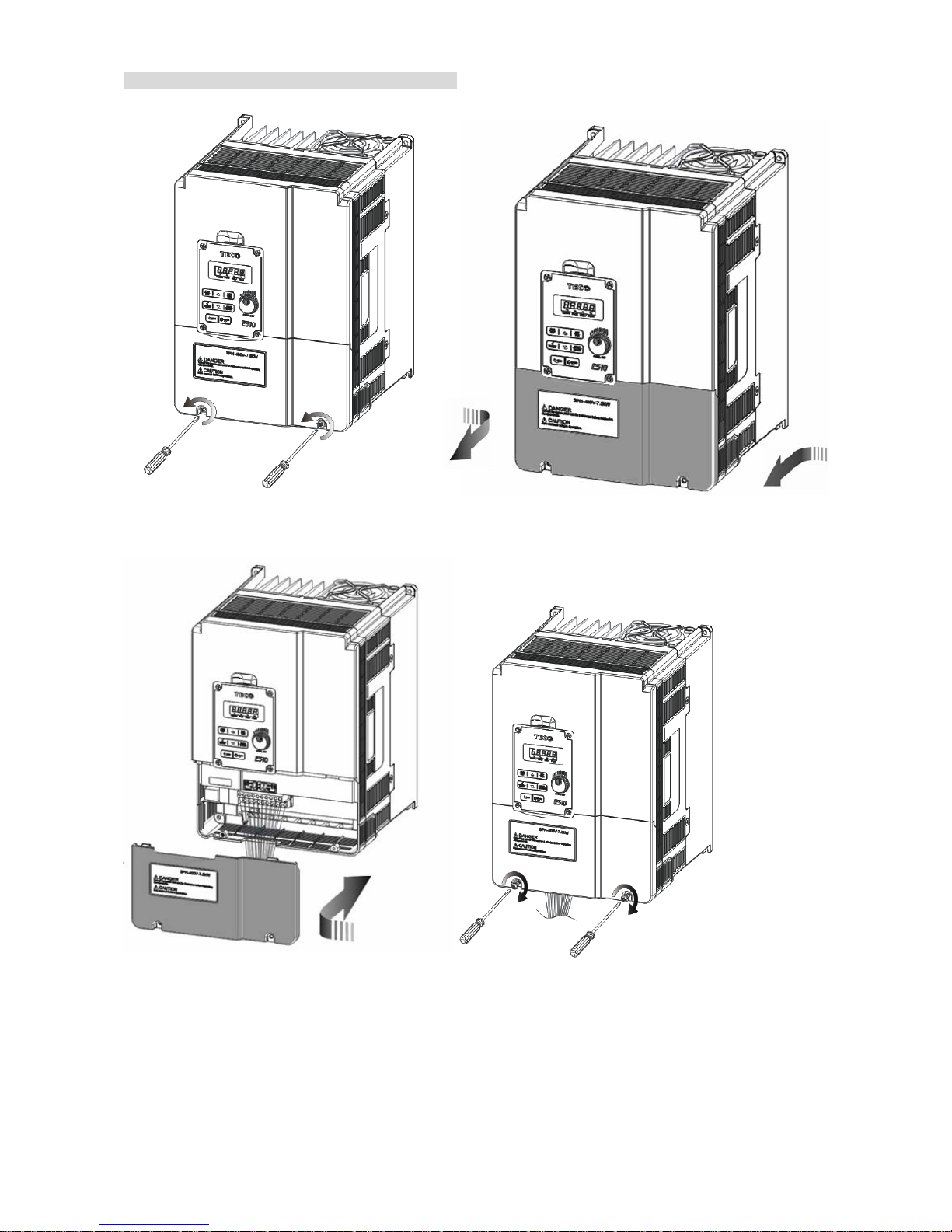
Disassembly and assembly steps, As follows:
IP20 / NEMA 1
(a)Single/Three phase: 200V 0.5~1HP; Single phase: 200V 0.5~1HP; Three phase: 200V 2HP; 400V
1~2HP;
Frame1
Step1: Loosen the screw Step2: Remove the terminal cover
Step3: Wire&Re-install the cover Step4: Tighten the screws
Page 20

3-10
Frame 1(NEMA1)
Step1: Loosen the screw Step2: Remove the terminal cover
Step3: Wire&Re-install the cover Step4: Tighten the screws
Page 21
3-11
(b)Single/Three phase: 200V 2~3HP; Single phase: 200V 2~3HP; Three phase: 200V 5HP; 400V 3~5HP;
Frame 2
Step1: Loosen the screws Step2: Remove the terminal cover
Step3: Wirie&Re-install the cover Step4: Tighten the screws
Page 22

3-12
Frame 2(NEMA1)
Step1: Loosen the screws Step2: Remove the terminal cover
Step3: Wire&Re-install the cover Step4: Tighten the screws
Page 23
3-13
(c)Three phase: 200V 7.5~10HP; 400V 7.5~15HP;
Frame 3
Step1: Loosen the screws Step2: Remove the terminal cover
Step3: Wirie&Re-install the cover Step4: Tighten the screws
Page 24

3-14
Frame 3(NEMA1)
Step1: Loosen the screws Step2: Remove the terminal cover
Step3: Wirie&Re-install the cover Step4: Tighten the screws
Page 25

3-15
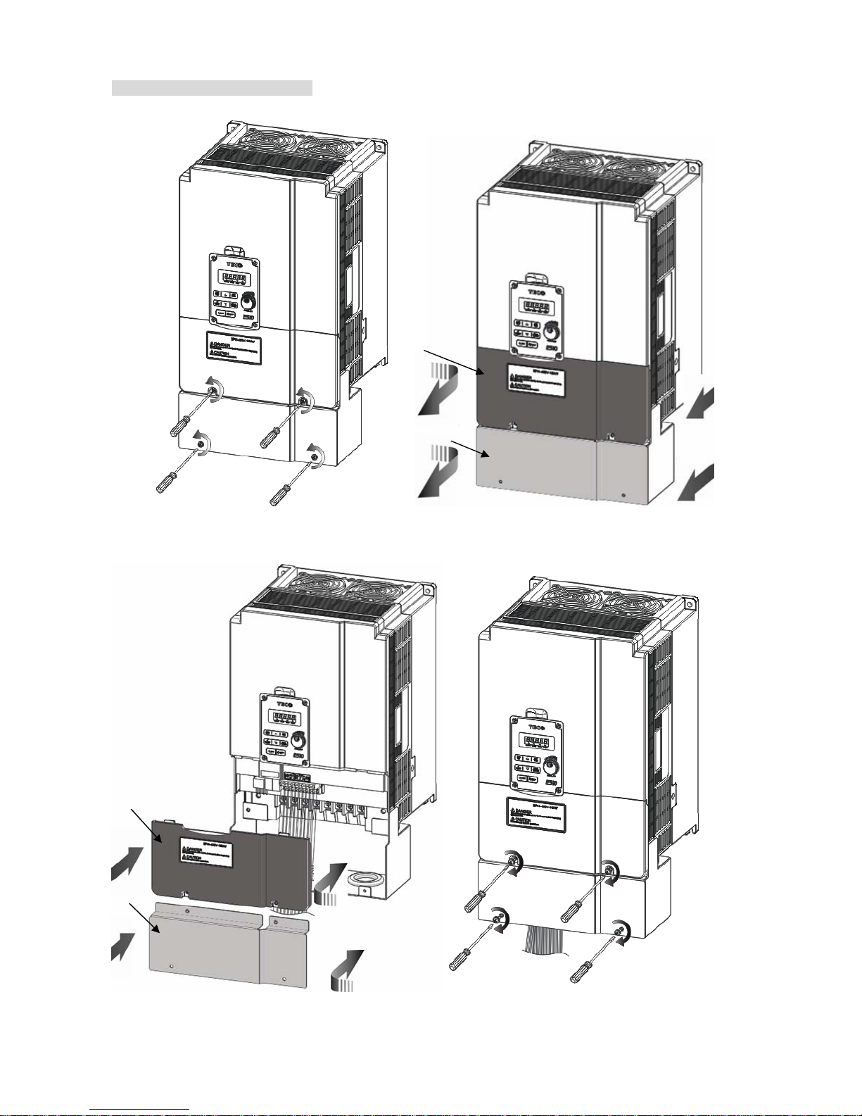
(d)Three phase: 200V 15~20HP; 400V 20~25HP;
Frame 4
Step1: Loosen the screws Step2: Remove the terminal cover
Step3: Wirie&Re-install the cover Step4: Tighten the screws
Page 26

3-16
Frame 4(NEMA1)
Step1: Loosen the screws Step2: Remove the terminal cover
Step3: Wirie&Re-install the cover Step4: Tighten the screws
Page 27
3-17
(e) Three phase: 400V 20~25HP;
Frame 4(With Filter)
Step1: Loosen the screws Step2: Remove the terminal cover
Step3: Wirie&Re-install the cover Step4: Tighten the screws
Page 28

3-18
(f) Three phase: 400V 20~25HP;
Frame 4(with filter)(E510-420-H3FPT/ E510-425-H3FPT)
Step1: Loosen the screws Step2: Remove the terminal cover
Step3: Wirie&Re-install the cover Step4: Tighten the screws
Page 29

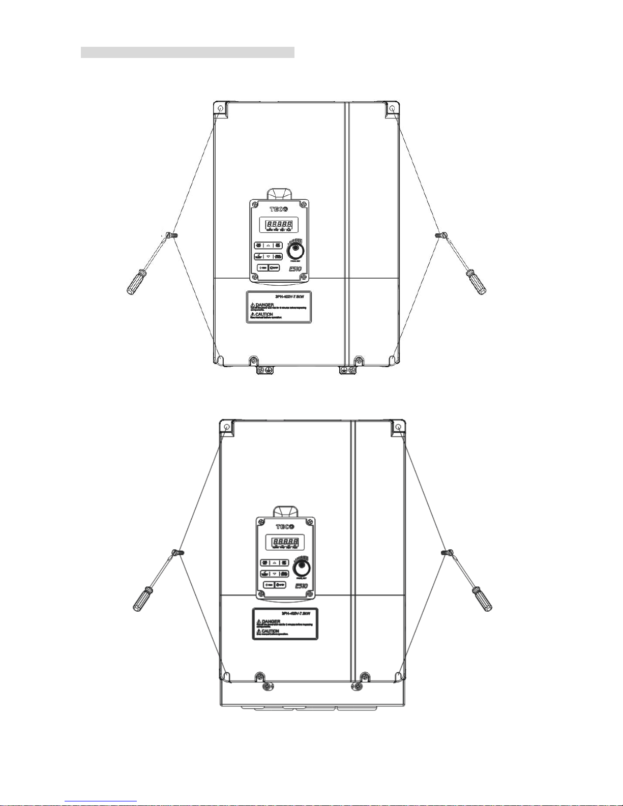
3-19
IP66/NEMA 4X
Step 1: Loosen the screws, lift and rest the cover next to the machine
Steps 2: Remove the rubber plugs and use the waterproof cable glands provided to connect
cables.
Page 30
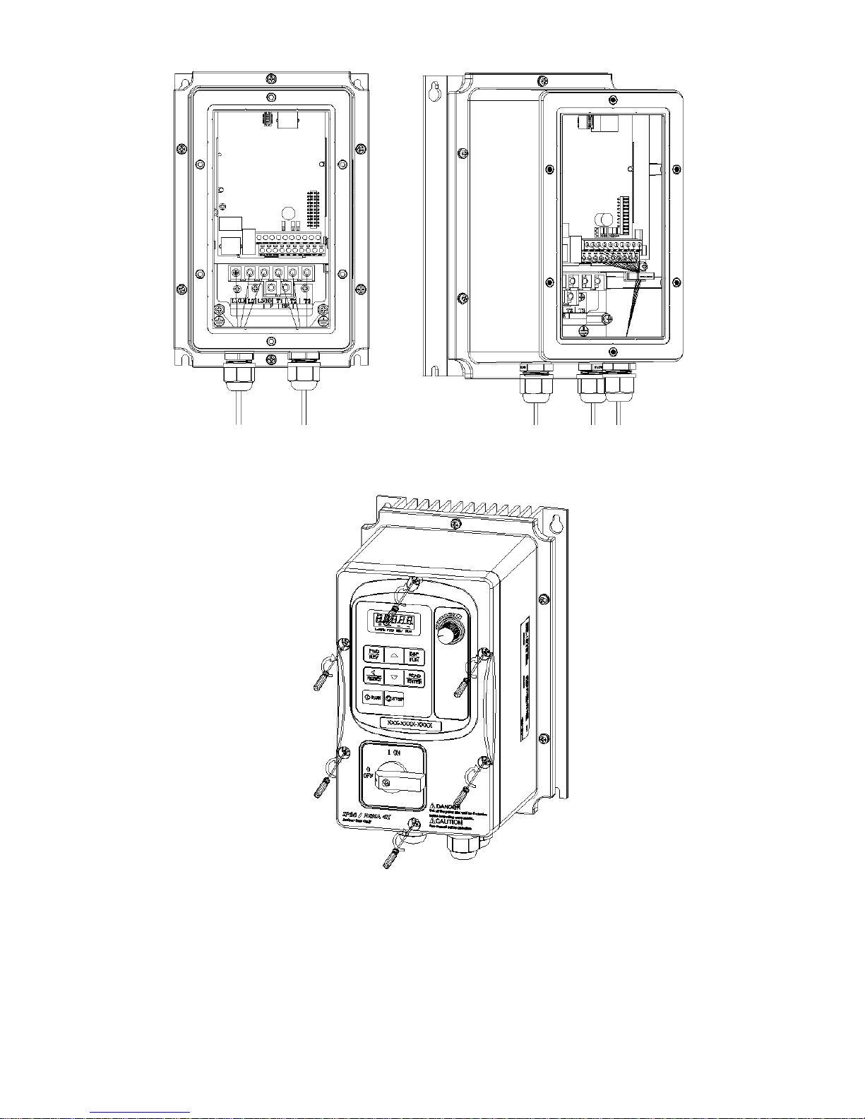
3-20
Step 3: Connect power & motor cables through the cable glands to the correct terminals.
Connect the control cable through the top gland and secure by the cable clamp.
Step 4: Ensure that the cable glands are tightened and the cover waterproof gasket is in place.
Then place the cover and tighten the screws.
Page 31

3-21
3.2.2 Installation space
Provide sufficient air circulation space for cooling as shown in examples below.
Install the Inverter on surfaces that provide good heat dissipation,
Single unit Installation
Install the inverter verticality to obtain effective cooling
Side by side Installation
Provide the necessary physical space and cooling based on the ambient temperature and the heat loss in
the panel
Front view Side view
5cm
OPERATOR
PANEL
CAUTION
DANGER
See manual before operation.
Cut-off the power and wait for 5 minutes before inspecting
components.
Hz/RPM FUNFWD REV
REV
FWD
DSP
FUN
RESET
READ
ENTER
STOPRUN
FREEQST
.
5cm
CAUTION
DANGER
See manual before operation.
Cut-off the power and wait for 5 minutes before inspecting
components.
Hz/RPM FUNFWD REV
REV
FWD
DSP
FUN
RESET
READ
ENTER
STOPRUN
FREEQST
.
CAUTION
DANGER
See manual before operation.
Cut-off the power and wait for 5 minutes before inspecting
components.
Hz/RPM FUNFWD REV
REV
FWD
DSP
FUN
RESET
READ
ENTER
STOPRUN
FREEQST
.
5cm
OPERATOR
PANEL
Fan
Extract fan
Page 32

3-22
3.2.3 De-rating curves
Curves below show the applicable output current de-rate due to setting of carrier frequency and the ambient
operating temperatures of 40 and 50 degrees C .
Frame1/2/3/4
(Single phase: 200V: 0.5~3HP; Single /Three phase: 200V: 0.5~3HP;
Three phase: 200V: 2~20HP 400V: 1~25HP)
100%
70%
85%
90%
50%
60%
2 4 6 8 10 12 14 16
Rating Current(In)
Carrier Frequency(KHz)
Note:
De-rate curve for ambient temperature of 50 degree C.
De-rate curve for ambient temperature of 40 degree C.
3.2.4 Capacitor reforming Guide after long storage
For correct performance of this product after long storage before use it is important that Inverter Capacitors
are reformed according to the guide below:
• 1 to 2 years storage: Apply 100% rated voltage for one hour.
• 2 to 3 years storage: Apply 25%, 50 % , 75% and 100% at 30 minutes intervals.
Page 33

3-23
3.3 Wiring Guidelines
3.3.1 Power Cables
Supply power cable must be connected to TM1 terminal block, terminals L1(L), L2, L3(N).
L1(L) and L3(N) for single phase 230V supply.
Motor cable must be connected to TM1 terminals. T1, T2, T3.
Warning:- Connection of supply line cable to terminals T1,T2, T3 will result in serious damage to the drive
components.
Example power connections: Inverter with dedicated power line.
Inverter IM
Power
MCCB
Install a Supply RFI filter or Isolation transformer when the power source is shared with other high power
electrical equipment as shown below.
Inverter IM
Machine
Insulation transformer
Power
MCCB
3.3.2 Control Cable selection and Wiring
Control cables should be connected to terminal block TM2.
Choose power & Control cables according to the following criteria:-
Use copper wires with correct diameter and temperature rating of 65/70°C.
Minimum cable voltage rating for 200V type inverters should be 300VAC. Minimum cable voltage rating for
400V type inverters should be 600VAC.
Route all cables away from other high voltage or high current power lines to reduce interference effects.
Use a twisted pair shielded cable and connect the shield (screen) wire to the ground terminal at the
inverter end only. Cable length should not exceed 50 meters.
Shielding sheath
Protective covering
Connect the shield to
Inverter ground terminal
Do not connect this end
Inverter IM
Machine
RFI
Filter
Power
MCCB
Page 34

3-24
3.3.3 Wiring and EMC guidelines
For effective interference suppression, do not route power and control cables in the same conduit or
trunking.
To prevent radiated noise, motor cable should be put in a metal Conduit. Alternatively an armored or shielded
type motor cable should be used.
For effective suppression of noise emissions the cable armor or shield must be grounded at both ends to the
motor and the inverter ground. These connections should be as short as possible.
Motor cable and signal lines of other control equipment should be at the least 30 cm apart.
E510 has a built in Class “A” EMC filter to first Environment Restricted. (Category C2).
Typical Wiring.
1.Protective Earth Conductor.
Conductor size for enclosure &
Back plate must comply with the local
electrical standards. Min 10mm².
2.Back plate. Galvanised steel (Unpainted).
3.Ferrite core / Output reactor
ferrite cores can be used to reduce
radiated noise due to long motor cables.
If ferrite core is used loop motor wires, 3
times round the core. Install core as close
to the inverter as possible
Output reactors provide additional
benefit of reducing dv/dt for protection of
motor windings.
4.Metal Cable clamp. no more than 150mm
from the inverter.
Note: If no enclosure & back plate is
used then connect the cable shield by a
good 360 degree termination to the
Inverter output terminal E.
5.Screened (Shielded four core cable).
6.Separate Protective Earth wire, routed
outside motor cable separated be at least
100mm.
Note:- this is the preferred method
specially for large output cables and long
length.
Multi-core screened (3 core & protective
earth) can be used for small power and
short length.
7.Connect the cable shield by a good
360º termination and connect to the motor
protective earth terminal.
This link must be as short as possible.
8.Motor Earth terminal(Protective Earth).
L1(L)
L3(N)
L1(L)
L3(N)
E
Page 35

3-25
3.3.4 Failure liability
Teco bears no responsibility for any failures or damaged caused to the inverter if the recommendations
in this instruction manual have not been followed specifically points listed below,
If a correctly rated Fuse or Circuit breaker has not been installed between the power source and the
inverter.
If a magnetic contactor, a phase capacitor, burst absorber and LC or RC circuits have been connected
between the inverter and the motor.
If an incorrectly rated three-phase squirrel cage induction motor has been used
When one inverter is driving several motors, the total current of all motors running simultaneously must
be less than the rated current of the inverter, and each motor has to be equipped with a correctly rated
thermal overload relay.
“Only Intended For Use In A Pollution Degree 2 Environment” or equivalent.
Since there is no over speed protection there will be no liablity due to overspeed damage.
Page 36

3-26
3.3.5 Considerations for peripheral equipment
(
Power
Ensure that the supply voltage is correct.
A molded-case circuit breaker or fused disconnect
must be installed between the AC source and the
inverter
Circuit
Breaker
& RCD
Use a molded-case circuit breaker that conforms
to the rated voltage and current of the inverter.
Do not use the circuit breaker as the run/stop
switch for the inverter.
Residual Current Circuit Breaker(RCD)
Current setting should be 200mA or above and the
operating time at 0.1 second or longer to prevent
malfunctions.
Magnetic
contactor
Normally a magnetic contactor is not needed.
A contactor can be used to perform functions such
as external control and auto restart after power
failure.
Do not use the magnetic contactor as the run/stop
switch of the inverter.
AC reactor for
power quality
improvement
When a 200V/400V inverter with rating below
15KW is connected to a high capacity power
source (600KVA or above) then an AC reactor can
be connected for power factor improvement and
reducing harmonics.
Input noise
filter
E510 has a built-in filter (Class A/First
Environment Category C2, except for Frame 4)
To satisfy the required EMC regulations for your
specific application you may require an additional
EMC filter.
Inverter
Connect the single phase power to Terminals,
L1(L) & L3(N).
Warning! Connecting the input terminals T1, T2,
and T3 to AC input power will damage the inverter.
Output terminals T1, T2, and T3 are connected to
U, V, and W terminals of the motor.
To reverse the motor rotation direction just swap
any two wires at terminals T1, T2, and T3.
Ground the Inverter and motor correctly.
Ground Resistance for 200V power<100 Ohms.
Ground Resistance for 400V power<10 Ohms
Motor
Three-phase induction motor. Voltage drop on
motor due to long cable can be calculated.
Volts drop should be < 10%.
Phase-to-phase voltage drop (V) =
3 ×resistance of wire (Ω/km)×length of
line(m)×current×10
-3
Grounding
Page 37

3-27
3.3.6 Ground connection
Inverter ground terminal must be connected to installation ground correctly and
according to the required local wiring regulations.
Ground cable size must be according to the required local wiring
regulations. Ground connection should be as short as possible.
Do not share the ground of the inverter with other high current loads (Welding machine, high power
motors). Ground each unit separately.
Ensure that all ground terminals and connections are secure
Do not make ground loops when several inverters share a common ground point.
Note: Please leave at least 5cm while installing inverter side by side in order to provide enough
cooling
space.
(a) Correct (b) Correct (c) Incorrect
Page 38

3-28
3.3.7 Inverter exterior
3.3.7.1 IP20/NEMA 1 exterior
(a) Single/Three phase: 200V 0.5~1HP; Single phase: 200V 0.5~1HP; Three phase: 200V
2HP; 400V 1~2HP;
E510-Frame 1
E510-Frame 1(NEMA1)
Page 39

3-29
(b) Single/Three phase: 200V 2~3HP; Single phase: 200V 2~3HP; Three phase: 200V 5HP;
400V 3~5HP;
E510-Frame2
E510-Frame2(NEMA1)
Page 40

3-30
(c) Three phase: 200V 7.5~10HP; 400V 7.5~15HP;
E510-Frame 3
E510-Frame 3(NEMA1)
Page 41

3-31
(d) Three phase: 200V 15~20HP; 400V 20~25HP;
E510-Frame 4
E510-Frame 4(NEMA1)
Page 42

3-32
(e) Three phase: 400V 20~25HP;
E510-Frame 4 (With Filter)
(f) Three phase: 400V 20~25HP;
Frame 4(with filter)(E510-420-H3FPT/ E510-425-H3FPT)
Fan cover
Installation
holes
Heat sink
Name plate
label
Bar-code
label
Down cover
Distributing box
Operator Panel
Over cover
Warning label
Terminal cover
Installation
holes
Heat sink
Name plate
label
Bar-code label
Distributing box
Down cover
Operator Panel
Over cover
Warning label
Terminal cover
Page 43

3-33
3.3.7.2 IP66/NEMA 4X exterior
(a) Single/Three phase : 200V 0.5~1HP ; Single phase : 200V 0.5~1HP ; Three phase : 200V
2HP ; 400V 1~2HP
E510-Frame 1(IP66/NEMA 4X With/Without VR and power switches depending on the model)
Mounting hole
Heat sink
VR
Mounting hole
Power switch
Front cover
5-digit Display
Operator panel
Screw
Name plate label
Bottom cover
Model label
waterproof cable
gland
Page 44

3-34
(b) Single/Three phase : 200V 2~3HP ; Single phase : 200V 2~3HP;Three phase : 200V5HP ;
400V 3~5HP
E510-Frame 2 (IP66/NEMA 4X With/Without VR and switches depending on the model)
(c) Three phase : 200V 8~20HP ; 400V 8~25HP
E510-Frame 3 (IP66/NEMA 4X With/Without VR and switches depending on the model)
Heat sink
Mounting hole
VR
Power switch
Front cover
5-digit Display
Operator panel
Screw
Bottom cover
Model label
waterproof cable
gland
Mounting hole
Heat sink
VR
Power switch
Front cover
5-digit Display
Operator panel
Screw
Bottom cover
Model label
waterproof cable
gland
Page 45

3-35
Interior Layout
E510-Frame 1 E510-Frame 2
E510-Frame 3 E510-Frame 4
RS485
400V 5.5kW
RS485
400V 15kW
Ground terminal
TM1
TM2
Operator panel
Operator panel
TM2
TM1
Ground
termina
RS485
400V 3.7kW
200V 0.75kW
RS485
Page 46

3-36
Warning label
Page 47

3-37
3.4 Specifications
3.4.1 Product Specifications
200V Class:Single phase
Model:E510-□□□- H1F(N4)(S) 2P5 201 202 203
Horse power (HP)
0.5 1 2 3
Suitable motor capacity (KW)
0.4 0.75 1.5 2.2
Rated output current (A)
3.1 4.5 7.5 10.5
Rated capacity (KVA)
1.2 1.7 2.90 4.00
Input voltage range(V)
Single Phase:200~240V,50/60HZ
Allowable voltage fluctuation
+10%-15%
Output voltage range(V)
Three phase: 0~240V
Input current (A)*
8.5 12 16 23.9
Inverter net weight (KG)
1.65 1.65 2.5 2.5
Allowable momentary power loss time (S)
2.0 2.0 2.0 2.0
Enclosure
IP20/NEMA1&IP66/NEMA4X
200V Class:Single/Three phase
Model:E510-□□□- H(N4R) 2P5 201 202 203
Horse power (HP)
0.5 1 2 3
Suitable motor capacity (KW)
0.4 0.75 1.5 2.2
Rated output current (A)
3.1 4.5 7.5 10.5
Rated capacity (KVA)
1.2 1.7 2.90 4.00
Input voltage range(V)
Single/Three Phase:200~240V, 50/60HZ
Allowable voltage fluctuation
+10%-15%
Output voltage range(V)
Three phase: 0~240V
Input current (A)*
8.5/4.5 12/6.5 16/11 23.9/12.5
Inverter net weight (KG)
1.6 1.6 2.5 2.5
Allowable momentary power loss time (S)
2.0 2.0 2.0 2.0
Enclosure
IP20/NEMA1&IP66/NEMA4X
200VClass:Three phase
Model: E510-□□□- H3(N4) 202 205 208 210 215 220
Horse power (HP)
2 5 7.5 10 15 20
Suitable motor capacity (KW)
1.5 3.7 5.5 7.5 11 15
Rated output current (A)
7.5 17.5 26 35 48 64
Rated capacity (KVA)
2.9 6.7 9.9 13.3 20.6 27.4
Input voltage range(V)
Three phase :200~240V,50/60HZ
Allowable voltage fluctuation
+10%-15%
Output voltage range(V)
Three phase: 0~240V
Input current (A)*
11 20.5 33 42 57 70
Inverter net weight (KG)
1.6 2.5 6.5 6.5 10.1 10.4
Allowable momentary power loss time (S)
2.0 2.0 2.0 2.0 2.0 2.0
Enclosure
IP20/NEMA1&IP66/NEMA4X
*The input current is calculated value at full rated output current.
Page 48

3-38
400VClass:Three phase
Model:E510-□□□- H3(F)(N4)(S) 401 402 403 405
Horse power (HP)
1 2 3 5
Suitable motor capacity (KW)
0.75 1.5 2.2 3.7
Rated output current (A)
2.3 3.8 5.2 8.8
Rated capacity (KVA)
1.7 2.9 4.0 6.7
Input voltage range(V)
Three phase:380~480V,50/60HZ
Allowable voltage fluctuation
+10%-15%
Output voltage range(V)
Three phase:0~48 0 V
Input current (A)*
4.2 5.6 7.3 11.6
Inverter net weight (KG)
1.7 1.7 2.5 2.5
Allowable momentary power loss time (S)
2.0 2.0 2.0 2.0
Enclosure
IP20/NEMA1&IP66/NEMA4X
Model:E510-□□□H3(F)(N4)(S)
408 410 415 420 425
Horse power (HP)
7.5 10 15 20 25
Suitable motor capacity (KW)
5.5 7.5 11 15 18.5
Rated output current (A)
13.0 17.5 24 32 40
Rated capacity (KVA)
9.9 13.3 19.1 24 30.5
Input voltage range(V)
Three phase:380~480V,50/60HZ
Allowable voltage fluctuation
+10%-15%
Output voltage range(V)
Three phase: 0~48 0 V
Input current (A)*
17 23 31 38 48
Inverter net weight (KG)
6.7 6.7 6.7 13.7 13.7
Allowable momentary power loss time
(S)
2.0 2.0 2.0 2.0 2.0
Enclosure
IP20/NEMA1&IP66/NEMA4X
*The input current is calculated value at full rated output current.
*N4S 400V series only up to 15HP.
F: Built-in filter
N4: Protection class IP66, without built-in power switches and VR.
N4R: Protection class IP66, with built-in VR, without power switches
N4S: Protection class IP66, with built-in power switches and VR
PT: footprint type filter
Model: E510-□□□- H3(F)(PT) 420 425
Horse power (HP)
20 25
Suitable motor capacity (KW)
15 18.5
Rated output current (A)
32 40
Rated capacity (KVA)
24 30.5
Input voltage range(V)
three phase:380~ 480V (+10%-15%),50/60HZ
Output voltage range(V)
three phase: 0~ 480V
Input current (A)*
38 48
Allowable momentary power loss time (S)
2.0 2.0
Enclosure
IP20
Page 49

3-39
3.4.2 General Specifications
Item
E510
Control Mode
V/F Control, Vector Control
Frequency
Output Frequency 0.01~599.00Hz
Starting Torque 150%/1Hz(Vector)
Speed Control Range 1:50
Setting resolution
Digital input: 0.01Hz
Analog input:0.06Hz/60Hz
Setting
Keypad:Set directly with▲▼ keys or the VR on the
keypad
External Input Terminlas:
AI1(0/2~10V), AI2(0/4~20mA)input
Multifunction input up/down function(Group3)
Setting frequency by communication method.
Frequency limit
Lower and upper frequency limits
3 skip frequency settings.
Run
Operation set
Keypad run, stop button
External terminals:
Multi- operation-mode2 / 3 wire selection
Jog operation
Run signal by communication method.
Main Control
Features
V / F curve setting 18 fixed curves and one customized curve
Carrier frequency 1~16KHz
Acceleration and
deceleration control
2 off Acc / dec time parameters.
4 off S curve parameters.
Multifunction input 29 functions (refer to description on group3)
Multifunction output 21 functions (refer to description on group3)
Multifunction analog
output
5 functions (refer to description on group4)
Main features
Overload Detection,16 preset speeds,Auto-run,Acc/Dec
Switch (2 Stages),Main/Alt run Command select,Main/Alt
Frequency Command select,PID control, torque boost, V/F
start Frequency, Fault reset, Firemode.
Display
LED
Display :parameter / parameter value / frequency / line
speed / DC voltage / output voltage / output current / PID
feedback / input and output terminal status / Heat sink
temperature / Program Version / Fault Log.
LED Status Indicator Run / Stop / Forward / Reverse ,and etc.
Protective
Functions
Overload Protection
The relays to protect the motor and the inverter.
(150%/1min)
Over voltage ·220V: >410V ,380V: >820V
Under Voltage ·220V: <190V , 380V: <380V
Momentary Power Loss
Restart
Inverter auto-restart after a momentary power loss.
Stall Prevention
Stall prevention for Acceleration/ Deceleration/ Operation.
Short-circuit output
terminal
Electronic Circuit Protection
Grounding Fault Electronic Circuit Protection
Other protection features
Protection for overheating of heat sink,The carrier
frequency decreasing with the temperature function,fault
output,reverse prohibit,prohibit for direct start after power
up and error recovery ,parameter lock up
Page 50

3-40
All frames include brake transistor
Communication control
Standard built-in RS485 communication (Modbus), One to
one or One to many control.
Environment
Operating temperature
-10~50℃ (Note1)
Storage temperature
-20~60℃
Humidity
95% RH or less (no condensation)
(Compliance with IEC 60068 - 2-78)
Shock
20Hz or less 1G(9.8m/s²)20~50Hz 0.6G(5.88m/s²)
(Compliance with IEC 60068 - 2-6)
Enclosure IP20/NEMA1& IP66/NEMA4X
Note1:
IP20/NEMA 1 Type:
–10 ~ 50℃ (without stick on type dust cover.)
–10 ~ 40℃ (with stick on type dust cover.)
IP66/NEMA 4X Type :
-10~50°C
Page 51

3-41
3.5 Standard wiring
3.5.1 Single phase
External speed
potentiometer = 10 Kohm
or PID input
Frequency
Indicator
+
T1
10V
AI1
AI2
AGND
0 ~10V
M
0~20mA
-
Inverter
output
Induction
Motor
S3
S4
S5
S6
S2
FWD
(Run/Stop)
S1
R2B
250 VAC/1A
(30VDC/1A)
Relay
Output
Relay
Output
RS485
CON2
AO
AGND
+
-
0~10VDC
NPN
PNP
AI1 AI2
AV1
AV2
J
P
1
Ground
REV (Run/Stop)
250 VAC/1A
(30VDC/1A)
R2A
R1A
R1B
R1C
T2
T3
J
P
2
J
P
3
P
BR
Braking resistor
(Option)
+ 24V(PNP)
COM (NPN)
Output disable
SG
SF
AO
Speed Control
Multifunction Input Terminals
E
E
E
P
P
Pin 1 to Pin 8
Reset
Indicates twisted-pair shield wire
P
Shows control circuit
Shows main circuit
Indicates shield wire
*1: JP1:NPN/PNP selection, JP2:AI1 0~10V/0~20mA selection, JP3:AI2 0~10V/0~20mA selection
*1
1:Data+
2:Data3:Data+
4:RXD0
5:TXD0
6:Data7:5V
8:GND
AC Power
source
L1(L)
Fuse
Main
Switch
Power
input
L3(N)
E
Model:
200V: E510-2P5-H1(F)(N4S) /E510-201-H1(F)(N4S)/ E510-202-H1(F)(N4S) /E510-203-H1(F)(N4S)
Page 52

3-42
3.5.2 Single /Three phase
Model:
200V: E510-2P5-H(N4R)/ E510-201-H(N4R)/ E510-202-H(N4R)/ E510-203-H(N4R)
Page 53

3-43
3.5.3 Three phase
External speed
potentiometer = 10 Kohm
or PID input
Frequency
Indicator
+
T1
10V
AI1
AI2
AGND
0 ~10V
M
0~20mA
-
Inverter
output
Induction
Motor
S3
S4
S5
S6
S2
FWD
(Run/Stop)
S1
R2B
250 VAC/1A
(30VDC/1A)
Relay
Output
Relay
Output
RS485
CON2
AO
AGND
+
-
0~10VDC
NPN
PNP
AI1 AI2
AV1
AV2
J
P
1
Ground
REV (Run/Stop)
250 VAC/1A
(30VDC/1A)
R2A
R1A
R1B
R1C
T2
T3
J
P
2
J
P
3
P
BR
Braking resistor
(Option)
Output Disable
SG
SF
AO
Speed Control
Multifunction Input Terminals
E
E
E
P
P
Pin 1 to Pin 8
Reset
*1
1:Data+
2:Data3:Data+
4:RXD0
5:TXD0
6:Data7:5V
8:GND
+ 24V(PNP)
COM (NPN)
Indicates twisted-pair shield wire
P
Shows control circuit
Shows main circuit
Indicates shield wire
*1: JP1:NPN/PNP selection, JP2:AI1 0~10V/0~20mA selection, JP3:AI2 0~10V/0~20mA selection
AC Power
source
L1
Fuse
Main
Switch
Power
input
L3
L2
E
Model:
200V:E510-202-H3(N4)/E510-205-H3(N4)/E510-208-H3(N4)/E510-210-H3(N4)/
E510-215-H3(N4)/E510-220-H3(N4)
400V:E510-401-H3(F)(N4)(S)/ E510-402-H3(F)(N4)(S)/ E510-403-H3(F)(N4)(S)/ E510-405-H3(F)(N4)(S)/
E510-408-H3(F)(N4)(S)/ E510-410-H3(F)(N4)(S)/ E510-415-H3(F)(N4)(S)/ E510-420-H3(F)(N4)/
E510-425-H3(F)(N4)/ E510-420-H3FPT/E510-425-H3FPT
Page 54

3-44
3.6 Terminal Description
3.6.1 Description of main circuit terminals
Terminal symbols TM1 Function Description
L1(L)
Main power input: Single phase: L1(L)/L3(N)
Single/Three phase:L1(L)/L2/L3(N)
Three phase:L1/L2/L3
L2
L3(N)
T1
Inverter output, connect to U/V/W terminals of motor
T2
T3
P
Braking resistor connection terminal: Used in applications when it is required to stop a
high inertia load rapidly. (refer to specifications of the braking resistor)
BR
Ground terminal
Frame1
Single phase: 200V 0.5~1HP
Note: the screw on L2 terminal is removed for the single phase input supply models.
Single/Three phase:200V 0.5~1HP; Three phase:200V 2HP; 400V 1~2HP;
L1(L) L2 L3(N) T1 T2 T3
P
BR
L1(L) L2 L3(N) T1 T2 T3
P
BR
Page 55

3-45
Frame2
Single phase:200V 2~3HP;
Single/Three phase:200V 2~3HP; Three phase:200V 5HP; 400V 3~5HP;
Frame3 & Frame4
Three phase:200V 7.5~20HP; 400V 7.5~25HP
L1(L) L2 L3(N) P BR T1 T2 T3
L1(L) L2 L3(N) P BR T1 T2 T3
L1 L2 L3 P BR T1 T2 T3
Page 56

3-46
3.6.2 Control circuit terminal description
Type Terminal Terminal function Signal level
Digital
input
signal
S1 Forward─Stop (Preset), Multi function input terminal
24 VDC, 8 mA, Optical
coupling
isolation(Max,voltage30 Vdc,
Input impedance 3.3kΩ)
S2 Reverse─Stop (Preset), Multi function input terminal
S3 Preset Speed0(5-02),Multi function input terminal
S4 Preset Speed1(5-03), Multi function input terminal
S5 Preset Speed2(5-05), Multi function input terminal
S6 Fault reset input, Multi function input terminal
Relay
output
R1A
NO(Normally
open)
Multi function output:Run,Fault,setting
Frequency ,Frequency Reached,Auto
Restart,Momentary AC Power Loss,Rapid
Stop ,Base Block Stop Mode,Motor Overload
Protection,Drive Overload
Protection,Over-torque Threshold Level、
Preset Current level Reached、Preset Brake
Frequency Reached,PID Feedback Signal
Loss,Final count value reached, Initial count
value recahed,PLC Status Indicator ,PLC
control…
250VAC/1A(30VDC/1A)
R1B
NC(Normally
closed)
R1C COMMON
R2A
R2B
24VPower
supply
COM
Digital signal common terminal (JP1 Switching NPN
position)
±15%,Max output current
60mA
24V Digital signal common terminal (JP1 Switching PNP position)
The
analog
input
signal
10V Built in Power for an external speed potentiometer 10V(Max current:20mA)
AI1
Multifunctional analog input: JP2 selects voltage or current
input
Voltage: JP2 in AV1 position
Current: JP2 in AI1 position
0 ~ 10V,(Max current:20mA)
(Input impedance: 153KΩ)
AI2
Multifunctional analog input: JP3 selects voltage or current
input
Voltage: JP3 in AV2 position
Current: JP3 in AI2 position
0 ~ 10V,0 ~20mA
(Input impedance: 153KΩ)
AGND The analog common terminal ----
Shielding wire connecting terminal (The earth) ----
The
analog
onput
signal
AO Multifunctional analog output terminal*3 0 ~10V,(Max current:2mA)
AGND The analog common terminal ----
Safety
switch
SF
Terminal SF is for output disable
SG
Control circuit terminal:
Page 57

3-47
JUMPER function description
Jumper Symbol Function Signal Reference Note
JP1
NPN/PNP selectable
NPN Input
Factory defult setting
PNP Input
JP2/JP3
External signal type
selection
0~20mA / 4~20mA
Analog signal
Set parameters
00-05/00-06
to 2 or 3 (external analog
input) to become
effective
0~10VDC / 2~10VDC
Analog signal
Page 58

3-48
3.7 Outline Dimensions mm(inch)
Tolerance Table
1 ~ 100.1
(0.04~0.40
0.004)
10 ~ 50
0.2
(0.40~1.97
0.01)
50 ~ 100
0.3
(1.97~4
0.01)
100 ~ 200
0.5
(4~7.87
0.02)
200 ~ 400
0.8
(7.87~15.75
0.03)
3.7.1 IP20/NEMA1 dimensions
Frame1 (IP20)
Single/Three phase: 200V 0.5~1HP ; Single phase: 200V 0.5~1HP
Three phase: 200V 2HP; 400V 1~2HP
2-Q1
2-Q2
W1
H1
H
W2
W
E
D
D1
Unit: mm(inch)
Model
Dimensions
N.W
(Kg)
W W1 W2 H H1 D D1 E Q1 Q2
E510-2P5-H
90.6
(3.57)
80.5
(3.17)
80.5
(3.17)
163.6
(6.44)
153
(6.02)
149
(5.87)
137.8
(5.43)
48
(1.89)
4.3
(0.17)
4.3
(0.17)
1.6
E510-201-H 1.6
E510-2P5-H1F 1.7
E510-201-H1F 1.7
E510-202-H3 1.7
E510-401-H3 1.7
E510-402-H3 1.7
E510-401-H3F 1.7
E510-402-H3F 1.7
Page 59

3-49
Frame2 (IP20)
Single/Three phase: 200V 2~3HP ; Single phase: 200V 2~3HP
Three phase: 200V 5HP; 400V 3~5HP
W1
H1
H2
W2
W
2-Q1
E
D1
D
D2
2-Q2
H
Unit: mm(inch)
Model
Dimensions
N.W
(Kg)
W W1 W2 H H1 H2 D D1 D2 E Q1 Q2
E510-202-H
128.7
(5.07)
118
(4.65)
118
(4.65)
187.6
(7.39)
177.6
(6.99)
197.5
(7.78)
150
(5.91)
133.8
(5.27)
141.8
(5.58)
48.2
(1.9)
4.5
(0.18)
4.5
(0.18)
2.5
E510-203-H 2.5
E510-202-H1F 2.5
E510-203-H1F 2.5
E510-205-H3 2.5
E510-403-H3 2.5
E510-405-H3 2.5
E510-403-H3F 2.5
E510-405-H3F 2.5
Page 60

3-50
Frame3 (IP20)
Three phase: 200V 7.5~10HP; 400V 7.5~15HP
W1
H
W
D
D1
D2
E
W2
H2
2-Q1
H1
2-Q2
Unit: mm(inch)
Model
Dimensions
N.W
(Kg)
W W1 W2 H H1 H2 D D1 D2 E Q1 Q2
E510-208-H3
186.9
(7.36)
175
(6.89)
176
(6.93)
260.9
(10.27)
249.8
(9.83)
273
(10.75)
197.2
(7.76)
184
(7.24)
189
(7.44)
76.7
(3.02)
4.5
(0.18)
4.5
(0.18)
6.5
E510-210-H3 6.5
E510-408-H3 6.5
E510-410-H3 6.5
E510-415-H3 6.5
E510-408-H3F 6.7
E510-410-H3F 6.7
E510-415-H3F 6.7
Page 61

3-51
Frame4 (IP20)
Three phase: 200V 15~20HP; 400V 20~25HP
D1
D
D2
E
2-Q1
2-Q2
H1
H2
W2
W
H
W1
Unit: mm(inch)
Model
Dimensions
N.W
(Kg)
W W1 W2 H H1 H2 D D1 D2 E Q1 Q2
E510-215-H3
224.6
(8.84)
207
(8.15)
207
(8.15)
321.6
(12.66)
303.5
(11.95)
330.9
(13.03)
200.7
(7.9)
187.5
(7.38)
192.5
(7.58)
94
(3.7)
6
(0.24)
6
(0.24)
10.1
E510-220-H3 10.4
E510-420-H3 10.5
E510-425-H3 10.5
Page 62

3-52
Frame4 (IP20) (With Filter)
Three phase: 400V 20~25HP
Unit: mm(inch)
Model
Dimensions
N.W
(Kg)
W W1 W2 H H1 H2 D D1 D2 E1 E2 Q1 Q2
E510-420-H3F
224.6
(8.84)
207
(8.15)
207
(8.15)
436
(17.17)
303.5
(11.95)
330.9
(13.03)
200.7
(7.9)
187.5
(7.38)
192.5
(7.58)
64
(2.52)
192.5
(7.58)
6
(0.24)
6
(0.24)
13.7
E510-425-H3F 13.7
Page 63

3-53
Frame4 (IP20) (With Filter)
Three phase: 400V 20~25HP
W1
H
W E1
E
D2
D
D1
2-Q
H1
Unit: mm(inch)
Model
Dimensions
N.W
(Kg)
W W1 H H1 D D1 D2 E E1 Q
E510-420-H3FPT
235.6
(9.28)
180
(7.09)
400
(15.75)
381.5
(15.02)
263
(10.35)
249.5
(9.82)
254.5
(10.02)
62
(2.44)
237
(9.33) 7 (0.28)
13.8
E510-425-H3FPT 13.8
Page 64

3-54
Frame1 (NEMA1)
Single/Three phase: 200V 0.5~1HP; Single: 200V 0.5~1HP
Three phase: 200V 2HP; 400V 1~2HP
W1
W
H
H1
D
D1
D2
E
E1
2-Q
Unit: mm(inch)
Model
Dimensions
N.W
(Kg)
W W1 H H1 D D1 D2 E E1 Q
E510-2P5-H
90.6
(3.57)
80.5
(3.17)
186.2
(7.33)
189.2
(7.45)
149
(5.87)
137.8
(5.42)
141
(5.55)
41.2
(1.62)
120.5
(4.74)
4.33
(0.17)
1.8
E510-201-H 1.8
E510-2P5-H1F 1.9
E510-201-H1F 1.9
E510-202-H3 1.9
E510-401-H3 1.9
E510-402-H3 1.9
E510-401-H3F 1.9
E510-402-H3F 1.9
Page 65

3-55
Frame2 (NEMA1)
Single/Three phase: 200V 2~3HP; Single: 200V 2~3HP
Three phase: 200V 5HP; 400V 3~5HP
W1
W
H
H1
E1
E
D
D1
D2
2-Q
Unit: mm(inch)
Model
Dimensions
N.W
(Kg)
W W1 H H1 D D1 D2 E E1 Q
E510-202-H
128.7
(5.06)
118
(4.65)
210.6
(8.29)
213.6
(8.41)
150(5.91)
133.8
(5.27)
141.8
(5.58)
46.1
(1.81)
121.1
(4.77)
4.5
(0.18)
2.7
E510-203-H 2.7
E510-202-H1F 2.8
E510-203-H1F 2.8
E510-205-H3 2.8
E510-403-H3 2.8
E510-405-H3 2.8
E510-403-H3F 2.8
E510-405-H3F 2.8
Page 66

3-56
Frame3 (NEMA1)
Three phase: 200V 7.5~10HP; 400V 7.5~15HP
W1
H
W
D
D1
D2
E
H1
2-Q
E1
Unit: mm(inch)
Model
Dimensions
N.W
(Kg)
W W1 H H1 D D1 D2 E E1 Q
E510-208-H3
187.5
(7.38)
176
(6.92)
291
(11.47)
293.5
(11.56)
197
(7.76)
184
(7.24)
189
(7.44)
76.7
(3.02)
170.6
(6.72)
4.5
(0.18)
6.9
E510-210-H3 6.9
E510-408-H3 6.9
E510-410-H3 6.9
E510-415-H3 6.9
E510-408-H3F 7.1
E510-410-H3F 7.1
E510-415-H3F 7.1
Page 67

3-57
Frame4 (NEMA1)
Three phase: 200V 15~20HP; 400V 20~25HP
D1
D
D2
2-Q
H
W
H1
W1
E
E1
Unit: mm(inch)
Model
Dimensions
N.W
(Kg)
W W1 H H1 D D1 D2 E E1 Q
E510-215-H3
224.6
(8.84)
207
(8.15)
350.1
(13.78)
355.1
(13.98)
200.7
(7.9)
187.5
(7.38)
192.5
(7.58)
86
(3.89)
174
(6.85)
4.5
(0.18)
10.5
E510-220-H3 10.5
E510-420-H3 10.9
E510-425-H3 11
Page 68

3-58
3.7.2 IP66/NEMA 4X dimensions
Frame 1 (IP66/NEMA 4X)
Single/Three phase: 200V 0.5~1HP; Single phase : 200V 0.5~1HP; Three phase : 200V 2HP ;
400V 1~2HP
Unit: mm(inch)
Model
Dimensions
N.W
(Kg)
W W1 H H1 H2 D D1 D2 D3 Q1 Q2 Q3
E510-2P5-HN4R
150.8
(5.94)
133.3
(5.25)
248.7
(9.79)
230.2
(9.06)
214.2
(8.43)
183
(7.20)
200
(7.87)
49.5
(1.95)
5.4
(0.21)
5.4
(0.21)
10.6
(0.42)
2.9
E510-2P5-H1FN4S
200
(7.87)
200
(7.87)
E510-201-HN4R
200
(7.87)
E510-201-H1FN4S
200
(7.87)
200
(7.87)
E510-401-H3N4
E510-401-H3FN4S
200
(7.87)
200
(7.87)
E510-402-H3N4
E510-402-H3FN4S 200 200
Page 69

3-59
Frame 2 (IP66/NEMA 4X)
Single/Three phase : 200V 2~3HP; Single phase : 200V 2~3HP; Three phase : 200V5HP;
400V 3~5HP ;
Unit: mm(inch)
Model dimensions
N.W
(kg)
W W1 H H1 H2 D D1 D2 D3 Q1 Q2
E510-202-HN4R
198
(7.80)
115
(4.53)
335
(13.19)
315
(12.40)
337.9
(13.30)
218.4
(8.60)
235.2
(9.26)
79.8
(3.14) 7 (0.28) 7 (0.28)
5.98
E510-202-H1FN4S
235.2
(9.26)
235.2
(9.26)
E510-203-HN4R
235.2
(9.26)
E510-203-H1FN4S
235.2
(9.26)
235.2
(9.26)
E510-205-H3N4
E510-403-H3N4
E510-403-H3FN4S
235.2
(9.26)
235.2
(9.26)
E510-405-H3N4
E510-405-H3FN4S
235.2
(9.26)
235.2
(9.26)
Page 70

3-60
Frame 3 (IP66/NEMA 4X)
Three phase : 200V 7.5~20HP ; 400V 7.5~25HP
Unit: mm(inch)
Model Dimensions
N.W
(kg)
W W1 H H1 H2 D D1 D2 D3 Q1 Q2
E510-208-H3N4
222.8
(8.77)
140
(5.51)
460
(18.11)
440
(17.32)
466.3
(18.36)
246.6
(9.71)
96
(3.78) 7 (0.28) 7 (0.28)
12.68
E510-210-H3N4
E510-215-H3N4
E510-220-H3N4
E510-408-H3N4
E510-408-H3FN4S
266.5
(10.49)
263.5
(10.37)
E510-410-H3N4
E510-410-H3FN4S
266.5
(10.49)
263.5
(10.37)
E510-415-H3N4
E510-415-H3FN4S
266.5
(10.49)
263.5
(10.37)
E510-420-H3N4
E510-425-H3N4
Page 71

3-61
3.8 EMC Filter Disconnection
EMC filter may be disconnected:
Inverter drives with built-in EMC filter are not suitable for connection to certain type of supply
systems, such as listed below; in these cases the RFI filter can be disabled.
In all such cases consult your local electrical standards requirements.
IT type supply systems (ungrounded) & certain supply systems for medical equipment.
For ungrounded supply systems If the filter is not disconnected the supply system becomes
connected to Earth through the Y capacitors on the filter circuit. This could result in danger and
damage to the Drive.
Disconnection steps :
1. Remove the front cover.
2. Loosen the screw.
3. Remove the metal link.
4. Tighten the screw.
Note:- Disconnecting the EMC filter link will disable the filter function, please consult your local
EMC standards requirement.
(1) (2) (3) (4)
Page 72

3-62
3.9 The Dimension and Installation of Operator panel
3.9.1 Description of dimension and installation
(IP20/NEMA1) The operator panel has a LED display and can be removed for remote installation. Installation
and dimension information are as follows..
Dimension
Page 73

3-63
Surface installation diagram
Use M3 screw to secure the operator
panel to the mounting surface.
Use M3 screw to secure the operator
panel to the mounting surface.
Here is the slot to connect the line
of RJ45.
Page 74

3-64
3.9.2 Description of Protective Cover
For remote installation of the operator panel, to avoid ingress of dust, use the supplied protective cover.
Step1: Loosen the four screws of the operator panel. Step 2: Take out the operator panel.
Step 3: Mount the self-adhesive protective cover as per diagram below. Push into position to locate..
Step 4: Installation is completed.
Here is the bottom
of the slot.
Here is the ligulate
structure.
Page 75

4-1
Chapter 4 Software Index
4.1 Keypad Description
4.1.1 Operator Panel Functions
Type Item Function
Digital
display &
LEDs
Main digital displays
Frequency Display, Parameter, voltage, Current,
Temperature, Fault messages.
LED Status
Hz/RPM: ON when the frequency or line speed is displayed.
OFF when the parameters are displayed.
FWD: ON while the inverter is running forward. Flashes
while stopped.
REV: ON while the inverter is running reverse. Flashes
while stopped.
FUN: ON when the parameters are displayed. OFF when
the frequency is displayed.
Variable
Resistor
FREQ SET Used to set the frequency
Keys
On
Keypad
(8
buttons)
RUN RUN: Run at the set frequency.
STOP STOP: Decelerate or Coast to Stop.
▲ Increment parameter number and preset Values.
▼ Decrement parameter number and preset Values.
FWD/REV
(Dual function keys)
FWD: Forward Run
REV: Reverse Run
DSP/FUN
(Dual function keys)
DSP: Switch between available displays
FUN: Used to examine the parameter content
READ/ENTER
(Dual function keys)
READ:ENTER:
Used to display the preset Value of parameters and for saving
the changed parameter Values.
</ RESET
(Dual function keys)
“<”Left Shift: used while changing the parameters or
parameter Values
RESET: Use to Reset alarms or resettable faults
Page 76

4-2
4.1.2 Digital display Description
Alpha numerical display format
Digit
LED
Letter
LED
Letter
LED
Symbol
LED
0
A n
-
1
b o
°
2
C P _
3
d q
.
4
E r
5
F S
6
G t
7
H u
8
J V
9
L Y
Digital tube lights flashing instructions
Actual output frequency Set frequency
Digits are lit Continually Preset digits flashing Selected digit flashing
Page 77

4-3
LED display examples
Display
Description
In stop mode shows the set frequency
In run mode shows the actual output frequency
Selected Parameter
Parameter Value
Output Voltage
Output Current in Amps
DC Bus voltage
Temperature
PID feedback Value
Error display
Analogue Current / Voltage AI1 / AI2 . Range
( 0~1000)
LED Status description
LED Indicator light status
Frequency / Line
speed Indicator
Hz/RPM
ON while displaying frequency or linear speed
Menu mode indicator
FUN
ON while not
displaying frequency
or line speed
Flashing while
fire mode
enabled
FWD indicator
FWD
ON while running
forward
FWD
Flashing while
stopped in
Forward mode.
REV indicator
REV
ON while running
reverse
REV
Flashing while
stopped in
Reverse mode
Page 78

4-4
4.1.3 Digital display set up
On power up digital display screens will be as shown below.
2sec later
Power supply
frequency
parameter
DSP/
FUN
DSP/
FUN
User selectable display formats:
12- 00 Display Mode
Range
0 0 0 0 0
High
Low
Each of the above 5 digits can be set to any of the selections below from 0 to 8
【0】:Disable display 【1】:output Current
【2】:output Voltage 【3】:DC voltage
【4】:Temperature 【5】:PID feedback
【6】:AI1 【7】:AI2 【8】:count Value
The highest bit of 12-00 sets the power on the display, other bits set the selected display from range 0-7.as
listed above.
Example1: Set parameter 12- 00=【10000】to obtain display format shown below.
2sec later
display:Power supply
Output Current
Set frequency
parameter
DSP/
FUN
DSP/
FUN
DSP/
FUN
Page 79

4-5
Example 2. Set parameter 12- 00=【12345】 to obtain the display format shown below.
2sec later
Temperature
< 4 >
PIDfeedback
< 5 >
Output Current
< 1 >
Parameter
DC voltage
< 3 >
Output Voltage
< 2 >
Set Frequency
Display: Power supply
DSP/
FUN
DSP/
FUN
DSP/
FUN
DSP/
FUN
DSP/
FUN
DSP/
FUN
DSP/
FUN
Increment/ Decrement key functions:
1.“▲”/ “▼”:
Short time press
Long time press
T1
T2
Quick pressing of these keys will Increment or Decrement the selected digit by one.
Extended pressing will Increment or Decrement the selected digit continuously.
4.1.4 Example of keypad operation
Example1: Modifying Parameters
Page 80

4-6
Example2: Modifying the frequency from keypad in run and stop modes.
Note: Frequency command setting will be limited to the range set by parameters for lower & upper frequency.
Page 81

4-7
4.1.5 Operation Control
Page 82

4-8
4.2 Programmable Parameter Groups
Parameter Group No. Description
Group 00 Basic Parameters
Group 01 V/F Pattern Selections and Setup
Group 02 Motor Parameters
Group 03 Multi Function Digital Inputs/Outputs
Group 04 Analog Signal Inputs/Output
Group 05 Preset Frequency Selections
Group 06 Auto Run Function(Auto Sequencer)
Group 07 Start/Stop Command Setup
Group 08 Drive and Motor Protection
Group 09 Communication Function Setup
Group 10 PID Function Setup
Group 11 Performance Control Functions
Group 12 Digital Display & Monitor Functions
Group 13 Inspection & Maintenance Functions
Group 14 PLC Setting Function
Group 15 PLC Monitoring Function
Parameter notes for Parameter Groups
*1 Parameter can be adjusted during running mode
*2 Cannot be modified in communication mode
*3 Does not change with factory reset
*4 Read only
*5 Available for above V1.1
*6 Available for above V1.3
*7 Available for above V1.7
Page 83

4-9
Group 00- Basic parameters
No. Description Range
Factory
Setting
Unit Note
00-00
Control Mode Selection
0:V/F Mode
0
-
1:Vector Mode
00-01
Reserved
00-02
Main Run Command
Source Selection
0:Keypad
0 -
1:External Run/Stop Control
2:Communication
3:PLC
00-03
Alternative Run Command
Source Selection
0:Keypad
0 -
1:External Run/Stop Control
2:Communication
00-04
Operation Modes for
External Terminals
0:Forward/Stop-Reverse/Stop
0 -
1:Run/Stop- Reverse/Forward
2: 3 Wire Control Mode-Run/Stop
00-05
Main Frequency Command
Source Selection
0:UP/DOWM of Keypad
0 -
1:Potentiometer on Keypad
2:External AI1 Analog Signal Input
3:External AI2 Analog Signal Input
4:External Up/Down Frequency Control
5:Communication Setting Frequency
6:PID Ouput Frequency
7:Pulse Input
*6
00-06
Alternative Frequency
Command Source Selection
0:UP/DOWM of Keypad
4 -
1:Potentiometer on Keypad
2:External AI1 Analog Signal Input
3:External AI2 Analog Signal Input
4:External Up/Down Frequency Control
5:Communication Setting Frequency
6:PID Ouput Frequency
7:Pulse Input
*6
00-07
Main and Alternative
Frequency Command Modes
0:Main or Alternative Frequency
1:Main Frequency+ Alternative
Frequency
0 -
00-08
Communication
Frequency Command
0.00~599.00 0.00 Hz *4
00-09
Frequency Command
Save on Power Down
0: Disable
0 -
1: Enable
00-10
Initial Frequency
Selection (keypad mode)
0:by Current Frequency Command
0 -
1:by 0 Frequency Command
2:by 00-11
00-11
Initial Frequency Setpoint
0.00~599.00
50.00/60.00 Hz
00-12
Frequency Upper Limit
0.01~599.00
50.00/60.00 Hz
00-13
Frequency Lower Limit 0.00~598.99 0.00 Hz
00-14
Acceleration Time 1 0.1~3600.0 10.0
Sec
*1
00-15
Deceleration Time 1 0.1~3600.0 10.0
Sec
*1
00-16
Acceleration Time 2 0.1~3600.0 10.0
Sec
*1
00-17
Deceleration Time 2 0.1~3600.0 10.0 Sec *1
00-18
Jog Frequency 0.00~599.00 2.00 Hz
*1*7
00-19
Jog Acceleration Time
0.1~3600.0
0.5
Sec
*1*7
00-20
Jog Deceleration Time
0.1~3600.0
0.5
Sec
*1*7
Page 84

4-10
Group 01- V/F Pattern selection & Setup
No. Description Range
Factory
Setting
Unit Note
01-00
Volts/Hz Patterns 0~18 0/9 -
01-01
V/F Max voltage
200V:170.0~264.0
400V:323.0~528.0
220.0/440.0 Vac
01-02
Base Frequency 0.20 ~ 599.00 50.00/60.00 Hz
01-03
Max Frequency Voltage Ratio 0.0 ~ 100.0 100.0 %
01-04
Mid Frequency 2 0.10 ~ 599.00 25.00/30.00 Hz
01-05
Mid Frequency Voltage Ratio 2 0.0 ~ 100.0 50.0 %
01-06
Mid Frequency 1 0.10 ~ 599.00 10.00/12.00 Hz
01-07
Mid Frequency Voltage Ratio 1 0.0 ~ 100.0 20.0 %
01-08
Min Frequency 0.10 ~ 599.00 0.50/0.60 Hz
01-09
Min Frequency Voltage Ratio 0.0 ~ 100.0 1.0 %
01-10
Volts/Hz Curve Modification
(Torque Boost)
0 ~ 10.0 0.0 % *1
01-11
V/F start Frequency 0.00~10.00 0.00 Hz
01-12
Slip compensation gain
0.05~10.00 0.10 S
01-13
V/F Mode Select 0 : Mode 0 1 : Mode 1 by models
- *7
Group 02- Motor parameters
No. Description Range
Factory
Setting
Unit Note
02-00
Motor No Load Current 0~[(Patameter 02-01)-0.1]
- Amps(AC) *3
02-01
Motor Rated Current (OL1) 0.2~100 - A *3
02-02
Motor rated Slip
Compensation
0.0 ~ 200.0 0.0 % *1
02-03
Motor rated speed 0~39000
-
Rpm *3
02-04
Motor rated voltage
200V: 170.0~264.0
400V: 323.0~528.0
220.0/440.0 V
02-05
Motor rated power 0.1~37.0 - KW
02-06
Motor rated frequency 0~599.0 50.0/60.0 Hz
02-07
Motor pole number
2 ~16 4
-
02-08
~
02-13
Reserved
02-14
Auto Tune
0: Disable
0
1: Start Auto tune function.
02-15
Stator resistance gain
----
*3*4
02-16
Rotor resistance gain
----
*3*4
Page 85

4-11
Group 03- External Digital Inputs and Relay Output Functions
No. Description Range
Factory
Setting
Unit Note
03-00
Multifunction Input Term. S1 0:Forward/Stop Command
0 -
03-01
Multifunction Input Term. S2
1:Reverse/Stop Command 1 -
03-02
Multifunction Input Term. S3
2:Speed Selection 1 2 -
03-03
Multifunction Input Term. S4
3:Speed Selection 2 3 -
03-04
Multifunction Input Term. S5
4:Speed Selection 3 4 -
03-05
Multifunction Input Term. S6
5:Speed Selection 4
17
6:Jog Forward Command
7:Jog Reverse Command
8:Up Command
9:Down Command
10:Acc/Dec 2
11:Acc/Dec Disabled
12:Main/Alternative run source
select
13:Main/ Alternative Frequency
Command select
14:Rapid Stop ( Decel to stop )
15:Base Block
16:Disabl PID Function
17: Fault Reset
18:Auto Run Mode Enable
19:Speed Search
20:Energy Saving (only V/F)
21:Reset PID integral value to Zero
22:Counter Input
23:Counter reset
24:PLC Input
25:Pulse Input-Width Measure (S3)
*6
26:Pulse Input-Frequenct Measure
(S3)
*6
27:Enable KEB Function
28:Fire mode function
*5
03-06
Up/Down frequency step 0.00~5.00 0.00 Hz
03-07
Up/Down Keep Frequency Status
after Stop Command
0:When Up/Down is used, the preset
frequency is held as the inverter
stops, and the UP/Down function is
disabled
0
1:When Up/Down is used, the preset
frequency is reset to 0 Hz as the
inverter stops.
2:When Up/Down is used, the preset
frequency is held as the inverter
stops, and the UP/Down is available.
03-08
S1~S6 scan confirmation
1~200 Number of Scan cycles 10 2ms
03-09
S1~ S5 switch type select
xxxx0:S1 NO xxxx1:S1 NC
00000 -
xxx0x:S2 NO xxx1x:S2 NC
xx0xx:S3 NO xx1xx:S3 NC
x0xxx:S4 NO x1xxx:S4 NC
0xxxx:S5 NO 1xxxx:S5 NC
Page 86

4-12
Group 03- External Digital Inputs and Relay Output Functions
No. Description Range
Factory
Setting
Unit Note
03-10
S6 switch type select xxxx0:S6 NO xxxx1:S6 NC 00000 -
03-11
Output Relay RY1
( Terminals R1A,R1B, R1C )
0:Run 0
-
03-12
Output Relay RY2.
( Terminals R2A, R2B )
1:Fault
1
2:Output Frequency Reached
3:Output Frequency Reached within
Preset Range (3-13±3-14)
4:Output Frequency Detection1(>
3-13)
5:Output Frequency Detection2(<
3-13)
6:Auto Restart
7:Momentary AC Power Loss
8:Rapid Stop
9:Base Block
10:Motor Overload Protection(OL1)
11:Drive Overload Protection(OL2)
12:Over-torque Threshold Level
(OL3)
13:Preset Output Current Reached
(03-15~16)
14:Brake Control (03-17~18)
15:PID Feedback Signal Loss
16: Single pre-set count (3-22)
17: Dual pre-set count (3-22~23)
18:PLC Status Indicator (00-02)
19:PLC control
20:Zero Speed
*6
03-13
Preset Frequency Reached Level
0.00~599.00 0.00 Hz *1
03-14
Frequency Reached Detection
Range (±)
0.00~30.00 2.00 Hz *1
03-15
Preset output current reached
0.1~15.0 0.1 A
03-16
Preset output Current detection
delay Time
0.1~10.0 0.1 Sec
03-17
Brake Release
level
0.00~20.00 0.00 Hz
03-18
Brake Engage
Level
0.00~20.00 0.00 Hz
03-19
Relay Output function type
0:A (Normally open)
1:B (Normally close)
0 -
03-20
Internal / external multi-function
input terminal selection
0~63 0 -
03-21
Action to set the internal
multi-function input terminals
0~63
0 -
03-22
Pre-set count 1
0~9999
0 -
03-23
Pre-set count 2
0~9999
0 -
03-24
Output under current detection
0:Disable
0 -
1:Enable
03-25
Output under current detection
level
5%~100%
20% %
03-26
Output under current detection
delay time
0.0~50.0s
20.0 Sec
Page 87

4-13
Group 03- External Digital Inputs and Relay Output Functions
No. Description Range
Factory
Setting
Unit Note
03-27
Pulse Frequency 0.01~0.20 0.1 kHz *7
03-28
Pulse Frequency Gain 0.01~9.99 1.00 *6
※ “NO” indicates normally open, “NC” indicates normally closed.
Page 88

4-14
Group 04- Analog signal inputs / Analog output
No. Description Range
Factory
Setting
Unit Note
04-00
Analog Input Signal Type
Select (AI1/AI2)
AI1 AI2
1
*7
(0): 0~10V (0~20mA) 0~10V (0~20mA)
(1): 0~10V (0~20mA) 2~10V (4~20mA)
(2): 2~10V (4~20mA) 0~10V (0~20mA)
(3): 2~10V (4~20mA) 2~10V (4~20mA)
04-01
AI1 Signal Verification Scan Rate 1~200 50 2ms
04-02
AI1 Gain 0 ~ 1000 100 % *1
04-03
AI1 Bias 0 ~ 100 0 % *1
04-04
AI1 Bias Selection 0: Positive 1: Negative 0 - *1
04-05
AI1 Slope 0: Positive 1: Negative 0 - *1
04-06
AI2 Signal Verification Scan
Rate
1~200 50 2ms
04-07
AI2 Gain 0 ~ 1000 100 % *1
04-08
AI2 Bias 0 ~ 100 0 % *1
04-09
AI2 Bias Selection 0: Positive 1: Negative 0 - *1
04-10
AI2 Slope 0: Positive 1: Negative 0 - *1
04-11
Analog Output (AO) Mode
0: Output Frequency
1: Frequency Command
2: Output Voltage
3: DC Bus Voltage
4: Motor Current (100% rated current)
0 - *1
04-12
Analog Output (AO) Gain
0 ~ 1000 100 % *1
04-13
Analog Output (AO) Bias
0 ~ 100 0 % *1
04-14
AO Bias Selection
0: Positive 1: Negative 0 - *1
04-15
AO Slope
0: Positive 1: Negative 0 - *1
04-16
F-Gain Function
0: Invalid 1: Effective 0 - *1
Page 89

4-15
Group 05- Preset Frequency Selections
No. Description Range
Factory
Setting
Unit Note
05-00
Preset Speed Control
Mode Selection
0: Common Accel/Decel
Accel/Decel 1 or 2 apply to all speeds
0 -
1: Individual Accel/Decel for each preset speed
0-15 apply to the selected preset speeds
(Acc0/Dec0~Acc15/Dec15)
05-01
Preset Speed 0
(Keypad Freq)
0.00 ~ 599.00
5.00 Hz
05-02
Preset Speed1 (Hz)
5.00 Hz *1
05-03
Preset Speed2 (Hz)
10.00 Hz *1
05-04
Preset Speed3 (Hz)
20.00 Hz *1
05-05
Preset Speed4 (Hz)
30.00 Hz *1
05-06
Preset Speed5 (Hz)
40.00 Hz *1
05-07
Preset Speed6 (Hz)
50.00 Hz *1
05-08
Preset Speed7 (Hz)
50.00 Hz *1
05-09
Preset Speed8 (Hz)
0.00 Hz *1
05-10
Preset Speed9 (Hz)
0.00 Hz *1
05-11
Preset Speed10 (Hz)
0.00 Hz *1
05-12
Preset Speed11 (Hz)
0.00 Hz *1
05-13
Preset Speed12 (Hz)
0.00 Hz *1
05-14
Preset Speed13 (Hz)
0.00 Hz *1
05-15
Preset Speed14 (Hz)
0.00 Hz *1
05-16
Preset Speed15 (Hz)
0.00 Hz *1
05-17
Preset Speed0-Acctime
0.1 ~ 3600.0
10.0
Sec
*1
05-18
Preset Speed0-Dectime
10.0
Sec
*1
05-19
Preset Speed1-Acctime
10.0
Sec
*1
05-20
Preset Speed1-Dectime
10.0
Sec
*1
05-21
Preset Speed2-Acctime
10.0
Sec
*1
05-22
Preset Speed2-Dectime
10.0
Sec
*1
05-23
Preset Speed3-Acctime
10.0
Sec
*1
05-24
Preset Speed3-Dectime
10.0
Sec
*1
05-25
Preset Speed4-Acctime
10.0
Sec
*1
05-26
Preset Speed4-Dectime
10.0
Sec
*1
05-27
Preset Speed5-Acctime
10.0
Sec
*1
05-28
Preset Speed5-Dectime
10.0
Sec
*1
05-29
Preset Speed6-Acctime
10.0
Sec
*1
05-30
Preset Speed6-Dectime
10.0
Sec
*1
05-31
Preset Speed7-Acctime
10.0
Sec
*1
05-32
Preset Speed7-Dectime
10.0
Sec
*1
05-33
Preset Speed8-Acctime
10.0
Sec
*1
05-34
Preset Speed8-Dectime
10.0
Sec
*1
05-35
Preset Speed9-Acctime
10.0
Sec
*1
05-36
Preset Speed9-Dectime
10.0
Sec
*1
05-37
Preset
Speed10-Acctime
10.0
Sec
*1
05-38
Preset
Speed10-Dectime
10.0
Sec
*1
05-39
Preset
Speed11-Acctime
10.0 Sec *1
Page 90

4-16
Group 05- Preset Frequency Selections
No. Description Range
Factory
Setting
Unit Note
05-40
Preset
Speed11-Dectime
10.0
Sec
*1
05-41
Preset
Speed12-Acctime
10.0
Sec
*1
05-42
Preset
Speed12-Dectime
10.0
Sec
*1
05-43
Preset
Speed13-Acctime
10.0
Sec
*1
05-44
Preset
Speed13-Dectime
10.0
Sec
*1
05-45
Preset
Speed14-Acctime
10.0
Sec
*1
05-46
Preset
Speed14-Dectime
10.0
Sec
*1
05-47
Preset
Speed15-Acctime
10.0
Sec
*1
05-48
Preset
Speed15-Dectime
10.0
Sec
*1
Group 06- Auto Run Function (Auto Sequencer)
No. Description Range
Factory
Setting
Unit Note
06-00
Auto Run Mode
Selection
(Sequencer)
0: Disabled.
1: Single cycle.
(Continues to run from the Unfinished step if
restarted).
2: Periodic cycle.
(Continues to run from the unfinished step if
restarted).
3: Single cycle, then holds the speed Of final
step to run. (Continues to run from the
unfinished step if restarted).
4: Single cycle.
(Starts a new cycle if restarted).
5: Periodic cycle.
(Starts a new cycle if restarted).
6: Single cycle, then hold the speed of final step
to run. (Starts a new cycle if restarted).
0 -
06-01
Auto _ Run Mode
Frequency Command 1
0.00~599.00
0.00 Hz *1
06-02
Auto _ Run Mode
Frequency Command 2
0.00 Hz *1
06-03
Auto _ Run Mode
Frequency Command 3
0.00 Hz *1
06-04
Auto _ Run Mode
Frequency Command 4
0.00 Hz *1
06-05
Auto _ Run Mode
Frequency Command 5
0.00 Hz *1
Page 91

4-17
Group 06- Auto Run Function (Auto Sequencer)
No. Description Range
Factory
Setting
Unit Note
06-06
Auto _ Run Mode
Frequency Command 6
0.00 Hz *1
06-07
Auto _ Run Mode
Frequency Command 7
0.00 Hz *1
06-08
Auto _ Run Mode
Frequency Command 8
0.00 Hz *1
06-09
Auto _ Run Mode
Frequency Command 9
0.00 Hz *1
06-10
Auto _ Run Mode
Frequency
Command10
0.00 Hz *1
06-11
Auto _ Run Mode
Frequency Command
11
0.00 Hz *1
06-12
Auto _ Run Mode
Frequency Command
12
0.00 Hz *1
06-13
Auto _ Run Mode
Frequency Command
13
0.00 Hz *1
06-14
Auto _ Run Mode
Frequency Command
14
0.00 Hz *1
06-15
Auto _ Run Mode
Frequency Command
15
0.00 Hz *1
06-16
Auto_ Run Mode
Running Time Setting 0
0.0 ~ 3600.0
0.0 Sec
06-17
Auto_ Run Mode
Running Time Setting 1
0.0 Sec
06-18
Auto_ Run Mode
Running Time Setting 2
0.0 Sec
06-19
Auto_ Run Mode
Running Time Setting 3
0.0 Sec
06-20
Auto_ Run Mode
Running Time Setting 4
0.0 Sec
06-21
Auto_ Run Mode
Running Time Setting 5
0.0 Sec
06-22
Auto_ Run Mode
Running Time Setting 6
0.0 Sec
06-23
Auto_ Run Mode
Running Time Setting 7
0.0 Sec
06-24
Auto_ Run Mode
Running Time Setting 8
0.0 Sec
06-25
Auto_ Run Mode
Running Time Setting 9
0.0 Sec
06-26
Auto_ Run Mode
Running Time Setting
10
0.0 Sec
Page 92

4-18
Group 06- Auto Run Function (Auto Sequencer)
No. Description Range
Factory
Setting
Unit Note
06-27
Auto_ Run Mode
Running Time Setting
11
0.0 Sec
06-28
Auto_ Run Mode
Running Time Setting
12
0.0 Sec
06-29
Auto_ Run Mode
Running Time Setting
13
0.0 Sec
06-30
Auto_ Run Mode
Running Time Setting
14
0.0 Sec
06-31
Auto_ Run Mode
Running Time Setting
15
0.0 Sec
06-32
Auto_ Run Mode
Running Direction 0
0: Stop
1: Forward
2: Reverse
0 -
06-33
Auto_ Run Mode
Running Direction 1
0 -
06-34
Auto_ Run Mode
Running Direction 2
0 -
06-35
Auto_ Run Mode
Running Direction 3
0 -
06-36
Auto_ Run Mode
Running Direction 4
0 -
06-37
Auto_ Run Mode
Running Direction 5
0 -
06-38
Auto_ Run Mode
Running Direction 6
0 -
06-39
Auto_ Run Mode
Running Direction 7
0 -
06-40
Auto_ Run Mode
Running Direction 8
0 -
06-41
Auto_ Run Mode
Running Direction 9
0 -
06-42
Auto_ Run Mode
Running Direction10
0 -
06-43
Auto_ Run Mode
Running Direction 11
0 -
06-44
Auto_ Run Mode
Running Direction12
0 -
06-45
Auto_ Run Mode
Running Direction13
0 -
06-46
Auto_ Run Mode
Running Direction 14
0 -
06-47
Auto_ Run Mode
Running Direction 15
0 -
※
Frequency of the step 0 is set by parameter 05-01, keypad frequency.
Page 93

4-19
Group 07- Start/Stop Command Setup
No. Description Range
Factory
Setting
Unit Note
07-00
Momentary Power Loss
and Restart
0: Momentary Power Loss and Restart Disable
1: Momentary Power Loss and Restart Enable
0 -
07-01
Auto Restart Delay
Time
0.0~800.0 0.0 Sec
07-02
Number of Auto Restart
Attempts
0~10 0 -
07-03
Reset Mode Setting
0: Enable Reset Only when Run Command is Off
1: Enable Reset when Run Command is On or
Off
0 -
07-04
Direct Running on
Power Up
0: Enable Direct run on power up
1: Disable Direct run on power up
1 -
07-05
Delay-ON Timer 1.0~300.0 1.0 Sec
07-06
DC Injection Brake Start
Frequency
0.10 ~ 10.00 1.5 Hz
07-07
DC Injection Brake
Level (Current Mode)
0.0 ~ 150.0 50.0 %
07-08
DC Injection Brake
Time
0.0 ~ 25.5 0.5 Sec
07-09
Stopping Method
0: Deceleration to stop
1: Coast to stop
0 -
07-10
Starting Methods 0: Normal Start 1: Speed Search 0 -
07-11
Starting method for auto
restart after fault
0: Speed Search 1: Normal start 0 -
07-12
Power Loss Ride
Through Time
0.0 ~ 2.0 0.5 Sec
07-13
Main Circuit Low
Voltage Detection Level
150.0~210.0 300.0~420.0
190.0/3
80.0
Vac
07-14
Kinetic Energy Back-up
Deceleration Time
0.0~25.0: KEB Deceleration Time 0.0 Sec
07-15
DC Injection Brake
Mode
0 : Current Mode 1 : Voltage Mode
1 - *6
07-16
DC Injection Brake
Level (Voltage Mode)
0.0~10.0 4.0 % *6
Page 94

4-20
Group 08- Drive & Motor Protection Functions
No. Description Range
Factory
Setting
Unit Note
08-00
Trip Prevention
Selection
xxxx0: Enable Trip Prevention During
Acceleration
xxxx1: Disable Trip Prevention During
Acceleration
xxx0x: Enable Trip Prevention During
Deceleration
xxx1x: Disable Trip Prevention During
Deceleration
xx0xx: Enable Trip Prevention in Run
Mode
xx1xx: Disable Trip Prevention in Run
Mode
x0xxx: Enable Over Voltage Prevention
in Run Mode
x1xxx: Disable Over Voltage Prevention
in Run Mode
01000 - *5
08-01
Trip Prevention Level
During Acceleration (%)
50 ~ 200 200
%
1
08-02
Trip Prevention Level
During Deceleration (%)
50 ~ 200 200
08-03
Trip Prevention Level in
Run Mode (%)
50 ~ 200 200
08-04
Over Voltage
Prevention
Level in Run Mode
350.0~390.0/700.0~780.0
380.0/7
60.0
VD
C
08-05
Electronic Motor
Overload Protection
Operation Mode
0: Disable
1: Enable
1 - *7
08-06
Operation After
Overload Protection is
Activated
0: Coast-to-Stop After Overload Protection is
Activated
1: Drive Will Not Trip when Overload Protection
is Activated (OL1)
0 -
08-07
Over Heat Protection
( cooling fan control)
0: Auto (Depends on temp.)
1: Operate while in RUN Mode
2: Always Run
3: Disabled
1 -
08-08
AVR Function
(Auto Voltage
Regulation)
0: AVR Function is enabled
4 - *5
1: AVR Function is disabled
2: AVR Function is disabled for Stop
3: AVR Function is disabled for Deceleration.
4: AVR Function is disabled for Stop and
Deceleration.
5: When VDC>360V, AVR Function is disabled
for Stop and Deceleration.
08-09
Input Phase Loss
Protection
0: Disable
1: Enable
0 -
08-10
Output Phase Losts
Protection
0: Disable
0 -
1: Enable
08-11
Motor Type Selection
0: Overload protection (Standard Motor)
0 -
1: Overload protection (Inverter Duty Motor)
08-12
Motor Overload
Protection Curve
0: Motor Overload Protection for General loads
(OL=103 %) (150% for 1 Minutes)
0 -
1: Motor Over load Protection for HVAC (Fan &
Pump) (OL=113%) (123% for 1 Minutes).
1
Base on the percentage of inverter rated current.
Page 95

4-21
Group 08- Drive & Motor Protection Functions
No. Description Range
Factory
Setting
Unit Note
08-13
Over Torque Detection
Control
0: Over Torque Detection Disabled
0 -
1: Over torque detection after set frequency is
reached
2: Over torque detection after run command
08-14
Over torque protection
action
0: Stop Output After Over Torque Detection
(Free Run to Stop)
0 -
1: Continue Running After Over Torque
Detection (Display only OL3)
08-15
Over Torque Detection
Level
30~300 160 -
08-16
Over Torque Detection
Time
0.0~25.0 0.1 -
08-17
Fire Mode (for firmware
below v1.1)
0: Disable
0 -
1: Enable
08-18
Ground Fault Detection
0: Disable
0 *7
1: Enable
Notes: Regarding fire mode function, please refer to the conditions below,
1. Below firmware v1.1, Fire Mode is enabled by setting 08-17 = 1
2. Above (including) firmware v1.1, Fire Mode is enabled by setting digital inputs 03-00~03-05 = 28.
Parameter 08-17 is then removed.
3. 08-18 is applicable to frame 3 and 4 only.
Group 09- Communication function setup
No. Description Range
Factory
Setting
Unit Note
09-00
Assigned Communication
Station Number
1 ~ 32 1 - *2*3
09-01
RTU/ASCII Code Selection
0:RTU Code
1:ASCII Code
0 - *2*3
09-02
Baud Rate Setting (bps)
0:4800
1:9600
2:19200
3:38400
2 bps *2*3
09-03
Stop Bit Selection
0:1 Stop Bit
1:2 Stop Bits
0 - *2*3
09-04
Parity Selection
0:Without Parity
1:With Even Parity
2:With Odd Parity
0 - *2*3
09-05
Data Format Selection
0: 8-Bits Data
1: 7-Bits Data
0 - *2*3
09-06
Communication Time-Out
Detection Time
0.0 ~ 25.5
0.0 Sec
09-07
Communication Time Out
Operation Selection
0:Deceleration to Stop
(00-15: Deceleration Time 1)
1:Coast to Stop
2:Deceleration to Stop
(00-17: Deceleration Time 2)
3:Continue Operating
0 -
09-08
Comm. Fault Tolerance Count. 1 ~ 20
3
09-09
Wait Time of Inverter
Transmission
5 ~ 65
5 ms
Page 96

4-22
Group 10- PID Function Setup
No. Description Range
Factory
Setting
Unit Note
10-00
PID Target Value Selection
(When 00-05\00-06=6 This
Function is Enabled)
0: Potentiometer on Keypad
1: Analog Signal Input. (AI1)
2: Analog Signal Input. (AI2)
3: Frequency Set by Communication
4: Keypad Frequency Parameter
10-02
1 - *1
10-01
PID Feedback Value Selection
0: Potentiometer on Keypad
1: Analog Signal Input. (AI1)
2: Analog Signal Input. (AI2)
3: Frequency Set by Communication
2 - *1
10-02
PID Target(Keypad Input) 0.0~100.0
50.0 % *1
10-03
PID Mode Selection
0: Disable
1: Deviation D Control.
FWD Characteristic.
2: Feedback D Control
FWD Characteristic.
3: Deviation D Control
Reverse Characteristic.
4: Feedback D Control
Reverse Characteristic.
0 -
10-04
Feedback Gain Coefficient
0.00 ~ 10.00 1.00 *1
10-05
Proportional Gain 0.0 ~ 10.0 1.0 *1
10-06
Integral Time 0.0 ~ 100.0 10.0 Sec *1
10-07
Derivative Time 0.00 ~ 10.00 0.00 Sec *1
10-08
PID Offset
0: Positive
1: Negative
0 - *1
10-09
PID Offset Adjust 0 ~ 109 0 % *1
10-10
PID Output Lag Filter Time
0.0 ~ 2.5 0.0 Sec *1
10-11
Feedback Loss Detection
Mode
0: Disable
1: Enable - Drive Continues to
Operate After Feedback Loss
2: Enable - Drive "STOPS"
After Feedback Loss
0 -
10-12
Feedback Loss Detection
Level
0 ~ 100 0 %
10-13
Feedback Loss Detection
Delay Time
0.0 ~25.5 1.0 Sec
10-14
Integration Limit Value 0 ~ 109 100 % *1
10-15
Integral Value Resets to Zero
when Feedback Signal Equals
the Target Value
0: Disable
1: After 1 Second
30: After 30 Second (0~30)
0 -
10-16
Allowable Integral value Error
Margin (Units, 1 Unit = 1/8192)
0 ~ 100 0 -
10-17
PID Sleep Frequency Level 0.00~599.00 0.00 Hz
10-18
PID Sleep Function Delay Time 0.0 ~25.5 0.0 Sec
10-19
PID Wake up frequency Level 0.00~599.00 0.00 Hz
10-20
PID Wake up function Delay Time 0.0 ~ 25.5 0.0 Sec
10-21
Max PID Feedback Setting Level 0 ~999 100 - *1
10-22
Min PID Feedback Setting Level 0 ~999 0 - *1
Page 97

4-23
Group 11- Performance Control Functions
No. Description Range
Factory
Setting
unit Note
11-00
Reverse Operation Control
0: Reverse Command is Enabled
1: Reverse Command is Disabled
0 -
11-01
Carrier Frequency (kHz) 1~16 5 KHz
11-02
Carrier Mode Selection
0: Mode0, 3Phase PWM modulation
1: Mode1, 2Phase PWM modulation
2: Mode2, 2Phase Soft PWM Modulation
0 -
11-03
Carrier Frequency
Reduction by Temperature
Rise
0:Disable
1:Enable
0 -
11-04
S-Curve Acc 1 0.0 ~ 4.0 0.2 Sec
11-05
S-Curve Acc 2 0.0 ~ 4.0 0.2
Sec
11-06
S-Curve Dec 3 0.0 ~ 4.0 0.2
Sec
11-07
S-Curve Dec 4 0.0 ~ 4.0 0.2
Sec
11-08
Skip Frequency 1
0.00 ~ 599.00
0.00 Hz *1
11-09
Skip Frequency 2
0.00 ~ 599.00
0.00 Hz *1
11-10
Skip Frequency 3
0.00 ~ 599.00
0.00 Hz *1
11-11
Skip Frequency Range
Bandwith (±)
0.00 ~ 30.00 0.00 Hz *1
11-12
Energy Saving Gain (V/F
Mode)
0 ~ 100 80 %
11-13
Regeneration Prevention
Function
0:Disable
0
-
1:Enable
2:Enable (only during constant speed)
11-14
Regeneration Prevention
Voltage Level
200V:300.0~400.0 380.0
V
400V:600.0~800.0 760.0
11-15
Regeneration Prevention
Frequency Limit
0.00 ~ 15.00
3.00 Hz
11-16
Regeneration Prevention
Voltage Gain
0~200 100 %
11-17
Regeneration Prevention
Frequency Gain
0~200 100 %
Page 98

4-24
Group 12 Digital Display & Monitor Functions
No. Description Range
Factory
Setting
Unit Note
12-00
Extended Display Mode
00000~88888
Each digit can be set from 0 to 8 as
listed below.
00000 - *1
0: Default Display
(Frequency and Parameters)
1:Output Current
2:Output Voltage
3:DC Voltage
4:Temperature
5:PID Feedback
6:Analog Signal Input. (AI1)
7:Analog Signal Input. (AI2)
8:Count Status
12-01
PID Feedback Display Format
0:Integer (xxx)
0 - *1
1:One Decimal Place (xx.x)
2:Two Decimal Places (x.xx)
12-02
PID Feedback Display Unit
Setting
0:xxx--
0 - *1
1:xxxpb(pressure)
2:xxxfl(flow)
12-03
Custom Units (Line Speed)
Value
0~65535 1500/1800 RPM *1
12-04
Custom Units (Line Speed)
Display Mode
0:Drive Output Frequency is Displayed
0 - *1
1:Line Speed.Integer.(xxxxx)
2:Line Speed.One Decimal Place.
(xxxx.x)
3:Line Speed.Two Decimal Places
(xxx.xx)
4:Line Speed.Three Decimal Places
(xx.xxx)
12-05
Inputs and Output
Logic Status Display
( S1~S6, RY1 and RY2)
S1 S2 S3 S4 S5 S6
RY1
RY2
PLC
- - *4
12-06
Alarm Selections for Inverter
Components Life Expectancy
xxxx0:Life Alarm of Inrush Current
Suppression Circuit is Invalid
xxxx1:Life Alarm of Inrush Current
Suppression Circuit is Valid
00000 - *1
xxx0x:Life Alarm of Control Circuit
Capacitors is Invalid
xxx1x:Life Alarm of Control Circuit
Capacitors is Valid
xx0xx:Life Alarm of Main Circuit
Capacitors is Invalid
xx1xx:Life Alarm of Main Circuit
Capacitors is Valid
Page 99

4-25
Group 12 Digital Display & Monitor Functions
No. Description Range
Factory
Setting
Unit Note
12-07
Detect Main Circuit
Capacitors
Reserved
12-08
Display of Inrush Current
Suppression Circuit
0~100 100 %
12-09
Display of Control Circuit
Capacitors
0~100 100 %
12-10
Reserved
12-11
Output Current when
Fault Appeared
---- 0 A
12-12
Output Voltage when
Fault Appeared
---- 0 Vac
12-13
Output Frequency when
Fault Appeared
---- 0 Hz
12-14
DC Bus Voltage when
Fault Appeared
---- 0 Vac
12-15
Frequency Command when
Fault Appeared
---- 0 Hz
Group 13 Inspection & Maintenance Functions
No. Description Range
Factory
Setting
unit Note
13-00
Drive Horsepower Code ---- - - *3
13-01
Software Version ---- - - *3*4
13-02
Fault Log (Latest 3
Faults)
---- - - *3*4
13-03
Accumulated Inverter
Operation Time 1
0~23 - hour *3
13-04
Accumulated Inverter
Operation Time 2
0~65535 ---- day *3
13-05
Accumulated Inverter
Operation Time Mode
0: Power On time
1: Operation time
0 - *3
13-06
Parameter Lock
0:Enable all Functions
1:Preset Speeds from 05-01 to 05-15 Can’t be
Changed
2:All Functions Can’t be Changed Except
for Preset speeds from 05-01 to 05-15
3:Disable All Functions Except 13-06
0 -
13-07
Parameter Lock Code 00000~65535 00000 -
13-08
Reset Drive to Factory
Settings
1150: Reset to factory setting. 50Hz,220V/380V
system.
1160: Reset to factory setting. 60Hz,220V/380V
system.
1250: Reset to factory setting 50Hz,230V/400V
system.
1260: Reset to factory setting 60Hz,230V/460V
system.
1350: Reset to factory setting 50Hz,220V/415V
system.
1360: Reset to factory setting 60Hz,230V/400V
system.
1112: Reset PLC
00000 -
Page 100

4-26
Group 14 PLC Setting function
No. Description Range
Factory
Setting
unit Note
14-00
Setting Value1 of T1
0~9999 0 -
14-01
Setting Value1 of T1 (mode 7)
0~9999 0 -
14-02
Setting Value1 of T2
0~9999 0 -
14-03
Setting Value1 of T2 (mode 7)
0~9999 0 -
14-04
Setting Value1 of T3
0~9999 0 -
14-05
Setting Value1 of T3 (mode 7)
0~9999 0 -
14-06
Setting Value1 of T4
0~9999 0 -
14-07
Setting Value1 of T4 (mode 7)
0~9999 0 -
14-08
Setting Value1 of T5
0~9999 0 -
14-09
Setting Value1 of T5 (mode 7)
0~9999 0
-
14-10
Setting Value1 of T6
0~9999 0
-
14-11
Setting Value1 of T6 (mode 7)
0~9999 0
-
14-12
Setting Value1 of T7
0~9999 0
-
14-13
Setting Value1 of T7 (mode 7)
0~9999 0
-
14-14
Setting Value1 of T8
0~9999 0
-
14-15
Setting Value1 of T8 (mode 7)
0~9999 0
-
14-16
Setting Value1 of C1 0~65535
0
-
14-17
Setting Value1 of C2
0~65535 0
-
14-18
Setting Value1 of C3
0~65535 0
-
14-19
Setting Value1 of C4
0~65535 0
-
14-20
Setting Value1 of C5
0~65535 0
-
14-21
Setting Value1 of C6
0~65535 0
-
14-22
Setting Value1 of C7
0~65535 0
-
14-23
Setting Value1 of C8
0~65535 0
-
14-24
Setting Value1 of AS1
0~65535 0
-
14-25
Setting Value2 of AS1
0~65535 0
-
14-26
Setting Value3 of AS1
0~65535 0
-
14-27
Setting Value1 of AS2
0~65535 0
-
14-28
Setting Value2 of AS2
0~65535 0
-
14-29
Setting Value3 of AS2
0~65535 0
-
14-30
Setting Value1 of AS3
0~65535 0
-
14-31
Setting Value2 of AS3
0~65535 0
-
14-32
Setting Value3 of AS3
0~65535 0
-
14-33
Setting Value1 of AS4
0~65535 0
-
14-34
Setting Value2 of AS4
0~65535 0
-
14-35
Setting Value3 of AS4
0~65535 0
-
14-36
Setting Value1 of MD1
0~65535 1
-
14-37
Setting Value2 of MD1
0~65535 1
-
14-38
Setting Value3 of MD1
1~65535 1
-
14-39
Setting Value1 of MD2
0~65535 1
-
14-40
Setting Value2 of MD2
0~65535 1
-
14-41
Setting Value3 of MD2
1~65535 1
-
14-42
Setting Value1 of MD3
0~65535 1
-
14-43
Setting Value2 of MD3
0~65535 1
-
14-44
Setting Value3 of MD3
1~65535 1
-
14-45
Setting Value1 of MD4
0~65535 1
-
14-46
Setting Value2 of MD4
0~65535 1
14-47
Setting Value3 of MD4
1~65535 1
-
 Loading...