

TECO E510-203-SH1F, E510-2P5-SH1F, E510-202-SH3, E510-205-SH3, E510-2P5-SH Instruction Manual
...Page 1
Page 2

E510s Instruction Manual
Table of Contents
Chapter 0 Preface ....................................................................................................... 0-1
0.1 Preface ..................................................................................................................... 0-1
Chapter 1 Safety Precautions .............................................................................. 1-1
1.1 Before Power Up..................................................................................................... 1-1
1.2 During Power Up .................................................................................................... 1-1
1.3 Before Operation ................................................................................................... 1-2
1.4 During Operation .................................................................................................. 1-3
1.5 Maintenance, Inspection and Replacement ................................................... 1-3
1.6 Disposal of the Inverter ....................................................................................... 1-4
Chapter 2 Model Description ............................................................................. 2-1
2.1 Nameplate Data ...................................................................................................... 2-1
2.2 Model Identification ............................................................................................. 2-1
2.2.1 Invrter Model Name Identification ........................................................... 2-1
2.2.2 Invrter Product Name Identification ........................................................ 2-2
2.3 Standard Product Specification .......................................................................... 2-3
Chapetr 3 Environment & Installation ............................................................ 3-1
3.1 Environment ............................................................................................................ 3-1
3.2 Installation ............................................................................................................... 3-5
3.2.1 Installation method ...................................................................................... 3-5
3.2.2 Installation space ........................................................................................ 3-12
3.2.3 External view ................................................................................................ 3-13
3.3 Wiring Guidelines ................................................................................................. 3-18
i
Page 3

3.3.1 Power cables ................................................................................................ 3-18
3.3.2 Control cable selection and wiring ......................................................... 3-19
3.3.3 Wiring and EMC guidelines ...................................................................... 3-20
3.3.4 Failure liability .............................................................................................. 3-21
3.3.5 Considerations for peripheral equipment ............................................ 3-22
3.3.6 Ground connection ..................................................................................... 3-23
3.3.7 Single / Multi Pump Dedicated Wiring Diagram ................................ 3-24
3.4 Specifications ........................................................................................................ 3-27
3.4.1 Product specifications ............................................................................... 3-27
3.4.2 General specifications ................................................................................ 3-31
3.4.3 De-rating curve ............................................................................................ 3-32
3.4.4 Capacitor reforming guide after long storage .................................... 3-36
3.5 Standard Wiring ................................................................................................... 3-37
3.6 Terminal description ........................................................................................... 3-38
3.6.1 Description of main circuit terminal ....................................................... 3-38
3.6.2 Description of control circuit terminal .................................................. 3-40
3.7 Outline dimensions .............................................................................................. 3-42
3.8 EMC filter disconnection .................................................................................... 3-50
3.9 The dimensions and installation of operator panel .................................... 3-51
3.9.1 Description of dimension and installation ........................................... 3-51
3.9.2 Description of protective cover ............................................................... 3-52
Chapter 4 Software Index ....................................................................................... 4-1
4.1 Keypad description ................................................................................................ 4-1
4.1.1 Operator panel functions ............................................................................ 4-1
4.1.2 Digital display description .......................................................................... 4-2
4.1.3 LED display setup .......................................................................................... 4-4
4.1.4 Example of keypad operation .................................................................... 4-6
4.1.5 Operation control ......................................................................................... 4-8
ii
Page 4

4.1.6 LCD keypad ..................................................................................................... 4-9
4.1.7 Keypad menu structure ............................................................................. 4-10
4.1.8 Monitoring mode ........................................................................................ 4-11
4.1.9 Programming mode ................................................................................... 4-12
4.1.10 Auto-tune mode ....................................................................................... 4-14
4.2 Parameters ............................................................................................................. 4-16
4.3 Description of parameters ................................................................................. 4-61
4.4 Built-in PLC function .......................................................................................... 4-242
4.4.1 Basic command ......................................................................................... 4-242
4.4.2 Basic command function ......................................................................... 4-243
4.4.3 Application functions ............................................................................... 4-245
Chapter 5 Troubleshooting and Fault Diagnostics ................................... 5-1
5.1 General ...................................................................................................................... 5-1
5.1.1 Fault detection function .............................................................................. 5-1
5.2 General troubleshooting .................................................................................... 5-14
5.3 Troubleshooting of the inverter ....................................................................... 5-15
5.3.1 Quick troubleshooting of inverter .......................................................... 5-15
5.3.2 Troubleshooting for OC、OL error display .......................................... 5-17
5.3.3 Troubleshooting for OV、LV error display ........................................... 5-18
5.3.4 Motor not running ...................................................................................... 5-19
5.3.5 Motor overheating ..................................................................................... 5-20
5.3.6 Motor runs unbalanced ............................................................................. 5-21
5.3.7 Auto-tuning Error ....................................................................................... 5-22
5.3.8 PM Motor Auto-tuning Error ................................................................... 5-22
5.4 Routine and periodic inspection ...................................................................... 5-23
5.5 Maintenance .......................................................................................................... 5-25
Chapter 6 Peripherals Components .................................................................. 6-1
6.1 Reactor specifications ........................................................................................... 6-1
iii
Page 5

6.2 Electromagnetic contactor circuit breaker ...................................................... 6-2
6.3 Fuse specification .................................................................................................. 6-3
6.4 Fuse specification(UL model recommended) ................................................. 6-4
6.5 Brake resistor ........................................................................................................... 6-5
6.6 Input noise filter ..................................................................................................... 6-6
6.7 Accessories .............................................................................................................. 6-7
Appendix 1 Instructions for UL ............................................................................... AP 1-1
Appendix 2 E510s parameter data ......................................................................... AP 2-1
Appendix 3 MODBUS Protocol Description ........................................................ .AP 3-1
Appendix 4 PLC Communication Protocol .......................................................... .AP 4-1
Appendix 5 JN5-CM-USB Instruction ................................................................... .AP 5-1
Appendix 6 Accessories ........................................................................................... .AP 6-1
Appendix 7 Safety requirement specifications(SRS) ........................................ .AP 7-1
iv
Page 6
Chapter 0 Preface
0.1 Preface
To extend the performance of the product and ensure personnel safety, please read this
manual thoroughly before using the inverter. Should there be any problem in using the
product that cannot be solved with the information provided in the manual, contact Our’s
technical or sales representative who will be willing to help you.
※ Precautions
The inverter is an electrical product. For your safety, there are symbols such as “Danger”,
“Caution” in this manual as a reminder to pay attention to safety instructions on handling,
installing, operating, and checking the inverter. Be sure to follow the instructions for highest
safety.
Warning
Caution
Indicates a potential hazard that could cause death or serious
personal injury if misused.
Indicates that the inverter or the mechanical system might be
damaged if misused.
Danger
Risk of electric. The DC link capacitors remains charged for five minutes after
power has been removed. If it not permissible to open the equipment until 5
minutes after the power has been removed. ( If the power rating of inverter is
20HP above, please open the equipment until 15 minutes after the power has
been removed.)
Do not make any connections when the inverter is powered on. Do not check
parts and signals on circuit boards during the inverter operation.
Do not disassemble the inverter or modify any internal wires, circuits, or parts.
Ensure that the Inveter Ground terminal is connected correctly.
Caution
Do not perform a voltage test on parts inside the inverter. High voltage can destroy
the semiconductor components.
Do not connect T1, T2, and T3 terminals of the inverter to any AC input power
supply.
CMOS ICs on the inverter’s main board are susceptible to static electricity. Do not
touch the main circuit board.
0-1
Page 7

Chapter 1 Safety Precautions
1.1 Before Power Up
Danger
Make sure the main circuit connections are correct Single phase L1(L),L3(N), Three
phase L1(L),L2,L3(N) are power-input terminals and must not be mistaken for
T1,T2 and T3. Otherwise, inverter damage can result.
Caution
The line voltage applied must comply with the inverter’s specified input
voltage.(See the nameplate)
To avoid the front cover from disengaging, or other damge do not carry the
inverter by its covers. Support the drive by the heat sink when transporting.
Improper handling can damage the inverter or injure personnel and should be
avoided.
To avoid the risk of fire, do not install the inverter on a flammable object.Install on
nonflammable objects such as metal
This product provides the 10V/24V for internal use only, do not use as the power
supply sources for other external components, such as sensors, electronic
components ... etc., otherwise it will cause adverse situation.
When disconnecting the remote keypad, turn the power off first to avoid any
damage to the keypad or the inverter.
Caution
This product is sold subject to EN 61800-3 and EN 61800-5-1. In a domestic
environment this product may cause radio interference in which case the user
may be required to apply corrective measures.
This product offers motor over temperature protection function.
Caution
Work on the device/system by unqualified personnel or failure to comply with
warnings can result in severe personal injury or serious damage to material. Only
suitably qualified personnel trained in the setup, installation, commissioning and
operation of the product should carry out work on the device/system.
Only permanently-wired input power connections are allowed.
1.2 During Power Up
Danger
Always turn OFF the power supply before attempting inverter installation and
wiring of the user terminals.
Wiring must be performed by a qualified personnel / certified electrician.
Make sure the inverter is properly grounded. (200V Class: Grounding impedance
shall be less than 100Ω. 400V Class: Grounding impedance shall be less than 10Ω.)
Please connect to the earth according to EN61800-5-1 standard request, For
system 430, 440, 450, 460 and 470, wiring size must be at least 10mm2(8 AWG)
only can comply the standard of leakage current.
1-1
Page 8

RCD is required to be in compliance with the protection norm of B-type leakage
current.
Please check and test emergency stop circuits after wiring. (Installer is responsible
for the correct wiring.)
Never touch any of the input or output power lines directly or allow any input of
output power lines to come in contact with the inverter case.
Do not perform a dielectric voltage withstand test (megger) on the inverter this
will result in inverter damage to the semiconductor components.
Caution
The line voltage applied must comply with the inverter’s specified input
voltage.
Connect braking resistor and braking unit to the designated terminals.
Do not connect a braking resistor directly to the DC terminals P (+) and N (-),
otherwise fire may result.
Use wire gauge recommendations and torque specifications.
Never connect input power to the inverter output terminals U/T1, V/T2, W/T3.
Do not connect a power factor correction capacitor or surge suppressor to the
inverter output.
Ensure the interference generated by the inverter and motor does not affect
peripheral devices.
Danger
When the momentary power loss is longer than 2 seconds, the inverter will not
have sufficient stored power for its control circuit. Therefore, when the power is
re-applied, the run operation of the inverter will be based on the setting value of
parameter 00-02(or 00-03) and 07-04 status of external run switch.
When the momentary power loss is shorter, inverter still can control the power.
Therefore, when the power is re-applied, the run operation of inverter will be
based on the setting value of parameter 07-00.
When the power is re-applied, the run operation of inverter will be based on the
setting value of 00- 02(or 00- 03), 07- 04 and the status of power and operation
switch(FWD/REVswitch)(and 07- 00/07- 01/07- 02):
(1) If the parameter 00-02(or 00- 03)=0, inverter will not start automatically
when the power in re-applied.
(2) If the parameter 00- 02(or 00- 03)=1 and the power or operation switch is
open, inverter will not start automatically when the power is re-applied.
(3) If 00- 02(or 00- 03)=1, then power and operation switch are open
(07- 04=0), inverter will restart automatically when the power is re-applied.
For the safety, please turn off the power and operation switch after powered
off.
For the safety, please read the function explanation from the manual.
1.3 Before Operation
Caution
Make sure the inverter model and rating are the same as that set in parameter
13-00.
1-2
Page 9

Reduce the carrier frequency (parameter 11-01) If the cable from the inverter to
the motor is greater than 80 ft (25m). A high-frequency current can be generated
by stray capacitance between the cables and result in an overcurrent trip of the
inverter, an increase in leakage current, or an inaccurate current readout
Caution
When the power is applied, inverter will show the voltage rating on display for 2
seconds according to the setting value of parameter 01-14.
Do not connect a load to the motor while performing a rotational auto-tune.
Make sure it is safe to operate the inverter and motor before performing a
rotational auto-tune.
1.4 During Operation
Danger
Be sure to install all covers before turning on power
Do not connect or disconnect the motor during operation. Otherwise, It may
cause the inverter to trip or damage the unit.
Please do not close to the equipment when the reset function is performed,
equipment will restart the fault has been removed.
Do not operate switches with wet hands, otherwise electric shock may result
The motor will restart automatically after stop when auto-restart function is
enabled. In this case, care must be taken while working around the drive and
associated equipment.
Confirm that no run command is active upon resetting the alarm or fault,
otherwise accidents may occur.
If automatic restart after power recovery (parameter 07-00) is enabled, the
inverter will start automatically after power is restored
Do not touch inverter terminals when energized even if inverter has stopped,
otherwise electric shock may result.
It is not permissible to open the equipment until 5 minutes after the power has
been removed.。(if the inverter rating is 15HP above, please open the equipment
until 15 minutes after the power has been removed.
Caution
Do not touch heat-generating components such as heat sink and braking resistors.
Carefully check the performance of motor or machine before operating at high
speed, otherwise Injury may result.
Note the parameter settings related to the braking unit when applicable.
After the power is turned off, the cooling fan may continue to run for some time.
Do not check signals on circuit boards while the inverter is running.
1.5 Maintenance, Inspection and Replacement
Warning
Wait a minimum of five minutes after power has been turned OFF before starting
an inspection. Also confirm that the charge light is OFF and that the DC bus
voltage has dropped below 25Vdc.
Never touch high voltage terminals in the inverter.
1-3
Page 10

Make sure power to the inverter is disconnected before disassembling the
inverter.
Only authorized personnel should perform maintenance, inspection, and
replacement operations. (Take off metal jewelry such as watches and rings and
use insulated tools.)
Caution
The Inverter can be used in an environment with a temperature range from 14°
~104(°F) or -10~+50(°C1.6) and relative humidity of 95% non-condensing.
The inverter must be operated in a dust, gas, mist and moisture free
environment.
* -10℃~+50℃ (suitable for the product which without dust cover or sticker)
* -10℃~+40℃ (suitable for the product which with dust cover or sticker)
1.6 Disposal of the Inverter
Caution
Please dispose of this unit with care as an industrial waste and according to your
required local regulations.
The capacitors of inverter main circuit and printed circuit board are considered as
hazardous waste and must not be burned.
The Plastic enclosure and parts of the inverter such as the top cover board will
release harmful gases if burned.
1-4
Page 11

Chapter 2 Model Description
2.1 Nameplate Data
2.2 Model Identification
2.2.1 Inverter Model Name Identification
A B
A:Product F:Standard voltage H-J:Horse Power
1: Inverter 1: 100-120V
2: SERVO 2: 200-240V 001: 1HP
3: PLC 4: 380-480V
B:UL Category G:Phase K:EMC Filter
0: UL Recognized 0: Single/Three phase
1: UL Listed 1: Single phase
3: Three phase
C-E:Serial number L:Protection Level
-
C D E
-
F G
-
H I J
0P5: 0.5HP
075: 75HP
0: Without built-in
3: Built-in+STO
-
K L
001-999
0: IP20
3: NEMA1
2-1
Page 12

2.2.2 Inverter Product Name Identification
E510 - 2 -0 1-SH -1 - F
2:Standard Voltage S:510s series 1:Phase
2: 200-240V
4: 380-480V 3: Three phase
01:Horse Power H:Standard Product F:EMC Filter
P5: 0.5HP
01: 1.0HP
02: 2.0HP
03: 3.0HP
05: 5.0HP
08: 7.5HP
10: 10HP
15: 15HP
20: 20HP
1: Single phase
Blank: Single/Three phase
F: Built-in+STO
Blank: Without built-in
25: 25HP
30: 30HP
40: 40HP
50: 50HP
60: 60HP
75: 75HP
2-2
Page 13
2.3 Standard Product Specification
IP20 type 200V Class
Model
Name
11-201-20-2P5-00 E510-2P5-SH
11-201-20-201-00
11-201-20-202-00
11-201-20-203-00
11-301-21-2P5-30 E510-2P5-SH1F
11-301-21-201-30
11-301-21-202-30
11-301-21-203-30
11-201-23-202-00 E510-202-SH3
11-201-23-205-00
11-201-23-208-00
11-201-23-210-00
11-201-23-215-00
11-201-23-220-00
11-201-23-225-00
TECO Product
Name
E510-201-SH
E510-202-SH
E510-203-SH
E510-201-SH1F
E510-202-SH1F
E510-203-SH1F
E510-205-SH3 5 4 ◎ ◎ 2
E510-208-SH3
E510-210-SH3
E510-215-SH3
E510-220-SH3
E510-225-SH3
Supply
voltage
(VAC)
1/3 Phase
200~240V
+10% ~
-15%
50/60Hz
1 Phase
200~240V
+10% ~
-15%
50/60Hz
3 Phase
200~240V
+10% ~
-15%
50/60Hz
Horse
power
(HP)
0.5 0.4 ◎ ◎ 1
1 0.75 ◎ ◎ 1
2 1.5 ◎ ◎ 2
3 2.2 ◎ ◎ 2
0.5 0.4 ◎ ◎ 1
1 0.75 ◎ ◎ 1
2 1.5 ◎ ◎ 2
3 2.2 ◎ ◎ 2
2 1.5 ◎ ◎ 1
7.5 5.5 ◎ ◎ 3
10 7.5 ◎ ◎ 3
15 11 ◎ ◎ 4
20 15 ◎ ◎ 4
25 18.5 / 22 ◎ ◎ 5
Motor
(kW)
EMC
filter
V X V X
STO
function
Frame
size
11-201-23-230-00
11-201-23-240-00
E510-230-SH3
E510-240-SH3
30 22 / 30 ◎ ◎ 6
40 30 / 37 ◎ ◎ 6
2-3
Page 14

IP20 type 400V Class
Model
Name
11-201-43-401-00 E510-401-SH3
11-201-43-402-00
11-201-43-403-00
11-201-43-405-00
11-201-43-408-00
11-201-43-410-00
11-201-43-415-00
11-201-43-420-00
11-201-43-425-00
11-201-43-430-00
11-201-43-440-00
11-201-43-450-00
11-201-43-460-00
11-201-43-475-00
11-201-43-401-30 E510-401-SH3F 1 0.75
11-201-43-402-30
Product
Name
E510-402-SH3
E510-403-SH3
E510-405-SH3
E510-408-SH3 7.5 5.5
E510-410-SH3
E510-415-SH3
E510-420-SH3
E510-425-SH3 25 18.5
E510-430-SH3 30 22 / 30
E510-440-SH3
E510-450-SH3
E510-460-SH3
E510-475-SH3
E510-402-SH3F
Supply
voltage
(VAC)
3 Phase
380~480V
+10% ~ -15%
50/60Hz
Horse
power
(HP)
1
2 1.5
3 2.2
5 4
10 7.5
15 11
20 15
40 30 / 37
50 37 / 45
60 45 / 55
75 55 / 75
2 1.5
Motor
(kW)
0.75
EMC
filter
V X V X
◎
◎
◎
◎
◎
◎
◎
◎
◎
◎
◎
◎
◎
◎
◎
◎
function
STO
◎
◎
◎
◎
◎
◎
◎
◎
◎
◎
◎
◎
◎
◎
◎
◎
Frame
size
1
1
2
2
3
3
3
4
4
5
6
6
6
6
1
1
11-201-43-403-30
11-201-43-405-30
11-201-43-408-30
11-201-43-410-30
11-201-43-415-30
※
11-201-43-420-30
11-201-43-425-30
※
11-201-43-430-30
※
11-201-43-440-30
※
※
11-201-43-450-30
※
11-201-43-460-30
11-201-43-475-30 E510-475-SH3F 75 55 / 75
※
***EMC filter models are built-in STO function.
※ Uses Footprint type EMC filter
E510-403-SH3F
E510-405-SH3F
E510-408-SH3F
E510-410-SH3F
E510-415-SH3F
E510-420-SH3F
E510-425-SH3F
E510-430-SH3F
E510-440-SH3F
E510-450-SH3F
E510-460-SH3F
3 2.2
5 4
7.5 5.5
10 7.5
15 11
20 15
25 18.5
30 22 / 30
40 30 / 37
50 37 / 45
60 45 / 55
◎
◎
◎
◎
◎
◎
◎
◎
◎
◎
◎
◎
◎
◎
◎
◎
◎
◎
◎
◎
◎
◎
◎
◎
2
2
3
3
3
4
4
5
6
6
6
6
2-4
Page 15

Chapter3 Environment & Installation
3.1 Environment
Installation environment has a direct effect on the correct operation and the life expectancy of
the inverter, Install the inverter in an environment complying with the following conditions:
Protection
Protection class
IP20 / NEMA 1 & IP66
Suitable Environment
IP20 / NEMA 1 type:(please refer the ambient temperature and rating current
curves in section 3.4.3)
Insdie distributor:-10~50°C(without sticker or dust cover)( up to 60°C)
Operation
temperature
Storage
temperature
Relative
Humidity
Vibration
Altitude
Output distributor:-10~40°C(with sticker or dust cover)( up to 50°C)
(It is required to derate 1.5% of output current at each additional degrees once
the ambient temperature is higher than 50 degrees.) If several inverters are
installed in the same Operator panel, ensure adequate spacing and provide the
necessary cooling and ventilation for successful operation.
**Please does not exceed 70% rated current of inverter with dust sticker or over.
-20~60℃
Relative humidity 5% to 95%, free of moisture.
(Follow IEC60068-2-78 standard)
Frequency : 10Hz to 150Hz and return to 10Hz
Amplitude : 0.3mm (10Hz to 50Hz)
Acceleration : 2G (50Hz to 150Hz)
(According to IEC60068-2-6 standard)
It is required to derate 1% of output current at each additional 100m, the
maximum altitude is 2000m.
Installation side
Install in an environment that will not have an adverse effect on the operation of the unit and ensure
that there is no exposure to areas such as that listed below:
Direct sunlight, Rain or moisture.
Oil mist and salt
Dust, lint fibbers, small metal filings and Corrosive liquid and gas.
Electromagnetic interference from sources such as welding equipment.
Radioactive and flammable materials.
Excessive vibration from machines such as stamping, punching machines, add a vibration-proof
pads if necessary.
3-1
Page 16

(1 / 1/ 0)
Wire gauges and tighting torque
To comply with UL standards, use UL approved copper wires (rated 75° C) and round crimp terminals
(UL Listed products) as shown in table below when connecting to the main circuit terminals. TECO
recommends using crimp terminals manufactured by NICHIFU Terminal Industry Co., Ltd and the
terminal crimping tool recommended by the manufacturer for crimping terminals and the insulating
sleeve.
Wire size
2
mm
(AWG)
0.75 (18)
1.25 (16)
2 (14)
3.5/5.5
(12/10)
14 (6)
22 (4)
30/38 (3 / 2)
50 / 60
70 (2/0)
80 (3/0)
100 (4/0)
8 (8)
Terminal
Screw
size
M3.5 R1.25-3.5 8.2 to 10 (7.1 to 8.7) TIC 1.25 NH 1
M4 R1.25-4 12.2 to 14 (10.4 to 12.1) TIC 1.25 NH 1
M3.5 R1.25-3.5 8.2 to 10 (7.1 to 8.7) TIC 1.25 NH 1
M4 R1.25-4 12.2 to 14 (10.4 to 12.1) TIC 1.25 NH 1
M3.5 R2-3.5 8.2 to 10 (7.1 to 8.7) TIC 2 NH 1 / 9
M4 R2-4 12.2 to 14 (10.4 to 12.1) TIC 2 NH 1 / 9
M5 R2-5 22.1 to 24 (17.7 to 20.8) TIC 2 NH 1 / 9
M6 R2-6 25.5 to 30.0 (22.1 to 26.0) TIC 2 NH 1 / 9
M4 R5.5-4 12.2 to 14 (10.4 to 12.1) TIC 3.5/5.5 NH 1 / 9
M5 R5.5-5 20.4 to 24 (17.7 to 20.8) TIC 3.5/5.5 NH 1 / 9
M6 R5.5-6 25.5 to 30.0 (22.1 to 26.0) TIC 3.5/5.5 NH 1 / 9
M8 R5.5-8 61.2 to 66.0 (53.0 to 57.2) TIC 3.5/5.5 NH 1 / 9
M4 R8-4 12.2 to 14 (10.4 to 12.1) TIC 8 NOP 60
M5 R8-5 20.4 to 24 (17.7 to 20.8) TIC 8 NOP 60
M6 R8-6 25.5 to 30.0 (22.1 to 26.0) TIC 8 NOP 60
M8 R8-8 61.2 to 66.0 (53.0 to 57.2) TIC 8 NOP 60
M4 R14-4 12.2 to 14 (10.4 to 12.1) TIC 14 NH 1 / 9
M5 R14-5 20.4 to 24 (17.7 to 20.8) TIC 14 NH 1 / 9
M6 R14-6 25.5 to 30.0 (22.1 to 26.0) TIC 14 NH 1 / 9
M8 R14-8 61.2 to 66.0 (53.0 to 57.2) TIC 14 NH 1 / 9
M6 R22-6 25.5 to 30.0 (22.1 to 26.0) TIC 22 NOP 60/ 150H
M8 R22-8 61.2 to 66.0 (53.0 to 57.2) TIC 22 NOP 60/ 150H
M6 R38-6 25.5 to 30.0 (22.1 to 26.0) TIC 38 NOP 60/ 150H
M8 R38-8 61.2 to 66.0 (53.0 to 57.2) TIC 38 NOP 60/ 150H
M8 R60-8 61.2 to 66.0 (53.0 to 57.2) TIC 60 NOP 60/ 150H
M10 R60-10 102 to 120 (88.5 to 104) TIC 60 NOP 150H
M8 R70-8 61.2 to 66.0 (53.0 to 57.2) TIC 60 NOP 150H
M10 R70-10 102 to 120 (88.5 to 104) TIC 60 NOP 150H
M10 R80-10 102 to 120 (88.5 to 104) TIC 80 NOP 150H
M16 R80-16 255 to 280 (221 to 243) TIC 80 NOP 150H
M10 R100-10 102 to 120 (88.5 to 104) TIC 100 NOP 150H
M12 R100-12 143 to 157 (124 to 136) TIC 100 NOP 150H
M16 R80-16 255 to 280 (221 to 243) TIC 80 NOP 150H
Model of the
round crimp
terminal
Fastening torque
kgf.cm (in.lbs)
Model of
insulating
sleeve
Model of
crimp tool
3-2
Page 17

Tighting Torque for Terminals
TM1(Power Terminal)
Model
Frame 1(200V) 14 2.5 9.8 8.5 0.96
Frame 1(400V) 14-12 2.5-10 9.8 8.5 0.96
Frame 2(200V) 14-12 2.5-4 18.4 15.9 1.8
Frame 2(400V) 14-8 2.5-10 18.4 15.9 1.8
Frame 3 12-6 4-16 24.5 21.2 2.4
Frame 4 8 10 24.5 21.2 2.4
Frame 5 6 16 30 26 2.9
Frame 6 0 50 81.7 70.7 8
Model
Frame 1~2 26~18 0.5~0.15 5.7 5 0.56
Wiring Size Tighting Torque
AWG
Wiring Size Tighting Torque
AWG
mm2
TM2(Control Terminal)
mm2
kgf.cm lbf.in Nm
kgf.cm lbf.in Nm
Frame 3~4 16 0.5~0.15 8 7 0.79
Frame 5~6 14 0.5~0.15 8 7 0.79
Specifications for terminals
Frame size Horsepower
Frame1
Frame2
Frame 3/4
Frame 5
Frame 6
0.5/1/2(-H3) 200V~240V
1/2 380V~480V
2(-H)/3/5 200V~240V
3/5 380V~480V
7.5/10/15/20 200V~240V 600 100
7.5/10/15/20/25 380V~480V 600 65
25 200V~240V 600 100
30 380V~480V 600 75
30/40 200V~240V 600
40/50/60/75 380V~480V 600
Power
specification
Voltage
(Volt)
600 20
600 45
Current
(A)
175
3-3
Page 18

Wiring specifications
Model No. Case Frame Total weight Input wiring Output wiring
11-301-21-2P5-30
11-301-21-201-30
11-301-21-202-30
11-301-21-203-30
11-301-43-401-30
11-301-43-402-30
11-301-43-403-30
11-301-43-405-30
11-301-43-408-30
11-301-43-410-30
11-301-43-415-30
11-301-43-420-30
11-301-43-425-30
11-301-43-430-30
11-301-43-440-30
11-301-43-450-30
11-301-43-460-30
11-301-43-475-30
Frame 1,
174 x 91 x 149 mm
Frame 2,
198 x 129 x 150 mm
Frame 1,
174 x 91 x 149 mm
Frame 2,
198 x 129 x 150 mm
Frame 3,
273 x 187 x 198 mm
Frame 4,
400 x 236 x 261 mm
Frame 5,
463 x 269 x 313 mm
Frame 6,
653 x 289 x 364 mm
1.9 kg
2.8 kg
1.9 kg
2.8 kg
7.1 kg
13.9 kg
15.56 kg
38.72 kg
14 AWG
8 AWG
6 AWG
0 AWG
2
2
)
2
)
2
)
(2.5 mm
14 – 8 AWG
(2.5 – 10 mm
14 – 12 AWG
(2.5 – 4.0 mm
14 – 8 AWG
(2.5 – 10 mm
12 – 6 AWG
(4.0 – 16 mm
(10 mm
(16 mm
(50 mm
)
2
)
2
)
2
)
2
)
(2.5 – 10 mm2)
(2.5 – 4.0 mm2)
(2.5 – 10 mm2)
(4.0 – 16 mm2)
14 AWG
(2.5 mm2)
14 – 8 AWG
14 – 12 AWG
14 – 8 AWG
12 – 6 AWG
8 AWG
(10 mm2)
6 AWG
(16 mm2)
0 AWG
(50 mm2)
Brake Circuit Specifications
Model Manufacturer Type Rating
11-301-21-2P5-XX Bussmann 16CT 690V 16A
11-301-21-201- XX Bussmann 20CT 690V 20A
11-301-21-202- XX Bussmann 32FE 690V 32A
11-301-21-203- XX Bussmann 50FE 690V 50A
11-301-43-401- XX Bussmann 10CT 690V 10A
11-301-43-402- XX Bussmann 16CT 690V 16A
11-301-43-403- XX Bussmann 16CT 690V 16A
11-301-43-405- XX Bussmann 20CT 690V 20A
11-301-43-408- XX Bussmann 32FE 690V 32A
11-301-43-410- XX Bussmann 40FE 690V 40A
11-301-43-415- XX Bussmann 63FE 690V 63A
11-301-43-420- XX Bussmann 71FE 690V 71A
11-301-43-425- XX Bussmann 100FEa 690V 100A
11-301-43-430-30 Bussmann 100FEa 690V 100A
11-301-43-440-30 FERRAZ SHAWMUT A50QS125-4 500V 125A
11-301-43-450-30 FERRAZ SHAWMUT A50QS175-4 500V 175A
11-301-43-460-30 FERRAZ SHAWMUT A50QS200-4 500V 200A
11-301-43-475-30 FERRAZ SHAWMUT A50QS300-4 500V 300A
3-4
Page 19

3.2 Installation
3.2.1 Installation method
IP20 / NEMA 1 standard installation
(a) 200V 0.5HP~1HP / 400V 1HP~2HP / 200V 2HP(Three phase)
■ IP20
Step1:Remove the terminal cover
Step2:Wire & Re-install cover
Step3:Put the terminal cover back
3-5
Page 20

■ NEMA1
Step1:Remove the terminal cover
Step2:Wire&Re-install the cover
Step3:Put the terminal cover back
3-6
Page 21

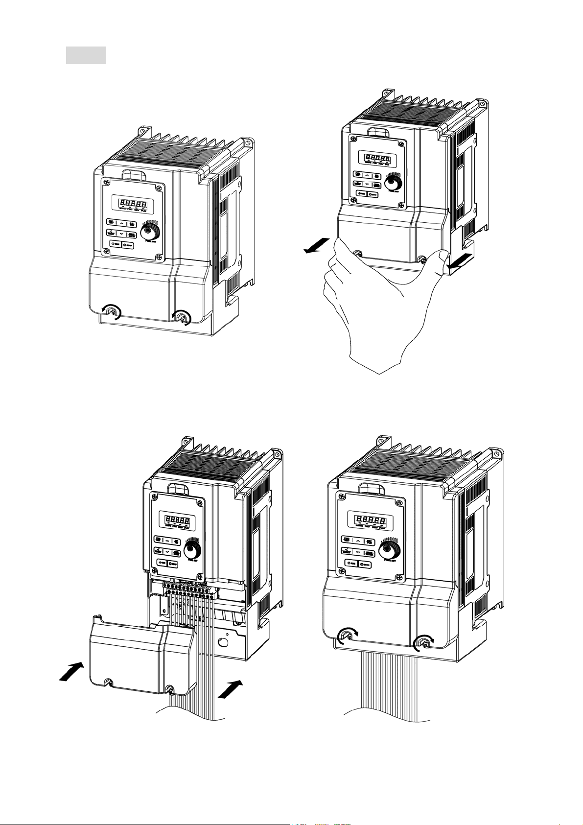
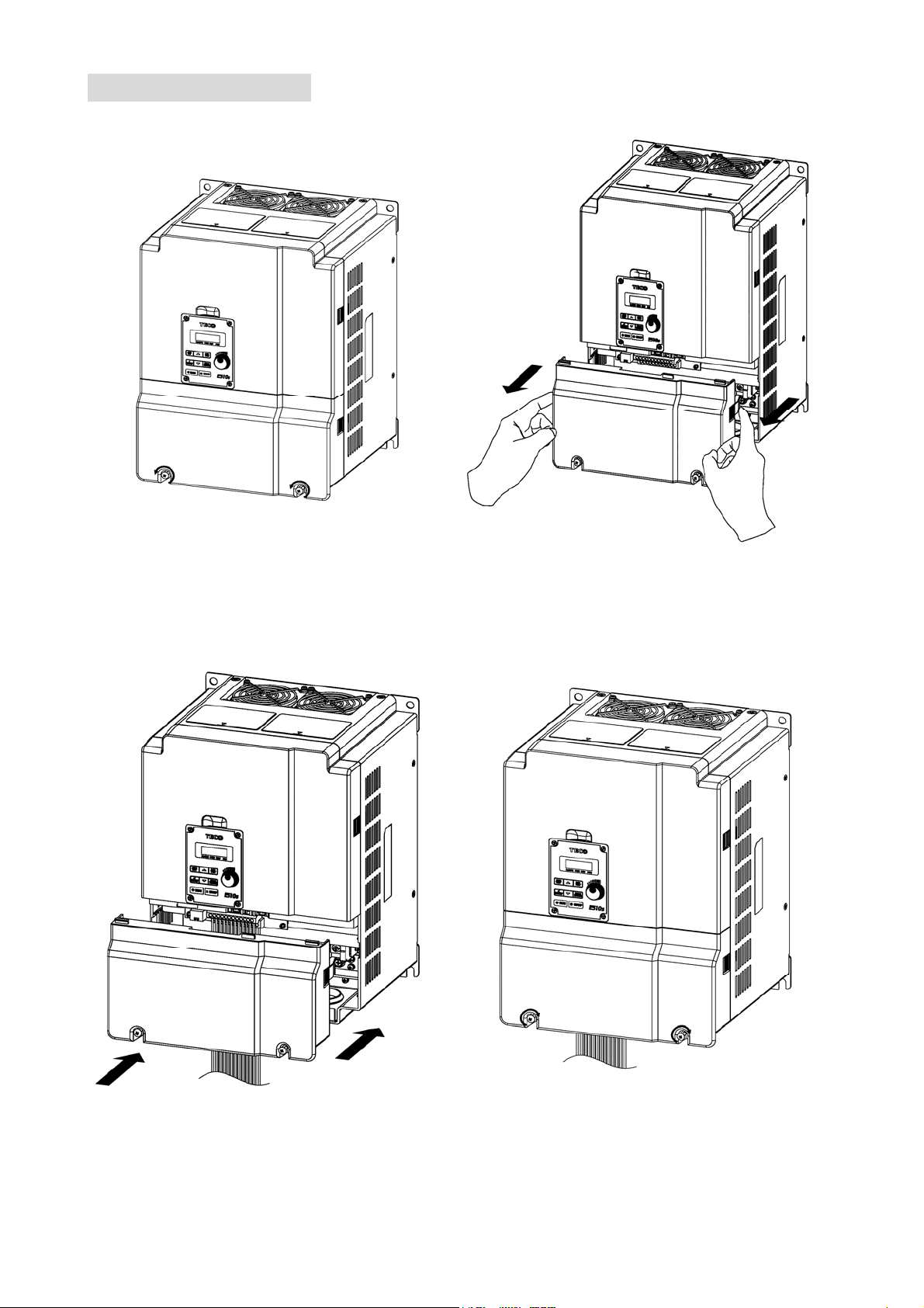
(b) 200V 2HP(single/three phase) / 200V 3HP~20HP / 400V 3HP~25HP
■ IP20
Step1:Loosen the screws
Step2:Remove the terminal cover
Step3:Wirie&Re-install the cover Step4:Tighten the screws
3-7
Page 22
■ NEMA1
Step1:Loosen the screws
Step2:Remove the terminal cover
Step3:Wirie&Re-install the cover Step4:Tighten the screws
3-8
Page 23
(c) 200V 25HP / 400V 30HP
Step1: Loosen the screws
Step2: Remove the terminal cover
Step3:Wirie&Re-install the cover Step4:Tighten the screws
3-9
Page 24

(d) 200V 30HP~40HP / 400V 40HP~75HP
Step1: Loosen the screws
Step2: Remove the terminal cover
Step3:Wirie&Re-install the cover Step4:Tighten the screws
3-10
Page 25

(e) 400V 20HP~75HP(with EMC filter)
Step1: Loosen the screws
Step2: Remove the terminal cover
Step3:Wirie&Re-install the cover Step4:Tighten the screws
3-11
Page 26

3.2.2 Installation space
Provide sufficient air circulation space for cooling as shown in examples below.
Install the Inverter on surfaces that provide good heat dissipation。
Frame1 models:2P5/201/202(three phase)/401/402
Distributor
inside
12cm
Distributor
inside
Side by side installation:
Provide te necessary physical space and cooling based on the ambient temperature and the heat
loss in the panel.
5cm
12cm
Front view Side view
(2P5/201/202/401/402)
Operator
panel
5cm
Note: means “cooling fan”.
5cm
3-12
Page 27

3.2.3 External View
3.2.3.1 IP20/NEMA 1
(a) 200V 0.5HP~1HP / 400V 1HP~2HP / 200V 2HP(3PH)
■ IP20
■ NEMA1
3-13
Page 28

(b) 200V 2HP(1/3PH) / 200V 3HP~20HP / 400V 3HP~25HP
■ IP20
■ NEMA1
3-14
Page 29

(c) 200V 25HP / 400V 30HP
(d) 200V 30HP~40HP / 400V 40HP~75HP
3-15
Page 30

■ Interior layout
(a) 200V 0.5HP~1HP / 400V 1HP~2HP / 200V 2HP(three phase)
Operator panel
RJ45 communication port
TM2 terminal
TM1 terminal
(b) 200V 2HP(single/three) / 200V 3HP~20HP / 400V 3HP~25HP
Operator panel
Ground terminal
RJ45 communication port
TM1 terminal
TM2 terminal
Ground terminal
3-16
Page 31

p
(c) 200V 25HP / 400V 30HP (d) 200V 30HP~40HP / 400V 40HP~75HP
O
RJ45 communication port
erator panel
Ground terminal
■ Warning label
(a) 200V 0.5HP~20HP / 400V 1HP~25HP
TM2
terminal
TM1
terminal
(b) 200V 25HP~40HP / 400V 30HP~75HP
3-17
Page 32

3.3 Wiring Guidelines
3.3.1. Power cables:
L1(L)、L2、L3(N) for three phase input models.
L1(L) and L3(N) for single phase input models. (L2 terminal will be removed)
Motor cable must be connected T1, T2, T3 of TM1 terminals.
Power cables should be selected by the following conditions:
Only can use copper wires, and the diameter needs to use 105 degrees Celsius level.
The minimum power cable rated voltage level of 240V system is 300V.
For the safety, power cables should be connected by “O” type terminal.
Warning
Connection of supply line cable to terminals T1,T2, T3 will result in serious damage to the
drive components. Power cables should be separated with the other high voltage and high
current cables to prevent the noise intereference, please refer the photo below:
Inverter with dedicated power line
Install a supply RFI filter or Isolation transformer when the power source is shared with
other high power electrical equipment as shown below
3-18
Page 33

3.3.2 Control cable selection and wiring
Control cables should be connected to terminal block TM2, Choose power & Control
cables according to the following criteria:
Use copper wires with correct diameter and temperature rating of 65/70°C
Minimum cable voltage rating for 200V type inverters should be 300VAC. Minimum cable
voltage rating for 400V type inverters should be 600VAC
Route all cables away from other high voltage or high current power lines to reduce
interference effects。
Use a twisted pair shielded cable and connect the shield (screen) wire to the ground
terminal at the inverter end only. Cable length should not exceed 50 meters
3-19
Page 34

(N)
3.3.3. Wiring and EMC guidelines
For effective interference suppression, do not route power and control cables in the same
conduit or trunking
To prevent radiated noise, motor cable should be put in a metal Conduit. Alternatively an
armored or shielded type motor cable should be used
Motor cable and signal lines of other control equipment should be at the least 30 cm
apart
For effective suppression of noise emissions the cable armor or shield must be grounded
at both ends to the motor and the inverter ground. These connections should be as short
as possible
L1(L)
L3
1. Protective Earth Conductor. Conductor size for
enclosure & Back plate must comply with the
local electrical standards. Min 10mm²
2. Back plate. Galvanised steel (Unpainted)
3. Ferrite core / Output reactor ferrite cores can
be used to reduce radiated noise due to long
motor cables. If ferrite core is used loop motor
wires, 3 times round the core. Install core as
close to the inverter as possible. Output
reactors provide additional benefit of reducing
dv/dt for protection of motor windings.)
4. Metal Cable clamp. no more than 150mm from
the inverter.
Note:
If no enclosure & back plate is used then connect
the cable shield by a good 360 degree termination
to the Inverter output terminal E.
5. Screened (Shielded four core cable)
6. Separate Protective Earth wire, routed outside
motor cable separated be at least 100mm.
Note:
This is the preferred method specially for large
output cables and long length.
Multi-core screened (3 core & protective earth)
can be used for small power and short length
7. Connect the cable shield by a good 360º
termination and connect to the motor
protective earth terminal. This link must be as
short as possible.
8. Motor Earth terminal(Protective Earth)
3-20
Page 35

3.3.4. Failure liability
Teco bears no responsibility for any failures or damaged caused to the inverter if the
recommendations in this instruction manual have not been followed specifically points listed
below:
If a correctly rated Fuse or Circuit breaker has not been installed between the power
source and the inverter.
If a magnetic contactor, a phase capacitor, burst absorber and LC or RC circuits have
been connected between the inverter and the motor.
If an incorrectly rated three-phase squirrel cage induction motor has been used
When one inverter is driving several motors, the total current of all motors running
simultaneously must be less than the rated current of the inverter, and each motor has to
be equipped with a correctly rated thermal overload relay.
“Only Intended For Use In A Pollution Degree 2 Environment” or equivalent.
Since there is no over speed protection there will be no liablity due to overspeed
damage.
3-21
Page 36

3.3.5 Considerations for peripheral equipment
Ground
Ground
Ensure that the supply voltage is correct. A molded-case
Power
Circuit
Breaker
& RCD
Magnetic
contactor
AC reactor
for power
quality
improvement
Input noise
filter
Inverter
Motor
circuit breaker or fused disconnect must be installed
between the AC source and the inverter
Use a molded-case circuit breaker that conforms to the
rated voltage and current of the inverter.
Do not use the circuit breaker as the run/stop switch for
the inverter.
Residual Current Circuit Breaker(RCD)
Current setting should be 200mA or above and the
operating time at 0.1 second or longer to prevent
malfunctions.
Normally a magnetic contactor is not needed.
A contactor can be used to perform functions such as
external control and auto restart after power failure.
Do not use the magnetic contactor as the run/stop switch
of the inverter.
When a 200V/400V inverter with rating below 15KW is
connected to a high capacity power source (600KVA or
above) then an AC reactor can be connected for power
factor improvement and reducing harmonics.
E510s has a built-in filter (Class A/First Environment
Category C2, except for Frame 4)
To satisfy the required EMC regulations for your specific
application you may require an additional EMC filter.
Connect the single phase power to Terminals, L1(L) &
L3(N).
Warning! Connecting the input terminals T1, T2, and T3 to
AC input power will damage the inverter.
Output terminals T1, T2, and T3 are connected to U, V, and
W terminals of the motor.
To reverse the motor rotation direction just swap any two
wires at terminals T1, T2, and T3.
Ground the Inverter and motor correctly.
Ground Resistance for 200V have to less than 100 Ohms.
Ground Resistance for 400V have to less than 10 Ohms
Three-phase induction motor.
Voltage drop on motor due to long cable can be
calculated, volts drop should be less than 10%.
The formula of Phase-to-phase voltage drop is
(V) =
line(m)×current×10
3 ×resistance of wire (Ω/km)×length of
-3
3-22
Page 37

3.3.6 Ground connection
Inverter ground terminal must be connected to installation ground correctly and
according to the required local wiring regulations
Ground cable size must be according to the required local wiring regulations. Ground
connection should be as short as possible
Do not share the ground of the inverter with other high current loads (Welding machine,
high power motors). Ground each unit separately
Ensure that all ground terminals and connections are secure
Do not make ground loops when several inverters share a common ground point.
Please leave at least 5cm while installing inverter side by side in order to provide enough
cooling space.
(a) Corrent (b) Correct (c) Incorrect
Input power cable length
The length of the cables between the power source and/or the motor and inverter can
casue a significant phase to phase voltage reduction due to the voltage drop across the
cables. The maximum voltage drop is 2%, if this value is exceeded, a wire size having large
diameter is needed. To calculate phase to phase voltage drop by the following formula.
Phase-to-phase voltage drop(V)=
3 ×resistance of wire(Ω/km)×length of line(m)×current (A) ×10
Installing an AC line reactor
If the inverter is connected to a large-capacity power source (600kVA or more), install an
optional AC reactor on the input side of the inverte, it can improve the power factor on
the power supply side.
Cable length & Carrier frequency
The followable setting of the PWM carrier frequency is also determined by motor cable
length and is specified in the following table.
Cable length of motor
Recommanded carrier
in m (ft.)
frequenc allowed
parameter 11-01
<30m
(100)
16kHz(max) 10kHz(max) 5kHz(max) 2kHz(max)
30m ~ 50m
(100~165)
50m ~100m
-3
(166~328)
≧100m
(329)
※ The minimum carrier frequency of SLV control mode is 4K, please confirm the cable length.
3-23
Page 38

3.3.7 Single / Multi Pump Dedicated Wiring Diagram
PUMP Wiring Diagram for Pressure Sensor of Voltage Type
Single Pump:
Multi-Pump:
00-02 = 1 (Control Circuit Terminal); 04-00 = 0 (0~10V)
10-00 = 0 (Target Source: KeyPad); 10-01 = 2 (Feedback Source: AI2)
10-03 = XXX1b (PID is enbaled); 23-00 = 1 (PUMP); 23-01 = 1 (Master)
S(+) S(-) SF1 SG SF2 COM S2 S4 S6
00-02 = 1 (Control Circuit Terminal); 04-00 = 0 (0~10V)
10-00 = 0 (Target Source: KeyPad); 10-01 = 2 (Feedback Source: AI2)
10-03 = XXX1b (PID is enbaled); 23-00 = 1 (PUMP); 23-01 = 3 (Follower
2)
S(+) S(-) SF1 SG SF2 COM S2 S4 S6
S1 S3 S5 24V AI1R2A R2B R1A R1B R1C
S1 S3 S5 24V AI1R2A R2B R1A R1B R1C
AI2
10V AOAGND
AI2
10V AOAGND
00-02 = 1 (Control Circuit Terminal); 04-00 = 0 (0~10V)
10-00 = 0 (Target Source: KeyPad); 10-01 = 2 (Feedback Source: AI2)
10-03 = XXX1b (PID is enbaled); 23-00 = 1 (PUMP); 23-01 = 2 (Follower
1)
S(+) S(-) SF1 SG SF2 COM S2 S4 S6
00-02 = 1 (Control Circuit Terminal); 04-00 = 0 (0~10V)
10-00 = 0 (Target Source: KeyPad); 10-01 = 2 (Feedback Source: AI2)
10-03 = XXX1b (PID is enbaled); 23-00 = 1 (PUMP); 23-01 = 4 (Follower
3)
S(+) S(-) SF1 SG SF2 COM S2 S4 S6
S1 S3 S5 24V AI1R2A R2B R1A R1B R1C
S1 S3 S5 24V AI1R2A R2B R1A R1B R1C
AI2
10V AOAGND
AI2
10V AOAGND
JP1
NPN
PNP
SW2
I
JP3
V
+
-
3-24
Page 39

PUMP Wiring Diagram for PressureSensor of Current Type
Single Pump:
Multi-Pump:
00-02 = 1 (Control Circuit Terminal); 04-00 = 1 (4~20mA)
10-00 = 0 (Target Source: KeyPad); 10-01 = 2 (Feedback Source: AI2)
10-03 = XXX1b (PID is enabled), 23-00 = 1 (PUMP); 23-01 = 1 (Master)
S(+) S(-) SF1 SG SF2 COM S2 S4 S6
S1 S3 S5 24V AI1R2A R2B R1A R1B R1C
10V AOAGND
00-02 = 1 (Control Circuit Terminal); 04-00 = 1 (4~20mA)
10-00 = 0 (Target Source: KeyPad); 10-01 = 2 (Feedback Source: AI2)
10-03 = XXX1b (PID is enabled), 23-00 = 1 (PUMP); 23-01 = 2 (Follower 1)
AI2
S(+) S(-) SF1 SG SF2 COM S2 S4 S6
S1 S3 S5 24V AI1R2A R2B R1A R1B R1C
E510s Multi-Pump Operation: Follower 2 E510s Multi-Pump Operation: Follower 3
00-02 = 1 (Control Circuit Terminal); 04-00 = 1 (4~20mA)
10-00 = 0 (Target Source: KeyPad); 10-01 =2 (Feedback Source: AI2)
10-03 = XXX1b (PID is enabled), 23-00 = 1 (PUMP); 23-01= 3
(Follower 2)
S(+) S(-) SF1 SG SF2 COM S2 S4 S6
TM2
S1 S3 S5 24V AI1R2A R2B R1A R1B R1C
10V AOAGND
00-02 = 1 (Control Circuit Terminal); 04-00 = 1 (4~20mA)
10-00 = 0 (Target Source: KeyPad); 10-01 =2 (Feedback Source: AI2)
10-03 = XXX1b (PID is enabled), 23-00 = 1 (PUMP); 23-01 = 4
(Follower 3)
AI2
S(+) S(-) SF1 SG SF2 COM S2 S4 S6
TM2
S1 S3 S5 24V AI1R2A R2B R1A R1B R1C
Master
NPN
JP1
AI2
10V AOAGND
AI2
10V AOAGND
PNP
Operation
Switch
I
JP3
V
Follower
NPN
JP1
PNP
V
I
JP3
Notes1: The position of dip switch requires being correct (JP1,JP3), it is required to reconnect
the power after setting Master/Slave.
Notes2: When the communication modes is selected to be multiple pumps in parallel
connection (09-01=3), the baud rate settings 09-02 of Master and Slave are required
to be consistent.
3-25
Page 40

Notes3: Refer to parameter 23-31 for the actions in parallel connection modes.
Notes4: In the wiring of multi-pump current type pressure sensor, it is required to adjust
Slave to be 04-07=252.0% and 04-08=-25.0%
Notes5: In multi-pump operation, if one of the inverter does not Power ON, the 24V of
connection is also need to disconnect to avoid magnetoresistance effect.
3-26
Page 41

3.4 Specifications
3.4.1 Product specifications
200V Class:Single phase
Mod e l: E510-□□□-SH1F 2P5 201 202 203
Horse power (HP) 0.5 1 2 3
Suitable motor capacity (KW) 0.4 0.75 1.5 2.2
Rated output current (A) 3.1 4.5 7.5 10.5
Rated capacity (KVA) 1.2 1.7 2.90 4.00
Input voltage range(V) Single phase:200~240V, 50/60Hz
Allowable voltage fluctuation -15%~+10%
Output voltage range(V) Three phase:0~24 0V
Input current (A)* 8.5 12 16 23.9
Inverter net weight (KG) 1.65 1.65 2.5 2.5
Inverter net weight(with Filter) (KG) 1.9 1.9 2.8 2.8
Allowable momentary power loss time(s) 2.0 2.0 2.0 2.0
Enclosure IP20/NEMA1
200V Class:Single/Three phase
Mod e l: E510-□□□-SH 2P5 201 202 203
Horse power (HP) 0.5 1 2 3
Suitable motor capacity (KW) 0.4 0.75 1.5 2.2
Rated output current (A) 3.1 4.5 7.5 10.5
Rated capacity (KVA) 1.2 1.7 2.90 4.00
Input voltage range(V) Single/Three:200~240V, 50/60Hz
Allowable voltage fluctuation -15% ~ +10%
Output voltage range(V) Three phase:0~ 240V
Input current (A)* 8.5/4.5 12/6.5 16/11 23.9/12.5
Inverter net weight (KG) 1.6 1.6 2.5 2.5
Allowable momentary power loss time(s) 2.0 2.0 2.0 2.0
Enclosure IP20/NEMA1
200V Class:Three phase
Mod e l: E510-□□□-SH3 202 205 208 210 215 220
Horse power (HP) 2 5 7.5 10 15 20
Suitable motor capacity (KW) 1.5 4 5.5 7.5 11 15
Rated output current (A) 7.5 17.5 26 35 48 64
Rated capacity (KVA) 2.9 6.7 9.9 13.3 20.6 27.4
Input voltage range(V) Three phase:200~240V,50/60Hz
Allowable voltage fluctuation -15%~+10%
Output voltage range(V) Three phase:0~ 2 40 V
Input current (A)* 11 20.5 33 42 57 70
Inverter net weight (KG) 1.6 2.5 6.5 6.5 10.1 10.4
Allowable momentary power loss time(s) 2.0 2.0 2.0 2.0 2.0 2.0
Enclosure IP20/NEMA1
3-27
Page 42

Model:E510-□□□-SH3 225 230 240
Horse power (HP) 25 30 40
HD/ND Suitable motor capacity (kW) 18.5/22 22/30 30/37
HD/ND Rated output current (A) 73/80 85/110 115/138
HD/ND Rated capacity (KVA) 27.8/30.1 32.4/41.9 43.8/52.6
Input voltage range(V) Three phase:200~240V,50/60Hz
Allowable voltage fluctuation -15%~+10%
Output voltage range(V) Three phase:0~ 2 40 V
Input current (A)* 79.4/85.9 92.4/119.6 125/150
Inverter net weight (KG) 10 30 30
Allowable momentary power loss time(s) 2.0 2.0 2.0
Enclosure IP20/NEMA1
400V Class:Three phase
Mod e l: E510-□□□-SH3(F) 401 402 403 405
Horse power (HP) 1 2 3 5
Suitable motor capacity (KW) 0.75 1.5 2.2 4.0
Rated output current (A) 2.5 3.8 5.3 9.2
Rated capacity (KVA) 1.7 2.9 4.0 6.7
Input voltage range(V) Three phase:380~480V,50/60Hz
Allowable voltage fluctuation -15%~+10%
Output voltage range(V) Three phase:0~ 480V
Input current (A)* 4.2 5.6 7.3 11.6
Inverter net weight (KG) 1.7 1.7 2.5 2.5
Inverter net weight(with Filter) (KG) 1.9 1.9 2.8 2.8
Allowable momentary power loss time(s) 2.0 2.0 2.0 2.0
Enclosure IP20/NEMA1
Mod e l: E510-□□□-SH3(F) 408 410 415 420 425
Horse power (HP) 7.5 10 15 20 25
Suitable motor capacity (KW) 5.5 7.5 11 15 18.5
Rated output current (A) 13.0 17.5 24 32 40
Rated capacity (KVA) 9.9 13.3 19.1 24 30.5
Input voltage range(V) Three phase:380~480V,50/60Hz
Allowable voltage fluctuation -15%~+10%
Output voltage range(V) Three phase:0~ 4 80V
Input current (A)* 17 23 31 38 48
Inverter net weight (KG) 6.7 6.7 6.7 13.7 13.7
Allowable momentary power loss time(s) 2.0 2.0 2.0 2.0 2.0
Enclosure IP20/NEMA1
3-28
Page 43

Mod e l: E510-□□□- SH3(F) 430 440
Horse power (HP) 30 40
HD/ND Suitable motor capacity (kW) 22/30 30/37
HD/ND Rated output current (A) 45/58 60/73
HD/ND Rated capacity (KVA) 34.3/44.2 45.7/55.6
Input voltage range(V) Three phase : 380~480V,50/60Hz
Allowable voltage fluctuation +10% - 15%
Output voltage range(V) Three phase : 0~ 4 80V
Input current (A)* 48.9/63 65.2/78.3
Inverter net weight (KG) 10 24
Inverter net weight(with Filter) (KG) 22.8 47.2
Allowable momentary power loss time(s) 2.0
Enclosure IP20/NEMA1
Mod e l: E510-□□□- SH3(F) 450 460 475
Horse power (HP) 50 60 75
HD/ND Suitable motor capacity (kW) 37/45 45/55 55/75
HD/ND Rated output current (A) 75/88 91/103 118/145
HD/ND Rated capacity (KVA) 57.2/67.1 69.3/78.5 89.9/111
Input voltage range(V) Three phase : 380~480V,50/60Hz
Allowable voltage fluctuation +10% - 15%
Output voltage range(V) Three phase : 0~ 4 80V
Input current (A)* 81.5/95.7 98.9/112 130/159
Inverter net weight (KG) 24 24 24
Inverter net weight(with Filter) (KG) 47.2 47.2 52.2
Allowable momentary power loss time(s) 2.0 2.0 2.0
Enclosure IP20/NEMA1
Notes:
1. Take standard 4-poles induction motor as the base.
2. E510s model is designed to use inheavy duty conritions, the factory setting is HD (Heavy Duty
type) mode.
3. The overload capacity of E510s model HD (Heavy Duty) is 150%/1min, 200%/2sac. See the table
below for the carrier frequency default setting and range.
4. The overload capacity of E510s model ND (Normal Duty) is 120%/1min, carrier frequency range is
1kHz~16kHz, the default setting is 2kHz.
5. If the carrier frequency is greater than default, it need to adjust the load current based on the
de-rating curve.
Inverter voltage and capacity HD mode carrier frequency range
ND mode carrier
200V Class 400V Class V/F SLV PMSLV
1~20HP 1~25HP 1~16kHz 4~16kHz 4~8kHz 5kHz
30HP 1~16kHz 4~16kHz(6) 4~8kHz 5kHz
25~40HP 40~50HP 1~12kHz 4~12kHz(6) 4~8kHz 5kHz
60~75HP 1~10kHz 4~10kHz 4~8kHz 5kHz
3-29
frequency range
Page 44

6. If control mode (00-00) is set to 2 (SLV mode) and maximum frequency (01-02) is larger than
80Hz, the carrier frequency range is 2~8kHz.
The following table shows maximum output frequency for each control mode.
Duty Cycle Control Mode Other Setings Max. Output Frequency
V/F Maximum output frequency is 599Hz 599Hz
200V 1~10HP, 400V 1~15HP 150Hz
200V 15~20HP, 400V 20HP 110Hz
400V 25HP 100Hz
Heavy Duty
(00-27=0)
Normal
Duty
(00-27=1)
Model
No.
11-301-21-xxx-30 series
11-301-21-2P5-30 200-240 / 1Ф 8.5 240/3Ф 3.1 0.4
11-301-21-201-30 200-240 / 1Ф 12 240/3Ф 4.5 0.75
11-301-21-202-30 200-240 / 1Ф 16 240/3Ф 7.5 1.5
11-301-21-203-30 200-240 / 1Ф 23.9 240/3Ф 10.5 2.2
11-301-43-xxx-30 series
11-301-43-401-30 380-480 / 3Ф 4.2 480/3Ф 2.3 0.75
11-301-43-402-30 380-480 / 3Ф 5.6 480/3Ф 3.8 1.5
11-301-43-403-30 380-480 / 3Ф 7.3 480/3Ф 5.2 2.2
11-301-43-405-30 380-480 / 3Ф 11.6 480/3Ф 9.2 4.0
11-301-43-408-30 380-480 / 3Ф 17.0 480/3Ф 13.0 5.5
11-301-43-410-30 380-480 / 3Ф 23.0 480/3Ф 17.5 7.5
11-301-43-415-30 380-480 / 3Ф 31.0 480/3Ф 24 11
11-301-43-420-30 380-480 / 3Ф 38.0 480/3Ф 32 15
11-301-43-425-30 380-480 / 3Ф 48.0 480/3Ф 40 18.5
11-301-43-430-30 380-480 / 3Ф 48.9/63.0 480/3Ф 45/58 22/30
11-301-43-440-30 380-480 / 3Ф 65.2/78.3 480/3Ф 60/73 30/37
11-301-43-450-30 380-480 / 3Ф 81.5/95.7 480/3Ф 75/88 37/45
11-301-43-460-30 380-480 / 3Ф 98.9/112 480/3Ф 91/103 45/55
11-301-43-475-30 380-480 / 3Ф 130/159 480/3Ф 118/145 55/75
SLV
PMSLV
V/F
SLV /PMSLV Without standard loading mode -
Input Voltage
200V 25~40HP, 400V 30~75HP,
carrier (11-01) is set as 8K or below 8K
200V 25~40HP, 400V 30~75HP,
carrier (11-01) is above 8K
Please refer parameter group 22 of
chapter 4.3 (PM motor parameter group)
200V 25~40HP, 400V 30~75HP
The maximum frequency is 120Hz
(V)
Input
Current
(A)
Max. Output
Voltage (V)
100Hz
80Hz
599Hz
120Hz
Rated Output
Current (A)
Output
Power
(KW)
For 11-301-43-430/40/50/60/75-30, these models have two operation modes for setting.
N.D:Normal Duty operation mode.
H.D:Heavy Duty operation mode.
3-30
Page 45

3.4.2 General specifications
Item
Control mode V/F, SLV, PMSLV control mode
Output Frequency 0.01~599.00Hz
Starting Torque 150% / 1Hz (SLV mode),150% / 3Hz(V/F mode)
Frequency resolution
Frequency
Frequency setting
Frequency limit Lower and upper frequency limits 3 skip frequency settings.
Run Operation set
V / F curve setting 15 fixed curves and 1 customized curve
Carrier frequency 1~16kHz (factory setting is 5kHz)
Acceleration and
deceleration control
Main
Control
Features
Multifunction input Refer to description on Group 3
Multifunction output Refer to description on Group 3
Multifunction analog output Refer to description on Group 4
Digital input:0.01Hz
Analog input:0.06Hz/60Hz
Keypad:set directly with ▲▼keys or the VR on the keypad
External input terminals: AI1、AI2 (0/2-10V, 0/4-20mA)
Multifunction input UP/DOWN function(Group 3)
Set frequency by communication method
Keypad RUN/STOP buttom
External terminals:
Multi-operation mode 2/3 wires selection
JOG operation
Run signal by communication method
2 off acceleration/deceleration time parameters
4 off S curves parameters
E510s
Display
Protective
Functions
Overload detection, 16 preset speed, Auto-run, Acc/Dec
Main features
LED display
LED status indicator Run, Stop, Forward, Reverse and etc.
Overload protection (OL1) Electrical overload protection curve
Overload protection (OL2)
Over voltage
Under Voltage
Momentary Power Loss
Restart
Stall Prevention
Short-circuit output terminal
Grounding Fault
Other protection features
switch(2 stages), Main/Alt run command select, Main/Alt
frequency command select, PID control, Torque boost, V/F
start frequency, Fault reset, Fire mode, Multi-Pump function.
Parameter, Paramete value, Frequency, Line speed, DC
voltage, Output voltage, Output current, PID feedback, Input
and output terminal status, Heat sink temperature, Firmware
version, Fault list.
H.D mode:150% for 60s (200% for 2s)
N.D mode:120% for 60s
200V Class:DC bus voltage higher than 410Vdc
400V Class:DC bus voltage higher than 820Vdc
200V Class:DC bus voltage lower than 190V
400V Class:DC bus voltage lower than 380V
Inverter auto-restart after a momentary power loss
Stall prevention for acceleration/deceleration operation
Electronic circuit protection
Electronic circuit protection
Protection for overheating of heat sink, Fault output, Reverse
prohibit, Prohibit for direct start after power up and error
recovery, Parameter lock up, STO (Safety Torque Off).
3-31
Page 46

Built-in RS485 communication for one to one or one to many.
Communication control
Operating temperature
Storage temperature -20~60℃
Humidity
Environment
Vibration
Enclosure IP20/NEMA1
Built-in BACnet communication for building control.
(Ex:Fire protection system, Air conditioning system,
Monitoring system and Access control system)
IP20/NEMA1 type:
-10~50°C(without sticker or upper dust cover)
-10~40°C(with sticker or upper dust cover)
95% RH or less (no condensation)
(Follow IEC60068-2-78 standard)
Frequency : 10Hz to 150Hz and return to 10Hz
Amplitude : 0.3mm (10Hz to 50Hz)
Acceleration : 2G (50Hz to 150Hz)
(According to IEC60068-2-6 standard)
3.4.3 De-rating curve
The curves are showing the applicable output current de-rate due to setting of carrier frequency and the
ambient operating temperatures of 40 and 50 degrees.
When the carrier frequency under than 10KHz, ambient temperature will not effect rated current.
When the carrier frequency higher than 10KHz:
If the ambient temperature is under 40℃, inverter can output 100% rated current on 16KHz.
If the ambient temperature is under 50℃, inverter only can output 85% rated current on 16KHz.
It is required to derate 1.5% of output current at each additional degrees once the ambient
inverter is higher than 50 degrees.
Note:
--------------- De-rating curve of 40℃ ambient temperature
……………………. De-rating curve of 50℃ ambient temperature
Frame 1/2/3/4 (Single phase/Three phase 200V 2HP, Three phase200V 0.5~2HP/5HP~20HP)
3-32
Page 47

Frame2 (Three phase 200V 3HP)
Frane 5/6 (Three 200V 25HP)
Frame 5/6 (Three phase 200V 30HP、40HP)
3-33
Page 48

Frame 1/2/3 (Three phase 400V 1HP~5HP, 10HP, 20HP~25HP)
Frame 3 (Three phase 400V 8HP)
Frame 3 (Three phase 400V 15HP)
3-34
Page 49

Frame 5 (Three phase 400V 30HP)
Frame 6 (Three phase 400V 40HP~50HP)
Frame 6 (Three phase 400V 60HP~75HP)
3-35
Page 50

3.4.4 Capacitor Reforming Guide After Long Storage
For correct performance of this product after long storage before use it is important that Inverter
Capacitors are reformed according to the guide below:
Storage
time
≦1year Apply rated voltage of inverter in the normal way
Between
1-2 years
≧2 years
Note1:Please refer the rated voltage according to model label of inverter
Apply rated voltage of inverter(Note1) to the product for one hour before using the
inverter
Use a variable AC power supply to
1. Connecting 25% rated voltage of inverter for 30 minutes.
2. Connecting 50% rated voltage of inverter for 30 minutes.
3. Connecting 75% rated voltage of inverter for 30 minutes.
4. Connecting 100% rated voltage of inverter for 210 minutes.
Once the procedures completed, inverter just can be used normally
Procedure to re-apply voltage
3-36
Page 51

3.5 Standard Wiring
10V
AI1
P
P
AI2
AGND
E
3-37
Page 52

3.6 Terminal description
3.6.1 Description of main circuit terminal
Terminal symbol TM1 function description
L1(L)
L2 Single/Three phase: L1(L)/L2/L3(N)
L3(N) Three phase: L1/L2/L3
T1
T2
T3
P
BR
Main power input,
Inverter output, connect to U/V/W terminals of motor
Externally connected braking resistor
(Please see the braking resistors reference on chapter 6)
Ground terminal
Single phase: L1(L)/L3(N)
Main power terminal of Single phase 200V Class 0.5~1HP
Notes:The screw on L2 terminal will be removed for single phase input supply models.
Main power terminal of Single/Three phase 200V Class 0.5~1HP and Three phase 400V Class
1~2HP.
3-38
Page 53

Main power terminal of Single/Three phase 200V Class 2~3HP
L1(L)
Main power terminal of Single/Three phase 200V Class 2~3HP, Three phase 200V Class 5HP and
Three phase 400V Class 3~5HP
Main power terminal of Three phase 200V Class 7.5~20HP and Three phase 400V Class 7.5~20HP
L2 L3(N)
BR T1 T2
P
T3
Main power terminal of Three phase 200V Class 25HP and Three phase 400V Class 30HP
Main power terminal of Three phase 200V Class 30~40HP and Three phase 400V Class 40~75HP
3-39
Page 54

3.6.2 Description of control circuit terminal
Type Terminal Function Signal level
Digital
Input
Relay
Output
24Vdc
Supply
Analog
Input
Analog
Output
STO
Terminal
RS485
Modbus
S1
S2
S3
S4
S5
S6
R1A Normal Open
R1B Normal Close
R1C Common Point
R2A
R2B
24V Common point of PNP input (JP1 switch to PNP)
COM Common point of NPN input (JP1 switch to NPN)
10V Built-in power for external potentiometer 10V (max current is 20mA)
AI1/AV1
AI2/AV2
AGND Analog input common point. ----
Ground terminal. ----
AO Analog output terminal. 0-10V,(max current is 2mA)
AGND Analog input common point. ----
SF1,SF2
SG 24V for SF1/SF2
S(+)
S(-)
Please refer to group3 (digital input functions) for
default setting and setting range.
Please refer to group3 (digital
output functions) for default
Normal Open
setting and setting range.
Multi-analog input 1 (0-10V/0-20mA)
(Please use JP2 to select voltage or current input)
Multi-analog input 2 (0-10V/0-20mA)
(Please use JP3 to select voltage or current input)
Safety switch, the output voltage of inverter will
be cut off when the terminal switches on.
RS485/MODBUS (Baud rate setting 9600~38400) Differential input and output
24 VDC, 8 mA photocoupler
isolation. (The max. input
voltage is 30 Vdc, input
resistance is 4.3kΩ)
High Logic: 13V
Low Logic: 10V
250VAC/1A
(30VDC/1A)
±15%
(max output current is 60mA)
Resistance for voltage input
is 153KΩ; for current input
is :500Ω
Control terminal:
3-40
Page 55

Jumper function description
Jumper Symbol Function Signal reference Note
NPN input
JP1
JP2 /JP3
NPN/PNP
selectable
External signal type
selection
PNP input
0-20mA / 4-20mA
Analog signal
0/2-10V
Analog signal
Factory default setting
Set parameter
00-05/00-06 to 2 or 3
(External analog input) to
become effective
3-41
Page 56

3.7 Outline dimensions
IP20 dimensions
200V Class single phase:0.5HP~1HP
200V Class three phase:2HP
400V Class three phase:1HP~2HP
Inverter Model
E510-2P5-SH
E510-201-SH
E510-2P5-SH1F
E510-201-SH1F
E510-202-SH3
E510-401-SH3
E510-402-SH3
E510-401-SH3F
E510-402-SH3F
Dimensions in mm (inch)
W W1 W2 H H1 D E t Q
90.6
(3.57)
90.6
(3.57)
90.6
(3.57)
90.6
(3.57)
90.6
(3.57)
90.6
(3.57)
90.6
(3.57)
90.6
(3.57)
90.6
(3.57)
80.5
(3.17)
80.5
(3.17)
80.5
(3.17)
80.5
(3.17)
80.5
(3.17)
80.5
(3.17)
80.5
(3.17)
80.5
(3.17)
80.5
(3.17)
80.5
(3.17)
80.5
(3.17)
80.5
(3.17)
80.5
(3.17)
80.5
(3.17)
80.5
(3.17)
80.5
(3.17)
80.5
(3.17)
80.5
(3.17)
164
(6.46)
164
(6.46)
164
(6.46)
164
(6.46)
164
(6.46)
164
(6.46)
164
(6.46)
164
(6.46)
164
(6.46)
153
(6.02)
153
(6.02)
153
(6.02)
153
(6.02)
153
(6.02)
153
(6.02)
153
(6.02)
153
(6.02)
153
(6.02)
151.4
(5.96)
151.4
(5.96)
151.4
(5.96)
151.4
(5.96)
151.4
(5.96)
151.4
(5.96)
151.4
(5.96)
151.4
(5.96)
151.4
(5.96)
47
(1.85)
47
(1.85)
47
(1.85)
47
(1.85)
47
(1.85)
47
(1.85)
47
(1.85)
47
(1.85)
47
(1.85)
5
(0.19)
5
(0.19)
5
(0.19)
5
(0.19)
5
(0.19)
5
(0.19)
5
(0.19)
5
(0.19)
5
(0.19)
Net Weight
in kg/(lbs)
M4 1.6/(3.5)
M4 1.6/(3.5)
M4 1.7/(3.8)
M4 1.7/(3.8)
M4 1.7/(3.8)
M4 1.7/(3.8)
M4 1.7/(3.8)
M4 1.7/(3.8)
M4 1.7/(3.8)
3-42
Page 57

200V Class single/three phase:2HP
400V Class three phase:3~25HP
200V Class three phase:3~20HP
Inverter Model
E510-202-SH
E510-203-SH
E510-202-SH1F
E510-203-SH1F
E510-205-SH3
E510-403-SH3
E510-405-SH3
E510-403-SH3F
E510-405-SH3F
E510-208-SH3
E510-210-SH3
E510-408-SH3
E510-410-SH3
Dimensions in mm (inch)
W W1 W2 H H1 H2 D D1 E t Q
128.7
(5.07)
128.7
(5.07)
128.7
(5.07)
128.7
(5.07)
128.7
(5.07)
128.7
(5.07)
128.7
(5.07)
128.7
(5.07)
128.7
(5.07)
186.9
(7.36)
186.9
(7.36)
186.9
(7.36)
186.9
(7.36)
118
(4.65)
118
(4.65)
118
(4.65)
118
(4.65)
118
(4.65)
118
(4.65)
118
(4.65)
118
(4.65)
118
(4.65)
175
(6.89)
175
(6.89)
175
(6.89)
175
(6.89)
118
(4.65)
118
(4.65)
118
(4.65)
118
(4.65)
118
(4.65)
118
(4.65)
118
(4.65)
118
(4.65)
118
(4.65)
176
(6.93)
176
(6.93)
176
(6.93)
176
(6.93)
187.6
(7.39)
187.6
(7.39)
187.6
(7.39)
187.6
(7.39)
187.6
(7.39)
187.6
(7.39)
187.6
(7.39)
187.6
(7.39)
187.6
(7.39)
260.9
(10.27)
260.9
(10.27)
260.9
(10.27)
260.9
(10.27)
177.6
(6.99)
177.6
(6.99)
177.6
(6.99)
177.6
(6.99)
177.6
(6.99)
177.6
(6.99)
177.6
(6.99)
177.6
(6.99)
177.6
(6.99)
249.8
(9.83)
249.8
(9.83)
249.8
(9.83)
249.8
(9.83)
197.5
(7.78)
197.5
(7.78)
197.5
(7.78)
197.5
(7.78)
197.5
(7.78)
197.5
(7.78)
197.5
(7.78)
197.5
(7.78)
197.5
(7.78)
273
(10.75)
273
(10.75)
273
(10.75)
273
(10.75)
152.4
(6)
152.4
(6)
152.4
(6)
152.4
(6)
152.4
(6)
152.4
(6)
152.4
(6)
152.4
(6)
152.4
(6)
202.6
(7.98)
202.6
(7.98)
202.6
(7.98)
202.6
(7.98)
147.4
(5.8)
147.4
(5.8)
147.4
(5.8)
147.4
(5.8)
147.4
(5.8)
147.4
(5.8)
147.4
(5.8)
147.4
(5.8)
147.4
(5.8)
197.6
(7.78)
197.6
(7.78)
197.6
(7.78)
197.6
(7.78)
48.2
(1.9) 5 (0.19)
48.2
(1.9) 5 (0.19)
48.2
(1.9) 5 (0.19)
48.2
(1.9) 5 (0.19)
48.2
(1.9) 5 (0.19)
48.2
(1.9) 5 (0.19)
48.2
(1.9) 5 (0.19)
48.2
(1.9) 5 (0.19)
48.2
(1.9) 5 (0.19)
76.7
(3.02)
76.7
(3.02)
76.7
(3.02)
76.7
(3.02)
6.5
(0.26)
6.5
(0.26)
6.5
(0.26)
6.5
(0.26)
Net Weight
in
Kg/(lbs)
M4 2.5/(5.5)
M4 2.5/(5.5)
M4 2.5/(5.5)
M4 2.5/(5.5)
M4 2.5/(5.5)
M4 2.5/(5.5)
M4 2.5/(5.5)
M4 2.5/(5.5)
M4 2.5/(5.5)
M4 6.5/(14.3)
M4 6.5/(14.3)
M4 6.5/(14.3)
M4 6.5/(14.3)
3-43
Page 58

Inverter Model
E510-415-SH3
E510-408-SH3F
E510-410-SH3F
E510-415-SH3F
E510-215-SH3
E510-220-SH3
E510-420-SH3
E510-425-SH3
Dimensions in mm (inch) Net Weight
W W1 W2 H H1 H2 D D1 E t Q
186.9
(7.36)
186.9
(7.36)
186.9
(7.36)
186.9
(7.36)
224.6
(8.84)
224.6
(8.84)
224.6
(8.84)
224.6
(8.84)
175
(6.89)
175
(6.89)
175
(6.89)
175
(6.89)
207
(8.15)
207
(8.15)
207
(8.15)
207
(8.15)
176
(6.93)
176
(6.93)
176
(6.93)
176
(6.93)
207
(8.15)
207
(8.15)
207
(8.15)
207
(8.15)
260.9
(10.27)
260.9
(10.27)
260.9
(10.27)
260.9
(10.27)
321.6
(12.66)
321.6
(12.66)
321.6
(12.66)
321.6
(12.66)
249.8
(9.83)
249.8
(9.83)
249.8
(9.83)
249.8
(9.83)
303.5
(11.95)
303.5
(11.95)
303.5
(11.95)
303.5
(11.95)
273
(10.75)
273
(10.75)
273
(10.75)
273
(10.75)
330.9
(13.03)
330.9
(13.03)
330.9
(13.03)
330.9
(13.03)
202.6
(7.98)
202.6
(7.98)
202.6
(7.98)
202.6
(7.98)
206.1
(8.11)
206.1
(8.11)
206.1
(8.11)
206.1
(8.11)
197.6
(7.78)
197.6
(7.78)
197.6
(7.78)
197.6
(7.78)
201.1
(7.92)
201.1
(7.92)
201.1
(7.92)
201.1
(7.92)
76.7
(3.02)
76.7
(3.02)
76.7
(3.02)
76.7
(3.02)
94
(3.7) 8 (0.31)
94
(3.7) 8 (0.31)
94
(3.7) 8 (0.31)
94
(3.7) 8 (0.31)
6.5
(0.26)
6.5
(0.26)
6.5
(0.26)
6.5
(0.26)
in
Kg/(lbs)
M4 6.5/(14.3)
M4 6.7/(14.8)
M4 6.7/(14.8)
M4 6.7/(14.8)
M5 10.1/(22.3)
M5 10.4/(22.9)
M5 10.5/(23.2)
M5 10.5/(23.2)
200V Class three phase:25HP
400V Class three phase:30HP
Inverter
Model
E510-225-SH3
E510-430-SH3
Dimensions in mm (inch)
W W1 W2 H H1 D D1 t Q
265
(10.43)
265
(10.43)
245
(9.65)
245
(9.65)
245
(9.65)
245
(9.65)
360
(14.17)
360
(14.17)
340
(13.39)
340
(13.39)
238.2
(9.38)
238.2
(9.38)
233.2
(9.18)
233.2
(9.18)
1.6
(0.06)
1.6
(0.06)
3-44
Net Weight
in
Kg/(lbs)
M8 10/(22.1)
M8 10/(22.1)
Page 59

200V Class three phase:30~40HP
400V Class three phase:40~75HP
Inverter
Model
E510-230-SH3
E510-240-SH3
E510-440-SH3
E510-450-SH3
E510-460-SH3
E510-475-SH3
Dimensions in mm (inch)
W W1 W2 H H1 D t Q
286.5
(11.28)
286.5
(11.28)
286.5
(11.28)
286.5
(11.28)
286.5
(11.28)
286.5
(11.28)
220
(8.66)
220
(8.66)
220
(8.66)
220
(8.66)
220
(8.66)
220
(8.66)
220
(8.66)
220
(8.66)
220
(8.66)
220
(8.66)
220
(8.66)
220
(8.66)
525
(20.67)
525
(20.67)
525
(20.67)
525
(20.67)
525
(20.67)
525
(20.67)
505
(19.88)
505
(19.88)
505
(19.88)
505
(19.88)
505
(19.88)
505
(19.88)
269.8
(10.62)
269.8
(10.62)
269.8
(10.62)
269.8
(10.62)
269.8
(10.62)
269.8
(10.62)
3.3
(0.13)
3.3
(0.13)
3.3
(0.13)
3.3
(0.13)
3.3
(0.13)
3.3
(0.13)
Net Weight
in
Kg/(lbs)
M8 24/(66.1)
M8 24/(66.1)
M8 24/(66.1)
M8 24/(66.1)
M8 24/(66.1)
M8 24/(66.1)
3-45
Page 60

NEMA 1 dimensions
200V Class single phase:0.5~1HP
400V Class three phase:1~2HP
200V Class three phase:2HP
Inverter Model
E510-2P5-SH
E510-201-SH
E510-2P5-SH1F
E510-201-SH1F
E510-202-SH3
E510-401-SH3
E510-402-SH3
E510-401-SH3F
E510-402-SH3F
Dimensions in mm (inch) Net
W W1 H H1 D E E1 t Q
90.6
(3.57)
90.6
(3.57)
90.6
(3.57)
90.6
(3.57)
90.6
(3.57)
90.6
(3.57)
90.6
(3.57)
90.6
(3.57)
90.6
(3.57)
80.5
(3.17)
80.5
(3.17)
80.5
(3.17)
80.5
(3.17)
80.5
(3.17)
80.5
(3.17)
80.5
(3.17)
80.5
(3.17)
80.5
(3.17)
186.2
(7.33)
186.2
(7.33)
186.2
(7.33)
186.2
(7.33)
186.2
(7.33)
186.2
(7.33)
186.2
(7.33)
186.2
(7.33)
186.2
(7.33)
189.2
(7.45)
189.2
(7.45)
189.2
(7.45)
189.2
(7.45)
189.2
(7.45)
189.2
(7.45)
189.2
(7.45)
189.2
(7.45)
189.2
(7.45)
151.4
(5.96)
151.4
(5.96)
151.4
(5.96)
151.4
(5.96)
151.4
(5.96)
151.4
(5.96)
151.4
(5.96)
151.4
(5.96)
151.4
(5.96)
47
(1.85)
47
(1.85)
47
(1.85)
47
(1.85)
47
(1.85)
47
(1.85)
47
(1.85)
47
(1.85)
47
(1.85)
120.5
(4.74)5 (0.19)
120.5
(4.74)5 (0.19)
120.5
(4.74)5 (0.19)
120.5
(4.74)5 (0.19)
120.5
(4.74)5 (0.19)
120.5
(4.74)5 (0.19)
120.5
(4.74)5 (0.19)
120.5
(4.74)5 (0.19)
120.5
(4.74)5 (0.19)
Weight in
Kg/(lbs)
M4 1.8/(3.9)
M4 1.8/(3.9)
M4 1.9/(4.2)
M4 1.9/(4.2)
M4 1.9/(4.2)
M4 1.9/(4.2)
M4 1.9/(4.2)
M4 1.9/(4.2)
M4 1.9/(4.2)
3-46
Page 61

200V Class single phase/three phase:2HP
400V Class three phase:3~25HP
200V Class three phase:3~20HP
Inverter Model
E510-202-SH
E510-203-SH
E510-202-SH1F
E510-203-SH1F
E510-205-SH3
E510-403-SH3
E510-405-SH3
E510-403-SH3F
E510-405-SH3F
E510-208-SH3
E510-210-SH3
Dimensions in mm (inch) Net
W W1 H H1 D D1 E E1 t Q
128.7
(5.06)
128.7
(5.06)
128.7
(5.06)
128.7
(5.06)
128.7
(5.06)
128.7
(5.06)
128.7
(5.06)
128.7
(5.06)
128.7
(5.06)
186.9
(7.36)
186.9
(7.36)
118
(4.65)
118
(4.65)
118
(4.65)
118
(4.65)
118
(4.65)
118
(4.65)
118
(4.65)
118
(4.65)
118
(4.65)
175
(6.89)
175
(6.89)
210.6
(8.29)
210.6
(8.29)
210.6
(8.29)
210.6
(8.29)
210.6
(8.29)
210.6
(8.29)
210.6
(8.29)
210.6
(8.29)
210.6
(8.29)
291
(11.47)
291
(11.47)
213.6
(8.41)
213.6
(8.41)
213.6
(8.41)
213.6
(8.41)
213.6
(8.41)
213.6
(8.41)
213.6
(8.41)
213.6
(8.41)
213.6
(8.41)
293.5
(11.56)
293.5
(11.56)
152.4
(6)
152.4
(6)
152.4
(6)
152.4
(6)
152.4
(6)
152.4
(6)
152.4
(6)
152.4
(6)
152.4
(6)
202.6
(7.98)
202.6
(7.98)
147.4
(5.8)
147.4
(5.8)
147.4
(5.8)
147.4
(5.8)
147.4
(5.8)
147.4
(5.8)
147.4
(5.8)
147.4
(5.8)
147.4
(5.8)
197.6
(7.78)
197.6
(7.78)
48.2
(1.9)
48.2
(1.9)
48.2
(1.9)
48.2
(1.9)
48.2
(1.9)
48.2
(1.9)
48.2
(1.9)
48.2
(1.9)
48.2
(1.9)
76.7
(3.02)
76.7
(3.02)
121.1
(4.77) 5 (0.19)
121.1
(4.77) 5 (0.19)
121.1
(4.77) 5 (0.19)
121.1
(4.77) 5 (0.19)
121.1
(4.77) 5 (0.19)
121.1
(4.77) 5 (0.19)
121.1
(4.77) 5 (0.19)
121.1
(4.77) 5 (0.19)
121.1
(4.77) 5 (0.19)
170.6
(6.72)
170.6
(6.72)
6.5
(0.26)
6.5
(0.26)
Weight in
kg/(lbs)
M4
2.7/(5.9)
M4
2.7/(5.9)
M4
2.8/(6.2)
M4
2.8/(6.2)
M4
2.8/(6.2)
M4
2.8/(6.2)
M4
2.8/(6.2)
M4
2.8/(6.2)
M4
2.8/(6.2)
M4 6.9/(15.2)
M4 6.9/(15.2)
3-47
Page 62

Inverter Model
E510-408-SH3
E510-410-SH3
E510-415-SH3
E510-408-SH3F
E510-410-SH3F
E510-415-SH3F
E510-215-SH3
E510-220-SH3
E510-420-SH3
E510-425-SH3
Dimensions in mm (inch) Net
W W1 H H1 D D1 E E1 t Q
186.9
(7.36)
186.9
(7.36)
186.9
(7.36)
186.9
(7.36)
186.9
(7.36)
186.9
(7.36)
224.6
(8.84)
224.6
(8.84)
224.6
(8.84)
224.6
(8.84)
175
(6.89)
175
(6.89)
175
(6.89)
175
(6.89)
175
(6.89)
175
(6.89)
207
(8.15)
207
(8.15)
207
(8.15)
207
(8.15)
291
(11.47)
291
(11.47)
291
(11.47)
291
(11.47)
291
(11.47)
291
(11.47)
358.3
(14.1)
358.3
(14.1)
358.3
(14.1)
358.3
(14.1)
293.5
(11.56)
293.5
(11.56)
293.5
(11.56)
293.5
(11.56)
293.5
(11.56)
293.5
(11.56)
363.3
(14.3)
363.3
(14.3)
363.3
(14.3)
363.3
(14.3)
202.6
(7.98)
202.6
(7.98)
202.6
(7.98)
202.6
(7.98)
202.6
(7.98)
202.6
(7.98)
206.1
(8.11)
206.1
(8.11)
206.1
(8.11)
206.1
(8.11)
197.6
(7.78)
197.6
(7.78)
197.6
(7.78)
197.6
(7.78)
197.6
(7.78)
197.6
(7.78)
201.1
(7.92)
201.1
(7.92)
201.1
(7.92)
201.1
(7.92)
76.7
(3.02)
76.7
(3.02)
76.7
(3.02)
76.7
(3.02)
76.7
(3.02)
76.7
(3.02)
94
(3.7)
94
(3.7)
94
(3.7)
94
(3.7)
170.6
(6.72)
170.6
(6.72)
170.6
(6.72)
170.6
(6.72)
170.6
(6.72)
170.6
(6.72)
174
(6.85) 8 (0.31)
174
(6.85) 8 (0.31)
174
(6.85) 8 (0.31)
174
(6.85) 8 (0.31)
6.5
(0.26)
6.5
(0.26)
6.5
(0.26)
6.5
(0.26)
6.5
(0.26)
6.5
(0.26)
Weight in
kg/(lbs)
M4 6.9/(15.2)
M4 6.9/(15.2)
M4 6.9/(15.2)
M4 7.1/(15.7)
M4 7.1/(15.7)
M4 7.1/(15.7)
M4 10.5/(23.2)
M4 10.5/(23.2)
M4 10.9/(24)
M4 11/(24.3)
400V Class three phase:20~30HP (built-in EMC filter)
3-48
Page 63

Dimensions in mm (inch)
Inverter Model
W W1 H H1 D D1 E E1 t Q
E510-420-SH3F
E510-425-SH3F
E510-430-SH3F
235.6
(9.28)
235.6
(9.28)
269
(10.59)
180
(7.09)
180
(7.09)
230
(9.05)
400
(15.75)
400
(15.75)
462
(18.19)
381.5
(15.02)
381.5
(15.02)
440
(17.32)
400V Class three phase:40~75HP (built-in EMC filter)
267.1
(10.52)
267.1
(10.52)
318.2
(12.53)
262.1
(10.32)
262.1
(10.32)
313.2
(12.33)
62
(2.44)
62
(2.44)
80
(3.15)
237
(9.33)4 (0.16)
237
(9.33)4 (0.16)
267.6
(10.54) 4 (0.16)
Net
Weight in
Kg/(lbs)
M6 13.8/(30.4)
M6 13.8/(30.4)
M8 13.8/(30.4)
Inverter Model
E510-440-SH3F
E510-450-SH3F
E510-460-SH3F
E510-475-SH3F
Dimensions in mm (inch)
W W1 W2 H H1 D E E1 t Q
288.9
(11.37)
288.9
(11.37)
288.9
(11.37)
288.9
(11.37)
220
(8.66)
220
(8.66)
220
(8.66)
220
(8.66)
220
(8.66)
220
(8.66)
220
(8.66)
220
(8.66)
652
(25.67)
652
(25.67)
652
(25.67)
652
(25.67)
620
(24.41)
620
(24.41)
620
(24.41)
620
(24.41)
3-49
369.8
(14.56)
369.8
(14.56)
369.8
(14.56)
369.8
(14.56)
90
(3.54)
90
(3.54)
90
(3.54)
90
(3.54)
331.1
(13.04) 4 (0.16)
331.1
(13.04) 4 (0.16)
331.1
(13.04) 4 (0.16)
331.1
(13.04) 4 (0.16)
M8
M8
M8
M8
Net
Weight
in kg
(lbs)
35.9
(80)
35.9
(80)
35.9
(80)
40.9
(90)
Page 64

3.8 EMC filter disconnection
EMC filter may be disconnected:
Inverter drives with built-in EMC filter are not suitable for connection to certain type of supply
systems, such as listed below; in these cases the RFI filter can be disabled.
In all such cases consult your local electrical standards requirements.
IT type supply systems (ungrounded) & certain supply systems for medical equipment.
For ungrounded supply systems If the filter is not disconnected the supply system becomes
connected to Earth through the Y capacitors on the filter circuit. This could result in danger
and damage to the Drive.
Disconnection steps :
(1) Remove the front cover.
(2) Loosen the screw.
(3) Remove the metal link.
(4) Tighten the screw.
Note:Disconnecting the EMC filter link will disable the filter function, please consult your
local EMC standards requirement.
(1) (2) (3) (4)
3-50
Page 65

3.9 The dimension and installation of operator panel
3.9.1 Description of dimension and installation
(IP20/NEMA1) The operator panel has a LED display and can be removed for remote
installation. Installation and dimension information are as follows:
Dimension
Surface installation diagram
Here is the slot to connect the line of RJ45
Use M3 screw to secure the
operator panel to the
mounting surface.
3-51
Page 66

3.9.2 Description of protective cover
For remote installation of the operator panel, to avoid ingress of dust, use the supplied protective
cover.
Step1:Loosen the four screws of the operator
panel
Step2:Take out the operator panel
Step3:Mount the self-adhesive protective cover as per diagram below. Push into position to locate.
Step 4:Installation is completed.
Here is the bottom
of the slot
Here is the ligulate
structure
3-52
Page 67

Chapter 4 Software Index
4.1 Keypad description
4.1.1 Operator panel functions
Type Item Functions
Main digital
displays
Digital display
& LEDs
Variable Resistor FREQ SET Used to set the frequency
Function keys
(8 bottons)
LED Status
RUN Run at the set frequency.
STOP Decelerate or Coast to Stop.
▲
▼ Decrement parameter number and preset Values.
FWD/REV
(Dual function keys)
DSP/FUN
(Dual function keys)
</ RESET
(Dual function keys)
Frequency Display, Parameter, voltage, Current, Temperature,
Fault messages.
Hz/RPM: ON, when the frequency or line speed is
displayed. OFF, when parameters are displayed.
FWD: ON, while the inverter is running forward, flashes
while stopping.
REV: ON, while the inverter is running reverse, flashes
while stopping.
FUN: ON, when parameters are displayed. OFF, when
the frequency is displayed.
Increment parameter number and preset Values.
FWD: Forward Run
REV: Reverse Run
DSP: Switch between available displays
FUN: Used to examine the parameter content
< (Left Shift): Changing the parameters or parameter
Values
RESET: Use to Reset alarms or resettable faults
READ/ENTER
(Dual function keys)
Used to display the preset Value of parameters and for saving
the changed parameter Values.
4-1
Page 68

4.1.2 Dgital display description
Alpha numerical display format
Digit LED Letter LED Letter LED Symbol LED
0
1
2
3
4
5
6
7
A L Y
-
B
C
D
E
F r
G S
H t
n
o
P _
q
°
.
8
9
I
J V
u
Digital tube lights flashing instructions
Actual output frequency Set frequency
Digits are lit Continually Preset digits flashing Selected digit flashing
4-2
Page 69

LED display examples
Display Description
In stop mode shows the set frequency
In run mode shows the actual output frequency
Selected Parameter
Parameter Value
Output Voltage
Output Current in Amps
DC Bus voltage
Temperature
PID feedback Value, based on setting value of 12-01
Error display, please refer the contents in chapter 5
Analogue Current / Voltage AI1 / AI2 . Range ( 0~100%)
4-3
Page 70

LED status description
LED indicator light status LED indicator flashing status
Frequency / Line
ON while displaying frequency or linear speed
ON while not
displaying
frequency or line
speed
ON while running
forward
ON while running
reverse
speed Indicator
Menu mode
indicator
FWD indicator
REV indicator
Hz/RPM
FUN
FWD
REV
4.1.3 LED display setup
On power up, digital display screens will be shown below.
FWD
REV
Flashing while fire
mode enabled
Flashing while
stopped in
Forward mode.
Flashing while
stopped in
Reverse mode
DSP/FUN
DSP/FUN
User selectable display formats:
12- 00 Display mode
0 0 0 0 0
High Low
Range
The highest bit of 12-00 sets the power on the display, other bits set the selected display from range
Each of the 5 digis can be set to any of the selections below from 0~8.
【0】:Display display 【1】:Output current 【2】:Output voltage
【3】:DC voltage 【4】:Temperature 【5】:PID feedback
【6】:AI1 input value 【7】:AI2 input value 【8】:Counter Value
0-7, as the liste above.
4-4
Page 71

Example1:Set parameter 12- 00=【10000】to obtain display format shown below.
Example 2. Set parameter 12- 00=【12345】 to obtain the display format shown below
Increment/ Decrement key functions:
“▲key”/ “▼key”:
T1
Short time press
Long time press
T2
Quick pressing of these kwys will increment or decrement the selected digit by one. Extended pressing
will increment or decrement the selected digit continuously.
4-5
Page 72

4.1.4 Example of keypad operation
Example 1:Modifying parameters
4-6
Page 73

Example 2:Modifying the frequency from keypad in run and stop modes
Modify frequency in stopping
Modify frequency in operating
Power supply
3sec later
Set frequency display
Press < / RESET
once
Modify bit <unit>
Press < / RESET
once
Modify bit <ten>
Press < / RESET
once
Short
▲
press
once
Modify bit <unit>
Press ▲
once
Power supply
3sec later
Set frequency display
Actual frequency
Press < / RESET
once
Modify bit <unit>
Press < / RESET
once
Modify bit <ten>
Press < / RESET
once
Press RUN once
Without pressing
the botton</ENT,
display will be
returned 5
seconds later
Modify bit <hundred>
Short press
▲ once
Modify bit <hundred+1>
Press READ / ENTER
once
Frequency setting complete
Modify bit <hundred>
Short press
▲ once
Modify bit <hundred+1>
Press READ / ENTER
once
Actual frequency
4-7
Page 74

4.1.5 Operation control
4-8
Page 75

4.1.6 LCD keypad
LCD display (JN5-OP-A02) built-in internal memory can upload or download from one inverter to
another one, please refer the functions of LCD keypad.
LED indicators for inverter status
Monitor
Fref Ref
12-16=005.00Hz
12-17=000.00Hz
12-18=0000.0A
FAULT:
FWD:
LCD display ( 8 lines x 25 letters)
◎ Display the monitoring value and parameter setting
◎ Mode display (display on upper left of screen)
Monitor:
Group:
PARA:
LED on when a fault or alarm is active.
LED on when inverter is running or forward
REV:
LED on when inverter is running or reverse
SEQ:
LED on when run command is from the
external control or communication
REF:
LED on when frequency reference command
is from external control or communication
Displayed at drive mode
Displayed at mode setting
Displayed at parameter setting mode
Edit:
Displayed at edit or auto-tune mode
Figure 4.1.6.1 LCD display
Function keys (please refer to LED keypad)
4-9
Page 76

4.1.7 Keypad menu structure
Main menu
The E510s inverter parameters consists of four main modes. The DSP/FUN key is used to switch
between these modes. (Please refer Fig.4.1.7.1)
Power On
Power Up
Monitor Mode
Parameter Group Mode
Parameter Group Mode
Parameter Edit Mode
Auto-tune Mode
View inverter status, signals and fault data
Assess to available parameter groups
Select parameter group
Change parameter setting
Auto-tune function of motor
Fig. 4.1.7.1 Parameter Group Structure
Notes:
Always perform an auto-tune on the motor before operating the inverter in sensorless vector
control. Auto-tune mode will not be displayed when the inverter is running or when a fault is
active.
To scroll through the available modes, parameter groups or parameter list press and hold the up
or down key.
4-10
Page 77

4.1.8 Monitoring Mode
In monitor mode inverter signals can be monitored such as output frequency, output current and
output voltage, etc…) as well as fault information and fault trace. See Fig.4.1.8.1.
Fig.4.1.8.1 Monitoring Mode
4-11
Page 78

4.1.9 Programming Mode
In programming mode inverter can be read or changed. Please refer Fig.4.1.9.1。
Monitoring Mode
Power ON
Monitor
Freq Ref
12-16=000.00Hz
12-17=000.00Hz
12-18=000.00Hz
DSP
FUN
Parameter Group
Selection Mode
Group
00 Basic Fun.
01 V/F Pattern
DSP
02 Motor Parameter
FUN
Group
00 Basic Fun.
01 V/F Pattern
02 Motor Parameter
DSP
FUN
READ
ENTER
DSP
FUN
READ
ENTER
RESET
<
Parameter
Group Mode
PARA 00
-00 Control Method
-01 Motor Direction
-02 Run Source
PARA 00
-00 Control Method
-01 Motor Direction
-02 Run Source
PARA 00
-00 Control Method
-01 Motor Direction
-02 Run Source
21
READ
ENTER
DSP
FUN
READ
ENTER
DSP
FUN
READ
ENTER
DSP
FUN
Parameter
Edit Mode
Edit 00-00
Control Method
0V/F
(0~4)
<0>
Edit 00-01
Motor Direction
0Forward
(0~1)
<0>
Edit 00-02
Run Source
0Digital Op
(0~4)
<1>
To parameters
READ
ENTER
DSP
FUN
DSP
FUN
Group
00 Basic Fun.
01 V/F Pattern
02 Motor Parameter
B
A
Fig.4.1.9.1 Programming Mode
Notes:
(1) The parameters value can be changed from the edit screen with the function keys.
(2) To save a parameter press the READ/ENTER key.
(3) Refer to section 4.3 for parameter details.
(4) Press the ▲ (up) or ▼ (down) key to scroll parameter groups or parameter list.
4-12
Page 79

Fig.4.1.9.2 Parameter group setting
Use ▲(up)/▼(down) key or <(left) key to change the parameter setting value, when you press
READ/ENTER key, setting value will be saved and then display will flash again after a few seconds.
4-13
Page 80

4.1.10 Auto-tune mode
In the auto-tune mode, motor parameters can be calculated ans set automatically based on the
selected control mode. See Fig.4.1.10.1 for keypad navigation。
Fig.4.1.10.1 Auto-tune Mode
Notes:
(1) Use the up and down keys to scroll though the auto-tuning parameter list. Depending on the selected control
mode in parameter 00-00, part of auto-tuning parameters will not be accessible.
(Refer to the Auto-tuning Group 17 parameters).
(2) After entering the motor nameplate rated output power (17-01), rated current (17-02), rated voltage (17-03),
rated frequency (17-04), rated speed (17-05) and number of motor poles (17-06), select the automatic tuning
mode and press the RUN key to perform the auto-tuning operation. When auto-tuning is successful the
calculated motor parameters will be saved into parameter group 02 (motor parameter).
(3) When inverter executes auto-tune function:
(a) (Rotational) will be displayed during rotational auto-tuning (17-00=0) and the motor will rotate
during auto-tuning. Ensure that it is safe to operate the motor before pressing the RUN key.
(b) (Stationary) will be displayed during stationary auto-tuning (17-00=1), the motor shaft does not rotate.
(c) (R1 Tuning) will be displayed during stationary auto-tuning (17-00=2), the motor shaft does not rotate.
4-14
Page 81

(d) The RUN LED (in the upper left corner of the RUN key) will be lit during auto-tuning.
(e) The LCD display shows “>>>” or "Atund" during the auto-tuning process.
(4) Press the STOP key on the keypad to abort the auto-tuning operation。
(5) In case of an auto-tuning fault, a fault message and the uncompleted message are displayed on the keypad.
The RUN LED will be flashing and the motor will coast to stop. (Refer to section 10.4 for the Auto-tuning
Faults.) The auto-tuning fault can be cleared by pressing the RESET key after which the keypad displays the
auto-tuning mode again.
(6) Upon successful completion of an auto-tune, the RUN LED will turn off. Press the DSP/FUN key to return to
the main menu to select the next operation. The auto-tuning procedure takes approximately 50 seconds.
4-15
Page 82

4.2 Parameters
Parameter group Group Name
Group 00
Basic Parameters
Group 01 V/F Control Parameters
Group 02 IM Motor Parameters
Group 03 External Digital Input and Output Parameters
Group 04 External Analog Input and Output Parameters
Group 05 Multi-Speed Parameters
Group 06 Automatic Program Operation Parameters
Group 07 Start /Stop Parameters
Group 08 Protection Parameters
Group 09 Communication Parameters
Group 10 PID Parameters
Group 11 Auxiliary Parameters
Group 12 Monitoring Parameters
Group 13 Maintenance Parameters
Group 14 PLC Parameters
Group 15 PLC Monitoring Parameters
Group 16 LCD Parameters
Group 17 Automatic Tuning Parameters
Group 18 Slip Compensation Parameters
Group 20 Speed Control Parameters
Group 21 Torque And Position Control Parameters
Group 22 PM Motor Parameters
Group 23 PM & HAVC
Parameter Attribute
*1 Parameters can be changed during run operation.
*2 Reserved
*3 Parameter will not reset to default during a factory reset (initialization).
*4 Read-only parameter
*5 Parameter will be displayed in being coupled with the option card.
*6 Parameter will be displayed only in LED keypad.
*7 Parameter will be displayed only in LCD keypad.
*8 When 13-08 setting is changed, the value will be also changed.
4-16
Page 83

Group 00 Basic Parameters
Code Parameter Name Setting Range Default Unit
0:V/F
Control Mode Selection
00-00
2:SLV
5:PMSLV
0 - O O O *3
Control mode
V/F SLV
PM
SLV
Attribute
Motor’s Rotation
00-01
Direction
Main Run Command
00-02
Source Selection
Alternative Run Command
00-03
Selection
Operation Modes For
00-04
External Terminals
Main Frequency
Command
00-05
Source Selection
0:Forward
1:Reverse
0:Keypad
1:External Terminal (Control Circuit)
2:Communication Control (RS-485)
3:PLC
0:Keypad
1:External Terminal (Control Circuit)
2:Communication Control (RS-485)
3:PLC
0:Forward/Stop-Reverse/Stop
1:Run/Stop- Reverse/Forward
2:3 Wire Control Mode Run/Stop
0:UP/DOWM of Keypad
1:Potentiometer on Keypad
2:External AI1 Analog Signal Input
3:External AI2 Analog Signal Input
4:External Up/Down Frequency
5:Communication Setting Frequency
6:Reserved
7:Pulse Input(*6)
0 - O O O *1
1 - O O O
0 - O O O
0 - O O O
2 - O O O
Alternative Frequency
Command Source
00-06
Selection
Main and Alternative
Frequency Command
00-07
Modes
Communication
00-08
Frequency Command
Frequency Command
00-09
Save on Power Down
0:UP/DOWM of Keypad
1:Potentiometer on Keypad
2:External AI1 Analog Signal Input
3:External AI2 Analog Signal Input
4:External Up/Down Frequency
5:Communication Setting Frequency
6:Reserved
7:Pulse Input(*6)
0:Main or Alternative Frequency
1:Main Frequency+ Alternative
Frequency
0.00~599.00
0:Disable
1:Enable
4-17
0 - O O O
0 - O O O
0.00 Hz O O O *4
0 - O O O
Page 84

Group 00 Basic Parameters
Control mode
Code Parameter Name Setting Range Default Unit
Initial Frequency
00-10
Selection (keypad mode)
Initial Frequency Setpoint 0.00-599.00
00-11
00-12 Frequency Upper Limit 0.00-599.00 0.0 Hz O O O
00-13 Frequency Lower Limit 0.00-599.00 0.0 Hz O O O
00-14 Acceleration Time 1 0.1~6000.0 * s O O O
00-15 Deceleration Time 1 0.1~6000.0 * s O O O
00-16 Acceleration Time 2 0.1~6000.0 * s O O O
00-17 Deceleration Time 2 0.1~6000.0 * s O O O
00-18 Jog Frequency 0.00~599.00 2.00 Hz O O O
00-19 Jog Acceleration Time 0.1~0600.0 * s O O O
00-20 Jog Deceleration Time 0.1~0600.0 * s O O O
00-21 Acceleration Time 3 0.1~6000.0 * s O X X
00-22 Deceleration Time 3 0.1~6000.0 * s O X X
00-23 Acceleration Time 4 0.1~6000.0 * s O X X
00-24 Deceleration Time 4 0.1~6000.0 * s O X X
00-26 Emergency Stop Time 0.1~6000.0 5.0 s O O O
0:by Current Frequency Command
1:by 0 Frequency Command
2:by 00-11
0 - O O O
50/60 Hz O O O *1
V/F SLV
PM
SLV
Attribute
*1
*1
*1
*1
*1
*1
*1
*1
*1
*1
*1
HD/ND Mode
00-27
(F5/F6 Only)(***)
00-34 Language
Minimum Frequeny
00-35
Detection
PID Lower Frequency
00-36
Selection
*:
Refer to the following attachment 1.
***:
If parameter 00-27 is set to ND mode, group 02 motor 1 parameter will automatically adjust to more
than 1 class of it.
If parameter 00-27 is set to HD mode, group 02 motor 1 parameter will automatically adjust to the
same class of it.
It is suggested that parameter 00-27 be set first before motor performs auto-tuning because the parameter
will make the motor parameter automatically be changed.
0:HD (Heavy Duty Mode)
1:ND (Normal Duty Mode)
0:English
1:Simplified Chinese
2:Traditional Chinese
3:Turkish
0:Alarm
1:Keep Running At Lower Frequency
0:Disable
(Lower Frequency of PID Sleep Mode)
1:Enable (0Hz of PID Sleep Mode)
0 - O X X *3
0 - O O O *7
0 - O O O
0 - O O O
4-18
Page 85

Group 01 V/F Control Parameters
Control mode
Code Parameter Name Setting Range Default Unit
01-00 Volts/Hz Patterns 0~FF F - O X X *3
Maximum Output Frequency of
01-02
Motor 1
Maximum Output Voltage of
01-03
Motor 1
Middle Output Frequency 2 of
01-04
Motor 1
Middle Output Voltage 2 of
01-05
Motor 1
Middle Output Frequency 1 of
01-06
Motor 1
Middle Output Voltage 1 of
01-07
Motor 1
Minimum Output Frequency of
01-08
Motor 1
Minimum Output Voltage of
01-09
Motor 1
01-10 Torque Compensation Gain 0.0~2.0 0.5 - O X X *1
Selection of Torque
01-11
Compensation Mode
01-12 Base Frequency of Motor 1 4.8~599.0 50.0/60.0 Hz O O X *8
Base Output Voltage of
01-13
Motor 1
01-14 Input Voltage Setting
01-15 Torque Compensation Time 0~10000 200 ms O X X
Maximum Output Frequency of
01-16
Motor 2
Maximum Output Voltage of
01-17
Motor 2
Middle Output Frequency 2 of
01-18
Motor 2
Middle Output Voltage 2 of
01-19
Motor 2
Middle Output Frequency 1 of
01-20
Motor 2
Middle Output Voltage 1 of
01-21
Motor 2
Minimum Output Frequency of
01-22
Motor 2
Minimum Output Voltage of
01-23
Motor 2
01-24 Base Frequency of Motor 2 4.8~599.0 50.0/60.0 Hz O X X *8
Base Output Voltage of
01-25
Motor 2
01-26
V/F Curve Selection of Motor 2
4.8~599.0 50.0/60.0 Hz O O X *8
200V:0.1~255.0 230.0
400V:0.2~510.0 400.0
0.0~599.0 0.0 Hz O X X
200V:0.0~255.0
400V:0.0~510.0
0.0~599.0 2.5/3.0 Hz O X X *8
200V:0.0~255.0
400V:0.0~510.0
V/F: 1.3/1.5
0.0~599.0
PMSLV: 10.0
200V:0.0~255.0
400V:0.0~510.0
0:Mode 0 (Normal)
1:Mode 1 (High Speed)
200V:0.0~255.0 230.0
400V:0.0~510.0 400.0
200V:55.0~255.0 230.0
400V:10.0~510.0 400.0
4.8~599.0 50.0/60.0 Hz O X X *8
200V:0.1~255.0 230.0
400V:0.2~510.0 400.0
0.0~599.0 0.0 Hz O X X
200V:0.0~255.0
400V:0.0~510.0
0.0~599.0 2.5/3.0 Hz O X X
200V:0.0~255.0
400V:0.0~510.0
0.0~599.0 1.3/1.5 Hz O X X
200V: 0.0~255.0
400V: 0.0~510.0
200V: 0.0~255.0 230.0
400V: 0.0~510.0 400.0
0~FF F - O X X *3
0.0 V O X X *8
KVA V O X X *8
KVA VO X X *8
0 - O X X
0.0 V O X X
KVA V O X X
KVA V O X X *8
V/F SLV
VO X X *8
Hz O O O SLV: 0.5/0.6
VO X X *8
VO O O *8
VO X X *8
VO X X *8
PM
SLV
Attribute
*8
*8
4-19
Page 86

Group 02 IM Motor Parameters
Control mode
Code Parameter Name Setting Range Default Unit
02-00 No-Load Current of Motor1 0.01~600.00 KVA A O X X
Lower limit:
10% Inverter rated current (V/F)
02-01 Rated Current of Motor1
Rated Rotation Speed of
02-03
Motor1
02-04 Rated Voltage of Motor1
02-05 Rated Power of Motor1 0.01~600.00 KVA kW O O X
02-06 Rated Frequency of Motor1 4.8~599.0 50.0/60.0 Hz O O X *8
02-07 Poles of Motor 1 2~16(Even) 4 Poles O O X
02-09 Excitation Current of Motor 1 15%~70% of motor rated current KVA % X O X
02-10 Core Saturation Coefficient 1 1~100 KVA % X O X
Core Saturation
02-11
Coefficient 2 of Motor 1
Core Saturation
02-12
Coefficient 3 of Motor 1
02-13 Core loss of Motor 1 0.0~15.0 KVA % O X X
Resistance Between Wires of
02-15
Motor 1
Rotor Resistance Gain of
02-16
Motor 1
Leakage Inductance of
02-17
Motor 1
02-19 No-Load Voltage of Motor 1
02-20 No-Load Current of Motor 2 0.01~600.00 KVA A O X X
02-21 Rated Current of Motor 2 10%~200% of inverter rated current KVA A O X X
Rated Rotation Speed of
02-22
Motor 2
02-23 Rated Voltage of Motor 2
02-24 Rated Power of Motor 2 0.01~600.00 KVA kW O X X
02-25 Rated Frequency of Motor 2 4.8~599.0 50.0/60.0 Hz O X X *8
02-26 Poles of Motor 2 2~16(Even) 4 Poles O X X
Resistance between Wires of
02-32
Motor 2
Proportion of Motor Leakage
02-33
Inductance
02-34 Slip Frequency of Motor 0.10~20.00 KVA Hz X O X
25% Inverter rated current (SLV)
Upper limit:
Based on inverter capacity
0~60000 KVA RPM O O X *8
200V: 50.0~240.0 230.0
400V: 100.0~480.0 400.0
1~100 KVA % X O X
80~300 KVA % X O X
1~60.000 KVA Ω O O X
1~60.000 KVA Ω O O X
0.001~60.000 KVA mH O O X
200V:50~240
400V:100~480
0~60000 KVA RPM O X X *8
200V:50.0~240.0 230.0
400V:100.0~480.0 400.0
0.001~60.000 KVA Ω O X X
0.1~15.0 KVA % X O X
KVA A O O X
- V X O X *8
V/F SLV
VO O X *8
VO X X *8
PM
SLV
Attribute
4-20
Page 87

Group 03 External Digital Input and Output Parameters
Code Parameter Name Setting Range Default Unit
0:Forward/Stop Command
1:Reverse/Stop Command O O O
Multifunction Input
03-00
Terminal S1
Multifunction Input
03-01
Terminal S2
Multifunction Input
03-02
Terminal S3
Multifunction Input
03-03
Terminal S5
Multifunction Input
03-04
Terminal S5
Multifunction Input
03-05
Terminal S6
2:Multi-Speed/Position Setting Command 0 O O O
3:Multi-Speed/Position Setting Command 1 O O O
4:Multi-Speed/Position Setting Command 2 O O O
5:Multi-Speed/Position Setting Command 3 O O O
6:Forward Jog Run Command O O O
7:Reverse Jog Run Command
8:UP Frequency Increasing Command O O O
9:DOWN Frequency Decreasing Command O O O
10:Acceleration/ Deceleration Time Selection 2 O O O
11:Inhibit Acceleration/ Deceleration Command O O O
12:Main/ Alternative Run Switch Function O O O
13:Main/ Alternative Frequency Switch Function O O O
14:Emergency Stop (decelerate to zero and stop)
15:External Baseblock Command
(rotation freely to stop)
16:PID Control Disable O O O
17:Fault Reset O O O
18:Auto Run Mode Enable O O O
19:Speed Search 1 O O X
20:Energy Saving (V/F only) O X X
21:Reset PID integral value to Zero
22:Counter Input O O O
23:Counter reset O O O
24:PLC Input O O O
25:Pulse-In width measure(S3) O O O
26:Pulse-In frequency measure(S3) O O O
27:Local/Romote selection
28:Remote mode selection - O O O
29:Jog Frequency Selection O O O
33:DC Braking - O O O
34:Speed Search 2
40:Switching between Motor 1/Motor 2 - O O X
47:Fire mode O O O
48:KEB Acceleration O X X
57:Forced Frequency Run O O O
63:Switch to Constant Pressure 2 O O O
65:Short-circuit braking
66:PID Control Disable 2
68:External Fault
69:External Overload
0 -
1 -
2 -
3 -
- O O O
4
- O O X
17
- X X O
O O O
O O O
O O O
Control mode
Attribute
V/F SLV
O O O
O O O
O O O
O O O
O O O
PM
SLV
4-21
Page 88

Group 03 External Digital Input and Output Parameters
Code Parameter Name Setting Range Default Unit
Up/Down frequency
03-06
step
Up/Down Keep
03-07
Frequency Status after
Stop Command
03-08
S1~S6 DI scan Time
0.00~5.00 O O O
0:When Up/Down is used, the preset frequency
is held as the inverter stops, and the UP/Down
function is disabled
1:When Up/Down is used, the preset frequency
is reset to 0 Hz as the inverter stops.
2:When Up/Down is used, the preset frequency
is held as the inverter stops, and the UP/Down
is available.
3:When acceleration is used, the output
frequency will be updated.
1~200 1 ms O O O
0 - O O O
Control mode
V/F SLV
PM
SLV
Attribute
Multi-Function
03-09
Terminal S1~ S4 type
selection
Multi-Function
03-10
Terminal S5~ S6 type
selection
Relay (R1A-R1C)
03-11
Output
xxx0b:S1 A Contact, xxx1b:S1 B Contact
xx0xb:S2 A Contact, xx1xb:S2 B Contact
x0xxb:S3 A Contact, x1xxb:S3 B Contact
0xxxb:S4 A Contact, 1xxxb:S4 B Contact
xxx0b:S5A Contact, xxx1b:S5 B Contact
xx0xb:S6 A Contact, xx1xb:S6 B Contact
0:During Running
1:Fault Contact Output O O O
2:Frequency Agree O O O
3:Setting Frequency Agree (03-13±03-14) O O O
4:Frequency Detection 1 (≧03-13+03-14) O O O
5:Frequency Detection 2 (≦ 03-13+03-14) O O O
6:Automatic Restart O O O
7:Momentary AC Power Loss
8:Rapid Stop
9:Base Block O O O
10:Motor Overload Protection (OL1)
11:Drive Overload Protection (OL2)
12:Over-torque Threshold Level (OL3) O O O
13:Preset Output Current Reached O O O
14:Brake Control O O O
15:PID Feedback Signal Loss
16:Single pre-set count (3-22~23)
17:Dual pre-set count (3-22~23)
18:PLC Status Indicator (00-02) O O O
19:PLC control * O O O
20:Zero Speed O O O
30:Motor 2 Selection
0000b - O O O
0000b - O O O
O O O
O O
O
O
O O
O
-
1
-
O O
O
O O
O
O O
O O O
O
O O
O X X
4-22
Page 89

Group 03 External Digital Input and Output Parameters
Code Parameter Name Setting Range Default Unit
Relay (R2A-R2B)
03-12
Output
Frequency Detection
03-13
Level
Frequency Detection
03-14
Width
03-15
Current Agree Level 0.1~999.9
Delay Time of Current
03-16
Agree Detection
* Mechanical Braking
03-17
03-18
03-19
03-20
03-21
Release Level
* Mechanical Braking
Level Set
Relay (R1A-R2B) Type
Internal / External
Multi-Function Input
Terminal Selection
Action To Set The
Internal
Multi-Function Input
Terminals
37:Detection Output of PID Feedback Loss
54:Turn on short-circuit braking
55:Low Current Detection
59:OH Detection
0.0~599.0
0.1~25.5
0.1~10.0
0.00~20.00
0.00~20.00 0.00 Hz O O O
xxx0b:R1 A Contact, xxx1b:R1 B Contact
xx0xb:R2 A Contact, xx1xb:R2 B Contact
0~63 0 O O O
0~63 0 O O O
0 -
0.0 Hz O O O
2.0 Hz O O O
0.1 A O O O
0.1 s O O O
0.00 Hz O O O
0000b - O O O
Control mode
Attribute
V/F SLV
O O O
X X O
O O O
O O O
PM
SLV
03-22 Pre-Set Count 1 0~9999 0 O O O
03-23 Pre-Set Count 2 0~9999 0 O O O
Output Under Current
03-24
Detection
Output Under Current
03-25
Detection Level
Output Under Current
03-26
Detection Delay Time
03-27 Pulse Frequency 50~25000 200 Hz O O O *1
03-28 Pulse Input Gain 0.0~1000.0 100.0 % O O O *1
Selection of Pulse
03-30
Input
03-33 Pulse Input Bias -100.0~100.0 0.0 % O O O *1
Filter Time of Pulse
03-34
Input
03-53 Current Agree Level 2 0.0~999.9 0.1 A O O O
*:If the maximum output frequency of motor is over 300HZ, the frequency resolution is changed to 0.1Hz
0:Invalid
1:Valid
0~999.9 0.1 A O O O
0.0~655.34s 0.01 s O O O
0:General Pulse Input
1:PWM
0.00~2.00 0.1 s O O O *1
0 O O O
0 - O O O
4-23
Page 90

Group 04 Analog signal inputs / Analog output
Control mode
Code Parameter Name Setting Range Default Unit
0:AI1 0~10V
AI2 0~10V / 0~20mA
1:AI1 0~10V
04-00 Analog Input Signal Type
AI1 Signal Scanning and
04-01
Filtering Time
04-02 AI1 Gain 0.0~1000.0 100.0 % O O O *1
04-03 AI1 Bias -100.0~100.0 0 % O O O *1
04-05 AI1 Slope
AI2 Signal Scanning and
04-06
Filtering Time
04-07 AI2 Gain 0.0~1000.0 100.0 % O O O *1
04-08 AI2 Bias -100.0~100.0 0 % O O O *1
04-10 AI2 Slope
04-11 Analog Output (AO) Mode
04-12 AO Gain 0.0~1000.0 100.0 % O O O *1
04-13 AO Bias -100.0~100.0 0 % O O O *1
AI2 4~20mA / 2~10V
2:AI1 2~10V
AI2 0~10V / 0~20mA
3:AI1 2~10V
AI2 4~20mA / 2~10V
0.00~2.00 0.03 s O O O
0:Positive
1:Negative
0.00~2.00 0.03 s O O O
0:Positive
1:Negative
0:Output Frequency
1:Frequency Command
2:Output Voltage
3:DC Bus Voltage
4:Output Current
1 - O O O
0 - O O O
0 - O O O
0 -
V/F SLV
O O O
O O O
O O O
O O O
O O O
PM
SLV
Attribute
04-15 AO Slope
04-16 F-Gain
AO Signal Scanning and
04-20
Filtering Time
04-22 AO voltage correction
0:Positive
1:Negative
0:Disable
1:Enable
0.00~0.50 0.00 s O O O *1
0:Disable
1:Enable
0 - O O O
0 - O O O
0 - O O O
4-24
Page 91

Group 05 Preset Frequency Selection
Code Parameter Name Setting Range Default Unit
Control mode
V/F SLV
PM
SLV
Attribute
05-00
05-01 * Preset Speed 0 0.00~599.00 5.00 Hz O O O *1
05-02 * Preset Speed 1 0.00~599.00 5.00 Hz O O O *1
05-03 * Preset Speed 2 0.00~599.00 10.00 Hz O O O *1
05-04 * Preset Speed 3 0.00~599.00 20.00 Hz O O O *1
05-05 * Preset Speed 4 0.00~599.00 30.00 Hz O O O *1
05-06 * Preset Speed 5 0.00~599.00 40.00 Hz O O O *1
05-07 * Preset Speed 6 0.00~599.00 50.00 Hz O O O *1
05-08 * Preset Speed 7 0.00~599.00 50.00 Hz O O O *1
05-09 * Preset Speed 8 0.00~599.00 5.00 Hz O O O *1
05-10 * Preset Speed 9 0.00~599.00 5.00 Hz O O O *1
05-11 * Preset Speed 10 0.00~599.00 5.00 Hz O O O *1
05-12 * Preset Speed 11 0.00~599.00 5.00 Hz O O O *1
05-13 * Preset Speed 12 0.00~599.00 5.00 Hz O O O *1
Preset Speed Control
Mode Selection
0:Accel/Decel 1~4 apply to all speeds
1:Individual Accel/Decel for each preset
speed
0 - O O O
05-14 * Preset Speed 13 0.00~599.00 5.00 Hz O O O *1
05-15 * Preset Speed 14 0.00~599.00 5.00 Hz O O O *1
05-16 * Preset Speed 15 0.00~599.00 5.00 Hz O O O *1
05-17
05-18
05-19
05-20
05-21
05-22
05-23
05-24
05-25
05-26
05-27
05-28
05-29
Preset Speed 0-Acc time
Preset Speed 0-Dec time
Preset Speed 1-Acc time
Preset Speed 1-Dec time
Preset Speed 2-Acc time
Preset Speed 2-Dec time
Preset Speed 3-Acc time
Preset Speed 3-Dec time
Preset Speed 4-Acc time
Preset Speed 4-Dec time
Preset Speed 5-Acc time
Preset Speed 5-Dec time
Preset Speed 6-Acc time
0.1~6000.0 10.0 s O O O
0.1~6000.0 10.0 s O O O
0.1~6000.0 10.0 s O O O
0.1~6000.0 10.0 s O O O
0.1~6000.0 10.0 s O O O
0.1~6000.0 10.0 s O O O
0.1~6000.0 10.0 s O O O
0.1~6000.0 10.0 s O O O
0.1~6000.0 10.0 s O O O
0.1~6000.0 10.0 s O O O
0.1~6000.0 10.0 s O O O
0.1~6000.0 10.0 s O O O
0.1~6000.0 10.0 s O O O
05-30
05-31
05-32
05-33
Preset Speed 6-Dec time
Preset Speed 7-Acc time
Preset Speed 7-Dec time
Preset Speed 8-Acc time
0.1~6000.0 10.0 s O O O
0.1~6000.0 10.0 s O O O
0.1~6000.0 10.0 s O O O
0.1~6000.0 10.0 s O O O
4-25
Page 92

Group 05 Preset Frequency Selection
Code Parameter Name Setting Range Default Unit
Control mode
V/F SLV
PM
SLV
Attribute
05-34
05-35
05-36
05-37
05-38
05-39
05-40
05-41
05-42
05-43
05-44
05-45
05-46
05-47
05-48
Preset Speed 8-Dec time
Preset Speed 9-Acc time
Preset Speed 9-Dec time
Preset Speed 10-Acc time
Preset Speed 10-Dec time
Preset Speed 11-Acc time
Preset Speed 11-Dec time
Preset Speed 12-Acc time
Preset Speed 12-Dec time
Preset Speed 13-Acc time
Preset Speed 13-Dec time
Preset Speed 14-Acc time
Preset Speed 14-Dec time
Preset Speed 15-Acc time
Preset Speed 15-Dec time
* :If the maximum output frequency of motor is over 300HZ, the frequency resolution is changed to 0.1Hz
0.1~6000.0 10.0 s O O O
0.1~6000.0 10.0 s O O O
0.1~6000.0 10.0 s O O O
0.1~6000.0 10.0 s O O O
0.1~6000.0 10.0 s O O O
0.1~6000.0 10.0 s O O O
0.1~6000.0 10.0 s O O O
0.1~6000.0 10.0 s O O O
0.1~6000.0 10.0 s O O O
0.1~6000.0 10.0 s O O O
0.1~6000.0 10.0 s O O O
0.1~6000.0 10.0 s O O O
0.1~6000.0 10.0 s O O O
0.1~6000.0 10.0 s O O O
0.1~6000.0 10.0 s O O O
4-26
Page 93

Group 06 Automatic Program Opera
4
Code Parameter Name Setting Range Default Unit
0:Disabled
1:Execute a single cycle operation
mode. Restart speed is based on the
previous stopped speed.
2:Execute continuous cycle operation
mode. Restart speed is based on the
previous stopped speed.
3:After the completion of a single
cycle, the on-going operation speed
is based on the speed of the last
stage. Restart speed is based on the
06-00 Auto Run Mode Selection
previous stopped speed.
:Execute a single cycle operation
mode. Restart speed will be based
on the speed of stage 0.
5:Execute continuous cycle operation
mode. Restart speed will be based
on the speed of stage 0.
6:After the completion of a single
cycle, the on-going operation speed
is based on the speed of the last
stage. Restart speed is based on the
speed of stage 0.
0 - O O X
Control mode
V/F SLV
PM
SLV
Attribute
06-01
06-02
06-03
06-04
06-05
06-06
06-07
06-08
06-09
06-10
* Frequency Setting of
Operation-Stage 1
* Frequency Setting of
Operation-Stage 2
* Frequency Setting of
Operation-Stage 3
* Frequency Setting of
Operation-Stage 4
* Frequency Setting of
Operation-Stage 5
* Frequency Setting of
Operation-Stage 6
* Frequency Setting of
Operation-Stage 7
* Frequency Setting of
Operation-Stage 8
* Frequency Setting of
Operation-Stage 9
* Frequency Setting of
Operation-Stage 10
0.00~599.00 0.0 Hz O O X *1
0.00~599.00 0.0 Hz O O X *1
0.00~599.00 0.0 Hz O O X *1
0.00~599.00 0.0 Hz O O X *1
0.00~599.00 0.0 Hz O O X *1
0.00~599.00 0.0 Hz O O X *1
0.00~599.00 0.0 Hz O O X *1
0.00~599.00 0.0 Hz O O X *1
0.00~599.00 0.0 Hz O O X *1
0.00~599.00 0.0 Hz O O X *1
4-27
Page 94

Group 06 Automatic Program Opera
Code Parameter Name Setting Range Default Unit
Control mode
V/F SLV
PM
SLV
Attribute
06-11
06-12
06-13
06-14
06-15
06-16
06-17
06-18
06-19
06-20
06-21
06-22
06-23
06-24
06-25
06-26
06-27
06-28
06-29
06-30
06-31
* Frequency Setting of
Operation-Stage 11
* Frequency Setting of
Operation-Stage 12
* Frequency Setting of
Operation-Stage 13
* Frequency Setting of
Operation-Stage 14
* Frequency Setting of
Operation-Stage 15
Operation Time Setting of
Speed-Stage 0
Operation Time Setting of
Speed-Stage 1
Operation Time Setting of
Speed-Stage 2
Operation Time Setting of
Speed-Stage 3
Operation Time Setting of
Speed-Stage 4
Operation Time Setting of
Speed-Stage 5
Operation Time Setting of
Speed-Stage 6
Operation Time Setting of
Speed-Stage 7
Operation Time Setting of
Speed-Stage 8
Operation Time Setting of
Speed-Stage 9
Operation Time Setting of
Speed-Stage 10
Operation Time Setting of
Speed-Stage 11
Operation Time Setting of
Speed-Stage 12
Operation Time Setting of
Speed-Stage 13
Operation Time Setting of
Speed-Stage 14
Operation Time Setting of
Speed-Stage 15
0.00~599.00 0.0 Hz O O X *1
0.00~599.00 0.0 Hz O O X *1
0.00~599.00 0.0 Hz O O X *1
0.00~599.00 0.0 Hz O O X *1
0.00~599.00 0.0 Hz O O X *1
0.0~6000.0 0.0 s O O X *1
0.0~6000.0 0.0 s O O X *1
0.0~6000.0 0.0 s O O X *1
0.0~6000.0 0.0 s O O X *1
0.0~6000.0 0.0 s O O X *1
0.0~6000.0 0.0 s O O X *1
0.0~6000.0 0.0 s O O X *1
0.0~6000.0 0.0 s O O X *1
0.0~6000.0 0.0 s O O X *1
0.0~6000.0 0.0 s O O X *1
0.0~6000.0 0.0 s O O X *1
0.0~6000.0 0.0 s O O X *1
0.0~6000.0 0.0 s O O X *1
0.0~6000.0 0.0 s O O X *1
0.0~6000.0 0.0 s O O X *1
0.0~6000.0
0.0 s O O X *1
4-28
Page 95

Group 06 Automatic Program Opera
Control mode
Code Parameter Name Setting Range Default Unit
06-32
06-33
06-34
06-35
06-36
06-37
06-38
06-39
06-40
06-41
06-42
06-43
06-44
06-45
06-46
06-47
Operation Direction Selection of
Speed Stage 0
Operation Direction Selection of
Speed Stage 1
Operation Direction Selection of
Speed Stage 2
Operation Direction Selection of
Speed Stage 3
Operation Direction Selection of
Speed Stage 4
Operation Direction Selection of
Speed Stage 5
Operation Direction Selection of
Speed Stage 6
Operation Direction Selection of
Speed Stage 7
Operation Direction Selection of
Speed Stage 8
Operation Direction Selection of
Speed Stage 9
Operation Direction Selection of
Speed Stage 10
Operation Direction Selection of
Speed Stage 11
Operation Direction Selection of
Speed Stage 12
Operation Direction Selection of
Speed Stage 13
Operation Direction Selection of
Speed Stage 14
Operation Direction Selection of
Speed Stage 15
* :If the maximum output frequency of motor is over 300HZ, the frequency resolution is changed to 0.1Hz
0:Stop
1:Forward
2:Reverse
0:Stop
1:Forward
2:Reverse
0:Stop
1:Forward
2:Reverse
0:Stop
1:Forward
2:Reverse
0:Stop
1:Forward
2:Reverse
0:Stop
1:Forward
2:Reverse
0:Stop
1:Forward
2:Reverse
0:Stop
1:Forward
2:Reverse
0:Stop
1:Forward
2:Reverse
0:Stop
1:Forward
2:Reverse
0:Stop
1:Forward
2:Reverse
0:Stop
1:Forward
2:Reverse
0:Stop
1:Forward
2:Reverse
0:Stop
1:Forward
2:Reverse
0:Stop
1:Forward
2:Reverse
0:Stop
1:Forward
2:Reverse
0 - O O X
0 - O O X
0 - O O X
0 - O O X
0 - O O X
0 - O O X
0 - O O X
0 - O O X
0 - O O X
0 - O O X
0 - O O X
0 - O O X
0 - O O X
0 - O O X
0 - O O X
0 - O O X
V/F SLV
PM
SLV
Attribute
4-29
Page 96

Group 07 Start/Stop Parameters
Code Parameter Name Setting Range Default Unit
Control mode
V/F SLV
PM
SLV
Attribute
Momentary Power Loss and
07-00
Restart
Fault Reset Time
07-01
Number of Auto Restart
07-02
Attempts
Reset Mode Setting
07-03
Momentary Power Loss and
07-04
Restart
Delay-ON Timer 1.0~300.0
07-05
DC Injection Braking Start
07-06
Frequency
DC Injection Braking Level
07-07
(Current Mode)
07-08
DC Injection Braking Time 0.00~100.00
07-09
Stop Mode Selection
0:Disable
1:Enable
0~7200
0~10
0:Enable Reset Only when Run
Command is Off
1:Enable Reset when Run
Command is On or Off
0:Enable Direct run on power up
1:Disable Direct run on power up
0.0~10.0
0~100
0:Deceleration to Stop
1:Coast to Stop
2:DC Braking Stop in All Fields
3:Coast to Stop with Timer
0 - O O X
0 sO O O
0 -O O O
0 -O O O
1 -O O O
1.0 sO O O
1.5 Hz O O O
50 %O O O
0.50 s O O O
0 - O O X
07-10
Speed Search Mode Selection
07-13
Low Voltage Detection Level
07-15
DC Injection Brake Mode
DC Injection Braking Time at
07-16
Start
07-18
Minimum Base block Time 0.1~5.0
Speed Direction Search
07-19
Operation Current
07-20
Speed Search Operating Current 0~100
Integral Time of Speed
07-21
Searching
07-22
Delay Time of Speed Searching 0.0~20.0
07-23
Voltage Recovery Time
Direction-Detection Speed
07-24
Search Selection
0:Normal Start
1:Execute Speed Search Once
2:Speed Search Start
200V:100~300
400V:250~600
0:Current Mode
1:Voltage Mode
0.00~100.00
0~100
0.1~10.0
0.1~5.0 2.0 s O O X
0:Invalid
1:Valid
0 -O O O
190
VO O O
380
1 O O O
0.00 s O O O
KVA s O O O
50 % O O X
20 % O O X
2.0 s O O X
0.2 s O O X
1 - O O X
07-25
Low Voltage Detection Time
0.00~1.00 0.02 s O O O
4-30
Page 97

Group 07 Start/Stop Parameters
Code Parameter Name Setting Range Default Unit
Control mode
V/F SLV
PM
SLV
Attribute
Start-up Mode Selection of SLV
07-26
Coast to Stop
Start Selection after Fault During
07-27
SLV Mode
07-28
Start after External BaseBlock
Run Command Selection at the
07-29
Action of DC Braking
Start Frequency of Speed Search
07-33
Selection
07-34
Start Short-Circuit Braking Time
07-35
Stop Short-Circuit Braking Time
Short-Circuit Braking Current
07-36
Limited
07-37
Pre-Excitation Time
07-38
Pre-Excitation Level
Short-Circuit Braking Time of
07-39
PM Motor Speed Search
Function
DC Injection Braking Time of PM
07-40
Motor Speed Search Function
07-45
STP2 function selection
* :If the maximum output frequency of motor is over 300HZ, the frequency resolution is changed to 0.1Hz
0:Start With Speed Search
1:Normal Start
0:Start With Speed Search
1:Normal Start
0:Start With Speed Search
1:Normal Start
0:Not Allowable to Run
1:Allowable to Run
0:Maximum Output Frequency
1:Frequency Command
0.00~100.00 0.00 s X X O
0.00~100.00 0.50 s X X O
0.0~200.0 100.0 % X X O
0.00~10.00 2.00 s X O X
50~200 100 % X O X
0.00~100.00 0.00 s X X O
0.00~100.00 0.00 s X X O
0:STP2 is enabled
1:STP2 is disabled
0 - X O X
0 - X O X
0 - O O X
0 - O X X
0 - O O X
0 O O O
4-31
Page 98

Group 08 Protection Parameters
Code Parameter Name Setting Range Default Unit
xxx0b:Stall prevention is enabled in acceleration.
xxx1b:Stall prevention is disabled in acceleration.
xx0xb:Stall prevention is enabled in deceleration.
xx1xb:Stall prevention is disabled in deceleration.
Stall Prevention
08-00
Function
x0xxb:Stall prevention is enabled in operation
x1xxb:Stall prevention is disabled in operation
0xxxb:Stall prevention in operation is based on
deceleration time of speed-stage 1.
1xxxb:Stall prevention in operation is based on
deceleration time of speed-stage 2.
0000b - O O O
Control mode
V/F SLV
PM
SLV
Attribute
Stall Prevention Level
08-01
During Acceleration
Stall Prevention Level
08-02
During Deceleration
Stall Prevention Level
08-03
During Run
Selection for Motor
08-05
Overload Protection
(OL1)
Start-up Mode of
08-06
Overload Protection
Operation (OL1)
08-07
Cooling Fan Control
Auto Voltage
08-08
Regulation (AVR)
20~200
200V:330V~410V
400V:660V~820V
30~200
xxx0b:Overload Protection is disabled.
xxx1b:Overload Protection is enabled.
xx0xb:Cold Start of Motor Overload
xx1xb:Hot Start of Motor Overload
x0xxb:Standard Motor
x1xxb:Inverter Duty Motor
0xxxb:Reserved
1xxxb:Reserved
0:Stop Output after Overload Protection
1:Continuous Operation after Overload
Protection.
0:Start in High Temperature
1:Start in Operation
2:Always Run
3:Stop Operation
0:Enable
1:Disable
HD:150
ND:120
385V
770V
HD:160
ND:120
0001b - O O O
% O O O
V O O O
% O X X
0 - O O O
1 - O O O
0 - O O O
Selection of Input Phase
08-09
Loss Protection
Selection of Output
08-10
Phase Loss Protection
Selection of
08-13
Over-Torque Detection
0:Disable
1:Enable
0:Disable
1:Enable
0:Over-Torque Detection is Disabled.
1:Start to Detect when Reaching the Set
Frequency.
2:Start to Detect when the Operation is Begun.
4-32
0 - O O O
0 - O O O
0 - O O O
Page 99

Group 08 Protection Parameters
Control mode
Code Parameter Name Setting Range Default Unit
0:Deceleration to Stop when Over Torque is
Selection of
08-14
Over-Torque Action
Level of Over-Torque
08-15
Detection
Time of Over-Torque
08-16
Detection
Limit of Stall Prevention
08-21
During Acceleration
Stall Prevention
08-22
Detection Time During
Run
Ground Fault (GF)
08-23
Selection
Operation Selection of
08-24
External Fault
Detection Selection of
08-25
External Fault
Motor Overheating
08-35
Fault Selection
PTC Input Filter Time
08-36
Constant
08-38 Delay Time of Fan Off 0~600 60 s O O O
Delay Time of Motor
08-39
Overheat Protection
Motor2 Acceleration
08-40
Stall Prevention Level
Motor2 Acceleration
08-41
Stall Prevention Limit
08-42 PTC Protection Level 0.1~10.0V 0.7 V O O O
08-43 PTC Restart Level 0.1~10.0V 0.3 V O O O
08-44 PTC Warning Level 0.1~10.0V 0.5 V O O O
Temperature Agree
08-46
Level
Temperature Reset
08-47
Level
Detected.
1:Display Warning when Over Torque is
Detected. Go on Operation.
2:Coast to Stop when Over Torque is Detected
0~300 160 % O O O
0.0~10.0 0.1 s O O O
1~100 50 % O O O
2~100 100 ms O O O
0:Disable
1:Enbale
0:Deceleration to Stop
1:Coast to Stop
2:Continuous Operation
0:Immediately Detect When the Power is
Supplied
1:Start to Detect during Operation
0:Disable
1:Deceleration to Stop
2:Coast to Stop
3:Keep Running
0.00 ~ 5.00 2.00 s O O O
1~300 60 s O O O
20~200
1~100 50 % O O X
0~254°C 0
0~254°C 0
0 - O O O
0 - O O O
0 - O O O
0 - O O O
0 - O O O
HD: 150
ND: 120
V/F SLV
% O O X
°C O O O
°C O O O
PM
SLV
Attribute
4-33
Page 100

Group 08 Protection Parameters
Code Parameter Name Setting Range Default Unit
Control mode
V/F SLV
PM
SLV
Attribute
08-48 Selection of Fire Mode
Multi-Function Input
08-49
Terminal Status of Fire
Mode
Multi-Function Terminal
08-50
Status of Fire Mode
Motor Speed Setting
08-51
Source of Fire Mode
Motor Speed of Fire
08-52
Mode
PID Detection Level of
08-53
Fire Mode
Delay Time of Fire
08-54
Mode PID Loss
PID Feedback Loss
08-55
Detection Selection of
Fire Mode
Detection Level of Fire
08-56
Mode AI2 Signal
Delay Time of Fire
08-57
Mode AI2 Signal Loss
Selection of Fire Mode
08-58
AI2 Signal Loss
Fire Mode Motor
08-59
Direction
08-60 Fire Mode Password 00000~65534 0 - O O O
***STO function only be designed in EMC filter built-in models.
0:Disable
1:Enable
0:Reset after Power Off
1:Reset after Terminal Removed
xxx0b:S6 A Contact
xxx1b:S6 B Contact
0:Fire Mode Speed(08-52)
1:PID Control
2:AI2
0.00~100.00 100.00 % O O O
0~100 0 % O O O
0.0~10.0 0.0 s O O O
0:Keep Running
1:Fire Mode Speed(08-52)
2:Max. Output Frequency of Motor 1 (01-02)
0~100 0 % O O O
0.0~10.0 0.0 s O O O
0:Keep Running
1:Fire Mode Speed(08-52)
2:Maximun Output Frequency (01-02)
0:Forward
1:Reverse
0 O O O
0 O O O
0000b - O O O
0 - O O O
0 - O O O
0 - O O O
0 - O O O
4-34
 Loading...