

Page 1
TECO Instruction Manual
Squirrel Cage Induction Motors
Whilst Motors are installed awaiting commissioning they must be adequately
protected against the elements, all external components in particular the shaft
extension and external labyrinth seals at the drive end must be fully covered
to avoid water ingress entering the motor body whilst stationery.
Please ensure that both the non drive end and drive end antifriction bearings
are fully purged with sufficient grease at first start up/commissioning
with the recommended grade and quantity of grease.
Page 2

Teco Installation and Maintenance Manual
TEFC Squirrel Cage Induction Motors
Teco Electric and Machinery Company
Manual Number: IOM ~ TEFC Rev.01
2
TECO Electric & Machinery Co. Ltd.
Table of Contents
Table of Contents ................................................................................................ 2
Chapter 1: MOTOR DESCRIPTION .................................................................... 4
Chapter 2: TECHNICAL DATA ............................................................................ 5
Chapter 3: INSTALLATION AND COMMISSIONING .......................................... 6
3.1. INSPECTION UPON RECEIPT. ...............................................................6
3.2. STORAGE ............................................................................................6
3.3. TRANSPORTATION ..............................................................................9
3.4. INSTALLATION. ................................................................................. 10
3.5. MOUNTING. ...................................................................................... 10
3.6. COUPLING & ALIGNMENT. ................................................................. 10
3.7. INSTALLATION FOR BELT DRIVE ........................................................ 13
3.8. ELECTRICAL CONNECTIONS ............................................................... 13
3.9. AUXILIARY DEVICES .......................................................................... 15
Chapter 4: OPERATING INSTRUCTIONS......................................................... 17
4.1. EXAMINATION BEFORE START. .......................................................... 17
4.2. STARTING OPERATION. ..................................................................... 19
4.3. CAUTIONARY POINTS TO NOTE: ........................................................ 21
Chapter 5: ROUTINE MAINTENANCE ................................................................ 23
5.1. IMPORTANCE OF DAILY INSPECTION.................................................. 23
5.2. POINTS TO NOTE WHEN STARTING.................................................... 23
5.3. TEMPERATURE RISE. ......................................................................... 23
5.4. VIBRATION. ...................................................................................... 24
5.5. NOISE. ............................................................................................. 25
5.6. ODOUR. ............................................................................................ 26
5.7. MEASUREMENT OF THREE PHASE CURRENT. ...................................... 26
5.8. MOTOR APPEARANCE. ....................................................................... 27
Chapter 6: PERIODIC MAINTENANCE ............................................................ 28
6.1. REGULAR INSPECTION & MAINTENANCE. ........................................... 28
6.2. CLEANING OF COILS, DRYING & VARNISHING TREATMENT. ................ 31
Page 3

Teco Installation and Maintenance Manual
TEFC Squirrel Cage Induction Motors
Teco Electric and Machinery Company
Manual Number: IOM ~ TEFC Rev.01
3
6.3. VARNISH. ......................................................................................... 33
6.4. KEY POINTS FOR MAINTENANCE & INITIAL OPERATION INSPECTION AFTER
LONG STORAGE. ............................................................................... 33
6.5. RECORDS OF OPERATION AND MAINTENANCE. ................................... 35
6.6. POINTS TO NOTE ON DISASSEMBLY. .................................................. 36
Chapter 7: BEARINGS ..................................................................................... 37
7.1. MAINTENANCE OF ROLLING BEARING. ............................................... 37
7.2. NOISE OF BEARING. .......................................................................... 42
7.3. VIBRATION. ...................................................................................... 42
7.4. REGULAR INSPECTION. ..................................................................... 42
Chapter 8: Troubleshooting. ........................................................................... 44
8.1. FAULT FINDING & RECOGNITION ....................................................... 44
Page 4
Teco Installation and Maintenance Manual
TEFC Squirrel Cage Induction Motors
Teco Electric and Machinery Company
Manual Number: IOM ~ TEFC Rev.01
4
Chapter 1: MOTOR DESCRIPTION
This manual applies to Teco model series types as follows:
AEEB, AEVB, AEHB, AEMB, AEUB, AEHD, AEJE, AFJE, AEJU, AEJH and AFJH.
The motors are of Cast Iron Construction, Totally Enclosed Fan Cooled, Squirrel
Cage Induction type designed for operation on a 415/1000/3,300/6,600V/ 3 Phase
50Hz supply system equipped with grease lubricated anti friction type bearings.
SAFETY WARNING
The following instruction address the more common situations
encountered in motor installation, operation and maintenance. For the
TECO warranty to remain valid, the motor must be installed and
operated in strict accordance with the outline drawing, motor nameplate
and these instructions and must not be altered or modified in any
unauthorized manner.
During the installation & operation of motors in heavy industrial
applications there is a danger of live electrical parts and rotating parts.
Therefore to prevent injury and/or damage the basic planning work for
transport, assembly, installation & operation needs to be carried out by
authorized and competent personnel. Points in this manual that are
boxed and headed “DANGER”, “CAUTION” or “NOTE"(see below) should
be observed as they indicate possible danger to personnel and/or the
potential of equipment damage.
This prompt is used when there is an immediate hazard that WILL
result in severe personal injury or death if correct procedures are not
followed.
This prompt is used to warn against potentially unsafe practices that
COULD result in personal injury and/or property damage if correct
procedures are not followed.
This prompt is used when an operation, condition, or information is of
sufficient importance to warrant highlighting
Page 5

Teco Installation and Maintenance Manual
TEFC Squirrel Cage Induction Motors
Teco Electric and Machinery Company
Manual Number: IOM ~ TEFC Rev.01
5
Chapter 2: TECHNICAL DATA
This manual covers a power outputs ranging through to 1500kW with varying
frame sizes and speeds etc.
For motor technical data refer to appropriate motor data sheet.
Page 6

Teco Installation and Maintenance Manual
TEFC Squirrel Cage Induction Motors
Teco Electric and Machinery Company
Manual Number: IOM ~ TEFC Rev.01
6
Chapter 3: INSTALLATION AND COMMISSIONING
3.1. INSPECTION UPON RECEIPT.
Check the following points upon receipt:
a. Is the nameplate rating identical to your order?
b. Do dimensions and colour comply with your specification?
c. Are the nameplate ratings for the heater, temperature detector etc.
identical with what you ordered?
d. Is there any damage due to transportation?
e. Is the original transportation shaft lock fitted to the drive end shaft?
f. Are all accessories in good order?
g. If there are any specific requirements, please check if they conform with
your specification.
3.2. STORAGE
When storing motor, the following procedures should be undertaken.
3.2.1. Place.
a. It should be dry, well-ventilated and not subject to direct sunlight, dust or
corrosive gas.
b. It should not be located close to a boiler or freezer.
c. It should be entirely free from vibration and have easy access.
d. Motor should be stored on pallets to prevent moisture ingress.
3.2.2. During storage, the insulation resistance should be kept above the specified
values as follows:-
a. Stator: Above 50MΩ measured with 1000VDC megger.
b. If the motor has absorbed moisture as evidenced by low insulation
resistance, it must be dried with external heat until it is thoroughly dry and
the value of insulation resistance exceeds the minimum requirements.
c. Measurement of insulation resistance should be performed once every
month.
d. Anti-condensation heaters should always be connected where fitted.
Page 7

Teco Installation and Maintenance Manual
TEFC Squirrel Cage Induction Motors
Teco Electric and Machinery Company
Manual Number: IOM ~ TEFC Rev.01
7
3.2.3 Insulation resistance test should be performed before making high voltage
test.
a. Use 500VDC megger to measure insulation resistance.
i. Stator: Over 50MΩ between windings.
ii. Stator: Over 50MΩ between windings and earth.
b. High Voltage Test
i. This test can be undertaken only after the values of insulation resistance in
item 3.2.3 (a) are assured.
ii. The value of testing voltage is (1000 + 2E) X 0.8 where E: rated voltage.
3.2.4. Care should be taken to keep parts such as the fitting surface, key, shaft
extension and axial centre hole free of any foreign matter. Grease should
also be generously applied to stop rust.
3.2.5. The shaft should also be rotated by hand a few revolutions once per month.
3.2.6. If practical, a test run should be performed once every three months.
3.2.7. Clean the motor thoroughly, and replenish grease before the machine is put
back to operation.
3.2.8. The ventilation system should be covered to avoid the entry of foreign
matter or insects. It should be thoroughly cleaned before use.
3.2.9. Make sure the hoisting hook is correctly connected to eye bolts or lugs of
motors before hoisting.
Parts such as fan cowl, terminal boxes, etc. which have their
own lifting facilities can only carry their own weight.
They should not be used for lifting the entire motor.
Page 8
Teco Installation and Maintenance Manual
TEFC Squirrel Cage Induction Motors
Teco Electric and Machinery Company
Manual Number: IOM ~ TEFC Rev.01
8
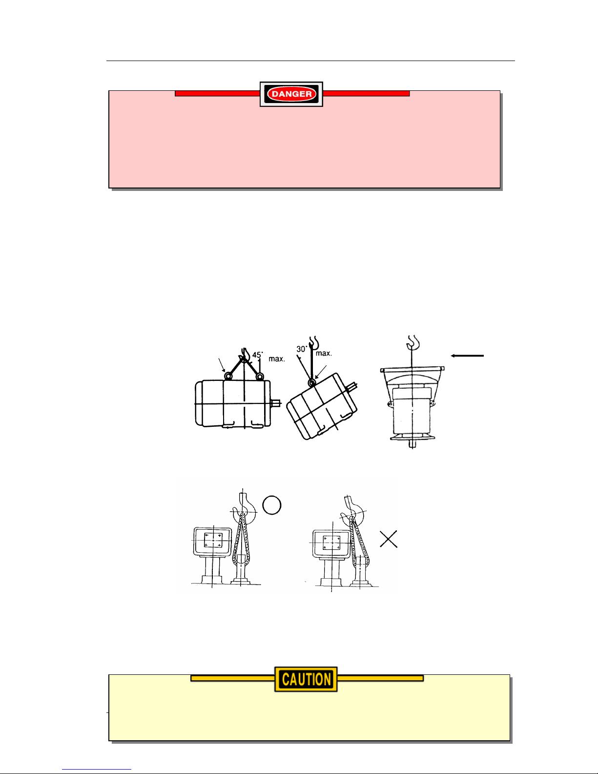
3.2.10. Points to note when hoisting:
a. Do not twist steel wires.
b. Make sure eye bolts have been firmly screwed in.
c. Keep the sling vertical when moving/lifting motor.
Fig. 1
Please keep the sling vertical when lifting / moving the motor.
Fig. 2
An accident could occur if the motor eyebolt/lifting hook is overloaded.
They are suitable for the motor weights only.
Do not lift motor and load combined with motor lifting hook.
Motor is fitted with lifting points (arrowed). These points are designed to lift
motor weight only.
Do not use other hooks or handles to lift motor.
Page 9
Teco Installation and Maintenance Manual
TEFC Squirrel Cage Induction Motors
Teco Electric and Machinery Company
Manual Number: IOM ~ TEFC Rev.01
9
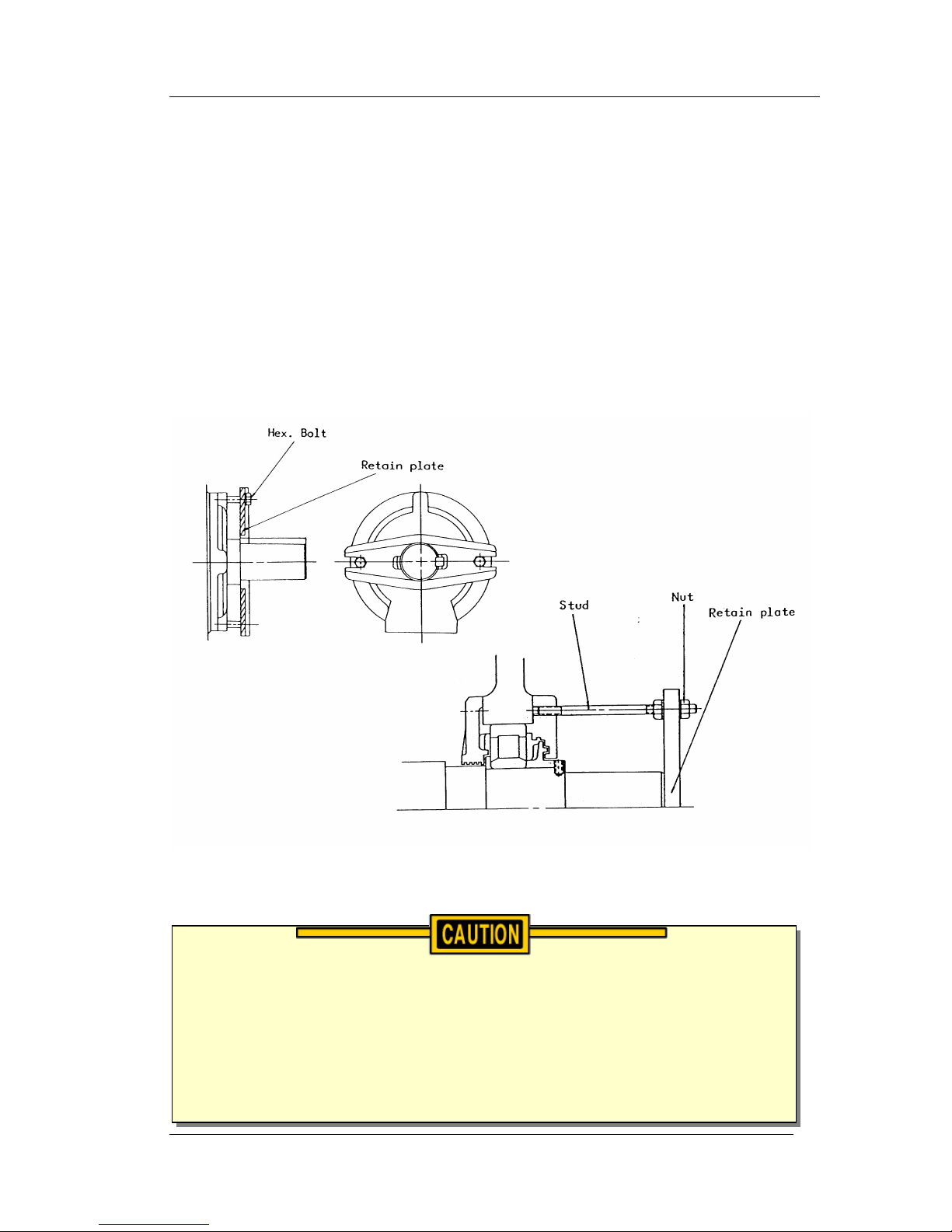
3.3. TRANSPORTATION
To keep the rotating parts of motor from moving, thus causing damage
during Transportation, they should be held securely as follows:
3.3.1. Motors fitted with a retaining plate/bracket to secure the shaft must have it
fitted during transportation. Please retain this device for future
transportation of the motor.
3.3.2. After receiving motor, remove all securing studs, nuts, etc. before putting
motor into operation. (Fig.3)
Fig 3
Shaft Locks are fitted as standard and these should be fitted during
installation and should only be removed once the pulleys and guards are
ready to be fitted. The motor must not be transported without the shaft lock
fitted, damage to bearings caused by shaft locks being removed or moisture
ingress whilst awaiting commissioning is not covered under motor warranty.
Page 10

Teco Installation and Maintenance Manual
TEFC Squirrel Cage Induction Motors
Teco Electric and Machinery Company
Manual Number: IOM ~ TEFC Rev.01
10
3.4. INSTALLATION.
3.4.1. Site conditions for motor installation:
Standard site conditions for installation of motors are as follows:
a. Ambient temperature: -20
0
C~400C.
b. Humidity: Relative humidity below 90% RH for totally enclosed type.
c. Elevation: Below 1000 metres.
d. Should the installation be in an industrial zone, it should be free of explosive
gases and liquids.
e. Foundation should be strong so as not to induce vibration.
3.4.2. Ventilation and Space.
a. Installation should be well ventilated.
b. The area should be large enough to facilitate heat dissipation and
maintenance.
3.4.3. Foundation.
Use rigid and solid sole plate or common bed as the foundation.
3.5. MOUNTING.
3.5.1. An adequate motor support (which is the responsibility of others) is very
important. It must have sufficient rigidity to maintain alignment between
the motor and its driven load. Inadequate or improperly designed motor
supporting structures can lead to serious vibration and alignment problems.
3.6. COUPLING & ALIGNMENT.
Two pole motors and motors larger than Frame 315M must not be coupled to
the driven equipment by means other than direct connection.
Please refer to TECO if belt connection is to be used.
Page 11
Teco Installation and Maintenance Manual
TEFC Squirrel Cage Induction Motors
Teco Electric and Machinery Company
Manual Number: IOM ~ TEFC Rev.01
11
3.6.1. Installation.
Field application of a coupling to the motor shaft should follow the
procedures recommended by the coupling manufacturer. Under no
circumstances may the motor shaft be modified as to configuration or
diameter without the approval of Teco Australia. The motor shaft extension
must not be subjected to either extreme heat or cold during coupling
installation. If it is necessary to exert axial force on the shaft, either
continuously or intermittently, during coupling application, it must be
properly restrained axially to prevent bearing damage.
3.6.2. After the motor has been properly aligned with the driven equipment and
the hold down bolts have been installed and tightened, at least two dowel
pins should be installed diagonally opposite motor feet.
3.6.3 Alignment.
In aligning the motor (and rotor) axially with the driven equipment,
consideration should be given to the axial shaft expansion and increase in
shaft centre line height due to thermal effects.
Shaft height growth (change in shaft centre line elevation) for TEFC
machines can be calculated as follows,
Growth =(0.0005) x (motor foot to shaft centre line dimension [in mm]).
The exposed rotating parts should be covered to prevent accidents.
Motors must always be accurately aligned. Incorrect alignment can lead to
bearing failure, vibration and even shaft fracture. As soon as bearing
failure or vibration is detected, the alignment should be checked.
Page 12
Teco Installation and Maintenance Manual
TEFC Squirrel Cage Induction Motors
Teco Electric and Machinery Company
Manual Number: IOM ~ TEFC Rev.01
12
3.6.4 It is desirable, in normal operation that the motor operates, so that no axial
force is exerted on the coupling.
The motor shaft and the driven shaft should be aligned within the following
tolerances in both angular and parallel alignment (refer Table 1).
Units in mm
TIR
Total Indicated
Runout
Solid
Coupling
Flexible
coupling
Dimension C
Medium, Low speed up to 2500
RPM
0.04
0.05
High speed over 2500 RPM
0.03
0.03
Dimension A
Medium, Low speed up to 2500
RPM
0.03
0.04
High speed over 2500 RPM
0.03
0.03
Table 1
3.6.5 Angular misalignment is the amount by which the centre lines of the driver
and driven shaft are skewed. It can be measured using a dial indicator set
up as shown in fig 4. The couplings are rotated together through 360
degrees so that the indicator does not measure runout of the coupling hub
face. The shaft should be forced against either the in or out extreme of
their end float while being rotated.
Fig. 4 Fig. 5
3.6.6 Parallel misalignment is the amount by which the centre lines of the driver
and the driven shafts are out of parallel. It can be measured using the dial
indicator as shown in fig. 5. Again the couplings are rotated together
through 360 degrees so that the indicator does not measure runout of the
coupling hub outside diameter.
Page 13
Teco Installation and Maintenance Manual
TEFC Squirrel Cage Induction Motors
Teco Electric and Machinery Company
Manual Number: IOM ~ TEFC Rev.01
13
3.6.7 After the motor has been properly aligned with the driven equipment and
the hold down bolts have been installed and tightened, at least two dowel
pins should be installed diagonally opposite motor feet.
3.7. INSTALLATION FOR BELT DRIVE
3.7.1. Small, medium and large motors within frame sizes up to and including 315
frame are designed for use with belt transmission or direct coupling.
3.7.2. The diameter ratio between conveyance sheaves should not be greater 5 to
1 for flat belts, and 8 to 1 for V-belts. It is also advisable to limit the belt
velocity to under 35m/sec to limit belt abrasion and vibration. The smaller
the outer diameter of the V-belt sheave, the greater the shaft bending
stress will be. If bending stress is in excess of the shaft fatigue stress, the
shaft may break. If concerned please inform TECO of the size of the
sheaves and belt details for checking.
3.8. ELECTRICAL CONNECTIONS
3.8.1. The rated conditions of operation for the motors are as shown by the
nameplate. Within the limits given below, of voltage and frequency variation
from the nameplate values, the motor will continue to operate but with
Place the sheave and belt as close as possible to the motor body and
shaft shoulder to reduce the bending moment and improve shaft life.
Do not hammer the conveyance devices such as coupling, belt sheaves, chain
wheels, gears, pulleys etc. onto the motor shaft. Those shaft fitments should
be fitted and removed only by means of suitable devices. Heat shrinking may
be a better alternative to avoid damaging bearings and other components.
Page 14
Teco Installation and Maintenance Manual
TEFC Squirrel Cage Induction Motors
Teco Electric and Machinery Company
Manual Number: IOM ~ TEFC Rev.01
14
performance characteristics that may differ from those at the rated
conditions:
+/- 10% of rated voltage
+/- 5% of rated frequency
+/- 10% combined voltage and frequency variation so long as frequency
variation is no more than +/- 5% of rated value.
Operating the motor at voltage and frequencies outside of the above limits
can result in both unsatisfactory motor performance and damage to/or
failure of the motor.
3.8.2. Motor connections should be carried out in accordance with the details
applicable to the appropriate supply voltage as shown on the motor
nameplate and should be undertaken by suitably qualified personnel.
3.8.3. The main lead box furnished with the motor has been sized to provide
adequate space for the make up of the connections between the motor lead
cables and the incoming power cables.
3.8.4. The motors are provided with grounding pads and/or bolts for the
connection of earthing.
The bolted joints between the motor lead and the power cables must be
made and insulated in a workman-like manner following the best trade
practices and in accordance with the minimum requirements of the current
Australian Standards.
The motor must be grounded by a proper connection to the electrical
grounding system and in accordance with the minimum requirements of the
Australian Standards.
Motors fitted with insulated bearings and rotor grounding brushes which are
used on VVVF Drives must be effectively earthed to the supply system.
Page 15

Teco Installation and Maintenance Manual
TEFC Squirrel Cage Induction Motors
Teco Electric and Machinery Company
Manual Number: IOM ~ TEFC Rev.01
15
3.9. AUXILIARY DEVICES
3.9.1. Please refer to your specification and the motor nameplate to determine if
the motor is fitted with thermal winding protection devices.
The following are the most common:
One set (one per phase – total 3 off) of PTC winding thermistors.
Two sets (two per phase – total 6 off) of PTC winding thermistors.
One set (one per phase – total 3 off) of PT100 winding Resistance
Temperature Detectors (RTD’s).
Two sets (two per phase – total 6 off) of PT100 winding Resistance
Temperature Detectors (RTD’s).
3.9.2. Where specified motors may also be equipped with PT100 bearing
Resistance Temperature Detectors (RTD’s).
3.9.3. Thermistors are positive temperature coefficient type (1000 ohm @ tripping
temperature) refer to specification table for tripping temperature.
They are a tripping device only and not a temperature detector.
Thermistor leads should be connected to an appropriate thermistor control
relay from a reputable supplier.
3.9.4. RTD’s where fitted are of the platinum type (PT100) with a reference
temperature of 0°C at 100.
RTD leads should be connected to an appropriate motor protection system
from a reputable supplier.
Recommended temperature settings for RTD’s are as per table 2 below.
DEVICE
TYPE
LOCATION
ALARM
TRIP
RTD
PLATINIUM 100 @ 0OC
WINDING
1400C
1500C
RTD
PLATINIUM 100 @ 0OC
DE & NDE BEARING
900C
950C
Table 2
Page 16

Teco Installation and Maintenance Manual
TEFC Squirrel Cage Induction Motors
Teco Electric and Machinery Company
Manual Number: IOM ~ TEFC Rev.01
16
3.9.5. Where specified motors may be equipped with internal space heaters (check
for nameplate), to prevent the ingress of moisture into the motor insulation
system whilst motor is idle.
The incoming supply to the heaters should be in accordance with the details
contained on the heater nameplate.
The heater circuit should be inter-locked with the motor starter so as to de-
energise heaters when the motor is running.
Thermistors and/or RTD’s should not be meggered or tested at a
voltage above 2.5Volts.
Anti Condensation Heaters may be LIVE when the motor is switched
off. Isolate supply at all times before working on the motor.
Should the motor thermal protection circuit trip indicating over
temperature the cause/s should be thoroughly investigated before a
restart is attempted.
Failure to do so may lead to permanent damage or failure of the motor.
Page 17

Teco Installation and Maintenance Manual
TEFC Squirrel Cage Induction Motors
Teco Electric and Machinery Company
Manual Number: IOM ~ TEFC Rev.01
17
Chapter 4: OPERATING INSTRUCTIONS
4.1. EXAMINATION BEFORE START.
4.1.1. After motor is installed the following points should be noted:a. Check all wiring is correct and in accordance with connections appropriate to the
supply voltage as shown on motor nameplate.
b. Is the incoming cable size adequate?
c. Are all connections tight and properly insulated?
d. Check the rating of fuses, starter/contactor are correct & operating normally.
e. Check motor is correctly earthed especially if supplied via a VVVF drive.
f. Make sure starter/switches are set in correct position.
g. Check heater circuit if fitted is de-energised when motor is in operation.
h. Check bearings are filled with the correct quantity and grade of grease.
4.1.2. Measurement of insulation resistance.
a. Rated voltage below 1000V, measure with 500VDC megger.
b. In accordance with IEEE-43 clause 9.3 standards, refer to following formula:
R (M) = > (Rated Voltage + 1) x 10
1000
c. If a new winding has a low insulation resistance reading moisture ingress is
generally the problem. Drying the winding through the proper application of
heat will normally increase the insulation resistance to an acceptable level.
Following are several accepted methods for applying heat to a winding:
i. If the motor is equipped with anti condensation heaters these can be can be
energised to heat the winding.
ii. Direct current (as from a DC welder) can be passed through the winding. The
total current should not exceed approximately 50% of rated full load current.
Delta wound motors have six leads and the three phases should be connected
into one series circuit.
iii. Heated air can be either blown directly into the motor or into a temporary
enclosure surrounding the motor. The source of heated air should preferably
Page 18

Teco Installation and Maintenance Manual
TEFC Squirrel Cage Induction Motors
Teco Electric and Machinery Company
Manual Number: IOM ~ TEFC Rev.01
18
be electrical as opposed to fuelled (such as kerosene) where a malfunction of
the fuel burner could result in carbon deposits entering the motor.
iv. Insulation resistance measurements can be made while the winding is being
heated. However, they must be corrected to 400C for evaluation since the
actual insulation resistance will decrease with increasing temperature. As an
approximation for a new winding, the insulation resistance will approximately
halve for each 100C increase in insulation temperature above the dew point
temperature.
d. Should the resistance fail to attain the specified value even after drying,
careful examination should be undertaken to eliminate all other possible
causes, if any.
4.1.3. Power Supply
a. Is the capacity of the power supply adequate?
b. Do voltage and frequency of supply match with those on the nameplate?
c. Voltage variation should be confined to within +/-10% of the rated value
and the phase to phase voltages should be balanced.
Caution must be exercised, when heating the motor with any source
of heat other than self-contained space heaters, to raise the
winding temperature at a gradual rate to allow any entrapped
moisture to vaporise and escape without rupturing the insulation.
The entire heating cycle should extend over 15-20 hours.
Ensure adequate guarding is provided so live parts cannot be touched.
Page 19

Teco Installation and Maintenance Manual
TEFC Squirrel Cage Induction Motors
Teco Electric and Machinery Company
Manual Number: IOM ~ TEFC Rev.01
19
4.1.4. Bearing Lubrication
Grease Lubricated Type.
a. Refer to the section “Maintenance of Bearing” for maintenance procedures
and grease type.
4.1.5. Other Points to note
a. Make sure the transmission system, including belts, screws, bolts, nuts and
set pins are in good condition.
b. Dismantle all locks which fasten the moveable parts of the motor during
transportation, and turn the shaft by hand (if practical) to check if it moves
freely.
c. Check if there is any evidence of foreign matter inside the motor before
starting.
d. Make sure the items above are examined. Test the motor with or without
load. Record and check according to “Maintenance” at 15 minute intervals
during the first three hours of operation. Then conduct regular examinations
after longer intervals. If problems are experienced test without load to
ascertain whether it is a load, structure, alignment or motor issue.
4.2. STARTING OPERATION.
4.2.1. Starting Load.
The initial test involves running the motor without load. Unless specified, a
motor is designed to start with light load, which is then gradually increased
to full load, as the motor accelerates to full speed.
4.2.2. Starting.
The bearings are initially lubricated with the correct grade of grease at
the factory. After installation, long storage and at initial start
up/commissioning the bearings must be fully purged with new grease.
Please refer to section 7.
Page 20

Teco Installation and Maintenance Manual
TEFC Squirrel Cage Induction Motors
Teco Electric and Machinery Company
Manual Number: IOM ~ TEFC Rev.01
20
a. Motor can be restarted if the initial start fails. Three attempts are
permissible when the motor is at ambient (cold) temperature. Two starts in
succession are permitted when motor is at normal running temperature.
Smaller motors have a more frequent starting cycle.
b. Should an additional start be necessary beyond the conditions stated above,
the following restrictions should be noted:
i. Let the motor cool down for 60 minutes before a full load restart.
ii. Let the motor cool down for 30 minutes before a no load restart.
iii. Two inching starts can be regarded as one normal start.
c. If the motor rotor fails to start turning after two seconds, shut off power
supply immediately. This can result from:
i. Too low a voltage at the motor terminals.
ii. The load is too large for motor rating.
iii. The load has seized mechanically.
iv. Electrical connections incorrect.
v. Single phase power has been applied.
vi. Any combination of the above.
Note – Investigate thoroughly and take corrective action before attempting a
restart.
4.2.3. Direction of Rotation.
a. Motors are generally bi-directional. Some 2 pole and low noise motors are
uni directional only. If motor is uni-directional the fan cowl will be fitted with
a direction of rotation arrow.
b. If direction of rotation must be changed on a bi-directional motor, cut
power and wait until the motor stops, then interchange any two of the three
incoming phase leads.
4.2.4. Power Supply. Voltage/Current.
a. Check if the voltage and frequency of the power supply are identical to that
shown on the nameplate.
Page 21

Teco Installation and Maintenance Manual
TEFC Squirrel Cage Induction Motors
Teco Electric and Machinery Company
Manual Number: IOM ~ TEFC Rev.01
21
b. Voltage variation should be confined to within +/-10% of nameplate
voltage, and the three phase voltages should be balanced.
c. Check if the phase currents of the motor, without load, are within +/-5% of
the average values.
4.2.5. Frequency.
Frequency variation should be confined to within +/-5% of the nameplate
frequency. The aggregate variation of voltage and frequency should be
confined to within +/-10% of the absolute value of the rating.
4.2.6. Run Up Time.
4.3. CAUTIONARY POINTS TO NOTE:
4.3.1. Bearings:
a. The motor is fitted with grease lubricated bearings. Following initial start up
the bearing temperatures should be closely monitored. A rapid rate of rise
in bearing temperature is more indicative of impending trouble, however,
when greasing an expected higher temperature is normal and should
equalize after a period of time.
b. When the rate of bearing temperature rise is less than 1°C per half hour,
the bearing temperature is considered to be stabilised.
c. If the total bearing temperature exceeds 100°C, the motor should be shut
down immediately and subsequent checks be undertaken.
The Run Up time is longer for motors connected to a load with a large inertia.
However, if the run up time exceeds what is deemed normal or there is
abnormal noise, the motor and load should be examined to establish the
cause before attempting a restart.
Page 22

Teco Installation and Maintenance Manual
TEFC Squirrel Cage Induction Motors
Teco Electric and Machinery Company
Manual Number: IOM ~ TEFC Rev.01
22
4.3.2. Vibration:
a. The ideal values generally for motors are figures below 2.8mm/sec.
If vibration exceeds this level, an examination of the motor, load, structure
etc, should be made to determine the cause, the first check to undertake
would be to run the motor un-coupled and check if the vibration is still
evident, see section 5.4 Vibration.
4.3.3. Starting:
a. If the motor acceleration time exceeds the typical ramp time for this
application, shut off the power immediately.
Investigate thoroughly and take corrective action before attempting to
restart.
b. It should be recognised that each start of an induction motor subjects the
motor to current greater than full load current with resulting heating of the
stator and rotor windings. Each start can produce more heat than is
produced and dissipated by the motor under a full load condition.
c. The starting duty for which the motor is designed must not be exceeded if
long motor life is expected. Abnormally low terminal voltage and/or
excessive load torque during motor start up can cause lengthened
acceleration times during which the rotor ventilation is reduced. This can
cause rotor damage or lead to shortened rotor life.
Page 23

Teco Installation and Maintenance Manual
TEFC Squirrel Cage Induction Motors
Teco Electric and Machinery Company
Manual Number: IOM ~ TEFC Rev.01
23
Chapter 5: ROUTINE MAINTENANCE
5.1. IMPORTANCE OF DAILY INSPECTION.
5.1.1. Normally electric motors do not fail suddenly. It happens over time, and
regular inspection will detect a problem before a serious situation develops.
If operators in the plant are alert, faults can be detected early and action
taken to eliminate trouble.
Daily inspection, can be performed without interrupting the end user’s
normal operation.
5.1.2. Do not overlook any minor irregularities. If necessary, stop the machine
immediately to check and repair. Essentially, inspections should be
performed by the operator daily. But a maintenance technician should also
check the machine once a week together with the operator.
5.2. POINTS TO NOTE WHEN STARTING.
a. Check power supply to see if voltage and frequency are normal.
b. Is starter set at starting position?
c. Are there sparks during start?
d. Is the motor accelerating normally?
5.3. TEMPERATURE RISE.
5.3.1. The temperature of a motor is often determined by measuring the
temperature of the frame. This is not indicative of actual internal
winding operating temperature, however, this method can often be
referred to and compared with previous readings. If the temperature is
found to be higher than usual please check the following possibilities.
DO NOT MAKE TEMPERATURE READINGS WITH THE SENSE OF TOUCH.
Often the temperature of a motor is determined by touch. Human hands can only
tolerate temperatures below 600C. Most motors safely operate at temperatures
greater than this, therefore, the sense of touch should not be used. Temperature
readings by hand are also inaccurate. Readings should be made using a
thermometer probe or non-contact infra red thermometer.
Page 24

Teco Installation and Maintenance Manual
TEFC Squirrel Cage Induction Motors
Teco Electric and Machinery Company
Manual Number: IOM ~ TEFC Rev.01
24
5.3.2. Main causes of high temperature:
a. Motor Conditions
i. Voltage and frequency variation of power source is in excess of
tolerance.
ii. Unbalanced three phase voltage, open circuit or poor contact.
iii. Insufficient or excessive lubrication.
iv. Abnormal frequency of starts.
v. Single-phasing due to open circuit or short circuit.
vi. Damaged starter or improper operation.
vii. Blocked ventilation ducts.
viii. Motors cooling vents blocked.
b. Due to load or mechanical conditions:
i. Overload.
ii. Defective transmission coupling.
iii. Poor installation causing overload.
iv. High ambient temperature or radiant heat emitted from driven load
or surroundings.
5.4. VIBRATION.
5.4.1. Main causes inducing vibration:
i. Unbalanced load.
i. Misalignment of couplings.
ii. Unbalanced belt-sheaves.
iii. Improper couplings with belts or chains.
iv. Unsuitable foundation or poor installation.
v. Unbalanced motor rotor.
vi. Serious abrasion to motor or load machine drive bearing.
vii. Defective bearing or subsequent bearing damage.
5.4.2. No matter what causes the vibration, if it is not eliminated, the following
faults may develop:
i. Bearing damage.
Page 25

Teco Installation and Maintenance Manual
TEFC Squirrel Cage Induction Motors
Teco Electric and Machinery Company
Manual Number: IOM ~ TEFC Rev.01
25
ii. Deformation of shaft.
iii. Loose parts or couplings.
5.5. NOISE.
5.5.1. Points to Note.
Not all noise is the result of a fault or abnormality. For instance, wind and
slight electromagnetic sounds are perfectly normal. They will remain at the
same level no matter how long the motor is in operation. Generally the
louder the noise, the larger the vibration amplitude will be.
5.5.2. Bearing Sound.
i. Bearing noise is a guide to the condition of the motor bearings
without dismantling the motor.
ii. Normal bearing sound in general is continuous, not intermittent. The
sound may tend to increase with the age of the bearings, but its
increase is gradual and hardly noticeable by the ear.
iii. Abnormal bearing sound is intermittent, rarely continuous.
iv. Some motors will emit noise when unloaded or after greasing due to
skating. This is normal and temporary.
5.5.3. Abnormal bearing sound generally develops from the following causes:
i. Foreign matter in grease.
ii. Scratches on the contact surface of the bearing.
iii. Rust on the contact surfaces of the bearing due to moisture ingress.
iv. Poor quality of grease or wrong type of grease.
v. Insufficient grease (the sound could be continuous).
5.5.4. Causes of abnormal electromagnetic sound:
i. Single phasing.
ii. Short circuit in windings.
iii. Unbalanced air gap resulted from serious bearing wear.
Page 26

Teco Installation and Maintenance Manual
TEFC Squirrel Cage Induction Motors
Teco Electric and Machinery Company
Manual Number: IOM ~ TEFC Rev.01
26
5.6. ODOUR.
5.6.1. Causes of motor odours:
i. Short circuit or over current causing overheating of varnish.
ii. Poor lubrication due to insufficient or contaminated grease.
5.7. MEASUREMENT OF THREE PHASE CURRENT.
5.7.1. Causes & effects
When load current is above the rating on the nameplate, it means the
motor may be overloaded. However, the cause of over current is not
confined to overloading, but may be caused by poor coupling installation,
transmission structure, excessive high or low voltage, etc.
a. Causes of unbalanced three phase current.
i. Unbalanced three phase voltage.
ii. Open circuit in power distribution lines.
iii. Poor switch contact.
iv. Open or short circuit in winding.
v. Open circuit at power transformer.
b. Effects:
i. Overheating of the windings causing fire or short circuit.
ii. Vibration of motor.
iii. Reduction of motor output torque.
c. Causes of wavering of ammeter indicator:
The characteristics of devices such as compressor or press are apt to cause
wavering of the indicator. Other causes are,
i. Poor contact of switches.
ii. Uneven mechanism.
iii. Unbalanced air gap due to serious bearing aberration.
iv. Broken conductors of squirrel cage rotor.
Page 27

Teco Installation and Maintenance Manual
TEFC Squirrel Cage Induction Motors
Teco Electric and Machinery Company
Manual Number: IOM ~ TEFC Rev.01
27
5.8. MOTOR APPEARANCE.
5.8.1. Reasons for Cleaning
a. Excessive dust or oil accumulation on the motor surface leading to the
clogging of ventilation channels between cooling ribs will reduce the motors
cooling efficiency.
b. Keeping the motor and equipment clean will improve appearance and
longevity.
Motors should never be cleaned or disturbed whilst the motor is in
operation.
Page 28

Teco Installation and Maintenance Manual
TEFC Squirrel Cage Induction Motors
Teco Electric and Machinery Company
Manual Number: IOM ~ TEFC Rev.01
28
Chapter 6: PERIODIC MAINTENANCE
6.1. REGULAR INSPECTION & MAINTENANCE.
6.1.1. Major points in regular inspection and maintenance:
a. Routine inspection and maintenance are usually performed by operators
with the sense of touch, sight, smell and simple meters. But it is difficult to
detect trouble such as insulation deterioration etc. unless the motor is
stopped and checked.
b. Replacement of worn-out parts will increase longevity and prevent
breakdown.
c. Regular inspection and maintenance is important in preventing breakdown
and lengthening service life.
c. Owing to the varied uses and environments motors are placed in, it is
difficult to set periods for regular inspection and maintenance. However, it
has to be performed at least once every 6 months. Generally, the inspection
time is determined by the following factors:
High temperatures may arise under operating conditions on the motor
surfaces, so that touching should be prevented or avoided.
Keep away from moving and live parts.
Unless deemed necessary, do not remove guards whilst assessing the
motor.
For safety, properly trained personnel must only carry out maintenance
and repairs.
Some testing, such as insulation resistance, usually requires the motor
to be fully stopped and isolated from any power supply/supplies.
Page 29

Teco Installation and Maintenance Manual
TEFC Squirrel Cage Induction Motors
Teco Electric and Machinery Company
Manual Number: IOM ~ TEFC Rev.01
29
i. Ambient conditions.
ii. Start and stop frequency.
iii. Trouble with components affecting motor functions.
iv. Parts which wear (eg. bearings).
v. The important position of a motor in operation of a factory, mine etc.
should be fully recognised. Therefore, its condition should be monitored,
especially when it is operating in severe conditions.
6.1.2. Motor Windings.
a. For measurement of insulation resistance and tests to determine quality of
insulation resistance, please refer to measures stated in Section 4.1.2.
b. Inspection of coil end:
i. Grease and dust accumulated on coil may cause insulation
deterioration and a reduction in cooling efficiency.
ii. Moisture.
iii. Discolouring from original colour. Overheating mainly causes this.
c. Stator wedges, is there any change from their original position?
d. Is the tie wire at the coil ends in correct position with no movement?
6.1.3. Bearings.
a. Please refer to section 7 for bearing maintenance.
6.1.4. Cleaning the interior of the motor.
a. After a motor has been in operation for some time, accumulation of dust,
carbon powder and grease etc., on the inside is unavoidable, and may
cause damage. The inside should therefore, be regularly cleaned and
examined to assure reliable performance.
b. Points to note during cleaning:
i. If using compressed air or a blower (Typically for squirrel cage only).
Compressed air should be free of moisture.
Maintain air pressure at 4kg/cm
2
, since high pressure can cause
damage to coils.
Page 30

Teco Installation and Maintenance Manual
TEFC Squirrel Cage Induction Motors
Teco Electric and Machinery Company
Manual Number: IOM ~ TEFC Rev.01
30
ii. Vacuum – Recommended for wound rotor/slip ring type.
Vacuum cleaning can be used, both before and after other methods of
cleaning, to remove loose dirt and debris. It is a very effective way to
remove loose surface contamination from the winding. Vacuum cleaning
tools should be non-metallic to avoid any damage to the winding insulation.
iii. Wiping.
Surface contamination on the winding can be removed using a soft, lint-free
cloth. If the contamination is oily, the cloth can moistened (not dripping
wet) with a safety type petroleum solvent. In hazardous locations, a solvent
such as inhibited methyl chloroform may be used, but must be used
sparingly and immediately removed. While this solvent is non-flammable
under ordinary conditions, it is toxic and proper health and safety
precautions should be followed while using it.
6.1.5. Clean the exterior of the motor.
a. The inlet air openings should not be allowed to accumulate any dirt,
dust, slurry, lint, etc. that could restrict free air movement.
b. Totally enclosed fan cooled motors require special cleaning
consideration. The external fan must be cleaned thoroughly since any
dirt build up not removed can lead to balance issues and vibration.
Solvents of any type should never be used on windings provided with
abrasion protection. Abrasion protection is a grey, rubber-like coating
applied to the winding end-turns.
Adequate ventilation must always be provided in any area where solvents
are being used to avoid the danger of fire, explosion or health hazards. In
confined areas (such as pits), each operator should be provided with an air
line respirator, a hose mask, or self-contained breathing apparatus.
Operators should wear goggles, aprons and suitable gloves. Solvents and
their vapours should never be exposed to open flames or sparks and
should always be stored in approved safety containers.
Page 31

Teco Installation and Maintenance Manual
TEFC Squirrel Cage Induction Motors
Teco Electric and Machinery Company
Manual Number: IOM ~ TEFC Rev.01
31
6.1.6. Checking motor installation and coupling.
a. Installation:
i. Is foundation solid?
ii. Are all bolts and/or nuts tight and in good order?
b. Coupling:
i. Is coupling in good order?
ii. Are fasteners tight and in good order?
6.2. CLEANING OF COILS, DRYING & VARNISHING TREATMENT.
Age, constant heating and cooling and other factors may cause insulation
deterioration. Also, salt deposits or grease may lower insulation resistance.
Steam cleaning, drying and re-varnishing may be necessary if the motor has
been flooded or showing deterioration from age.
6.2.1. Cleaning:
a. If the coils are slightly contaminated, compressed air, cloth or a nylon brush
can be used to do the cleaning. However, when contamination is serious,
thorough washing has to be performed. The cleaning methods are as
follows:
b. Cleaning with water:
i. This method is applicable to motors having been immersed in water or
insulated with no cotton yarn and paper materials.
ii. After washing, dry immediately.
iii. Cleaning with steam.
If the motor has been immersed in sea-water or a chemical solution, clean
with steam after washing thoroughly.
Steam pressure must be kept between 2 – 4 kg/cm
2
. High pressure may
cause insulation damage.
Motors should never be cleaned or disturbed whilst the motor is in
operation.
Page 32

Teco Installation and Maintenance Manual
TEFC Squirrel Cage Induction Motors
Teco Electric and Machinery Company
Manual Number: IOM ~ TEFC Rev.01
32
c. Steam temperature should be maintained between 50
0
C – 800C.
d. After cleaning, dry immediately.
6.2.3. Drying Method.
a. Application:
i. Drying after cleaning.
ii. Motor has absorbed moisture.
b. Hot air method (using heater and blower).
i. Parts to be dried are surrounded inside a steel plate leaving an inlet and an
outlet for hot air. Hot air will enter the inlet to dry parts (stator, rotor, etc.),
and will leave via the outlet carrying away moisture.
ii. The temperature within the area surrounded by the steel plate should be
maintained at 900C – 1000C.
c. Drying with infrared ray lamp:
i. Install the infrared ray lamp in a baking area surrounded with steel plate
with openings at the bottom.
ii. This method can cause partial overheating. So attention must be paid to the
parts heated and the temperature must be kept below 1000C.
d. Drying method with electric current:
i. The winding must have a minimum insulation resistance above 0.5MΩ
measured with 500VDC megger before using this method so as to avoid a
short circuit.
ii. Lock the rotor (short the secondary winding of the wound rotor motor),
apply rated voltage of approximately 5% - 10% to the winding.
iii. Temperature control settings:
Squirrel cage rotor induction motor: 700C – 800C for the stator.
e. Measurement of insulation resistance.
i. Measure the insulation resistance periodically during drying.
ii. At the initial stage of drying, insulation resistance may decline slightly.
When it returns to normal, the drying process is complete.
iii. When the current method is applied, be sure to turn off the power to
measure insulation resistance.
Page 33

Teco Installation and Maintenance Manual
TEFC Squirrel Cage Induction Motors
Teco Electric and Machinery Company
Manual Number: IOM ~ TEFC Rev.01
33
6.3. VARNISH.
Kind of Varnish
JIS-W-25 or W-28 are highly recommended.
a. Method of Varnish Treatment
i. Dipping method: Immerse windings completely into varnish until no
air bubbles appear.
ii. Pouring Method: Pour varnish completely over windings
Note: Let varnish drip to dry after dipping or pouring. Changing position of
the motor will obtain an even coverage.
b. Curing of Varnish
i. Set oven temperature at 110oC.
ii. Curing time should be 12 – 16 hours
iii. Ensure ventilation is adequate during curing. Combustible gases are
present.
To ensure adequate insulation the above procedure should be repeated.
6.4. KEY POINTS FOR MAINTENANCE & INITIAL OPERATION
INSPECTION AFTER LONG STORAGE.
6.4.1. If the motor has been out of service in excess of three months, careful
inspection should be made before putting the motor into operation again.
6.4.2. When the motor is not in operation, the following precautionary measures
should be undertaken:
The place for storage should be dry and well-ventilated. If the motor has to
be placed at work site for some time, it should be completely covered and
stored on pallets to prevent dust and moisture contamination.
Inspection and maintenance prior to storage.
Please refer to “Regular Inspection and Maintenance” (Section 6.1).
Page 34

Teco Installation and Maintenance Manual
TEFC Squirrel Cage Induction Motors
Teco Electric and Machinery Company
Manual Number: IOM ~ TEFC Rev.01
34
6.4.3. Items to be examined prior to initial operation.
a. Cleaning:
Outside of motor.
Motor interior.
b. Measurement of insulation resistance:
Measurement of insulation resistance and standards to determine quality if
Insulation resistance, please refer to measures stated in Section 4.1.2.
Measurement of insulation resistance.
6.4.4. Drying: If the motor has absorbed moisture, it must be dried.
6.4.5. Examination of bearings.
Turn the motor shaft by hand (if practical) to see if it rotates smoothly and
if there is any unusual noise.
6.4.6. Replenishment of grease. (Refer to bearing maintenance Section 7).
6.4.7. Switches and starters.
Clean off dust and any foreign matter etc.
Check if the operation is normal.
Are the moving parts functioning smoothly?
Check if all bolts and nuts are tight and in good order.
6.4.8. Examination and maintenance of standby motor.
Important: The purpose of a standby motor is to substitute as an
emergency motor if the motor in operation breaks down, this motor should
not be exposed to induced vibration whilst stationery.
It is important to always maintain the standby motor in top condition.
Maintenance should be performed strictly according to items and notes
stated previously.
Page 35

Teco Installation and Maintenance Manual
TEFC Squirrel Cage Induction Motors
Teco Electric and Machinery Company
Manual Number: IOM ~ TEFC Rev.01
35
6.5. RECORDS OF OPERATION AND MAINTENANCE.
6.5.1. Objective:
a. Fully understand the site conditions of the motor in operation and discover
any abnormalities in advance.
b. Prevent the neglect and act of maintenance.
c. Map pertinent maintenance plans after fully understanding the operation of
motor.
d. Assess the life of parts to determine the quantity of spare parts to be kept.
e. To plan the number of spare motors and replace or repair the motors in
operation according to a schedule.
6.5.2. Records of operation.
a. A maintenance card in table form is acceptable.
b. Principle contents:
i. Serial number of machine
ii. Model
iii. Three phase voltage
iv. Three phase current
v. Temperature of a motor in operation
vi. Ambient temperature, humidity, weather, date and time
vii. Time of start and stop
viii. Special remarks
ix. Operator’s name
Page 36

Teco Installation and Maintenance Manual
TEFC Squirrel Cage Induction Motors
Teco Electric and Machinery Company
Manual Number: IOM ~ TEFC Rev.01
36
6.6. POINTS TO NOTE ON DISASSEMBLY.
a. Disassemble according to the pre-set steps.
b. Necessary tools should be ready before disassembly.
c. Mark the disassembled parts so as to facilitate re-assembly.
d. Place parts, bolts and nuts etc, in a box to avoid misplacing.
e. Avoid damage to heavy parts during transportation.
f. Dust accumulation on coil-end, ducts etc., should be cleaned during
disassembly.
g. Coat parts with light oil.
h. Note if there is any shaft deflection or bearing damage when re-assembling.
i. Disassemble and assemble bearing according to the bearing maintenance
manual.
For safety and to prevent equipment damage properly trained
personnel must only carry out maintenance and repairs.
Page 37

Teco Installation and Maintenance Manual
TEFC Squirrel Cage Induction Motors
Teco Electric and Machinery Company
Manual Number: IOM ~ TEFC Rev.01
37
Chapter 7: BEARINGS
7.1. MAINTENANCE OF ROLLING BEARING.
7.1.1. General.
Bearings play a very important role in motor performance. It is essential to
keep bearings in good order for the motor to operate at optimum
performance. For this reason, please maintain bearings according to this
manual.
7.1.2. Motors within frame sizes D180 and below are complete with sealed for life
Bearings. (Unless the specification dictates these need to be re-greasible)
This type of bearing is a non maintainable item and has been pre packed
with grease and fitted with containment shields at point of manufacture.
These bearings do not require greasing for the life of the bearing.
7.1.3. Motors within frame sizes D200 and larger are equipped with through flush
greasing facilities.
Grease replenishment is required, if the motor has been out of service for 3
months or more and should also be carried out on initial start and at regular
intervals thereafter.
a. Replenishment of grease is recommended when the motor is running.
b. Clean the grease nipple and open the grease drain (if applicable) prior to
greasing. Restore after greasing.
c. A slight leakage of grease between the flinger and bearing cover is normal
and assists in totally sealing the bearing from ingress of dust and foreign
matter.
Whilst Motors are installed awaiting commissioning they must be adequately
protected against the elements, all external components in particular the shaft
extension and external labyrinth seals at the drive end must be fully covered
to avoid water ingress entering the motor body whilst stationery.
Please ensure that both the non drive end and drive end antifriction bearings
are fully purged with sufficient grease at first start up/commissioning
with the recommended grade and quantity of grease.
Page 38

Teco Installation and Maintenance Manual
TEFC Squirrel Cage Induction Motors
Teco Electric and Machinery Company
Manual Number: IOM ~ TEFC Rev.01
38
7.1.4. Grease Lubricated Type.
Keeping the bearing lubricant in top condition is extremely important in the
maintenance of bearings. It is a prerequisite of extended bearing life to
replenish grease using the correct grade, quantity and time interval, please
do not mix different types of grease.
The reasons for grease replenishment are:
a. Assure the rolling contact surface has no metal to metal contact.
b. Form a lubrication membrane on the rolling contact surface to reduce noise.
c. Purge the motor of old and contaminated grease, please ensure that the
grease in the discharge chute is pliable and will allow new grease to enter.
d. The presence of the correct grade and quantity of grease reduces corrosion,
protects and seals the bearing and lowers vibration.
7.1.5. Grease replenishment period:
The life of grease varies depending on model, speed, temperature,
operational conditions etc., it is, therefore, impossible to determine the
exact time interval for replenishment.
However, under normal conditions the greasing interval is shown in Table 3
can be used as a guide.
Page 39

Teco Installation and Maintenance Manual
TEFC Squirrel Cage Induction Motors
Teco Electric and Machinery Company
Manual Number: IOM ~ TEFC Rev.01
39
Bearing
Number
Speed(RPM)
600
720
750
900
1000
1200
1500
1800
NU2XX
14
14000
12500
12000
10500
9500
8000
6000
4500
NU3XX
15
13500
12000
11500
11000
9000
7000
5500
4000
16
13000
11500
11000
9500
8500
6500
5000
3500
17
12500
11000
10500
9000
8000
6000
4500
3000
18
12000
10500
10000
8500
7500
5500
4000
2500
20
11000
9500
9000
7000
6000
4500
3000
2000
22
10000
8500
8000
6000
5500
4000
2500
1500
24
9000
7500
7000
5500
4500
3500
2000
1500
26
8500
7000
6500
5000
4000
3000
1500
1000
28
8000
6000
6000
4500
3500
2500
1000
500
30
7000
5500
5500
4000
3000
2000
1000
500
32
6500
5000
5000
3500
2500
1500
500
500
34
6000
4500
4500
3000
2500
1500
500 36
5500
4000
4000
2500
2000
1000
500 38
5000
4000
3500
2500
1500
1000
500 40
5000
3500
3000
2000
1500
1000
44
4000
3000
2500
1500
1000
500
48
3500
2500
2500
1000
1000
500
Table 3.
Remarks:
a. Please refer to lubrication nameplate fitted and follow the
recommended schedule stated.
Bearing
Number
Speed(RPM)
600
720
750
900
1000
1200
1500
1800
3000
3600
62XX
10
19000
18000
17500
16500
15500
14500
12500
11000
6000
4500
63XX
12
18000
17000
16500
15000
14500
13000
11000
9000
4500
3500
72XX
13
17500
16500
16000
14500
14000
12000
10000
8500
4000
3000
73XX
14
16500
15500
15000
13500
12500
11000
9000
7000
3500
2500
15
16500
15500
15000
13500
12500
11000
9000
7000
3000
2000
16
16000
15000
14500
13000
12000
10500
8500
6500
2500
1500
17
16000
14500
14000
12500
11500
10000
8000
6000
2500
1500
18
15500
14000
13500
12000
11000
9500
7500
5500
2500
1500
20
14500
13000
12500
11000
10000
8500
6000
4500
22
13500
12000
11500
10000
9000
7500
5500
4000
24
13000
11500
11000
9000
8000
6500
4500
3500
26
12000
10500
10000
8500
7500
6000
4000
3000
28
11500
10000
9500
8000
7000
5500
3500
2500
30
11000
9500
9000
7000
6500
4500
3000
2000
32
10500
8500
8500
6500
5500
4000
3000
2000
34
10000
8000
8000
6000
5500
4000
2500
1500
36
9500
7500
7500
5500
5000
3500
38
9000
7000
7000
5000
4500
3000
Page 40

Teco Installation and Maintenance Manual
TEFC Squirrel Cage Induction Motors
Teco Electric and Machinery Company
Manual Number: IOM ~ TEFC Rev.01
40
b. The data as shown in Table 3 and/or lubrication nameplates are the
maximum recommended intervals under good conditions, please
consider site conditions, as a shortening of these periods may be
necessary.
7.1.6. Type of grease:
TECO motors can utilise different types of grease including Shell Gadus &
Mobil Polyrex EM Grease which has been selected based on the proposed
application.
Please check on the lubrication nameplate to confirm the type of grease
installed. Please use identical grease when servicing or alternatively
lubricants of different brands that have been established as being
equivalent in the areas of composition, physical properties and thickeners.
7.1.7. Amount of grease replenishment:
Amount of grease replenishment depends on the type, size and construction
and the bearings. For the maximum quantity used in one replenishment of
each bearing, as a guide, please refer to Table 4.
Please refer to lubrication nameplate fitted and follow the recommended
quantity stated.
7.1.8. Key points to note with grease filling:
Filling method for grease relief type bearing.
Use a good quality grease gun to pump grease through the grease nipple
into the bearings. The old contaminated grease is forced to drain out of the
discharge chute. While greasing it is recommended that the greasing
procedure is undertaken whilst the motor is running. The discharge outlet
may not be visible on some models, grease should be pumped in at the
recommended quantity and the sound of bearing should return to normal.
It is advisable to grease when the motor is operating as old grease is
expelled more easily.
Page 41

Teco Installation and Maintenance Manual
TEFC Squirrel Cage Induction Motors
Teco Electric and Machinery Company
Manual Number: IOM ~ TEFC Rev.01
41
Bearing No.
Amount of
replenishment
Bearing No.
Amount of
replenishment
62XX
72XX
NU2XX
222XX
6210
30g
63XX
73XX
NU3XX
223XX
6310
40g
6212
40
6312
60
6213
50
6313
80
6214
50
6314
80
6215
60
6315
100
6216
60
6316
100
6217
80
6317
120
6218
80
6318
120
6220
100
6320
160
6222
120
6322
220
6224
120
6324
270
6226
140
6326
300
6228
160
6328
400
6230
180
6330
450
6232
200
6332
500
6234
250
6334
600
6236
300
6336
700
6238
350
6338
800
6240
400
6340
900
6244
450
6344
900
6248
500
6348
900
Table 4.
*Fill new grease until it displaces the old grease completely.
Do not grease the motor whilst it is at standstill. If there is a draw-out
device for grease, draw out the used grease after greasing, please leave
excess grease on the rake as this will further protect the exit port from
moisture entry.
7.1.9. Temperature of bearing.
Temperature of the bearing will rise slightly, but this is temporary while
greasing and will return to normal a few minutes after greasing. Brief
temperature variations are of no concern, grease should be pumped in
sparingly to avoid excess temperatures being experienced.
WARNING
Stay clear of rotating parts while relubricating motor when it is in
operation.
Page 42

Teco Installation and Maintenance Manual
TEFC Squirrel Cage Induction Motors
Teco Electric and Machinery Company
Manual Number: IOM ~ TEFC Rev.01
42
7.1.10. Selection of grease gun.
There are two types of grease gun. High pressure lever type and hand press
type. As the hand press type has a lower force, grease replacement will
take more time. Greasing can be achieved quickly by using a lever type gun,
however, care should be taken to adjust the pressure and rate to avoid
excessive grease entry which may enter the motor’s interior.
7.2. NOISE OF BEARING.
a. Normal noise.
Noise is congenital to movement of the bearing. Generally bearing noise
that has a continuous rhythm with no sudden change is normal.
b. Abnormal noise.
It is difficult to detect the early stages of bearing failure with the human
ear. It takes a lot of experience and a sharp ear to detect abnormal noise.
Any sudden change in bearing noise should be investigated. Motors with
roller bearings at the drive end can emit more rotational noise than a ball
bearing and it is normal to hear skating/skidding of the rolling elements.
7.3. VIBRATION.
If the vibration of the bearing is unusually high, please test with vibroscope.
The preferred level for vibration should be below 2.8mm/sec. If the values
exceed this figure, an investigation should be undertaken to find and rectify
the problem.
7.4. REGULAR INSPECTION.
7.4.1. Regular monthly inspection.
Grease replenishment (refer to Section 7.1) and the motor lubrication plate.
Page 43

Teco Installation and Maintenance Manual
TEFC Squirrel Cage Induction Motors
Teco Electric and Machinery Company
Manual Number: IOM ~ TEFC Rev.01
43
7.4.2. Regular yearly inspection.
It is important to undertake regular inspection every year when the machine
is out of service for maintenance.
7.4.3. Inspection Notes.
a. Electrical etching.
When there are dark spots on bearing surface or outside the face of outer
ring and / or inside face of bearing housing, please check with a microscope
to see if they look like pock marks or fish scales which could be the result of
electrical etching due to poor installation etc.
b. Motors on VVVF Drives.
All TECO motors are suitable for running on VVVF drives, however, this does
depend on the application, kilowatt demand and speed range. TECO
recommend that when motors of 280/315 frame and above be fitted with at
least an insulated bearing at the non drive end and rotor grounding brush
fitted at the drive end, this is not categorical that this feature must be fitted,
purely a recommendation based on TECO’s experience, please consult with
the engineering specification whether the motor supplied requires this
feature.
c. Precision of installation.
The degradation of the bearing may be the result of misalignment due to
sinking foundations etc, after the motor has been in use for a long period.
Regularly check and record the alignment of couplings, and make
adjustments as necessary.
The bearing is a high precision component, it is important to avoid ingress
of dust, moisture and foreign matter. A hammer or similar object must not
be used during the cleaning and installation of the bearing.
Page 44

Teco Installation and Maintenance Manual
TEFC Squirrel Cage Induction Motors
Teco Electric and Machinery Company
Manual Number: IOM ~ TEFC Rev.01
44
Chapter 8: Troubleshooting.
8.1. FAULT FINDING & RECOGNITION
Kind of
Fault
Symptom
Cause
Remedy
Fail to
start without
load
Motionless
And soundless
Power-off
Consult power
company
Switch-off
Switch-on
No fuse
Install fuse
Broken wires
Check wires and
repair
Broken lead
Check leads and
repair
Faulty winding
Check winding and
repair
Fuse blowing –
(Circuit Breaker
trips off, slow
start with
electromagneti
c noise
Short circuit
Check circuit
Incorrect wiring
Check wiring
Poor contact in circuit
switches
Check and repair
Broken wiring
Check and repair
Poor contact of
starting switch
Check and repair
Incorrect connection
of starting switch
Check and repair
Overload
after start
Fuse blowing –
Fail to restart
due to circuit
breaker
tripping
Insufficient capacity
of fuse or breaker
Replace fuse or
breaker
Overload
Lighten load
High load at low
voltage
Check circuit
capacity and reduce
load
Page 45

Teco Installation and Maintenance Manual
TEFC Squirrel Cage Induction Motors
Teco Electric and Machinery Company
Manual Number: IOM ~ TEFC Rev.01
45
Kind of Fault
Symptom
Cause
Remedy
Overload after start
Overheating
of Motor
Overload or
Intermittent
Overload
Lighten Load
Under-voltage
Check circuit capacity
and power source
Over-voltage
Check power source
Ventilation duct
clogged
Remove the foreign
matter in the duct
Ambient
temperature
exceeds 450C
Lower ambient
temperature
Friction between
rotor and stator
Repair
Fuse blowing
(Single phase
rotating)
Install the specified
fuse
Poor contact of
circuit switches
Check and repair
Poor contact of
starting switch
Check and repair
Unbalanced three
phase voltage
Check circuit or
consult power
company
Speed falls
sharply
Voltage drop
Check circuit and
power source
Sudden overload
Check machine
Single phase
rotating
Check circuit and
repair
Switch overheat
Insufficient
capacity of switch
Replace switch
High load
Lighten load
Page 46

Teco Installation and Maintenance Manual
TEFC Squirrel Cage Induction Motors
Teco Electric and Machinery Company
Manual Number: IOM ~ TEFC Rev.01
46
Kind of Fault
Symptom
Cause
Remedy
Overload after
start
Bearing Overheat
Misalignment
between motor
and load
Re-align
Not enough
grease
Fully purge
bearings with
grease
High bearing
noise
Replace damaged
bearing
Noise
Electro-magnetic
noise induced by
electricity
Occurrence from
first operation
Check noise not
normal
Sudden sharp
noise and
smoking
Short circuit of
windings. Repair.
Bearing noise
Not enough
grease
Fully purge
bearings with
grease
Deterioration of
grease
Clean bearing
and re-grease
Excessive noise
Replace the
damaged bearing
Mechanical noise
caused by
machinery
Loose belt sheaf
Adjust key and
lock the screw
Loose coupling
Adjust the
position of
couplings and
tighten
Loose screw
Tighten screw
Fan rubbing
Adjust fan
position
Page 47

Teco Installation and Maintenance Manual
TEFC Squirrel Cage Induction Motors
Teco Electric and Machinery Company
Manual Number: IOM ~ TEFC Rev.01
47
Kind of Fault
Symptom
Cause
Remedy
Noise
Mechanical noise
caused by
machinery
Rubbing as a result
of ingress of
foreign matter
Clean motor
interior and
ventilation ducts
Wind noise
Noise induced by
air flowing through
ventilation ducts
Induced by
conveyance
machine
Repair machine
Vibration
Electro-magnetic
vibration
Short circuit of
windings
Repair
Open circuit of
rotor
Repair
Vibration
Unbalanced rotor
Repair
Unbalanced fan
Repair
Mechanical
vibration
Broken fan blade
Replace fan
Un-symmetrical
centres between
belt sheaf
Align central points
Central points of
couplings do not lie
on the same level
Adjust the central
points of couplings
on the same level
Improper mounting
installation
Lock the mounting
screw
Motor mounting
bed is not strong
Reinforce mounting
bed
Remarks:
i. Circuit switches: This includes knife switch, electromagnetic switch, fuse and
other connection switches etc.
ii. Starting switches: This includes Delta-Star starter, compensate starter,
reactance starter, resistor starter, starting controllers etc.
 Loading...