

TECO A510-2010-H3, A510-2020-H3, A510-2002-H, A510-2015-H3, A510-2003-H Instruction Manual
...Page 1

Page 2

I
Contents
Chapter 0...................................................................................................................0-1
0.1 Foreword......................................................................................................0-1
Chapter 1 Safety precautions..................................................................................1-1
1.1 Before supplying power................................................................................1-1
1.2 Wiring...........................................................................................................1-2
1.3 Before operation...........................................................................................1-2
1.4 Parameters setting.......................................................................................1-3
1.5 Operation.....................................................................................................1-3
1.6 Maintenance, Inspection and Replacement.................................................1-5
Chapter 2 Model Description...................................................................................2-1
2.1 Nameplate Data...........................................................................................2-1
2.2 Model Designation .......................................................................................2-1
Chapter 3 Ambient Environment And Installation.................................................3-1
3.1 Environment.................................................................................................3-1
3.2 Installation....................................................................................................3-3
3.2.1 Installation space...............................................................................3-3
3.2.2 External view of the product and warning label information...............3-4
3.2.3 Product Dismounting..........................................................................3-7
3.2.3.1 Standard type ..........................................................................3-7
3.2.3.2 Built-in filter type (440V 1 ~60HP)..........................................3-11
3.3 Wiring the peripheral devices of the inverter and related cautions.............3-13
3.4 Terminal Description..................................................................................3-17
3.5 Internal wiring diagram of main circuit........................................................3-22
3.6 Instrument for main circuit wiring and caution............................................3-23
3.7 Inverter Specifications................................................................................3-28
3.8 Overall Dimension drawing ........................................................................3-36
3.8.1 Standard Model................................................................................3-36
3.8.2 Built-in filter model (440V 1~60HP) .................................................3-40
Chapter 4 Software Index........................................................................................4-1
4.1 Keypad Description......................................................................................4-1
4.1.1 Panel Functions..................................................................................4-1
4.1.2 Display Description............................................................................4-2
4.1.3 LED Functional structure of LED seven-segment display..................4-4
4.1.4 Example of keypad operation.............................................................4-6
4.1.5 Operation Control...............................................................................4-8
4.2 Parameters list.............................................................................................4-9
4.3 Description of Parameter Functions...........................................................4-52
4.4 Description of Built-in PLC Function.........................................................4-210
4.4.1 Basic command .............................................................................4-210
Page 3

II
4.4.2 Basic command function................................................................4-211
4.4.3 Application command.....................................................................4-212
Chapter 5 Trouble Diagnosis and shooting...........................................................5-1
5.1 General........................................................................................................5-1
5.2 Fault detection function................................................................................5-1
5.3 Warning / self-diagnosis detection function..................................................5-5
5.4 Auto-tuning error........................................................................................5-11
5.5 PM motor auto-tuning error.........................................................................5-12
Chapter 6 Peripheral devices and option...............................................................6-1
6.1 List of braking resistor and braking detection module..................................6-1
6.2 AC reactor....................................................................................................6-3
6.3 Harmonic Filter.............................................................................................6-4
6.4 Noise filter....................................................................................................6-7
6.5 Output filter specification............................................................................6-10
6.6 Input power side Fuse specification...........................................................6-11
6.7 PG speed feedback card............................................................................6-12
6.8 Other..........................................................................................................6-14
6.9 Communication Interface Module (in development)...................................6-16
Appendix.....................................................................................................Appendix-1
Page 4

0-1
Chapter 0 Foreword
0.1 Foreword
To make full use of the inverter functions and ensure your safety, please read this
manual carefully. In case of any problems found in use, please contact local dealer or the
company's technical staff, our professionals will be happy to help you.
※ Caution on use
Inverter is a precision electronic product. For protecting your life and property, this
manual has been marked with "Warning", "Caution" to remind you of the safety precaution
issues in handling, installation, use and inspection. Please comply with it.
Warning
Inproper operation might cause serious personal injury.
Caution
Inproper operation might cause damage of inverter or
mechanical system.
Warning
¾ Avoid electrical shock! Since the DC capacitors inside the inverter discharges
completely in 5 minutes after the power supply is removed, please
disassemble or inspect it after 5 minutes when the power supply is removed.
¾ Wiring is not allowed when the power is supplied. Do not inspect the circuit
board when the inverter is in operation.
¾ Do not ass embly/disassemble or replace the internal wiring or circuit and parts
of the inverter by yourself.
¾ Make sure the earth terminal of the inverter is properly grounding.
Caution
¾ Do not carry out the dielectric voltage withstand test on the internal parts of
the inverter because they are easily damaged by high voltage.
¾ Connecting U/T1,V/T2 and W/T3 of inverter terminal to AC power is strictly
prohibited.
¾ CMOS integrated circuits of inverter circuit board are easily affected and
damaged by static electricity. Do not touch the circuit board.
Page 5

1-1
Chapter 1 Safety Precautions
1.1 Before supplying power
Warning
¾ The main circuit must be properly wiring. Single phase( R/L1, S/L2)/3-phase(R/L1,
S/L2, T/L3) are the input terminal of the power, which must not be mixed with
U/T1,V/T2 and W/T3 on use. In case of mixed use, supplying power will damage the
inverter.
Caution
¾ The power voltage must be the same as the input voltage of the inverter.
¾ When handling the inverter, do not draw the front cover directly. It is suggested to
handle the inverter body so as to prevent the front cover breaks off, avoiding the
inverter falling and causing injury or inverter damage.
¾ Please mount the inverter on noncombustible materials such as metal. Mounting on or
near the flammable materials is not allowed in case fire happened.
¾ If several inverters are mounted on a single control panel, the extra cooling fan shall
be added, so as to make the panel temperature below 40 ℃ and to prevent
overheating or fire.
¾ Please firstly turn off the power before disassemble or assemble the operator. Fix the
operator according to the indicating diagram to avoid operation failure or no display
due to improper operation.
Warning
¾ This product has passed the application level at IEC 61800-3 restricted areas. When
the product is used in some environments, there might be electromagnetic
interference. Therefore, appropriate test is recommended to be carried out before use
and grounding must be well done.
Caution
¾ Installation and use of the product must be conducted by a qualified professional
electrician.
¾ The product installation must be applied by the means of fixed wiring.
Page 6

1-2
1.2 Wiring
Warning
¾ Always turn OFF the input power supply before inverter installation or wiring terminals,
so as to avoid electric shock or fire.
¾ Wiring must be performed by an authorized person qualified in electrical work, to
avoid electric shock or fire.
¾ Make sure the grouding terminal is well grounded. (220 V class: Grounding
impedance shall be less than 100Ω, 460 V class: Grounding impedance shall be less
than 10Ω)
¾ Always test the operation of any emergency stop circuits after wiring. (Wiring is the
responsibility of the user.)
¾ Never touch the input/output lines directly with your hands or allow any line to contact
the Inverter case. Never short the circuits.
¾ Do not carry out the dielectric voltage withstand test on the inverter, which will cause
the semiconductor parts damage easily.
Caution
¾ Make sure the input power meets that of the inverter, in order to avoid injury or fire.
¾ Please connect the braking resistor and braking unit according to the related wiring
diagram in case fire occured.
¾ Please fasten the terminal screws based on specified torque so as to avoid fire.
¾ Do not connect the input power supply line to the output terminal of the inverter.
¾ Do not connect the magnetic contactor and solenoid switch contacts to the output
terminal.
¾ Do not connect the phase advancing capacitor or LC / RC filter to the output circuit.
¾ Ensure the interference generated by the inverter and motor will not affect peripheral
sensors or devices.
1.3 Before operation
Warning
¾ Make sure the inverter capacity is the same as the capacity set by inverter’s function
parameters 13—00 before supplying power.
¾ If the line length between the inverter and the motor exceeds 25 meters, it needs to
reduce the carrier frequency (11-01) or additionally equip a output filter to reduce the
over-voltage or oscillation at the load end, so as to avoid motor damage.
Page 7

1-3
1.4 Parameters setting
Caution
¾ When carry out the rotatable automatic tuning, do not connect the motor to the load
(mechanical device).
¾ When carry out the rotatable automatic tuning and the motor will rotate, make sure
around space of the motor is enough in order to avoid danger.
1.5 Operation
Warning
¾ Make sure the front external cover is completely installed in prior to turn on the power.
¾ Do not connect or disconnect the motor unit in operation, otherwise the inverter will
cause the inverter to trip because of over-current. The severe case will cause the
main circuit damage of the inverter.
¾ When the reset function is in operation, keep away from the machine. The machine
will restart after the fault is cleared.
¾ Do not operate the machine with wet hands.
¾ It provides a independent emergency stop switch. This switch will be enabled when
the parameter is being set (see 11-55).
¾ It provides an independent external hardware emergency switch, which emergently
shuts down the inverter output in the case of danger.
¾ Make sure the operation order is closed before reset warning.
¾ If choose to automatically restart after power recovery (07-00), the inverter will start
automatically after power is restored.
¾ Before automatic tuning, make sure the conditions of surrounding systems and
mechanical devices to ensure the safety of personnel.
¾ Never touch related terminals regardless of inverter in operation or in stop states to
avoid any danger.
¾ After the power is cut off, the fan might continue to rotate for some time.
Page 8
1-4
Caution
¾ Do not touch the heating elements such as heat sink, braking resistor, etc.
¾ The inverter enables easily the motor rotes from low speed to high speed. Please
make sure the allowable range of the motor and the machine.
¾ When the product is supported by the use of the braking module, please pay attention
to related settings for operation.
¾ Inspecting the circuit board signal should be avoided when the inverter is in operation.
Warning
¾ Avoid electrical shock! The internal DC capacitor of the inverter discharges in 5
minutes after the power is cut off. Therefore, carry out disasemmbly/assembly or
inspection after 5 minutes when the discharge completes.
Page 9

1-5
1.6 Maintenance, Inspection and Replacement
Warning
¾ Before the maintenance and inspection, make sure the power is cut off and the
indicator light of the power is off (make sure the DC voltage does not exceed 25 v).
¾ Since there are high voltage terminals in the inverter, do not touch these terminals
randomly.
¾ In the case of power on, be sure the protection cover is installed. In addition, when the
protection cover is disassembled, be sure to cut off the power by the circuit breaker.
¾ Only the designated professional can carry out the maintenance or parts replacement.
Caution
¾ The ambient temperature of the inverter should be from
-10
℃
to +40(60)
℃
95%RH
and the inverter shall be used in the non-condensing environment, free
from water dropping and metal dust in surrounding.
Disposal caution for the inverter
Caution
Treat as industrial waste when disposing of inverter and pay attention to the following
items:
¾ Burning electrolytic capacitors of the inverter main circuit and printed circuit board
might cause explosion;
¾ Burning the plastic parts such as inverter shell will produce toxic gases.
Page 10

2-1
Chapter 2 Model Description
A510 Series
■ 2.1 Nameplate Data:
Inverter Model and Motor Rating
Input Power Specifications
Output Power Specifications
Series No.
■ 2.2 Model Designation:
UL and CE Marks
-
A510
A510 Series
4
Voltage Rating:
2: 220V
4: 440V
6: 690V
010 - H3F
Motor Rating:
001: 1HP
002: 2HP
∫
150: 150HP
175: 175HP
215: 215HP
∫
535: 535HP
670: 670HP
Power Source Phase:
Blank: Both by single
and three phase
3: For Three phase
Noise Filter:
Blank: No RFI
F: RFI Bulit-in
Type:
H: Standard
(LED operator)
C: Drawing
(LCD operator)
(S/N Barcode)
(P/N Barcode)
Page 11

2-2
Model list:
Filter
Built-in
Inverter model
(Model for
standard
products)
Voltage(Vac)
Applied
frequency
(Hz)
Horse
Power
(Hp)
Applied
Motor
(KW)
with without
A510-2001-H 1 0.75
◎
A510-2002-H 2 1.5
◎
A510-2003-H
1ph/3ph,
200~240V
+10%/-15%
3 2.2
◎
A510-2005-H3 5 3.7
◎
A510-2008-H3 7.5 5.5
◎
A510-2010-H3 10 7.5
◎
A510-2015-H3 15 11
◎
A510-2020-H3 20 15
◎
A510-2025-H3 25 18.5
◎
A510-2030-H3 30 22
◎
A510-2040-H3 40 30
◎
A510-2050-H3 50 37
◎
A510-2060-H3 60 45
◎
A510-2075-H3 75 55
◎
A510-2100-H3 100 75
◎
A510-2125-H3 125 94
◎
A510-2150-H3
3ph,
200~240V
+10%/-15%
150 112
◎
A510-4001-H3 1 0.75
◎
A510-4001-H3F 1 0.75
◎
A510-4002-H3 2 1.5
◎
A510-4002-H3F 2 1.5
◎
A510-4003-H3 3 2.2
◎
A510-4003-H3F 3 2.2
◎
A510-4005-H3 5 3.7
◎
A510-4005-H3F 5 3.7
◎
A510-4008-H3 7.5 5.5
◎
A510-4008-H3F 7.5 5.5
◎
A510-4010-H3 10 7.5
◎
A510-4010-H3F 10 7.5
◎
A510-4015-H3 15 11
◎
A510-4015-H3F 15 11
◎
A510-4020-H3 20 15
◎
A510-4020-H3F 20 15
◎
A510-4025-H3 25 18.5
◎
A510-4025-H3F 25 18.5
◎
A510-4030-H3 30 22
◎
A510-4030-H3F 30 22
◎
A510-4040-H3 40 30
◎
A510-4040-H3F 40 30
◎
A510-4050-H3 50 37
◎
A510-4050-H3F
3ph,
380~480V
+10%/-15%
50/60Hz
50 37
◎
Page 12

2-3
A510-4060-H3 60 45
◎
A510-4060-H3F 60 45
◎
A510-4075-H3 75 55
◎
A510-4100-H3 100 75
◎
A510-4125-H3 125 94
◎
A510-4150-H3 150 112
◎
A510-4175-H3 175 130
◎
A510-4215-H3 215 160
◎
A510-4250-H3 250 185
◎
A510-4300-H3 300 220
◎
A510-4375-H3 375 280
◎
.The short-circuit capacity of the inverter is 5000A/240V or below 5000A/480V, 220V for
model of 200~240V; 440V for model of 380~480V; 690V for model of 575~690V
.220V 125HP (94KW) and 440V 250HP (185KW) or higher are being developed.
.690V is being developed.
Page 13

3-1
Chapter 3 Ambient Environment And Installation
3.1 Environment
The installing environment of the inverter directly affects its functions and the service
life. Therefore, the installation environment must meet the following conditions:
Protection
Protection
Class
IP20/NEMA 1, IP00
Applicable environment
Operating
Temperature
-10~40 (℃ With the dust-protection cover open, the applicable operation
temperature (-10~50 )) (℃ full load) can reach maximum of 60℃. But it is
required to de-rating 2% of the rated current for increasing one degree.
For multiple inverters installed side by side in the plate, please pay
attention to the placement to facilitate heat radiating.
Storage
Temperature
-20~70℃
Humidity
RH should be 5% to 95%, free of condensation or water droplets.
(Follow IEC60068-2-78 standard)
Shock
Maximum acceleration: 1.2G (12m/s2), from 49.84 to 150 Hz
Displacement amplitude : 0.3mm (peak value), from 10 to 49.84 Hz
(Follow IEC60068-2-6 standard)
Installation site
The product shall be installed in the environment for easy operation, avoiding to be
exposed to the following environments:
¾ Avoid direct sunlight
¾ Avoid rain drops or wet environment
¾ Avoid oil mist and salt erosion
¾ Avoid corrosive liquid and gas
¾ Avoid dust, lint fibers, and small metal filings.
¾ Avoid electromagnetic interference (soldering machine, power machine)
¾ Keep away from radioactive and flammable materials
¾ Avoid vibration (punch). Please add a vibration-proof pad to reduce vibration if it can
not be avoided
Page 14

3-2
Screw Torques for terminals
To comply with UL standards, you shall use UL approved copper wires (rated 75 ° C)
and round crimp terminals (UL Listed products) in the following table when connecting the
main circuit terminal. TECO recommends using crimp terminals manufactured by
NICHIFU Terminal Industry Co., Ltd and the terminal crimping tool recommended by the
manufacturer for crimping terminals and the insulating sleeve.
Wire size
mm2 (AWG)
Terminal
screw size
Model of
the round
crimp
terminal
Fastening torque
kgf.cm (in.lbs)
Model of
insulating
sleeve
Model of
crimp tool
M3.5 R1.25-3.5 8.2 to 10 (7.1 to 8.7) TIC 1.25 NH 1
0.75 (18)
M4 R1.25-4 12.2 to 14 (10.4 to 12.1) TIC 1.25 NH 1
M3.5 R1.25-3.5 8.2 to 10 (7.1 to 8.7) TIC 1.25 NH 1
1.25 (16)
M4 R1.25-4 12.2 to 14 (10.4 to 12.1) TIC 1.25 NH 1
M3.5 R2-3.5 8.2 to 10 (7.1 to 8.7) TIC 2 NH 1 / 9
M4 R2-4 12.2 to 14 (10.4 to 12.1) TIC 2 NH 1 / 9
M5 R2-5 22.1 to 24 (17.7 to 20.8) TIC 2 NH 1 / 9
2 (14)
M6 R2-6 25.5 to 30.0 (22.1 to 26.0) TIC 2 NH 1 / 9
M4 R5.5-4 12.2 to 14 (10.4 to 12.1) TIC 5.5 NH 1 / 9
M5 R5.5-5 20.4 to 24 (17.7 to 20.8) TIC 5.5 NH 1 / 9
M6 R5.5-6 25.5 to 30.0 (22.1 to 26.0) TIC 5.5 NH 1 / 9
3.5/5.5
(12/10)
M8 R5.5-8 61.2 to 66.0 (53.0 to 57.2) TIC 5.5 NH 1 / 9
M4 R8-4 12.2 to 14 (10.4 to 12.1) TIC 8 NOP 60
M5 R8-5 20.4 to 24 (17.7 to 20.8) TIC 8 NOP 60
M6 R8-6 25.5 to 30.0 (22.1 to 26.0) TIC 8 NOP 60
8 (8)
M8 R8-8 61.2 to 66.0 (53.0 to 57.2) TIC 8 NOP 60
M4 R14-4 12.2 to 14 (10.4 to 12.1) TIC 14 NH 1 / 9
M5 R14-5 20.4 to 24 (17.7 to 20.8) TIC 14 NH 1 / 9
M6 R14-6 25.5 to 30.0 (22.1 to 26.0) TIC 14 NH 1 / 9
14 (6)
M8 R14-8 61.2 to 66.0 (53.0 to 57.2) TIC 14 NH 1 / 9
M6 R22-6 25.5 to 30.0 (22.1 to 26.0) TIC 22 NOP 60/ 150H
22 (4)
M8 R22-8 61.2 to 66.0 (53.0 to 57.2) TIC 22 NOP 60/ 150H
M6 R38-6 25.5 to 30.0 (22.1 to 26.0) TIC 38 NOP 60/ 150H
30/38 (3 / 2)
M8 R38-8 61.2 to 66.0 (53.0 to 57.2) TIC 38 NOP 60/ 150H
M8 R60-8 61.2 to 66.0 (53.0 to 57.2) TIC 60 NOP 60/ 150H
50 / 60 (1 / 1/
0)
M10 R60-10 102 to 120 (88.5 to 104) TIC 60 NOP 150H
M8 R70-8 61.2 to 66.0 (53.0 to 57.2) TIC 60 NOP 150H
70 (2/0)
M10 R70-10 102 to 120 (88.5 to 104) TIC 60 NOP 150H
M10 R80-10 102 to 120 (88.5 to 104) TIC 80 NOP 150H
80 (3/0)
M16 R80-16 255 to 280 (221 to 243) TIC 80 NOP 150H
M10 R100-10 102 to 120 (88.5 to 104) TIC 100 NOP 150H
M12 R100-12 143 to 157 (124 to 136) TIC 100 NOP 150H
100 (4/0)
M16 R80-16 255 to 280 (221 to 243) TIC 80 NOP 150H
Page 15
3-3
3.2 Installation
3.2.1 Installation space
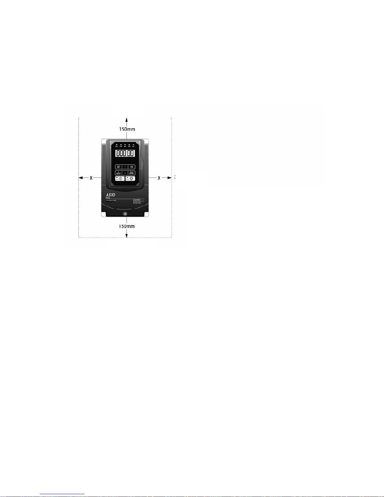
(1) Please install the A510 inverter in vertical direction, leaving enough space to
ensure the cooling effect, shown in Figure 3.1.
Avoid the upside-down or horizontal installation.
Figure 3.1 A510 Installation Space
(2) The temperature of inverter’s radiator cooling fins may reach 90 ℃ in operation.
Therefore, the contact surface for the inverter installation shall be made by the high-
temperature-resistant material.
When the inverter is operating in the power distribution box, the environment must be
ventilated and the environmental temperature must be less than +40 ° C.
Up side
Down side
Right
Left
X= for the inverter capacity of 18.5kW (including the
smaller capacity), the minimum width is recommended
as 100mm.
X= for the inverter capacity of 22 kW (including the
higher capacity), the minimum width is recommended
as 200mm.
Page 16

3-4
3.2.2 External view of the product and warning label information
External view and part name of A510 inverter:
(a) 220V 1-5HP/440V 1-7.5HP
(Wall-mounted type, IEC IP 00) (Wall-mounted type, IEC IP20, NEMA1)
Caution
The installing environment of the inverter directly affects its functions and the service
life. Therefore, the installation environment should be taken into account when installing
A510 inverter:
• Ambient temperature : -10 ℃~ +40 (NEMA 1 ℃ external installation type)
• Avoid rain, humidity or direct sunlight.
• Avoid corrosive liquid or gas, dust and metal filings
• Avoid vibration; Keep away from electromagnetic interference
• For multiple inverters installed in one plate, please equip with a fan for heat radiating
in order to make the surrounding temperature of the inverter lower than 40 . ℃
Warning Information
Warning Information
Type Specification
label
Front cove
r
Digital operato
r
Nameplate and
barcode
Nameplate
and barcode
Terminal cove
r
Fan cover
Mounting hole
Mounting hole
Fan cover
Front cove
r
Digital operato
r
Anti-dust cove
r
Heat sink
Heat sink
Type Specification
label
Terminal cover
Page 17

3-5
(b) 220V 7.5-25HP/440V 10-30HP
(Wall-mounted type, IEC IP 00) (Wall-mounted type, IEC IP20, NEMA1)
(c) 220V 30-40HP/440V 40-60HP
(Wall-mounted type, IEC IP20, NEMA1)
Front cover
Mounting hole
Mounting hole
Nameplate
and barcode
Nameplate
and barcode
Terminal cover
Digital operator
Digital operator
Front cover
Anti-dust cover
Warning Information
Warning Information
Terminal cover
Type Specification
label
Type Specification
label
Mounting hole
Front cover
Digital operator
Terminal cover
Nameplate
and barcode
Warning Information
Type Specification
label
Lifting lugs(4 pcs)
Page 18

3-6
(d) 220V 50-100HP/440V 75-215HP
(wall-mounted type,IEC IP 00) (wall-mounted type, IEC IP20, NEMA1)
Figure 3.2 External view of A510
Must be sure to read the warning information on the front cover, see Figure 3.3
Figure 3.3 Warning information label
Warning Information
Warning Information
Lifting Lugs
(4 pcs)
Nameplate
and barcode
Digital operator
Terminal cover
Type Specification
label
Terminal cove
r
Nameplate
and barcode
Lifting Lugs
(4 pcs)
Front cover
Front cove
r
Mounting hole
Mounting hole
Anti-dust cover
Type Specification
label
Wiring box
Digital operator
Page 19

3-7
3.2.3 Product Dismounting
Disassembly/assembly steps for various models of A510, as shown in following:
3.2.3.1 Standard type
(a) 220V 1-5HP/440V 1-7.5HP
Step 1: Loose screws Step 2: Disassemble external cover
Caution
For A510 wiring, it is not necessary to disassemble the digital operator. First to
loose screws of the external cover and take off the cover, then you can carry out the
wiring work to the internal terminals of the inverter.
• Models of 220V 1-25HP and 440V 1-30HP are plastic shell. It is suggested to loose
screws of the external cover and take off the cover. When wiring is completed,
assemble the external cover of terminals and fasten screws.
• Models of 220V 30HP-100HP and 440V 40~215HP are metal shell. It is suggested to
loose screws of the external cover and take off the cover. When wiring is completed,
assemble the external cover of terminals and fasten screws.
Page 20

3-8
Step 3: Wiring and assemble the cover Step 4: Fasten screws
(b) 220V 7.5-25HP/440V 10-30HP
Step 1: Loose screws Step 2: Disassemble external cover
Page 21

3-9
Step 3: Wiring and assemble the cover Step 4: Fasten screws
(c) 220V 30-40HP/440V 40-60HP
Step 1: Loose screws Step 2: Disassemble external cover
Page 22

3-10
Step 3: Wiring and assemble the cover Step 4: Fasten screws
(d) 220V 50-100HP/440V 75-215HP
Step 1: Loose screws Step 2: Disassemble external cover
Page 23

3-11
Step 3: Wiring and assemble the cover Step 4: Fasten screws
3.2.3.2 Built-in filter type (440V 1 ~60HP)
Step 1: Loose screws Step 2: Disassemble external cover
Page 24
3-12
Step 3: Loose screws of filter Step 4: Disassemble the external cover of the filter
Step 5: Wiring and assemble the filter cover, Step 6: Fasten screws
then fasten screws
Page 25

3-13
3.3 Wiring the peripheral devices of the inverter and related
cautions
Cautions
1. After the power is cut off, while the “CHARGE” indicator of the inverter is still on, it
means the discharge of the capacitor has not been completed. Don’t touch the circuit
or replace components at this time.
2. Never wire or disassemble/assemble internal connectors of inverter when the power
is supplied.
3. Prohibit connecting U,V and W of inverter output terminals to AC power.
4. Terminal E of the inverter must be well grounded.
5. Since semiconductor components are easily damaged by high voltage, do not carry
out the high voltage withstand test on internal components of A510 inverter.
6. CMOS IC of the inverter control board is easily affected and damaged by static
electricity, thus, do not touch the control board.
Cautions
1. When wiring, please refer to the table for choosing appropriate wire diameter. If the
main circuit line is too long, pay attention to the voltage drop which can not exceed 2%
of the rated voltage.
Phase voltage drop V△ =
3 ×wire resistance (Ω/km)×wiring distance (m)×current
(A)×10-3
2. In case of a long wire between the inverter and the motor, please reduce the carrier
frequency appropriately (parameters 11-01).
Cautions
To ensure the security of the interface device, it is recommended that a fast-acting fuse
be added at the input side of the inverter, especially for high-power systems. The
specification of applied fast-acting fuse can be referred to Section 6.6.
Page 26
3-14
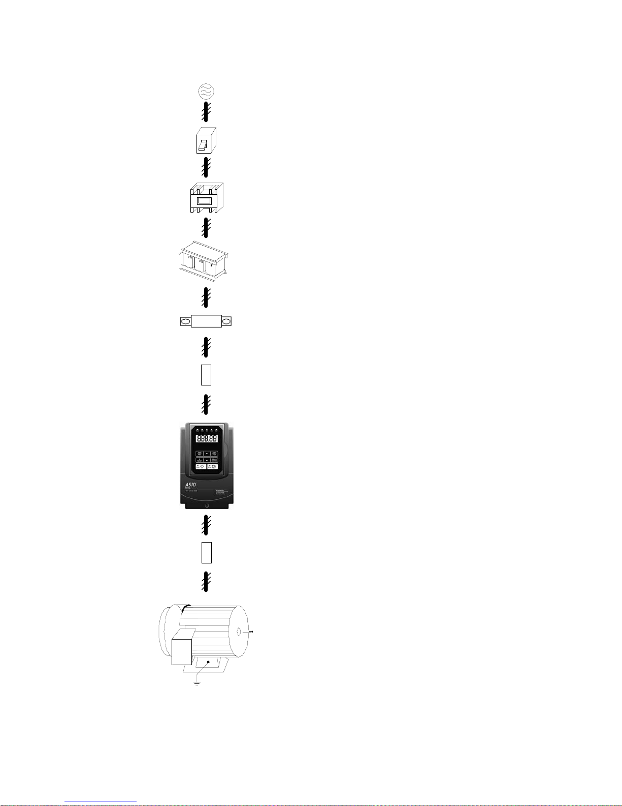
Examples for wiring the periphery devices of A510 are shown in the following:
電源
無熔絲開關 NFB
(及漏電斷路器)
電磁接觸器
AC 電抗器
輸入側雜訊
濾波器
變頻器
零相雜訊濾波器
三相感應
馬達
外加高速保險絲
■ No fuse breaker (NFB) and Leakage Circuit
Breaker
‧ Please refer to table 3 for choosing NFB of
appropriate current.
‧ Do not use NFB to control the start/stop of the
inverter.
‧ If a leakage circuit breaker is added for leakage
protection, its current sensitivity shall be more
than 200mA and action time more than 0.1 (VTYPE), so as to avoid high-frequency
malfunction.
■ Electromagnetic contactor
‧ It can not add the electromagnetic contactor for
general use. However, for the application
requiring external sequence control or
automatic restart function after power cut, an
electromagnetic contactor is required.
‧ Please avoid using electromagnetic contactor
for the start/stop control of the inverter as
possible.
■ AC reactor
‧ In case of further improving the power factor or
suppress the external surge, an AC reactor can
be additionally equipped.
■ Fast acting fuse
‧ To protect interface devices, it is necessary to
add a fast acting fuse (fuse specification will be
referred to Section 6.6)
■ Input Noise filter
‧ A510 is matched with TECO special filter,
meeting the EN 55011 class A criterion.
‧ The selection of input noise filter can be
referred to Section 6.4)
■ Inverter
‧ Terminal R,S,T at input side have no phase
sequence requirement, thus they can be
arbitrarily exchanged.
‧ Terminal E must be well grounded.
Power supply
No Fuse Breaker
(NFB) and Leakage
Circuit Breaker
Electromagnetic
contactor
AC reactor
Fast acting fuse
Input Noise filter
Inverter
Zero-phase
noise filter
3-phase
induction
motor
Page 27

3-15
■ Zero-phase noise filter
‧ Adding a zero-phase noise filter at the output
side of the inverter can decrease the radiated
interference and induced noise.
‧ Please refer to Section 6.5
■ Motor
‧ If an inverter drives multiple motors, the rated
current of the inverter must be greater than the
total current that all motors operate at the same
time.
‧ Motor and inverter must be grounded
respectively.
Page 28

3-16
■ Wiring
The following is the standard wiring diagram for the A510 inverter ( indicates ◎ main
circuit terminal ,○ indicates control circuit terminal ). Locations and symbols of the wiring
terminal block might be different due to different models of A510. The description of main
circuit terminal and control circuit terminal can be referred to table 1 and 2.
3.4 Functional description of terminals
MCNFB
B1/P B2
煞車電阻
R/L1
S/L2
S1
S2
S8
S7
S6
S5
S4
S3
類比輸出1
多
機
能
接
點
輸
入
24V
數位信號電源端子
24VG
數位信號共同端子
故障重置
正向運轉/停止
多段速指令1
寸動指令
外部Base block
Source(PNP)
SW3
AO1
AO2
GND
E
CN3
類比輸出2
E
T/L3
U/T1
V/T2
W/T3
CN6 (RJ45)
1
2
脈波指令輸入
遮蔽線連接端子
GND 類比信號共同端子
E
+12V
類比輸入用電源
AI1 多機能類比輸入
(-10~10V/0~10V, 20K
AI2 多機能類比輸入
P
P
DO2
DOG
S(+)
S(-)
PI
PO
-12V 類比輸入用電源
P
P
IM
R2C
R1A
R1B
R1C
R2A
F1
F2
安全輸入接點
+12V, 20mA
(-10~10V/0~10V/4~20mA, 250
32K Hz. Max.
I , 出廠設定
SW2
主迴路電源
出
廠
設
定
外
部
類
比
輸
入
-10V~0~10V
4~20mA/0~10V
0V
Sink(NPN), 出廠設定
脈波輸入
反向運轉/停止
UP/增頻率命令
DOWN/減頻率命令
第三種接地
電阻值100
以下
類比信號輸出1, 2
(DC 0~10V)
選購擴充卡(PG卡)
多機能繼電器輸出
250VAC, 1A以下
30VDC, 1A以下
多機能光耦輸出
(DC 48V/50mA, Open Collector)
多機能脈波輸出
32k Hz. Max.
GND
RS485通訊埠
DO1
表隔離線,
表雙絞芯隔離絞線
P
端子符號 表示主迴路,
表示
控制迴路
*2
*1
*3
*5
*6
*5
*1:僅220V 1~25HP與440V 1~30HP(含)以下容量內建剎晶體機種主回路提供B2端子,可直接於B1, B2間連接煞車電阻。
備註說明:
*2:多機能數位輸入接點S1~S8,可透過開關SW3設置成Source(PNP)或Sink(NPN)模式。
*3:多機能類比輸入2(AI2),可透過開關SW3設置成電壓命令輸入(0~10V/-10~10V)或電流命令輸入(4~20mA)。
*4
*4:安全輸入接點F1, F2間需短接變頻器始可正常輸出,使用安全輸入時,請務必拆下F1-F2間的短接線。
*5:僅220V 3HP與440V 5HP(含)以上機種,提供-12V, R2A-R2C與PO-GND端子。
*6:僅220V 2HP與440V 3HP(含)以下機種,提供DO2端子。
*5
Braking resistor
F
ast acting fuse
Main circuit power
Default setting
Forward rotation/stop
Reversal rotation/stop
Up command
Down command
Multi-step speed
command 1
Fault reset
Jog command
External base block
Multi-function input
Default setting
Analog output 1
Analog output 2
The third type grounding.
Resistance lower than 100
ohm.
Analog signal output 1, 2
Option Card (PG)
Multi-function relay output
Power terminal of digital signal
250VAC, under 1A
30VDC, under 1A
Multi-function pulse output
RS485 Communication port
Multi-function photocoupler output
AI1 Multi-function analog input
(-10~10V/0~10V, 20KΩ)
AI2 Multi-function analog input
(-10~10V/0~10V/4~20mA, 250Ω)
Default
setting
Safety input contact
GND Mutual terminal of analog signal
-12V Power of analog input
+12V Power of analog input, +12v,20mA
PI Pulse command input 32K Hz. Max.
Pulse input
E
x
t
erna
l
ana
l
og
i
npu
t
Connection terminal of shielding wire
24VG Mutual terminal of digital signal
Means Isolated twisted twire
Means
isolated
wire
Terminal symbol ◎ indicates main circuit,
○ indicates control circuit
Remark:
*1: Only the master circuit of 220V1~25HP and 440 V1~30HP (included) or models of lower capacity with built-in braking resistor provide terminal B2.
The braking resistor can be connected directly between B1 and B2.
*2: The multi-function digital input terminals S1~S8 can be set to Source (PNP) or Sink (NPN) mode through the SW3.
*3: Multi-function analog input 2 (AI2) can be set to the voltage command input (0-10/-10-10v) or the current command input (4~20mA) through the
SW3.
*4: Safety input connector F1 and F2 should be shorted so that the inverter outputs properly. When the safety input is used, please be sure to remove
the short-pin between F1 and F2.
*5: Only 220 V 3HP and 440 v 5HP (included) or models above, provide terminals -12V, R2A-R2C and PO-GND.
*6. Only 220 V 2HP and 440 v 3HP (included) or models below, provide terminal DO2.
Page 29

3-17
3.4 Terminal Description
Table 1 Major Circuit Terminals
Terminal
mark
220V: 1~25HP
440V: 1~30HP
220V: 30~100HP
440V: 40~215HP
R/L1
S/L2
T/L3
Power supply of the main terminal ( single phase, only
connect R-S)
B1/P
B2
-
\
• B1/P-\: DC power
supply
• B1/P-B2: externally
connected braking resistor
⊕
-
• ⊕ -\: DC power
supply or
connect braking
detection
module
U/T1
V/T2
W/T3
Inverter output
E
Grounding terminal (the third type grounding)
■ Main Circuit Terminal Layouts
˙220V : 1 ~ 2HP , 440V : 1 ~ 3HP
R/L1 S/L2 T/L3
B1/P
U/T1 V/T2
W
/
T3B2
˙220V : 3 ~ 5HP , 440V : 5 ~ 7.5HP
R
/L1
S
/L2
T
/L3
B1/P B2
U
/T1V/T2
Power In
Dynamic Brake
To Motor
W
/T3
CHARGE
˙220V : 7.5~10HP , 440V : 10 ~ 15HP
R
/L1S/L2T/L3
E
B1/P
B2
Power In
Dynamic Brake
CHARGE
U
/T1V/T2W/T3
E
To Moto
r
B1/R
Page 30

3-18
˙220V : 15~25HP , 440V : 20 ~ 30HP
R/L1 S/L2 T/L3 U/T1 V/T2
W
/
T3B1/P B2
˙220V : 30 ~40HP , 440V : 40 ~ 60HP
R/L1 S/L2 T/L3 U/T1 V/T2
W
/
T3
˙220V : 50~60HP, 440V : 75~100HP
˙220V : 75~100HP, 440V : 125~215HP
Page 31

3-19
Table 2 Main circuit terminals
Type Terminal terminal function Signal level
S1
Forward rotation─ stop command
(default), multi-function input terminals * 1
S2
Reversal rotation- stop command
(default), multi-function input terminals * 1
S3
UP increases command(default), multifunction input terminals * 1
S4
DOWN reduces command(default), multifunction input terminals * 1
S5
Multi-step speed frequency command 1,
multi-function input terminal* 1
S6
fault reset input, multi-function input
terminal * 1
S7
JOG frequency command, multi-function
input terminal * 1
Digital
input
signal
S8
External B.B.(Base Block) input, multifunction input terminal * 1
24 VDC, 8 mA optocoupler isolation
(maximum voltage of 30
Vdc, input impedance of
9.03kΩ optocoupler)
24V
Digital signal SOURCE sharing point
(SW3 switched to SOURCE )
24V
Power
supply
24VG
Common terminal of Digital signals
Common point of digital signal SINK
( SW3 switched to SINK )
±15%,
Maximum output
current: 250mA( the sum
of all load )
+12V Power for speed setting
+12V
( Maximum current ,
20mA)
-12V
Only above 220V 3HP/ 440V 5HP
(include) support this terminal function
-12V
(Maximum current, 20mA)
AI1
Voltage mastering speed command (010V input)/(-10V~10V input)
From 0 to +10V,
From -10V to +10V
(Input impedance : 20KΩ)
(11bit + 1 symbol,
resolution)
AI2
Multi-function analog input terminals *2,
can use SW2 to switch voltage or current
input (0~10V)/(4-20mA)
From 0 to +10V,
From -10V to +10V
(Input impedance: 20KΩ)
From 4 to 20 mA
(Input impedance:
250KΩ)
(11bit + 1 symbol,
resolution)
GND Analog signals sharing terminal ----
Analog
input
signal
E
Shielding wire’s connecting terminal
(Ground)
----
Page 32

3-20
Type Terminal terminal function Signal level
AO1
Multi-function analog output terminals *3
(0~10V output)
AO2
Multi-function analog output terminals *3
(0~10V output)
Analog
output
signal
GND Analog signals sharing terminal
From 0 to 10V,
( Maximum current,
20mA )
(PWM 10KHz
resolution )
PO
Pulse output, BW 32KHz, only above
220V 3HP/ 440V 5HP (include) support
this terminal function.
32KHz(max), +12V
output
(load: 2.2kΩ)
Pulse
output
signal
GND Analog signals sharing terminal ----
PI
Pulse command input, frequency width
of 32KHz
L: from 0.0 to 0.5V
H: from 4.0 to 13.2V
0 - 32 KHz(max)
(impedance:3.89 KΩ)
Pulse
input
signal
GND Analog signals sharing terminal ----
DO1
DO2
(F1 only)
Multi-function(open collector resistor)
output: in operation, zero speed,
frequency consistency, consistency at
any frequency, output frequency ,
preparation completion, low-voltage
detection, output breaker, rotation and
frequency command, over-torque
detection, abnormal, low-voltage,
Overheat, motor overload, inverter
overload, retrying, communication error,
timing functional output device……
48Vdc, 2~50mA
Opto-coupling output
Digital
output
DOG
Sharing terminal of the open collector
transistor
R1A
R1B
R1C
Relay A contact (multi-function output
terminal)
Relay B contact (multi-function output
terminal)
Relay common terminal,
With the same function as DO1/DO2
Terminal capacity:
at 250Vac, 10 mA~1A
at 30Vdc, 10 mA~1A
Relay
output
R2A-R2C
(above
F2)
With the same function as DO1/DO2
Terminal capacity:
at 250Vac, 10 mA~1A
at 30Vdc, 10 mA~1A
F1
on: free rotation with safe input
off: general rotation
(if use external safety switch to stop, you
must remove the short circuit pin.)
24Vdc, 8mA, pull-high
safety
input
F2 Safety command common terminal 24V Ground
S (+)
RS-485
port
S (-)
RS485/MODBUS
Opto-coupler isolation,
differential input and
output
Grounding
E (G)
Grounding to earth
Shield the connecting terminal
----
Page 33

3-21
*1:Multi-function digital input can be referred to the manual.
*2:Multi-function analog input can be referred to the manual.
*3:Multi-function analog output can be referred to the manual.
Caution
‧ Maximum output current capacity of the terminal 12V is 20mA.
‧ Multi-function analog output AO1 and AO2 are special for the analog output of meter.
Please don’t use them to the analog signal output of feedback control.
‧ Control board’s 24V & ±12V just been used for internal control, please don’t connect
to external other devices to use.
Page 34

3-22
3.5 Internal wiring diagram of main circuit
Various models of A510’s internal wiring diagram of main circuit are shown as the
following:
1. 220V:1HP 440V: 1~2HP
2. 220V: 2~25HP 440V: 3~30HP
3. 220V: 30~40HP 440V: 40~60HP
4. 220V: 50~60HP 440V: 75~100HP
5. 220V: 75HP, 100HP 6. 440V: 125HP, 150HP, 175HP, 215HP
E
U(T1)
W(T3)
V (T2)
S
(L2)
T(L3)
E
○─
CONTROL
CIRCUITS
R/L1
S/L2
T/L3
U/T1
V/T2
W
/T3
B1/P
SPS
B2
E
○
─
CONTROL
CIRCUITS
R/L1
S/L2
T/L3
U/T1
V/T2
W
/T3
B1/P
SPS
B2
E
○
─
CONTROL
CIRCUITS
R/L1
S/L2
T/L3
U/T1
V/T2
W
/T3
SPS
○┼
N
P
DCL
C/B
SPS
R(L1)
E
N
P
DCL
SPS
C/B
AC/DC
W(T3)
R(L1)
T(L3)
S
(L2)
U(T1)
V(T2)
E
N
P
DCL
SPS
C/B
AC/DC
R(L1)
S(L2)
T(L3)
U(T1)
V (T2)
W(T3)
Page 35

3-23
3.6 Instrument for main circuit wiring and caution
■ Instrument for main circuit wiring
Whether the MC should be installed or not is depended on the actual requirement,
while the NFB must be installed between the AC supply and power input ports R, S, T of
A510. If a leakage breaker is additionally added for protection to avoid the malfunction of
leakage breaker, its current sensitivity shall be over 200mA, and acting time over 0.1
seconds.
Table 3 Wiring instrument for 220V/440V class
A510 Model wire diameter (mm2)
Power
horse
power
(HP)
*1
Rated
KVA
Rated
current
(A)
HD/ND
Main
circuit
*2
Grounding
line
E(G)
Control
line
*3
NFB
*4
MC*4
1HP 1.9 5/6
2~5.5 2~5.5 0.5~2
TO-50EC(15A) CU-11
2HP 3 8/9.6
2~5.5 3.5~5.5 0.5~2
TO-50EC(20A) CU-11
220V
1 Ø/3Ø
3HP 4.2 11/12
3.5~5.5 3.5~5.5 0.5~2
TO-50EC(30A) CU-11
5.4HP 6.7 17.5/21 5.5 5.5
0.5~2
TO-50EC(30A) CU-16
7.5HP 9.5 25/30 8
5.5~8 0.5~2
TO-100S(50A) CU-18
10HP 12.6 33/40 8
5.5~8 0.5~2
TO-100S(50A) CU-25
15HP 17.9 47/56 14 8
0.5~2
TO-100S(100A) CU-50
20HP 22.9 60/69 22 8
0.5~2
TO-100S(100A) CU-65
25HP 28.6 73/79 22 14
0.5~2
TO-225S(100A) CU-80
30HP 32.4 85/110 38 14
0.5~2
TO-225S(150A) CN-100
40HP 43.8 115/138 60 22
0.5~2
TO-225S(175A) CN-125
50HP 55.3 145/169 80 22
0.5~2
TO-225S(200A) CN-150
60HP 68.6 180/200 100 22
0.5~2
TO-225S(225A) CN-180
75HP 81.9 215/250 150 22
0.5~2
TO-400S(300A) CN-300
100HP 108 283/312 200 38
0.5~2
TO-400S(400A) CN-300
125HP 132 346/360
220V
3 Ø
150HP 158 415/450
1HP 2.6 3.4/4.1
2~5.5 2~5.5 0.5~2
TO-50EC(15A) CU-11
2HP 3.2 4.2/5.4
2~5.5 3.5~5.5 0.5~2
TO-50EC(15A) CU-11
3HP 4.2 5.5/6.9
2~5.5 3.5~5.5 0.5~2
TO-50EC(15A) CU-11
5.4HP 7 9.2/11.1
2~5.5 3.5~5.5 0.5~2
TO-50EC(15A) CU-18
7.5HP 11.3 14.8/17.5
3~5.5 3.5~5.5 0.5~2
TO-50EC(20A) CU-18
10HP 13.7 18/23 5.5 5.5
0.5~2
TO-50EC(30A) CU-25
15HP 18.3 24/31 8 8
0.5~2
TO-100S(50A) CU-25
20HP 23.6 31/38 8 8
0.5~2
TO-100S(50A) CU-35
25HP 29.7 39/44 8 8
0.5~2
TO-100S(50A) CU-50
30HP 34.3 45/58 14 8
0.5~2
TO-100S(75A) CU-50
40HP 45.7 60/72 22 8
0.5~2
TO-100S(100A) CU-65
50HP 57.2 75/88 22 14
0.5~2
TO-100S(100A) CU-80
60HP 69.3 91/103 38 14
0.5~2
TO-225S(150A) CN-100
75HP 85.4 118/145 60 22
0.5~2
TO-225S(175A) CN-125
100HP 114 150/165 80 22
0.5~2
TO-225S(225A) CN-150
125HP 137 180/208 150 22
0.5~2
TO-400S(300A) CN-300
150HP 165 216/250 150 22
0.5~2
TO-400S(300A) CN-300
440V
3 Ø
175HP 198 260/296 200 30
0.5~2
TO-400S(400A) CN-300
Page 36

3-24
A510 Model wire diameter (mm
2
)
Power
horse
power
(HP)
*1
Rated
KVA
Rated
current
(A)
HD/ND
Main
circuit
*2
Grounding
line
E(G)
Control
line
*3
NFB
*4
MC*4
215HP 225 295/328 250 30
0.5~2
TO-400S(400A) CN-300
250HP 270 352/380
300HP 317 415/470
375HP 400 523/585
*1: Fixed torque load shall prevail.
*2: The main circuit contains R/L1, S/L2, T/L3 , U/T1, V/T2, W/T3, B1/P, B2, \, ♁。
*3: Control line is the terminal wire on the control board.
*4: The NFB and MCB listed in the table are of TECO product numbers, products with
same rated specification of other brands are available. To reduce electrical noise
interference, please ensure that R-C surge absorbe
r (R: 10Ω/5W, C: 0.1μf/1000VDC)
are added at both sides of MCB coil.
*5: 220V 125HP/ 440V 250HP or above is being developed.
Page 37

3-25
For the external wiring, please attention to the followings:
(A) Control Circuit wiring:
(1) Control circuit wiring (control terminal) must be isolated from main circuit wiring (R,
S, T, U, V, W) and other power lines, so as to avoid electrical noise interference.
(2) Contact output terminal R1A, R1B, R1C (or R2A, R2C) must be isolated from
terminal c~j, A01, A02, GND, DO1, DO2, DOG, +12V-, -12V, AI1, AI2, GND
when wiring.
(3) In order to avoid the electrical noise interference, the control circuit wiring must
adopt shielding isolation twisted wire, please refer to the following diagram; the
wiring distance should not exceed 50m.
接至變頻器控制端子E
遮蔽隔離線
護套
此端遮蔽線
不連接
以絕緣膠帶包覆
Figure 3 Isolation twisted wire treatment
When connecting the output contact of the multi-function optocoupler to the relay, it is
necessary to add flywheel diode in parallel to both sides of the relay coil, as shown in the
following diagram.
Figure 4 Optical coupler output contacts connected inductive load
g
飛輪二極體
Flywheel diode
(above 100V 100mA)
48V max.
g
50 mA max.
A
510
外部配線回路
External wiring circuit
Connected to the control terminal E of
inverter
Protective covering
Shielding isolation wire
Do not connect the shielding isolation wire at
this side
Wrapped with insulating tape
Page 38

3-26
(B) Main Circuit wiring :
(1) It doesn’t need to consider the phase sequence for input power R, S, T.
(2) Prohibit connecting U,V and W of inverter output terminals to AC power.
(3) Inverter output terminal U, V and W are connected to the motor terminal U, V, W. If
the inverter executes forward rotation instruction while the motor rotates in reversal
direction, simply exchange any two wires of U, V, W is enough.
(4) Never connect the inverter output terminal to the capacitor or LC,RC noise filter of
improving the power factor.
(C) Grounding wire :
(1) Grounding terminal (E) is grounded to the earth by the third type grounding way.
(grounding resistance of 100Ω or less)
(2) Inverter grounding wire can not be grounded together with high-current loads such
as welding machines and high-powered motors and so on. They must be grounded
respectively.
(3) Grounding wire size follows the specification of electrical equipment technical
basis. The shorter grounding wire is, the better it is.
(4) If several inverters are grounded jointly, please refer to the following diagrams for
grounding. Do not form a circuit in grounding.
(a) 良 (b) 良 (c) 不良
Figure 5 Grounding ways of several A150 jointly
(a) Good
(b) Good (c) Not Good
Page 39

3-27
◎ Determine wire size
When choosing wire, a consideration of the voltage drop caused by the wire is a
must.
Voltage drop is calculated as shown below. In general, the voltage drop shall be
controlled below 2% of the rated voltage. Voltage drop between wires (V) = × wire
resistance (Ω / km) × wiring length (m) × current (A) × 10-3
◎ AC reactor for parallel power coordination
If the capacity exceeds 600kVA, please add AC reactor to the input side of the
inverter in series. AC power can be used for power coordination and power factor
improvement.
◎ Wiring length between the inverter and the motor
If the total length between the inverter and the motor, the inverter itself and other
peripheral devices will be affected because the high-frequency carrier frequency (ie,
the IGBT ON / OFF switching frequency) of the inverter will increase the leakage
current between wiring and the ground. As a result, if the wiring length between the
inverter and the motor is very long, please modestly reduce the carrier frequency, as
shown below.
Wiring distance between
the inverter and the
motor
<30m 30m ~ 50m
50m
~100m
100m≧
Allowable carrier
frequency
(set values of 11-01 )
16kHz(max) 10kHz(max) 5kHz(max) 2kHz(max)
Page 40

3-28
3.7 Inverter Specifications
Basic Specifications
(a) 220V class
Inverter capacity (HP)
1 2 3 5 7.5 10 15 20 25 30 40 50 60 75 100 125 150
Rated output Capacity (KVA)
1.9 3 4.2 6.7 9.5 12.6 17.9 22.9 28.6 32.4 43.8 55.3 68.6 81.9 108 132 158
Rated output
current (A)
5 8 11 17.5 25 33 47 60 73 85 115 145 180 215 283 346 415
Heavy-load
type
H.D.(150%/1
min)
Maximum
applicable
motor
*1
HP
(KW)
1
(0.75) 2 (1.5) 3 (2.2) 5 (3.7)
7.5
(5.5)10(7.5)15(11)
20
(15)
25
(18.5)
30
(22)
40
(30)
50
(37)
60
(45)
75
(55)
100
(75)
125
(90)
150
(110)
Rated output
current (A)
6 9.6 12 21 30 40 56 69 79 110 138 169 200 250 312 360 450
Standardload type
N.D.(120%/1
min)
Maximum
applicable
motor
*1
HP
(KW)
1.5
(1.1) 3 (2.2) 4 (3)
7.5
(5.5)
10
(7.5)
15
(11)
20
(15)
25
(18.5)
30
(22)
40
(30)
50
(37)
60
(45)
75
(55)
100
(75)
125
(90)
150
(110)
175
(130)
The maximum output voltage
(V)
3-phase, 200V~240V
Output rated
The maximum output
frequency (Hz)
Based on parameter setting 0.1~400.0(1200.0) Hz
Rated voltage, frequency
Single/3-phase
200V~240V,
50/60Hz
3-phase 200V~240V, 50/60Hz
Allowable voltage fluctuation -15% ~ +10%
Power
Allowable frequency
fluctuation
±5%
(b) 440V class
Inverter capacity (HP)
1 2 3 5 7.5 10 15 20 25 30 40 50 60 75 100 125 150 175 215
Rated output Capacity (KVA)
2.6 3.2 4.2 7 11.3 13.7 18.3 23.6 29.7 34.3 45.7 57.2 69.3 85.4 114 137 165 198 225
Rated output
current (A)
3.4 4.2 5.5 9.2 14.8 18 24 31 39 45 60 75 91 118 150 180 216 260 295
Heavy-load
type
H.D.(150%/
1min)
Maximum
applicable motor
*1
HP (KW)
1
(0.75
)
2
(1.5
)
3
(2.2
)
5
(4)
7.5
(5.5)
10
(7.5)
15
(11)
20
(15)
25
(18.
5)
30
(22)
40
(30)
50
(37)
60
(45)
75
(55)
100
(75)
125
(90)
150
(110)
175
(132)
215
(160)
Rated output
current (A)
4.1 5.4 6.9 11.1 17.5 23 31 38 44 58 72 88 103 145 165 208 250 296 328
Standardload type
N.D.(120%/
1min)
Maximum
applicable motor
*1
HP (KW)
2
(1.5)
3
(2.2
)
4
(3)
7.5
(5.5)
10
(7.5)
15
(11)
20
(15)
25
(18.5
)
30
(22)
40
(30)
50
(37)
60
(45)
75
(55)
100
(75)
125
(90)
150
(110)
175
(132)
215
(160)
250
(185)
The maximum output voltage
(V)
3-phase 380V~480V
Output rated
The maximum output
frequency (Hz)
Based on parameter setting 0.1~400.0(1200.0) Hz
Rated voltage, frequency 3-phase 380V ~ 480V, 50/60Hz
Allowable voltage fluctuation -15% ~ +10%
Power
Allowable frequency
fluctuation
±5%
Page 41

3-29
Inverter capacity (HP) 250 300 375
Rated Output capacity (KVA) 270 317 400
Rated output
current (A)
370 450 523
Heavy-load
type
H.D.(150%/
1min)
Maximum
applicable motor
*1
HP (KW)
250
(185)
300
(220)
375
(280)
Rated output
current (A)
435
15 600 Standardload type
N.D.(120%/
1min)
Maximum
applicable motor
*1
HP (KW)
270
(200)
335
(250)
425
(315)
The maximum output voltage
(V)
3-phase 380V~480V
rated Output
The maximum output
frequency (Hz)
Based on parameter
setting 0.1~400.0
Hz
Rated voltage, frequency
3-phase 380V ~
480V, 50/60Hz
Allowable voltage fluctuation -15% ~ +10%
Powe
r
Allowable frequency
fluctuation
±5%
* 1 Take standard 4-pole induction motor as the base.
* 2 HD (heavy load type): 150% / 1 min, 200% / 2sec, carrier range: 2KHZ ~ 16KHZ , the factory
setting is 8KHZ (220V ~ 20HP / 440V ~ 30HP).
* 3 HD (heavy load type): 150% / 1 min, 200% / 2sec, carrier range: 2KHZ ~ 12KHZ, the factory
setting is 5KHZ (440V 40 ~ 50HP).
* 4 HD (heavy load type): 150% / 1 min, 200% / 2sec, carrier range: 2KHZ ~ 12KHZ, the factory
setting is 6KHZ (220V 25HP).
* 5 HD (heavy load type): 150% / 1 min, 200% / 2sec, carrier range: 2KHZ ~ 12KHZ, the factory
setting is 5KHZ (220V 30 ~ 40HP).
* 6 HD (heavy load type): 150% / 1 min, 200% / 2sec, carrier range: 2KHZ ~ 10KHZ , the factory
setting is 5KHZ (220V 50 ~ 100HP/440V 60 ~ 175HP).
* 7 HD (heavy load type): 150% / 1 min, 200% / 2sec carrier range: 2KHZ ~ 8KHZ, the factory setting
is 3KHZ (440V 215HP).
* 8 ND (standard load type): 120% / 1 min, carrier range: 2KHZ ~ 16KHZ, the factory setting is 2KHZ.
* 9 A510 model is designed to use in heavy load conditions, the factory setting takes HD (heavy load
type) as the base.
* 10 if it is greater than factory carrier frequency, you need to adjust the load current based on the de-
rating curve.
* 11. 220V 125HP / 440V 250HP models or above are being developed.
Page 42

3-30
The following shows maximum frequencies under different control modes.
Load
mode
Control
mode
Other settings
Maximum
frequency
maximum frequency set to
400Hz (00-31 = 0)
400Hz
V/F
V/F + PG
maximum frequency set to
1200Hz (00-31 = 1)
1200Hz
220V 1~10HP, 440V
1~15HP
150Hz
220V 15~25HP, 440V
20~30HP
110Hz
SLV
220V 30~100HP, 440V
40~375HP
100Hz
SV unlimited 400Hz
Heavy
load
(00-27=0)
PMSV unlimited 400Hz
maximum frequency set to
400Hz (00-31 = 0)
120Hz Slight
load
(00-27=1)
V/F
V/F + PG
maximum frequency set
to1200Hz (00-31 = 1)
1200Hz
Page 43

3-31
General Specifications
Operation mode Seven-segment display * 5 + LED keypad (it is allowable to buy LCD keypad with parameter copy function)
Control mode V/F, V/F+PG, SLV, SV, PMSV, PMSLV with space vector PWM mode
Frequency control range 0.1Hz~400.0Hz(1200.0Hz)
Frequency accuracy
(Temperature change)
Digital references: ±0.01%(-10 ~ +40 )℃ , Analog references: ±0.1% (25 ±10)℃℃
Speed control accuracy ±0.1%( vector control(SV)),±0.5%( vector control without sensor)
Frequency setting
resolution
Digital references:0.01Hz , Analog references: 0.06Hz/60Hz
Output frequency
resolution
0.01Hz
Overload Tolerance
rated output current 150%/1 min, 200%/2sec(H.D mode),120%/1 min (N.D mode), factory setting of 150%/1 min,
200%/2sec
frequency setting signal DC 0 ~ +10V / 4 ~ 20mA or DC-10V~+10V and pulse –type command frequency
Acceleration / deceleration
time
0.0~6000.0 second (separately set acceleration and deceleration time )
Voltage, frequency
characteristics
Can arbitrarily set V / f curve based on parameters
Braking torque About 20%
Main control functions
Auto tuning, Zero Servo, torque control, position control, Droop, Soft-PWM, over-voltage protection, dynamic braking,
speed search, frequency traversing, instantaneous power fault restart, PID control, automatic torque compensation, slide
difference compensation, RS-485 communication standard, speed feedback control, simple PLC function, 2 sets of analog
output, safety switch.
Control characteristics
Other functions
Accumulated record of power supply time and operation time, 4 sets of fault history record and the latest fault record
state, energy-saving function setting, single phasing protection, smart braking,DC braking, Dwell, S curve acceleration and
deceleration, Up / Down operation, MODBUS communication type, output of pulse multiple, display of any engineering
unit, Local / Remote switching keys, SINK / SOURCE input interface option
Stall protection
Action current can be set (in acceleration or constant speed, it can be set separately. In deceleration, it can be set with /
without)
Instantaneous over current
(OC) and output shortcircuit (SC) protection
It stops when the current exceeds 200% of the inverter rated current.
Inverter overload
Protection (OL2)
inverter rated current is 150%/1 min., in case of 200%/2sec, it stops (H.D type),carrier of the factory setting is 8~2KHZ.
In case of 120%/1 min, it stops(N.D. type), carrier of the factory setting is 2KHZ。
Motor overload (OL1)
protection
Electrical overload protection curve
Over voltage(OV)
protection
If the main circuit DC voltage is over 410V (220V class) / 820V (440V class), the motor stops running.
Under voltage (UV) If the main circuit DC voltage is under 190V (220V class) / 380V (440V class), the motor stops running.
Automatic restart after
instantaneous power fault
Power fault exceeds 15ms
You can set the function of automatic restart after instantaneous power fault in 2sec
Overheat protection(OH) Use temperature detector for protection
Ground Fault
protection(GF)
Use current detector for protection
Protection in charge state When main circuit DC voltage 50V≧ , the CHARGE LED is on.
Protection functions
Output Phase Loss
Protection (OPL)
If the OPL function acts, the motor stops rotation automatically.
Location
Indoor (protected from corrosive gases and dust)
Ambient temperature
-10~+40 without de℃ -rating (IP20/NEMA1), -10~+50 (IP00), with de℃ -rating, its maximum operation temperature is
60℃
Storage temperature -20~+70℃
Humidity 95%RH or less ( no condensation )
Environment
Specification
Altitude and vibration altitude of 1000 meters or lower, below.5.9m/s2(0.6G)
Communication function RS-485 standard with built-in (MODBUS) (RJ45)
PLC function Built-in
EMI protection The added noise filter is in line with EN61800-3 , 400V 215HP or below can be built in.
EMS protection Follows EN61800-3
Option open pole/wire drive/PM encoder feedback card
Page 44

3-32
Derating curve based on the carrier
(a) 220Vmodel
220V 25HP
ND
HD
HD of
80%
0 2KHz 6KHz 12KHz
220V ~20HP
ND
HD
HD of
80%
0 2KHz 8KHz 16KHz
(Fc)
220V 30~40HP
ND
HD
HD of
80%
0 2KHz 5KHz 12KHz
(Fc)
(Iout)
(Iout)
(Iout)
(Fc)
Page 45

3-33
(b) 440V model
440V ~30HP
ND
HD
HD of
60%
0 2KHz 8KHz 16KHz
(Fc)
220V 50~100HP
ND
HD
HD of
80%
0 2KHz 5KHz 10KHz
(Iout)
(Fc)
440V 40~50HP
ND
HD
HD of
80%
0 2KHz 5KHz 12KHz
(Iout)
(Iout)
(Fc)
Page 46

3-34
440V 215~250HP
ND
HD
HD of
70%
0 2KHz 3KHz 8KHz
440V 60~175HP
ND
HD
HD of
70%
0 2KHz 5KHz 10KHz
ND
HD
80% of HD
0 2KHz 5KHz
220V 125~150HP
440V 300~375HP
(Iout)
(Fc)
(Iout)
(Iout)
(Fc)
(Fc)
Page 47

3-35
Set the descending rated curve based on temperature
.
ND
HD
60% of ND
60% of HD
0 40 ℃ 60 ℃
Rated current
Temperature
Page 48

3-36
3.8 Overall Dimension drawing
3.8.1 Standard Model
(a) 220V :1-5HP/440V :1-7.5HP
Dimension (mm)
Inverter Model
W H D W1 H1 t d GW(kg) Reactor
A510-2001-H 130 215 150 118 203 5 M5 2.2
A510-2002-H 130 215 150 118 203 5 M5 2.2
A510-2003-H 140 279 177 122 267 7 M5 3.8
A510-2005-H3 140 279 177 122 267 7 M5 3.8
A510-4001-H3 130 215 150 118 203 5 M5 2.2
A510-4002-H3 130 215 150 118 203 5 M5 2.2
A510-4003-H3 130 215 150 118 203 5 M5 2.2
A510-4005-H3 140 279 177 122 267 7 M5 3.8
A510-4008-H3 140 279 177 122 267 7 M5 3.8
with option
DCL
(b) 220V :7.5-25HP/440V :10-30HP
Page 49

3-37
Dimension (mm)
Inverter Model
W H D W1 H1 t d GW(kg) Reactor
A510-2008-H3 210 300 215 192 286 1.6 M6 6.2
A510-2010-H3 210 300 215 192 286 1.6 M6 6.2
A510-2015-H3 265 360 225 245 340 1.6 M6 10
A510-2020-H3 265 360 225 245 340 1.6 M6 10
A510-2025-H3 265 360 225 245 340 1.6 M6 10
A510-4010-H3 210 300 215 192 286 1.6 M6 6.2
A510-4015-H3 210 300 215 192 286 1.6 M6 6.2
A510-4020-H3 265 360 225 245 340 1.6 M6 10
A510-4025-H3 265 360 225 245 340 1.6 M6 10
A510-4030-H3 265 360 225 245 340 1.6 M6 10
with option
ACL
(c) 220V :30-40HP/440V :40-60HP
Dimension (mm)
Inverter Model
W H D W1 H1 t d GW(kg) Reactor
A510-2030-H3 284 525 252 220 505 1.6 M8 30
A510-2040-H3 284 525 252 220 505 1.6 M8 30
A510-4040-H3 284 525 252 220 505 1.6 M8 30
A510-4050-H3 284 525 252 220 505 1.6 M8 30
A510-4060-H3 284 525 252 220 505 1.6 M8 30
with option
ACL
Page 50

3-38
(d) 220V :50-100HP/440V :75-215HP(IP00)
Dimension (mm)
Inverter Model
W H D W1 H1 t d GW(kg) Reactor
A510-2050-H3 344 580 300 250 560 1.6 M8 40.5
A510-2060-H3 344 580 300 250 560 1.6 M8 40.5
A510-2075-H3 459 790 324.5 320 760 1.6 M10 74
A510-2100-H3 459 790 324.5 320 760 1.6 M10 74
A510-4075-H3 344 580 300 250 560 1.6 M8 40.5
A510-4100-H3 344 580 300 250 560 1.6 M8 40.5
A510-4125-H3 459 790 324.5 320 760 1.6 M10 74
A510-4150-H3 459 790 324.5 320 760 1.6 M10 74
A510-4175-H3 459 790 324.5 320 760 1.6 M10 74
A510-4215-H3 459 790 324.5 320 760 1.6 M10 74
DCL
STANDARD
INCLUDED
Page 51

3-39
(e) 220V :50-100HP/440V :75-215HP(IP20)
Dimension (mm)
Inverter Model
W H D W1 H1 t d GW(kg) Reactor
A510-2050-H3 348.5 740 300 250 560 1.6 M8 44
A510-2060-H3 348.5 740 300 250 560 1.6 M8 44
A510-2075-H3 463.5 1105 324.5 320 760 1.6 M10 81
A510-2100-H3 463.5 1105 324.5 320 760 1.6 M10 81
A510-4075-H3 348.5 740 300 250 560 1.6 M8 44
A510-4100-H3 348.5 740 300 250 560 1.6 M8 44
A510-4125-H3 463.5 1105 324.5 320 760 1.6 M10 81
A510-4150-H3 463.5 1105 324.5 320 760 1.6 M10 81
A510-4175-H3 463.5 1105 324.5 320 760 1.6 M10 81
A510-4215-H3 463.5 1105 324.5 320 760 1.6 M10 81
DCL
STANDARD
INCLUDED
Note: 250HP or above are being developed
Page 52

3-40
3.8.2 Built-in filter model (440V 1~60HP)
(a) 440V :1-7.5HP
Dimension (mm)
Inverter Model
W H D W1 H1 H2 t d GW(kg) Reactor
A510-4001-H3F 130 265 150 118 203 215 5 M5 2.83
A510-4002-H3F 130
265
150 118 203 215 5 M5 2.83
A510-4003-H3F 130
265
150 118 203 215 5 M5 2.83
A510-4005-H3F 140 349 177 124 266 279 7 M5 4.72
A510-4008-H3F 140 349 177 124 266 279 7 M5 4.72
with option
ACL
(b) 440V :10-30HP
Page 53

3-41
Dimension (mm)
Inverter Model
W H D W1 H1 H2 t d GW(kg) Reactor
A510-4010-H3F 210 385 215 192 286 300 1.6 M6 7.72
A510-4015-H3F 210 385 215 192 286 300 1.6 M6 7.72
A510-4020-H3F 265 480 225 245 340 360 1.6 M6 11.6
A510-4025-H3F 265 480 225 245 340 360 1.6 M6 11.6
A510-4030-H3F 265 480 225 245 340 360 1.6 M6 11.6
with option
DCL
(c) 440V :40-60HP
Dimension (mm)
Inverter Model
W H D W1 H1 H2 t d GW(kg) Reactor
A510-4040-H3F 284 695 252 220 505 525 1.6 M8 32.24
A510-4050-H3F 284 695 252 220 505 525 1.6 M8 32.24
A510-4060-H3F 284 695 252 220 505 525 1.6 M8 32.24
with option
ACL
Page 54

4-1
Chapter 4 Software Index
4.1 Keypad Description
4.1.1 Panel Functions
Type Name Functions
Main display area
Display frequency, parameter voltage, current, temperature and
abnormity and ect.
Display
LED status display
FAULT: When the inverter has a warning or fault message, the
indicator lights up.
FWD: When the inverter is in forward rotation status, the
indicator lights up.
(long bright light while inverter running, flicker while
inverter stopping)
REV: When the inverter is in reversal rotation status, the
indicator lights up.
(long bright light while inverter running, flicker while
inverter stopping)
SEQ: When inverter’s run command source is set to external
control, the indicator lights up.
REF: When inverter’s frequency command source is set to
external control, the indicator lights up.
RUN RUN: Enable the inverter run operation.
STOP STOP: Enable the inverter stop operation.
▲
It is used for frequency and parameter setting.
▼ It is used for frequency and parameter setting.
FWD/REV
This key is used for switching motor’s rotation direction. FWD
indicator on means the motor is rotating in forward direction;
REV indicator on means the motor is rotating in reversal
direction.
DSP/FUN
It is use for switching dispay interface, based on the loop of
frequency screen Æfunction selectionÆmonitor parameterÆ
frequency screen.
</RESET
“<” is left shift key. It is used for changing parameter or value.
RESET key:when a fault is detected, it plays reset function .
Keys
(8 keys)
READ/ENTER
Switch to enter the functions and set internal value, as well as
modify parameter setting and confirm the writing.
Page 55

4-2
4.1.2 Display Description
Digital and letter display
Actual LED Display Actual LED Display Actual LED Display Actual LED Display
0
A
L
Y
1
B
n
-
2
C
o
°
3
D
P
_
4
E
q
.
5
F
r
6
G
S
7
H
t
8
I
u
9
J
V
Description of seven-segment display
Actual output frequency
Display mode of frequency
command
Modification mode of
frequency command
LED lights on LED flashes
Position the flashing location
(change the position )
In Idle status: Seven-segment LED display is for frequency setting, all LEDs are flashing. If UP / DOWN
key is pressed, it will enter the modification mode and the user can change the frequency command. The
flashing position will change according to the </ RESET key. Press READ / ENTER key to write
frequency command and switch to the status of frequency display mode. If the READ / ENTER key is not
pressed within 5 seconds under frequency modification mode, it will switch back to frequency display
mode.
In operating status: Seven-segment LED shows the actual output frequency, its LED is constant
lighting. If UP / DOWN key is pressed, it will enter the frequency command modification mode. The
flashing position will change according to the </ RESET key. If the inverter is in operation, after press
READ / ENTER key to write frequency command, it switches immediately to the status of actual output
frequency display mode.
Page 56

4-3
LED dispay
Seven-segment display Description
1. Display the set frequency in idle status.
2. Display the actual output frequency in operation status.
Display parameter code
Display the setting value of parameter
Display
input voltage
Display inverter
current.
Display DC Bus Voltage
Display temperature
Display PID feedback value. The displayed digit is set by 12-01.
Error display, refer to Chapter 5 Troubleshooting and maintenance
Display AI1 / AI2 input (0~100%)
Description of indicator lighting and flashing
Lighting flashing
Manual
identification
Manual
identification
Light of displaying
fault
Lighted on when fault
occurred
FWD Indicating light
FWD
Lighted on in forward
operation status
FWD
It will flash when
it doesn’t operate
under the
forward
command.
REV Indicating light
REV
Lighted on in reversal
operation status
It will flash when
it doesn’t operate
under the
reversal
command.
Page 57

4-4
Indicating light of
operation command
by external control
Lighted on when the
operation command is
set to external control.
Indicating light of
frequency command
by external control
Lighted on when the
frequency command is
set to external control.
Indicating light of
operation
Lighted on under
operation status
It will flash in idle
status.
Indicating light of stop
Lighted on under stop
status
It will flash in DC
braking process.
4.1.3 Functional structure of LED seven-segment display
Basic displays are shown as below:
DSP/FUN
DSP/FUN
Dispays set by users are as below:
12- 00
Display selection
Range
0
0 0 0 0
Highest bit Lowest bit
The setting range for each bit is 0~7 from the highest bit to the lowest bit.
【0】: No display 【1】: Output current
【2】: Output voltage
【3】: DC voltage
【4】: Temperature 【5】: PID feedback
【6】: AI1 value 【7】: AI2 value
The highest bit of 12- 00 presents the default boot screen, while the other bits present the display
screen set by users.
Example 1: set 12- 00=【10000】
Display of power on:
voltage of power
Inverter’s output current
Set Frequency
Parameter selection
After 3
seconds
Voltage of the power on
Frequency
Mode
switching
Parameter selection
After 3
seconds
Page 58

4-5
Example 2: set 12- 00=【12345】
DSP/FUN
DSP/FUN
3
DSP/FUN
DSP/FUN
DSP/FUN
DSP/FUN
DSP/FUN
Description of special keys
1. “▲key ”/ “▼key” :
短按
長按
T1
T2
Press it for short time to position the bit location, which only changes unitage; press it for long time, the
digit changes continuously.
Press for short time
Press for long time
Heatsink Temperature
Inverter’s DC voltage < 3 >
Inverter’s output voltage
Parameter selection
Set Frequency
Display of power on:
voltage of power
Inverter’s output current
PID
feedback<5>
A
fter 3
seconds
Page 59

4-6
4.1.4 Example of keypad operation
Example 1: Modifying Parameters
Frequency
DSP/FUN
Press one time
</RESET
Press one time
</RESET
Press one times
Press one time Press one time
Press one time
Press one time
Press one time
After flashing
3 seconds
Page 60

4-7
Example 2: Modify the frequency while running and stopping with keypad.
Note: When modify frequency by panel in idle status, frequency increased by pressing “▲ key”
exceeds the upper limit will turn to the lower limit of frequency. If frequency decreased by
Modify frequency in stopping status
Modification of set frequency is completed.
It returns to the
initial frequency
if there is no
modification
with in 5
seconds
Modify frequency in operation status
Display of power voltage
After flashing 3 seconds
Display of set frequency
Display of power voltage
After flashing 3 seconds
Press ▲ one time
</RESET
Press one time
Set frequency is modifiable <unit>
</RESET
Press one time
Set frequency is modifiable <10-digit>
</RESET
Press one time
Set frequency is modifiable <100-digit>
Press ▲ one time
Set f
requency is mo
difiabl
e <
100-digit+1>
READ/ENTER
Press one time
Set frequency is modifiable <unit>
Press ▼
one time
Display of set frequency
Press RUN key one time
Actual frequency
</RESET
Press one time
Set frequency is modifiable <unit>
</RESET
Press one time
Set frequency is modifiable <10-digit>
</RESET
Press one time
Set frequency is modifiable <100-digit>
Set f
requency is mo
difiabl
e <
100-digit+1>
Actual frequency
Press ▲
one time
READ/ENTER
Press one time
Page 61

4-8
pressing “▼key” is lower than the lower limit of frequency, it will turn to the upper limit of
frequency.
4.1.5 Operation Control
RUN
Indicator
FWD
Indicator
REV
Indicator
STOP
Indicator
Actual frequency
Operation
Stop
Stop
Power on
FWD command
RUN command
REV command
FWD command
S
top comman
d
REV command
Page 62

4-9
4.2 Parameters list
Parameter group Name
Group00 Basic Function Group
Group01 V/F Control Function Group
Group02 IM Motor Parameter Group
Group03
External Terminals Digital Input/Output Function Group
Group04
External terminal analog signal input (output) function group
Group05 Multi-Speed Group
Group06 Automatic Programm Operation Function Group
Group07 Operation /Stop Function Group
Group08 Protection Function Group
Group09 Communication Function Group
Group10 PID Function Group
Group11 Auxiliary Function Group
Group12 Monitoring Function Group
Group13 Maintenance Function Group
Group14 PLC Setting Group
Group15 PLC Monitoring Group
Group16 LCM Function Group
Group17 Automatic Tuning Function Group
Group18 Slip Compensation Group
Group19 Frequency Wobble Function Group
Group20 Speed Control Function Group
Group21 Torque And Position Control Function Group
Group22 IPM Motor Parameter Group
Parameter Attribute
*1
Modifiable paramters in operation
*2
Unmodifiable parameters in communication
*3
When carry out the factory default setting, this parameter value(set by users) will not restore the factory default.
*4
Readable and unmodifiable parameter
Page 63

4-10
Group 00 Basic Function Group
Control mode
Code Parameter Name Range Default Unit
V/F
V/F
+PG
SLV SV
PMSVPM
SLV
Attrib
ute
0: V/F
1: V/F+PG
2: SLV
3: SV
4: PMSV
00-00
Control mode
Selection
5:retain
0 - O O O O O O *3
0:forward direction
00-01
Motor’s rotation
direction
1:reversal direction
0 - O O O O O O *1
0:keypad control
1: external control
2: Communication control
00-02
RUN Command
Selection
3:PLC
1 - O O O O O O
00-03 Retain
00-04 Retain
0: keypad
1: external control (Analog)
2:Terminal UP/DOWN
3: Communication control
4:pulse input
00-05
Main Frequency
Command Source
Selection
5:PID
1 - O O O O O O
00-06 Retain
00-07 Retain
00-08
Communication
frequency command
0.00-400.00
0.0~1200.0 (when 00-31 = 1)
0.00 Hz O O O O O O
0:Don’t save when power
supply is cut.
00-09
Frequency command
memory mode
1: Save when power is off.
0 - O O O O O O
00-10 Retain
00-11 Retain
00-12 Upper frequency limit 0.1~109.0 100.0 % O O O O O O
00-13 Lower frequency limit 0.0~109.0 0.0 % O O O O O O
00-14 Acceleration time 1 0.1~6000.0 10.0 s O O O O O O *1
00-15 Deceleration time 1 0.1~6000.0 10.0 s O O O O O O *1
00-16 Acceleration time 2 0.1~6000.0 10.0 s O O O O O O *1
00-17 Deceleration time 2 0.1~6000.0 10.0 s O O O O O O *1
00-18 Jog frequency
0.00~400.00
0.0~1200.0 (when 00-31 = 1)
6.00 Hz O O O O O O *1
00-19 Jog acceleration time 0.1~0600.0 10.0 s O O O O O O *1
00-20 Jog deceleration time 0.1~0600.0 10.0 s O O O O O O *1
00-21 Acceleration time 3 0.1~6000.0 10.0 s O O O O O O *1
00-22 Deceleration time 3 0.1~6000.0 10.0 s O O O O O O *1
00-23 Acceleration time 4 0.1~6000.0 10.0 s O O O O O O *1
00-24 Deceleration time 4 0.1~6000.0 10.0 S O O O O O O *1
00-25
Switching frequency of
acceleration and
deceleration
0.0~400.0
0.0~1200.0 (when 00-31 = 1)
0.0 Hz O O O O O O
Page 64

4-11
Control mode
Code Parameter Name Range Default Unit
V/F
V/F
+PG
SLV SV
PMSVPM
SLV
Attrib
ute
00-26 Emergency stop time 0.1~6000.0 5.0 s O O O O O O
0: HD (heavy load mode)
00-27 HD/ND selection
1: ND (general load mode)
0 - O O X X X X *3
0: positive characteristic
(0~10V/4~20mA is
corresponding to 0~100%)
00-28
Command
characteristic selection
of master frequency
1: negative characteristic
(0~10V/4~20mA is
corresponding to 100~0%)
0 - O O O O O O
0: Operation based on
frequency command
1: Stop
2: Operation based on the
lowest frequency
00-29
Zero-speed operation
selection
3: Zero-speed operation
0 - X X X O O X
00-30 Retain
0: 400.00Hz
00-31 Maximum frequency
1:1200.0Hz
0 - O O X X X X *3
0: Disable
1: Water supply pump
2: Conveyor
3: Exhaust fan
4: HVAC
5: Compressor
6: Hoist
00-32
A
pplication
adjustment
7: Crane
0 - O O O O O O
Group 01 V/F Control Function Group
Control mode
Code Parameter Name Range Default Unit
V/F
V/F
+PG SLV
SV
PMSVPM
SLV
Attrib
ute
01-00 V/F curve selection 0~FF F - O O X X X X *3
01-01 Retain
01-02
Maximum output
frequency of motor 1
40.0~400.0
40.0~1200.0 (when 00-31 = 1)
60.0 Hz O O O O O O
200V: 0.1~255.0 220.0
01-03
Maximum output
voltage of motor 1
400V: 0.2~510.0 440.0
V O O X X X X
01-04
Middle Output
frequency 2 of motor 1
0.0~400.0
0.0~1200.0 (when 00-31 = 1 )
0.0 Hz O O X X X X
200V: 0.0~255.0
01-05
Middle Output voltage 2
of motor 1
400V: 0.0~510.0
0.0 V O O X X X X
01-06
Middle Output
frequency 1 of motor 1
0.0~400.0
0.0~1200.0 (when 00-31 = 1 )
3.0 Hz O O X X X X
200V: 0.0~255.0 14.0
01-07
Middle Output voltage 1
of motor 1
400V: 0.0~510.0 28.0
V O O X X X X
Page 65

4-12
Control mode
Code Parameter Name Range Default Unit
V/F
V/F
+PG
SLV SV
PMSVPM
SLV
Attrib
ute
01-08
Minimum output
frequency of motor 1
0.0~400.0
0.0~1200.0 (when 00-31 = 1 )
1.5 Hz O O O O O O
200V: 0.0~255.0 7.5
01-09
Minimum output voltage
of motor 1
400V: 0.0~510.0 15.0
V O O X X X X
01-10
Torque compensation
gain
0.0~2.0 1.0 - O O X X X X *1
01-11 Retain
01-12
Base frequency of
motor 1
10.0~400.0
10.0~1200.0 (when 00-31 = 1)
60.0 Hz O O O O O O
200V: 0.0~255.0 220.0
01-13
Base output voltage of
motor 1
400V: 0.0~510.0 440.0
V O O X X X X
200V: 155.0~255.0 220.0
01-14 Input voltage setting
400V: 310.0~510.0 440.0
V O O O O O O
01-15
Torque compensation
time
1~10000 200 ms O O X X X X
01-16
Maximum output
frequency of motor 2
40.0~400.0
40.0~1200.0 (when 00-31 = 1)
60.0 Hz O O O O O O
200V: 0.1~255.0 220.0
01-17
Maximum output
voltage of motor 2
400V: 0.2~510.0 440.0
V O O X X X X
01-18
Middle Output
frequency 2 of motor 2
0.0~400.0
0.0~1200.0 (when 00-31 = 1)
0.0 Hz O O X X X X
200V: 0.0~255.0
01-19
Middle Output voltage 2
of motor 2
400V: 0.0~510.0
0.0 V O O X X X X
01-20
Middle output
frequency 1 of motor 2
0.0~400.0
0.0~1200.0 (when 00-31 = 1)
3.0 Hz O O X X X X
200V: 0.0~255.0 14.0
01-21
Middle output voltage 1
of motor 2
400V: 0.0~510.0 28.0
V O O X X X X
01-22
Minimum output
frequency of motor 2
0.0~400.0
0.0~1200.0 (when 00-31 = 1)
1.5 Hz O O O O O O
200V: 0.0~255.0 7.5
01-23
Minimum output voltage
of motor 2
400V: 0.0~510.0 15.0
V O O X X X X
01-24
Base frequency of
motor 2
10.0~400.0
10.0~1200.0 (when 00-31 = 1)
60.0 Hz O O O O O O
200V: 0.0~255.0 220.0
01-25
Base output voltage of
motor 2
400V: 0.0~510.0 440.0
V O O X X X X
Page 66

4-13
Group 02 IM Motor parameter group
Control mode
Code Parameter Name Range Default Unit
V/F
V/F
+PG
SLV SV
PMSVPM
SLV
Attrib
ute
02-00
No-Load Current o
f
motor1
0.01~600.00 - A O X X X X X
02-01 Rated current of motor1
Modes of V/F, V/F+PG are
10%~200% of inverter’s rated
current. Modes of SLV, SV are
25%~200% of inverter’s rated
current.
- A O O O O X X
02-02 Retain
02-03
Rated rotation speed o
f
motor1
0~60000 -
Rpm
O O O O X X
200V: 50.0~240.0 220.0
02-04 Rated voltage of motor1
400V: 100.0~480.0 440.0
V O O O O X X
02-05 Rated power of motor1 0.01~600.00 - kW O O O O X X
02-06
Rated frequency o
f
motor1
10.0~400.0
10.0~1200.0 (when 00-31 = 1)
60.0 Hz O O O O X X
02-07 Poles of motor 1 2,4,6,8 4 - O O O O X X
02-08 Retain
02-09
Excitation current of
motor 1
10.0~100.0 - % X X O O X X
02-10
Core saturation
coefficient 1 of motor 1
0~100 - % X X O O X X
02-11
Core saturation
coefficient 2 of motor 1
0~100 - % X X O O X X
02-12
Core saturation
coefficient 3 of motor 1
80~300 - % X X O O X X
02-13 Core loss of motor 1 0.0~15. 0 - % O O X X X X
02-14 Retain
02-15
Resistance between
wires of motor 1
0.001~60.000 - Ω O O O O X X
02-16
Rotor resistanceof of
motor 1
0.001~60.000 - Ω X X O O X X
02-17
Leakage inductance o
f
motor 1
0.01~200.00 - mH X X O O X X
02-18
Mutual inductance o
f
motor 1
0.1~6553.5 - mH X X O O X X
200V: 50~240 -
02-19
No-Load Voltage o
f
motor 1
400V: 100~480 -
V X X O O X X
02-20
No-Load Current o
f
motor2
0.01~600.00 - A O X X X X X
02-21
Rated current of moto
r
2
10%~200% of inverter’s rated
current
- A O O O O X X
02-22
Rated rotation speed o
f
motor 2
0~60000 -
Rpm
O O O O X X
200V: 50.0~240.0 220.0
02-23
Rated voltage of moto
r
2
400V: 100.0~480.0 440.0
V O O O O X X
02-24 Rated power of motor 2 0.01~600.00 - kW O O O O X X
Page 67

4-14
Control mode
Code Parameter Name Range Default Unit
V/F
V/F
+PG
SLV SV
PMSVPM
SLV
Attrib
ute
02-25
Rated frequency of
motor 2
10.0~400.0
10.0~1200.0 (when 00-31 = 1)
60.0 Hz O O O O X X
02-26 Poles of motor 2 2,4,6,8 4 - O O O O X X
02-27 Retain
02-28 Retain
02-29 Retain
02-30 Retain
02-31 Retain
02-32
Resistnce between
wires of motor 2
0.001~60.000 - Ω O O O O X X
02-33 Retain
02-34 Retain
02-35 Retain
02-36 Retain
Group 03 External terminal digital signal input (output) function group
Control mode
Code Parameter Name Range Default Unit
V/F
V/F
+PG
SLV SV
PMSVPM
SLV
Attrib
ute
03-00
Multi-function terminal
Function setting-S1
0 - O O O O O O
03-01
Multi-function terminal
Function setting-S2
1 - O O O O O O
03-02
Multi-function terminal
Function setting-S3
8 - O O O O O O
03-03
Multi-function terminal
Function setting-S4
9 - O O O O O O
03-04
Multi-function terminal
Function setting-S5
2 - O O O O O O
03-05
Multi-function terminal
Function setting-S6
17 - O O O O O O
03-06
Multi-function terminal
Function setting-S7
Two-wire
type:29
Three-wir
e type:26
- O O O O O O
03-07
Multi-function terminal
Function setting-S8
0: 2-Wire sequence (ON :
Forward run command).
1: 2-Wire sequence (ON :
Reverse run command).
2: Multi-speed/position setting
command 1
3: Multi-speed/position setting
command 2
4: Multi-speed/position setting
command 3
5: Multi-speed/position setting
command 4
6 : Forward jog run command
7 : Reverse jog run command
8 : UP frequency increasing
command
9: DOWN frequency
decreasing command
10: Acceleration/deceleration
setting command 1
11: Inhibit
Acceleration/deceleration
Command
12: Retain
13: Retain
14: Emergency stop
(decelerate to zero and stop)
15: External Baseblock
Command(rotation freely to
15 - O O O O O O
Page 68

4-15
stop)
16 : PID control disable
17: Fault reset (RESET)
18: Retain
19: Speed Search 1(from the
maximum frequency)
20: Manual energy saving
function
21: PID integral reset
22 : Retain
23 : Retain
24: PLC input
25: External fault
26:
3-Wire sequence
(Forward/Reverse command).
27: Local/Remote selection
28: Remote mode selection
29: Jog frequency selection
30: Acceleration/deceleration
setting command 2
31: Inverter overheating
warning
32: Sync command
33: DC braking
34: Speed Search 2 (from the
frequency command)
35: Timing function input
36: PID Soft start invalid
37: Traversing operation
38 : Upper Deviation of
traverse operation
39 : Lower Deviation of
traverse operation
40: Switching between motor
1/motor 2
41: Retain
42: PG invalid
43: PG integral reset
44: Mode switching between
speed and torque
45: Negative torque command
46 : Zero-Servo Command
47: Fire Mode
48: KEB acceleration
49:Parameters writing
allowable
50 : Unattended Start
Protection (USP)
51: Mode switching between
speed and position
Page 69

4-16
Control mode
Code Parameter Name Range Default Unit
V/F
V/F
+PG
SLV SV
PMSVPM
SLV
Attrib
ute
03-08 (S1~S8)DI Scan time
0: Scan time 4ms
1: Scan time 8ms
1 - O O O O O O
xxx0b: S1 A contact xxx1b: S1
B contact
xx0xb: S2 A contact xx1xb: S2
B contact
x0xxb: S3 A contact x1xxb: S3
B contact
03-09
Multi-function terminal
S1-S4 type selection
0xxxb: S4 A contact1 xxxb: S4
B contact
0000b - O O O O O O
xxx0b: S5 A contact xxx1b: S5
B contact
xx0xb: S6 A contact xx1xb: S6
B contact
x0xxb: S7 A contact x1xxb: S7
B contact
03-10
Multi-function terminal
S5-S8 type selection
0xxxb: S8 A contact 1xxxb: S8
B contact
0000b - O O O O O O
03-11
Relay (R1A-R1C)
output
1 - O O O O O O
03-12
Relay (R2A-R2C)
output
0: Durning Running
1: Fault contact output
2: Frequency Agree
3: Setting Frequency Agree
4: Frequency detection 1 (>
03-13)
5: Frequency detection 2 (<
03-13)
6: Automatic restart
7: Retain
8: Retain
9: Baseblock
10: Retain
11: Retain
12: Over torque detection
13: Retain
14: Retain
15: Retain
16: Retain
17: Retain
18: PLC status
19: PLC control contact
20: zero speed
21: Inverter Ready
22: Undervoltage Detection
23: Source of operation
command
24: Source of frequency
command
25: Low torque detection
26: Frequency Reference
20 - O O O O O O
Page 70

4-17
missing
27: Timing function output
28:
Traverse operation UP
Status
29 : During Traverse operation
status
30 : Motor 2 Selection
31 : Zero Servo Completed
32: Communication control
contacts
03-13
Frequency detection
Level
0.0~400.0
0.0~1200.0 (when 00-31 = 1)
0.0 Hz O O O O O O
03-14
Frequency detection
width
0.1~25.5 2.0 Hz O O O O O O
03-15 Retain
03-16 Retain
03-17 Retain
03-18 Retain
xxx0b: R1 A contact xxx1b: R1
B contact
03-19 Relay (R1A-R2C) type
xx0xb: R2 A contact xx1xb: R2
B contact
0000b - O O O O O O
03-20 Retain
03-21 Retain
03-22 Retain
03-23 Retain
03-24 Retain
03-25 Retain
03-26
Retain
0: maintain UP/DOWN
frequency when stopping
1: clear UP/DOWN frequency
when stopping
03-27
UP/DOWN frequency
maintaining selection
2: allow UP/DOWN frequency
when stopping
0 - O O O O O O
03-28 Optocoupler output
Range and definition are the
same as those of 03-11,
03-12
0 - O O O O O O
03-29
optocoupler output
selection
xxx0b: optocoupler A contact
xxx1b: optocoupler B contact
0000b - O O O O O O
0: Frequency command
1: PID feedback
2: PID target value
03-30
Function setting of
pulse input
3: Retain
0 - O O O O O O
03-31 Scale of pulse input 50~32000 1000 Hz O O O O O O *1
03-32 Gain of pulse input 0.0~1000.0 100 % O O O O O O *1
03-33
Bias voltage of pulse
input
-100.0~100.0 0.0 % O O O O O O *1
03-34 Filter time of pulse input0.00~2.00 0.1 Sec O O O O O O *1
Page 71

4-18
Control mode
Code Parameter Name Range Default Unit
V/F
V/F
+PG
SLV SV
PMSVPM
SLV
Attrib
ute
1: Frequency command
2: Output frequency
3: Output frequency after
soft-start
4: motor speed
5: PID feedback
6: PID input
03-35
Function setting of
pulse output
7: PG output
2 - O O O O O O *1
03-36 Scale of pulse output 1~32000 1000 Hz O O O O O O *1
03-37 Timer ON delay (DIO) 0.0~6000.0 0.0 s O O O O O O
03-38 Timer OFFdelay (DIO) 0.0~6000.0 0.0 s O O O O O O
Page 72

4-19
Group 04 External terminal analog signal input(output) function group
Control mode
Code Parameter Name Range Default Unit
V/F
V/F
+PG
SLV SV
PMSVPM
SLV
Attrib
ute
0: AI1:0~10V AI2: 0~10V
1: AI1:0~10V AI2: 4~20mA
2: AI1: -10~10V AI2: 0~10V
04-00 AI input signal type
3: AI1: -10~10V AI2: 4~20mA
1 - O O O O O O
04-01
A
I1 signal scanning and
filtering time
0.00~2.00 0.03 s O O O O O O
04-02 AI1gain value 0.0~1000.0 100.0 % O O O O O O *1
04-03 AI1bias voltage value -100.0~100.0 0 % O O O O O O *1
04-04 Retain
0: Auxiliary Frequency
1: Frequency Reference Gain
2: Frequency Reference Bias
3: Output Voltage Bias
4: Coefficient of acceleration
and deceleration reduction
5: DC braking current
6: Over-torque detection level
7: Stall prevention Level During
Running
8:Frequency lower limit
9:Jump frequency 4
10: Added to AI1
11: Positive torque limit
12: Negative torque limit
13: Regenerative Torque Limit
14: Positive / negative torque
limit
15: Torque Reference/Torque
Limit (in speed control)
16: Torque compensation
04-05 AI2 function setting
17: No function
10 - O O O O O O
04-06
A
I2 signal scanning and
filtering time
0.00~2.00 0.03 s O O O O O O
04-07 AI2 gain value 0.0~1000.0 100.0 % O O O O O O *1
04-08 AI2 bias voltage value -100.0~100.0 0 % O O O O O O *1
04-09 Retain
04-10 Retain
0: Output frequency
1: Frequency command
2: Output voltage
3: DC voltage
4: Output current
5: Output power
6: Motor Speed
7: Output power factor
04-11 AO1 function setting
8: AI1 input
0 - O O O O O O
Page 73

4-20
9: AI2 input
10: Torque command
11: q-axis current
12: d-axis current
13: Speed deviation
14: Retain
15: ASR output
16: Retain
17: q-axis voltage
18: d-axis voltage
19: Retain
20: Retain
21: PID input
22: PID output
23: PID target value
24: PID feedback value
25: Output frequency of the soft
starter
26: PG feedback
27: PG compensation volume
04-12
A
O1 gain value 0.0~1000.0 100.0 % O O O O O O *1
04-13 AO1 bias-voltage value -100.0~100.0 0 % O O O O O O *1
04-14 Retain
04-15 Retain
04-16 AO2 function setting
Range and definition are the
same as those of 04-11
3 - O O O O O O
04-17 AO2 gain value 0.0~1000.0 100.0 % O O O O O O *1
04-18 AO2 bias-voltage value -100.0~100.0 0 % O O O O O O *1
Page 74

4-21
Group 05 Multi-Speed Group
Control mode
Code Parameter Name Range Default Unit
V/F
V/F
+PG
SLV SV
PMSVPM
SLV
Attrib
ute
0: acceleration time is set by
deceleration time 1~4
05-00
A
cceleration and
deceleration selection
of multi-speed
1:Acceleration and
deceleration time setting
respetively
0 - O O O O O O
05-01
Frequency setting of
speed-stage 0
0.00~400.00
0.0~1200.0 (when 00-31 = 1)
5.00 Hz O O O O O O *1
05-02 Retain
05-03 Retain
05-04 Retain
05-05 Retain
05-06 Retain
05-07 Retain
05-08 Retain
05-09 Retain
05-10 Retain
05-11 Retain
05-12 Retain
05-13 Retain
05-14 Retain
05-15 Retain
05-16 Retain
05-17
A
cceleration time
setting of multi speed 0
0.1~6000.0 10.0 s O O O O O O
05-18
Deceleration time
setting of multi speed 0
0.1~6000.0
10.0 s O O O O O O
05-19
A
cceleration time
setting of multi speed 1
0.1~6000.0
10.0 s O O O O O O
05-20
Deceleration time
setting of multi speed 1
0.1~6000.0
10.0 s O O O O O O
05-21
A
cceleration time
setting of multi speed 2
0.1~6000.0
10.0 s O O O O O O
05-22
Deceleration time
setting of multi speed 2
0.1~6000.0
10.0 s O O O O O O
05-23
A
cceleration time
setting of multi speed 3
0.1~6000.0
10.0 s O O O O O O
05-24
Deceleration time
setting of multi speed 3
0.1~6000.0
10.0 s O O O O O O
05-25
A
cceleration time
setting of multi speed 4
0.1~6000.0
10.0 s O O O O O O
05-26
Deceleration time
setting of multi speed 4
0.1~6000.0
10.0 s O O O O O O
05-27
A
cceleration time
setting of multi speed 5
0.1~6000.0
10.0 s O O O O O O
05-28
Deceleration time
setting of multi speed 5
0.1~6000.0
10.0 s O O O O O O
05-29 Acceleration time 0.1~6000.0 10.0 s O O O O O O
Page 75

4-22
Group 05 Multi-Speed Group
Control mode
Code Parameter Name Range Default Unit
V/F
V/F
+PG
SLV SV
PMSVPM
SLV
Attrib
ute
setting of multi speed 6
05-30
Deceleration time
setting of multi speed 6
0.1~6000.0
10.0 s O O O O O O
05-31
A
cceleration time
setting of multi speed 7
0.1~6000.0
10.0 s O O O O O O
05-32
Deceleration time
setting of multi speed 7
0.1~6000.0
10.0 s O O O O O O
05-33
A
cceleration time
setting of multi speed 8
0.1~6000.0
10.0 s O O O O O O
05-34
Deceleration time
setting of multi speed 8
0.1~6000.0
10.0 s O O O O O O
05-35
A
cceleration time
setting of multi speed 9
0.1~6000.0
10.0 s O O O O O O
05-36
Deceleration time
setting of multi speed 9
0.1~6000.0
10.0 s O O O O O O
05-37
A
cceleration time
setting of multi speed
10
0.1~6000.0
10.0 s O O O O O O
05-38
Deceleration time
setting of multi speed
10
0.1~6000.0
10.0 s O O O O O O
05-39
A
cceleration time
setting of multi speed
11
0.1~6000.0
10.0 s O O O O O O
05-40
Deceleration time
setting of multi speed
11
0.1~6000.0
10.0 s O O O O O O
05-41
A
cceleration time
setting of multi speed
12
0.1~6000.0
10.0 s O O O O O O
05-42
Deceleration time
setting of multi speed
12
0.1~6000.0
10.0 s O O O O O O
05-43
A
cceleration time
setting of multi speed
13
0.1~6000.0
10.0 s O O O O O O
05-44
Deceleration time
setting of multi speed
13
0.1~6000.0
10.0 s O O O O O O
05-45
A
cceleration time
setting of multi speed
14
0.1~6000.0
10.0 s O O O O O O
05-46
Deceleration time
setting of multi speed
14
0.1~6000.0
10.0 s O O O O O O
05-47
A
cceleration time
setting of multi speed
15
0.1~6000.0
10.0 s O O O O O O
Page 76

4-23
Group 05 Multi-Speed Group
Control mode
Code Parameter Name Range Default Unit
V/F
V/F
+PG
SLV SV
PMSVPM
SLV
Attrib
ute
05-48
Deceleration time
setting of multi speed
15
0.1~6000.0
10.0 s O O O O O O
Group 06 Automatic Programm Operation Function Group
Control mode
Code Parameter Name Range Default Unit
V/F
V/F
+PG
SLV SV
PMSVPM
SLV
Attrib
ute
0: invalid
1: Execute a single cycle
operation mode. Restart
speed is based on the
previous stopped speed.
2: Execute continuous cycle
operation mode. Restart
speed is based on the
previous stopped speed.
3: Afte the completetion of a
single cycle, the on-going
operation speed is based on
the speed of the last stage.
Restart speed is based on
the previous stopped speed.
4: Execute a single cycle
operation mode. Restart
speed will be based on the
speed of stage 1.
5: Execute continuous cycle
operation mode. Restart
speed will be based on the
speed of stage 1.
06-00
A
utomatic operation
mode selection
6: Afte the completetion of a
single cycle, the on-going
operation speed is based on
the speed of the last stage.
Restart speed is based on
the previous stopped speed.
0 - O O O X O X
06-01
Frequency setting of
speed-stage 1
0.00~400.00
0.0~1200.0 (when 00-31 = 1)
5.00 Hz O O O O O O *1
06-02
Frequency setting of
speed-stage 2
0.00~400.00
0.0~1200.0 (when 00-31 = 1)
10.00 Hz O O O O O O *1
06-03
Frequency setting of
speed-stage 3
0.00~400.00
0.0~1200.0 (when 00-31 = 1)
20.00 Hz O O O O O O *1
06-04
Frequency setting of
speed-stage 4
0.00~400.00
0.0~1200.0 (when 00-31 = 1)
30.00 Hz O O O O O O *1
06-05
Frequency setting of
speed-stage 5
0.00~400.00
0.0~1200.0 (when 00-31 = 1)
40.00 Hz O O O O O O *1
Page 77

4-24
Group 06 Automatic Programm Operation Function Group
Control mode
Code Parameter Name Range Default Unit
V/F
V/F
+PG
SLV SV
PMSVPM
SLV
Attrib
ute
06-06
Frequency setting of
speed-stage 6
0.00~400.00
0.0~1200.0 (when 00-31 = 1)
50.00 Hz O O O O O O *1
06-07
Frequency setting of
speed-stage 7
0.00~400.00
0.0~1200.0 (when 00-31 = 1)
50.00 Hz O O O O O O *1
06-08
Frequency setting of
speed-stage 8
0.00~400.00
0.0~1200.0 (when 00-31 = 1)
5.00 Hz O O O O O O *1
06-09
Frequency setting of
speed-stage 9
0.00~400.00
0.0~1200.0 (when 00-31 = 1)
5.00 Hz O O O O O O *1
06-10
Frequency setting of
speed-stage 10
0.00~400.00
0.0~1200.0 (when 00-31 = 1)
5.00 Hz O O O O O O *1
06-11
Frequency setting of
speed-stage 11
0.00~400.00
0.0~1200.0 (when 00-31 = 1)
5.00 Hz O O O O O O *1
06-12
Frequency setting of
speed-stage12
0.00~400.00
0.0~1200.0 (when 00-31 = 1)
5.00 Hz O O O O O O *1
06-13
Frequency setting of
speed-stage 13
0.00~400.00
0.0~1200.0 (when 00-31 = 1)
5.00 Hz O O O O O O *1
06-14
Frequency setting of
speed-stage 14
0.00~400.00
0.0~1200.0 (when 00-31 = 1)
5.00 Hz O O O O O O *1
06-15
Frequency setting of
speed-stage 15
0.00~400.00
0.0~1200.0 (when 00-31 = 1)
5.00 Hz O O O O O O *1
06-16
Operation time setting
of speed-stage 0
0.0~6000.0 0.0 s O O O X X O *1
06-17
Operation time setting
of speed-stage 1
0.0~6000.0 0.0 s O O O X X O *1
06-18
Operation time setting
of speed-stage 2
0.0~6000.0 0.0 s O O O X X O *1
06-19
Operation time setting
of speed-stage 3
0.0~6000.0 0.0 s O O O X X O *1
06-20
Operation time setting
of speed-stage 4
0.0~6000.0 0.0 s O O O X X O *1
06-21
Operation time setting
of speed-stage 5
0.0~6000.0 0.0 s O O O X X O *1
06-22
Operation time setting
of speed-stage 6
0.0~6000.0 0.0 s O O O X X O *1
06-23
Operation time setting
of speed-stage 7
0.0~6000.0 0.0 s O O O X X O *1
06-24
Operation time setting
of speed-stage 8
0.0~6000.0 0.0 s O O O X X O *1
06-25
Operation time setting
of speed-stage 9
0.0~6000.0 0.0 s O O O X X O *1
06-26
Operation time setting
of speed-stage 10
0.0~6000.0 0.0 s O O O X X O *1
06-27
Operation time setting
of speed-stage 11
0.0~6000.0 0.0 s O O O X X O *1
06-28
Operation time setting
of speed-stage 12
0.0~6000.0 0.0 s O O O X X O *1
06-29
Operation time setting
of speed-stage 13
0.0~6000.0 0.0 s O O O X X O *1
Page 78

4-25
Group 06 Automatic Programm Operation Function Group
Control mode
Code Parameter Name Range Default Unit
V/F
V/F
+PG
SLV SV
PMSVPM
SLV
Attrib
ute
06-30
Operation time setting
of speed-stage 14
0.0~6000.0 0.0 s O O O X X O *1
06-31
Operation time setting
of speed-stage 15
0.0~6000.0 0.0 s O O O X X O *1
06-32
Operation direction
selection of
speed-stage 0
0: Stop 1: Forward 2:
Reversal
0 - O O O X X O
06-33
Operation direction
selection of
speed-stage 1
0: Stop 1: Forward 2:
Reversal
0 - O O O X X O
06-34
Operation direction
selection of
speed-stage2
0: Stop 1: Forward 2:
Reversal
0 - O O O X X O
06-35
Operation direction
selection of
speed-stage 3
0: Stop 1: Forward 2:
Reversal
0 - O O O X X O
06-36
Operation direction
selection of
speed-stage 4
0: Stop 1: Forward 2:
Reversal
0 - O O O X X O
06-37
Operation direction
selection of
speed-stage 5
0: Stop 1: Forward 2:
Reversal
0 - O O O X X O
06-38
Operation direction
selection of
speed-stage 6
0: Stop 1: Forward 2:
Reversal
0 - O O O X X O
06-39
Operation direction
selection of
speed-stage 7
0: Stop 1: Forward 2:
Reversal
0 - O O O X X O
06-40
Operation direction
selection of
speed-stage 8
0: Stop 1: Forward 2:
Reversal
0 - O O O X X O
06-41
Operation direction
selection of
speed-stage 9
0: Stop 1: Forward 2:
Reversal
0 - O O O X X O
06-42
Operation direction
selection of
speed-stage 10
0: Stop 1: Forward 2:
Reversal
0 - O O O X X O
06-43
Operation direction
selection of
speed-stage 11
0: Stop 1: Forward 2:
Reversal
0 - O O O X X O
06-44
Operation direction
selection of
speed-stage 12
0: Stop 1: Forward 2:
Reversal
0 - O O O X X O
06-45
Operation direction
selection of
speed-stage13
0: Stop 1: Forward 2:
Reversal
0 - O O O X X O
06-46
Operation direction
selection of
0: Stop 1: Forward 2:
Reversal
0 - O O O X X O
Page 79

4-26
Group 06 Automatic Programm Operation Function Group
Control mode
Code Parameter Name Range Default Unit
V/F
V/F
+PG
SLV SV
PMSVPM
SLV
Attrib
ute
speed-stage 14
06-47
Operation direction
selection of
speed-stage 15
0: Stop 1: Forward
2: Reversal
0 - O O O X X O
Group 07 Start /Stop Function Group
Control mode
Code Parameter Name Range Default Unit
V/F
V/F
+PG
SLV SV
PMSVPM
SLV
A
ttrib
ute
0:invalid
07-00
Momentary stop and
restart selection
1:valid
0 - O O O O O O
07-01
Restart time of
automatic reset
0~7200 0 s O O O O O O
07-02
Times of automatic
reset
0~10 0 - O O O O O O
07-03 Retain
07-04 Retain
07-05 Retain
07-06
DC Injection Braking
Starting Frequency
0.0~10.0 0.5 Hz O O O O X X
07-07
DC Injection Braking
Current
0~100 50 % O O O O X X
07-08
DC Injection Braking
Time at Stop
0.00~10.00 0.50 s O O O O X X
0: Deceleration to stop
1: Coast to stop
2: DC braking stop in all fields
07-09 Stop mode selection
3: Coast to stop with timer
0 - O O O O O O
07-10 Retain
07-11 Retain
07-12 Retain
200V: 150~210 190
07-13
Low voltage Detection
Level
400V: 300~420 380
V O O O O O O
07-14
Maximum
pre-excitation time
0.00~10.00 2.00 s X X O X X X
07-15 Pre-excitation Level 100~200 100 % X X O X X X
07-16
DC Injection Braking
Time at Start
0.00~10.00 0.00 s O O O O O O
07-17 Retain
07-18
Minimum Base block
Time
0.1~5.0 - Sec O O O X X O
07-19
Speed Direction Search
Operating Current
0~100 50 % O X O X X O
07-20
Speed Search
Operating Current
0~100 20 % O X O X X O
07-21 Integral time of speed 0.1~10.0 2.0 Sec O X O X X O
Page 80

4-27
Group 07 Start /Stop Function Group
Control mode
Code Parameter Name Range Default Unit
V/F
V/F
+PG
SLV SV
PMSVPM
SLV
A
ttrib
ute
searching
07-22
Delay time of speed
searching
0.0~20.0 0.2 Sec O O O O O O
07-23 Voltage Recovery Time 0.1~5.0 2.0 Sec O O O O O O
0:invalid
07-24
Bidirection Speed
Search Selection
1:valid
0 - O O O X X O
07-25
Low voltage Detection
Time
0.00~1.00 0.00 Sec O O O O O O
0:invalid
07-26
Mechanical braking
selection
1:valid
0 - X X O X X O
Group 08 Protection Function Group
Control mode
Code Parameter Name Range Default Unit
V/F
V/F
+PG SLV
SV
PM
SV
PM
SL
V
Attrib
ute
xxx0b: Stall prevention is valid
in acceleration.
xxx1b: Stall prevention is
invalid in acceleration.
xx0xb: Stall prevention is valid
in decceleration.
xx1xb: Stall prevention is
invalid in decceleration.
x0xxb: Stall prevention is valid
in operation
x1xxb: Stall prevention is
invalid in operation
0xxxb: Stall prevention in
operation is based on
deceleration time of
speed-stage 1.
08-00
Stall prevention
function
1xxxb: Stall prevention in
operation is based on
deceleration time of
speed-stage 2.
0000b - O O O O X O
08-01
Stall prevention level in
acceleration
30~200
HD:150
ND:120
% O O O X X O
200V: 330~410 395
08-02
Stall prevention level in
decceleration
400V: 660~820 790
V O O O X X O
HD:160
08-03
Stall prevention level in
operation
30~200
ND:120
% O O O X X O
08-04 Retain
Page 81

4-28
Control mode
Code Parameter Name Range Default Unit
V/F
V/F
+PG SLV
SV
PM
SV
PM
SL
V
Attrib
ute
xxx0b: Motor overload is
invalid.
xxx1b: Motor overload is valid.
xx0xb: Cold start of motor
overload
xx1xb: Hot start of motor
overload
x0xxb: Standard motor
x1xxb: Inverter motor
0xxxb: Retain
08-05
Selection for motor
overload protection
(OL1)
1xxxb: Retain
0001b - O O O O O O
0: stop output after overload
protection
08-06
Start-up mode of
overload protection
operation (OL1)
1: Continuous operation afte
r
overload protection.
0 - O O O O O O
08-07 Retain
0:Valid
08-08
A
utomatic voltage
regulation (AVR)
1: Invalid
0 - O O O O O O
0: Invalid
08-09
Selection of input
phase loss protection
1:Valid
0 - O O O O O O
0: Invalid
08-10
Selection of output
phase loss protection
1:Valid
0 - O O O O O O
08-11 Retain
08-12 Retain
0: Over-torque detection is
invalid.
1: Start to detect when
reaching the set frequency.
08-13
Selection of over-torque
detection
2: Start to detect when the
operation is begun.
0 - O O O O O O
0: Decceleration to stop when
over torque is detected.
08-14
Selection of over-torque
operation
1: Dispay warning when ove
r
torque is detected. Go on
operation.
0 - O O O O O O
08-15
Level of over-torque
detection
0~300 150 % O O O O O O
08-16
Time of over-torque
detection
0.0~10.0 0.1 Sec O O O O O O
0: Low-torque detection is
invalid.
1: Start to detect when
reaching the set frequency.
08-17
Selection of low-torque
detection
2: Start to detect when the
operation is begun.
0 - O O O O O O
08-18
Selection of low-torque
operation
0: Decceleration to stop when
low torque is detected.
0 - O O O O O O
Page 82

4-29
1: Dispay warning when low
torque is detected. Go on
operation.
08-19
Level of low-torque
detection
0~300 150 % O O O O O O
08-20
Time of low-torque
detection
0.0~10.0 0.1 Sec O O O O O O
08-21
Limit of stall
prevention in
acceleration
0~100 50 % O O O X X O
08-22
Stall prevention
detection time in
operation
2~100 100 ms O O O X X O
0: invalid
08-23 Ground Fault Selection
1: valid
0 - O O O O O O
0: Deceleration to stop
1: Coast to stop
08-24
External Fault
Operation Selection
2: continuous operation
0 - O O O O O O
0: Immediately detect when the
power is supplied.
08-25
Detection selection of
external fault
1: Start to detect when the
operation is started.
0 - O O O O O O
08-26 Retain
08-27 Retain
08-28 Retain
08-29 Retain
08-30 Retain
Group 09 Communication Function Group
Control mode
Attrib
ute
Code Parameter Name Range Default Unit
V/F
V/F
+PG
SLV SV
PMSVPM
SLV
09-00
INV Communication
Station Address
1~31 1 - O O O O O O *2
09-01 Retain
0:1200
1:2400
2:4800
3:9600
4:19200
09-02 Baud rate setting
3 - O O O O O O *2
0: 1stop bit
09-03 Stop bit selection
1: 2 stop bit
0 - O O O O O O *2
0: No Parity
1:even bit
09-04 Parity selection
2:odd bit
0 - O O O O O O *2
09-05 Retain
Page 83

4-30
Control mode
Code Parameter Name Range Default Unit
V/F
V/F
+PG
SLV SV
PMSVPM
SLV
Attrib
ute
09-06
Communication error
detection time
0.0~25.5 0.0 S O O O O O O
0: Decceleration to stop based
on deceleration time 1 when
communication fault occurs.
1: Coast to stop when
communication fault occurs.
2: Decceleration to stop based
on deceleration time 2 when
communication fault occurs.
09-07 Fault stop selection
3: Keep operating when
communication fault occurs.
3 - O O O O O O
09-08 Retain
09-09 Waiting time 5~65 5 ms O O O O O O
Group 10 PID Function Group
Control mode
Code Parameter Name Range Default Unit
V/F
V/F
+PG
SLV SV
PMSVPM
SLV
Attrib
ute
1:AI1 given
2:AI2 given
3:Retain
10-00
PID target value source
setting (00-05=5 this
parameter is enabled)
4:10-02 given
1 - O O O O O O
1:AI1 given
2:AI2 given
10-01
PID feedback value
source setting
3:Retain
2 - O O O O O O
10-02 PID target value 0.0~100.0 0.0 % O O O O O O
xxx0b: PID invalid
xxx1b: PID valid
xx0xb: PID positive
characteristic
xx1xb: PID negative
characteristic
x0xxb: PID error value of D
control
x1xxb: PID feedback value of D
control
0xxxb: PID output
10-03 PID control mode
1xxxb: PID output + target
value
0000b - O O O O O O
10-04 Feedback gain 0.01~10.00 1.00 - O O O O O O *1
10-05 Proportional gain (P) 0.00~10.00 1.00 - O O O O O O *1
10-06 Integral time (I) 0.0~100.0 1.00 s O O O O O O *1
10-07 Differential time(D) 0.00~10.00 0.00 s O O O O O O *1
10-08 Retain
10-09 PID bias voltage -100.0~100.0 0 % O O O O O O *1
Page 84

4-31
Group 10 PID Function Group
Control mode
Code Parameter Name Range Default Unit
V/F
V/F
+PG
SLV SV
PMSVPM
SLV
Attrib
ute
10-10
PID Primary Delay
Time
0.00~10.00 0.00 s O O O O O O *1
0: Invalid
1: Warning
10-11
PID Feedback Loss
Detection Selection
2: Fault
0 - O O O O O O
10-12
PID Feedback Loss
Detection Level
0~100 0 % O O O O O O
10-13
PID Feedback Loss
Detection Time
0.0~10.0 1.0 s O O O O O O
10-14 PID integral limit 0.0~100.0 100.0 % O O O O O O *1
10-15 Retain
10-16 Retain
10-17
Start frequency of PID
sleep
0.00~180.00 0.00 Hz O O O O O O
10-18
Delay time of PID
sleep
0.0~255.5 0.0 s O O O O O O
10-19
Frequency of PID
waking up
0.00~180.00 0.00 Hz O O O O O O
10-20
Delay time of PID
waking up
0.0~255.5 0.0 s O O O O O O
10-21 Retain
10-22 Retain
10-23 PID limit 0.00~100.0 100.0 % O O O O O O *1
10-24 PID output gain 0.0~25.0 1.0 - O O O O O O
0: No allowing reversal output
10-25
PID reversal output
selection
1: Allow reversal output
0 - O O O O O O
10-26
PID target
acceleration/deceleratio
n time
0.0~25.5 0.0 s O O O O O O
10-27
PID feedback dispay
bias
-99.99~99.99 0.00 - O O O O O O
10-28
PID feedback display
gain
0.00~99.99 1.00 - O O O O O O
0: invalid
1: valid
10-29 PID sleep selection
2: set by DI
1 - O O O O O O
Page 85

4-32
Group 11 Auxiliary Function Group
Control mode
Code Parameter Name Range Default Unit
V/F
V/F
+PG
SLV SV
PMSVPM
SLV
Attrib
ute
0: Allow forward and reverse
rotation
1: Only allow forward rotation
11-00
Direction Lock
Selection
2:Only allow reverse rotation
0 - O O O O O O
11-01 Carrier frequency
【0】: carrier output frequency
tuning
【1】: Retain
【2~16】KHz
Determ
ined by
horse
power
(HP)
value
- O O O O O O
0: invalid
11-02
Soft PWM Function
Selection
1: valid
0 - O O O O O O
0: invalid
11-03
Automatic carrier
lowering selection
1: valid
0 - O O X X X X
11-04
S curve time setting at
the start of acceleration
0.00~2.50 0.00 s O O O O O O
11-05
S curve time setting at
the end of acceleration
0.00~2.50 0.00 s O O O O O O
11-06
S curve time setting at
the start of deceleration
0.00~2.50 0.00 s O O O O O O
11-07
S curve time setting at
the end of deceleration
0.00~2.50 0.00 s O O O O O O
11-08 Jump frequency 1
0.0~400.0
0.0~1200.0 (when 00-31 = 1 )
0.0 Hz O O O O O O
11-09 Jump frequency 2
0.0~400.0
0.0~1200.0 (when 00-31 = 1 )
0.0 Hz O O O O O O
11-10 Jump frequency 3
0.0~400.0
0.0~1200.0 (when 00-31 = 1 )
0.0 Hz O O O O O O
11-11 Jump frequency width 0.0~25.5 1.0 Hz O O O O O O
11-12
Manual energy saving
gain
0~100 80 % O O X X X X
11-13 Retain
11-14 Retain
11-15 Retain
11-16 Retain
11-17 Retain
11-18
Manual energy saving
frequency
0.00~400.00
0.0~1200.0 (when 00-31 = 1 )
0.00 Hz O X X X X X
0: Automatic energy saving is
invalid
11-19
A
utomatic energy
saving function
1: Automatic energy saving is
valid
0 - O X X X X X
11-20
Filter time of automatic
energy saving
0~200 140 ms O X X X X X
11-21
Voltage upper limit of
energy saving tuning
0~100 100 % O X X X X X
Page 86

4-33
Group 11 Auxiliary Function Group
Control mode
Code Parameter Name Range Default Unit
V/F
V/F
+PG
SLV SV
PMSVPM
SLV
Attrib
ute
11-22
A
djustment time of
automatic energy
saving
0~5000 20 ms O X X X X X *1
11-23
Detection level of
automatic energy
saving
0~100 10 % O X X X X X
11-24
Coefficient of
automatic energy
saving
0.00~655.35 - - O X X X X X
11-25 Retain
11-26 Retain
11-27 Retain
11-28 Retain
0: invalid
11-29
A
uto De-rating
Selection
1: valid
0 - O X X X X X
11-30
Variable Carrier
Frequency Max. Limit
2~16 - KHz O O X X X X
11-31
Variable Carrier
Frequency Min. Limit
2~16 - KHz O O X X X X
11-32
Variable Carrier
Frequency Proportional
Gain
00~99 00 - O O X X X X
11-33
DC Voltage Filter Rise
A
mount
0.1~10.0 0.1 Vdc O O X X X X *1
11-34
DC Voltage Filter Fall
A
mount
0.1~10.0 5.0 Vdc O O X X X X *1
11-35
DC Voltage Filter
Deadband Level
0.0~99.0 10.0 Vdc O O X X X X *1
11-36
Frequency gain of OV
prevention
0.000~1.000 0.050 - O O X X X X *1
11-37
Frequency limit of OV
prevention
0.00~10.00 5.00 Hz O O X X X X
200V: 200~400V 300
11-38
Deceleration start
voltage of OV
prevention
400V: 400~800V 700
V O O X X X X
220V: 300~400V 350
11-39
Deceleration stop
voltage of OV
prevention
440V: 600~800V 750
V O O X X X X
0: invalid
11-40
OV prevention
Selection
1: valid
0 - O O X X X X
Page 87

4-34
Control mode
Code Parameter Name Range Default Unit
V/F
V/F
+PG
SLV SV
PMSVPM
SLV
Attrib
ute
0: When referring to frequency
disappears, the deceleration
stops
11-41
Selection of detecting
the disappearance of
reference frequency
1: When referring to frequency
disappears, operation will be
based on the proportion of
reference frequency x 11-42
0 - O O O O O O
11-42
Disappearance level of
reference frequency
0.0~100.0 80.0 % O O O O O O
11-43 Hold Frequency at Start 0.0~400.0 0.0 Hz O O O O O O
11-44
Frequency hold Time at
Start
0.0~10.0 0.0 s O O O O O O
11-45 Hold Frequency at Stop 0.0~400.0 0.0 Hz O O O O O O
11-46
Frequency hold Time at
Stop
0.0~10.0 0.0 s O O O O O O
11-47 KEB deceleration time 0.0~25.5 0.0 s O O O O O O *1
200V: 190~210 200
11-48 KEB detection Level
400V: 380~420 400
V O O O O O O
11-49 Zero-servo gain 0~50 5 - X X O O O O
11-50 Zero-servo Count 0~4096 12 - X X O O O O
0: invalid
11-51
Braking selection o
f
zero speed
1: valid
0 - O X X X X X
11-52 Droop control level 0.0~100.0% 0.0 % X X X O O X *1
11-53 Droop control delay 0.01~2.00 0.02 s X X X O O X *1
0: don’t clear output KWHr
11-54
Output KWHr
initialization
1: clear output KWHr
0 - O O O O O O *1
0: Stop key is invalid when the
operation command is not
provided by operator.
11-55 STOP key selection
1: Stop key is valid when the
operation command is not
provided by operator.
1 - O O O O O O
0: when operator’s UP/DOWN
is invalid, it will be valid if
press ENTER after
frequency modification.
11-56 UP/DOWN selection
1: when operator’s UP/DOWN
is valid, it will be valid after
frequency modification.
0 - O O O O O O
11-57 Retain
0: invalid
11-58
Record reference
frequency
1: valid
0 - O O O O O O *1
Page 88

4-35
Group 12 Monitoring Function Group
Control mode
Code Parameter Name Range Default Unit
V/F
V/F
+PG
SLV SV
PMSVPM
SLV
A
ttrib
ute
12-00
Display screen
selection (LED)
00000~77777
From the leftmost bit, it displays
the screen when press DSP
key in order.
0:no display
1: Output current
2: Output voltage
3:DC bus voltage
4:heatsink temperature
5:PID feedback
6:AI1 value
7:AI2 value
00000 - O O O O O O
0:Display the feecback value
by integer (xxx)
1: Display the feecback value
by the value with one
decimal place (xx.x)
12-01
PID feedback display
mode (LED)
2: Display the feecback value
by the value with two decimal
places (x.xx)
0 O O O O O O
0:xxxxx (no unit)
1:xxxPb(pressure)
12-02
PID feedback display
unit setting (LED)
2:xxxFL(flow)
0 O O O O O O
12-03 Retain
12-04 Retain
12-05
Status display of digital
input terminal (LED /
LCD)
LED display is shown as below
no input
correspondences to input and
output
LCM display is shown as below
- - O O O O O O
Page 89

4-36
Group 12 Monitoring Function Group
Control mode
Code Parameter Name Range Default Unit
V/F
V/F
+PG
SLV SV
PMSVPM
SLV
A
ttrib
ute
0000 0000
Input Terminal(S8)
Input Terminal(S7)
Input Terminal(S6)
Input Terminal(S5)
Input Terminal(S4)
Input Terminal(S3)
Input Terminal(S2)
Input Terminal(S1)
0:OPEN
1:CLOSE
000
Output Terminal(DO1)
Output Terminal(R2)
Output Terminal(R1)
12-06 Retain
12-07 Retain
12-08 Retain
12-09 Retain
12-10 Retain
12-11
Output current of
current fault
Display the output current of
current fault
- A O O O O O O
12-12
Output voltage of
current fault
Display the output voltage of
current fault
- V O O O O O O
12-13
Output frequency of
current fault
Display the output frequency of
current fault
- Hz O O O O O O
12-14
DC voltage of current
fault
Display the DC voltage of
current fault
- V O O O O O O
12-15
Frequency command
of current fault
Display the frequency
command of current fault
- Hz O O O O O O
12-16 Frequency command
If LED enters this parameter, it
only allows monitoring
frequency command.
- Hz O O O O O O
12-17 Output frequency
Display the current output
frequency
- Hz O O O O O O
12-18 Output current
Display the current output
current
- A O O O O O O
12-19 Output voltage
Display the current output
voltage
- V O O O O O O
12-20 DC voltage (Vdc) Display the current DC voltage - V O O O O O O
12-21 Output power(kw)
Display the current output
power
- kW O O O O O O
12-22
Motor’s rotation speed
(rpm)
Display motor’s current rotation
speed
in VF/SLV mode
Motor’s rotation speed =
output power x(120/motor’s
pole number)
In PG/SV mode, motor’s
rotation speed is calculated by
feedback frequency.
- rpm O O O O O O
12-23
Output power factor
(Pfo)
Display the current output
power factor
- - O O O O O O
12-24 Control mode
Display control mode
0 : VF 1 : PG
2 : SLV 3 : SV
- - O O O O O O
Page 90

4-37
Group 12 Monitoring Function Group
Control mode
Code Parameter Name Range Default Unit
V/F
V/F
+PG
SLV SV
PMSVPM
SLV
A
ttrib
ute
4 : PSV
12-25 AI1 input
Display the current Al1 input
(-10V corresponds to -100%,
10V corresponds to 100%,)
- % O O O O O O
12-26 AI2 input
Display the current Al2 input
(0V or 4mA corresponds to 0%,
10V or 20mA corresponds to
100%)
- % O O O O O O
12-27 Torque command
Display the current torque
command
(100% corresponds to moto
r
torque )
- % X X O O O O
12-28
Motor torque current
(Iq)
Display the current q-axis
current
- % X X O O O O
12-29
Motor excitation current
(Id)
Display the current d-axis
current
- % X X O O O O
12-30 ASR deviation
Display deviation of speed
controller (speed command speed feedback)
(100% corresponds to the
maximum frequency set by
01-02 )
- % X O X O O X
12-31 ASR filter output
Display output of speed
controller
(100% corresponds to the
maximum frequency set by
01-02)
- % X O X O O X
12-32 ASR output
Display output value of speed
controller
(100% corresponds to the
maximum frequency set by
01-02)
- % X O X O O X
12-33 PG feedback
Display feedback’s speed
value of speed controller
(100% corresponds to the
maximum frequency set by
01-02)
- % X O X O O X
12-34 Retain
12-35 Zero-servo pulse
When display SV position
mode, the position error pulse
number of the zero speed
servo
(the pulse number of a circle is
four times of set values o
f
20-27)
-
Pul
se
X X X O O X
12-36 PID input
Display input error of the PID
controller (PID target value PID feedback)
(100% corresponds to the
0.01 % O O O O O O
Page 91

4-38
Group 12 Monitoring Function Group
Control mode
Code Parameter Name Range Default Unit
V/F
V/F
+PG
SLV SV
PMSVPM
SLV
A
ttrib
ute
maximum frequency set by
01-02 or 01-16)
12-37 PID output
Display output of the PID
controller
(100% corresponds to the
maximum frequency set by
01-02 or 01-16)
- % O O O O O O
12-38 PID setting
Display the target value of the
PID controller
(100% corresponds to the
maximum frequency set by
01-02 or 01-16)
- % O O O O O O
12-39 PID feedback
Display the feedback value o
f
the PID controller
(100% corresponds to the
maximum frequency set by
01-02 or 01-16)
- % O O O O O O
12-40
Motor’s cumulative
output energy
Display motor’s cumulative
output energy
-
KW
Hr
O O O O O O
12-41 Heatsink temperature
Display the heatsink
temperatureof IGBT
temperature.
-
Deg
ree CO O O O O O
12-42 RS-485 error code
Display the status of RS-485
0000 0000
CRC error
0:normal
1:abnormal
Data length error
Parity error
Overrun error
Framing error
Time out
Reserved
- - O O O O O O
12-43 Inverter status
0000 0000
1: Inverter ready
1: During running
1: During zero speed
1: During speed agree
1: During fault detection (minor fault)
1: During fault detection (major fault)
Reserved
- - O O O O O O
12-44 Pulse input frequency
Display the frequency value o
f
pulse input
- Hz O O O O O O
12-45 Recent fault message Display current fault message - - O O O O O O
12-46 Previous fault message Display previous fault message - - O O O O O O
12-47
Previous two fault
messages
Display previous two fault
messages
- - O O O O O O
12-48
Previous three fault
messages
Display previous three fault
messages
- - O O O O O O
12-49
Previous four fault
messages
Display previous four fault
messages
- - O O O O O O
12-50
DIO status of current
fault
Display the DI/DO status o
f
current fault
- - O O O O O O
Page 92

4-39
Group 12 Monitoring Function Group
Control mode
Code Parameter Name Range Default Unit
V/F
V/F
+PG
SLV SV
PMSVPM
SLV
A
ttrib
ute
Description is similar to 12-05
12-51
Inverter status of
current fault
Display the inverter status o
f
current fault
Description is similar to 12-43
- - O O O O O O
12-52
Trip time 1 of current
fault
- Hr O O O O O O
12-53
Trip time 2 of current
fault
Display the operation time o
f
current fault,12-53 is the days,
while 12-52 is the ahemeral
hours .
- day O O O O O O
12-54
Frequency command of
previous fault
Display frequency command o
f
previous fault
- Hz O O O O O O
12-55
Output frequency of
previous fault
Display output frequency o
f
previous fault
- Hz O O O O O O
12-56
Output current of
previous fault
Display output current o
f
previous fault
- A O O O O O O
12-57
Output voltage of
previous fault
Display output voltage o
f
previous fault
- V O O O O O O
12-58
DC voltage of previous
fault
Display DC voltage o
f
previous fault
- V O O O O O O
12-59
DIO status of previous
fault
Display DI/DO status o
f
previous fault
Description is similar to 12-05
- - O O O O O O
12-60
Inverter status of
previous fault
Display inverter status o
f
previous fault
Description is similar to 12-43
- - O O O O O O
12-61 Trip time 1 of last fault - Hr O O O O O O
12-62 Trip time 2 of last fault
Display the operation time o
f
last time’s fault,12-62 is the
days, while 12-61 is the
ahemeral hours .
- day O O O O O O
12-63
Recent warning
messages
Display the recent warning
messages
- - O O O O O O
12-64
Previous warning
message
Display the previous warning
message
- - O O O O O O
Page 93

4-40
Group 13 Maintenance Function Group
Control mode
Code Parameter Name Range Default Unit
V/F
V/F
+PG
SLV SV
PMSVPM
SLV
A
ttrib
ute
13-00
Inverter Capacity
Selection
---- - - O O O O O O *4
13-01 Software Version ---- - - O O O O O O *4
13-02 Retain
13-03
Cumulative operation
hours 1
0~23 - hr O O O O O O *4
13-04
Cumulative operation
hours 2
0~65535 - day O O O O O O *4
0: Cumulative time in power on
13-05
Selection of cumulative
operation time
1: Cumulative time in operation
0 - O O O O O O *1
0: Parameters out of 13-06 are
unwritable.
1 : Retain
13-06 Parameters locked
2 : all parameters are writable
2 - O O O O O O *1
13-07
Parameter password
function
0~9999 0 - O O O O O O
0 : no initiolization
2 : 2 wire
initialization(230/460V)
3 : 3 wire
initialization(230/460V)
4 : 2 wire
initialization(200/415V)
5 : 3 wire
initialization(200/415V)
6 : 2 wire
initialization(200/380V)
7 : 2 wire
initialization(200/380V)
13-08 Restore factory setting
Others : Retain
0 - O O O O O O
0:no clearing fault history
13-09
Fault history clearance
function
1:Clear fault history
0 - O O O O O O *1
Page 94

4-41
Group 14 PLC Setting Group
Control mode
Code Parameter Name Range Default Unit
V/F
V/F
+PG
SLV SV
PMSVPM
SLV
A
ttrib
ute
14-00 T1 set value 1 0~9999 0 - O O O O O O
14-01 T1 set value 2 (mode 7) 0~9999 0 - O O O O O O
14-02 T2 set value 1 0~9999 0 - O O O O O O
14-03 T2 set value 2 ( mode 7) 0~9999 0 - O O O O O O
14-04 T3 set value 1 0~9999 0 - O O O O O O
14-05 T3 set value 2 (mode 7) 0~9999 0 - O O O O O O
14-06 T4 set value 1 0~9999 0 - O O O O O O
14-07 T4 set value 2 (mode 7) 0~9999 0 - O O O O O O
14-08 T5 set value 1 0~9999 0 - O O O O O O
14-09 T5 set value 2 (mode 7) 0~9999 0 - O O O O O O
14-10 T6 set value 1 0~9999 0 - O O O O O O
14-11 T6 set value 2 (mode 7) 0~9999 0 - O O O O O O
14-12 T7 set value 1 0~9999 0 - O O O O O O
14-13 T7 set value 2 (mode 7) 0~9999 0 - O O O O O O
14-14 T8 set value 1 0~9999 0 - O O O O O O
14-15 T8 set value 2 (mode 7) 0~9999 0 - O O O O O O
14-16 C1 set value 0~65535 0 - O O O O O O
14-17 C2 set value 0~65535 0 - O O O O O O
14-18 C3 set value 0~65535 0 - O O O O O O
14-19 C4 set value 0~65535 0 - O O O O O O
14-20 C5 set value 0~65535 0 - O O O O O O
14-21 C6 set value 0~65535 0 - O O O O O O
14-22 C7 set value 0~65535 0 - O O O O O O
14-23 C8 set value 0~65535 0 - O O O O O O
14-24 AS1 set value 1 0~65535 0 - O O O O O O
14-25 AS1 set value 2 0~65535 0 - O O O O O O
14-26 AS1 set value 3 0~65535 0 - O O O O O O
14-27 AS2 set value 1 0~65535 0 - O O O O O O
14-28 AS2 set value 2 0~65535 0 - O O O O O O
14-29 AS2 set value 3 0~65535 0 - O O O O O O
14-30 AS3 set value 1 0~65535 0 - O O O O O O
14-31 AS3 set value 2 0~65535 0 - O O O O O O
14-32 AS3 set value 3 0~65535 0 - O O O O O O
14-33 AS4 set value 1 0~65535 0 - O O O O O O
14-34 AS4 set value 2 0~65535 0 - O O O O O O
14-35 AS4 set value 3 0~65535 0 - O O O O O O
14-36 MD1 set value 1 0~65535 1 - O O O O O O
14-37 MD1 set value 2 0~65535 1 - O O O O O O
14-38 MD1 set value 3 0~65535 1 - O O O O O O
14-39 MD2 set value 1 0~65535 1 - O O O O O O
14-40 MD2 set value 2 0~65535 1 - O O O O O O
14-41 MD2 set value 3 0~65535 1 - O O O O O O
14-42 MD3 set value 1 0~65535 1 - O O O O O O
14-43 MD3 set value 2 0~65535 1 - O O O O O O
14-44 MD3 set value 3 0~65535 1 - O O O O O O
14-45 MD4 set value 1 0~65535 1 - O O O O O O
Page 95

4-42
Group 14 PLC Setting Group
Control mode
Code Parameter Name Range Default Unit
V/F
V/F
+PG
SLV SV
PMSVPM
SLV
A
ttrib
ute
14-46 MD4 set value 2 0~65535 1 - O O O O O O
14-47 MD4 set value 3 0~65535 1 - O O O O O O
Group 15 PLC Monitoring Group
Control mode
Code Parameter Name Range Default Unit
V/F
V/F
+PG
SLV SV
PMSVPM
SLV
Attrib
ute
15-00 T1 current value1 0~9999 0 - O O O O O O
15-01
T1 current value2
(mode7)
0~9999 0 - O O O O O O
15-02 T2 current value1 0~9999 0 - O O O O O O
15-03
T2 current value2
(mode7)
0~9999 0 - O O O O O O
15-04 T3 current value1 0~9999 0 - O O O O O O
15-05
T3 current value2
(mode7)
0~9999 0 - O O O O O O
15-06 T4 current value1 0~9999 0 - O O O O O O
15-07
T4 current value2
(mode7)
0~9999 0 - O O O O O O
15-08 T5 current value1 0~9999 0 - O O O O O O
15-09
T5 current value2
(mode7)
0~9999 0 - O O O O O O
15-10 T6 current value1 0~9999 0 - O O O O O O
15-11
T6 current value2
(mode7)
0~9999 0 - O O O O O O
15-12 T7 current value1 0~9999 0 - O O O O O O
15-13
T7 current value2
(mode7)
0~9999 0 - O O O O O O
15-14 T8 current value1 0~9999 0 - O O O O O O
15-15
T8 current value2
(mode7)
0~9999 0 - O O O O O O
15-16 C1 current value 0~65535 0 - O O O O O O
15-17 C2 current value 0~65535 0 - O O O O O O
15-18 C3 current value 0~65535 0 - O O O O O O
15-19 C4 current value 0~65535 0 - O O O O O O
15-20 C5 current value 0~65535 0 - O O O O O O
15-21 C6 current value 0~65535 0 - O O O O O O
15-22 C7 current value 0~65535 0 - O O O O O O
15-23 C8 current value 0~65535 0 - O O O O O O
15-24 AS1 current value 0~65535 0 - O O O O O O
15-25 AS2 current value 0~65535 0 - O O O O O O
15-26 AS3 current value 0~65535 0 - O O O O O O
15-27 AS4 current value 0~65535 0 - O O O O O O
15-28 MD1 current value 0~65535 0 - O O O O O O
15-29 MD2 current value 0~65535 0 - O O O O O O
Page 96

4-43
Group 15 PLC Monitoring Group
Control mode
Code Parameter Name Range Default Unit
V/F
V/F
+PG
SLV SV
PMSVPM
SLV
Attrib
ute
15-30 MD3 current value 0~65535 0 - O O O O O O
15-31 MD4 current value 0~65535 0 - O O O O O O
15-32 TD current value 0~65535 0 - O O O O O O
Group 16 LCM Function Group
Control mode
Code Parameter Name Range Default Unit
V/F
V/F
+PG
SLV SV
PMSVPM
SLV
Attrib
ute
16-00
Main screen
monitoring
5~64
when using LCM to operate,
the monitored item displays in
the first line. (default is
frequency command)
16 - O O O O O O *1
16-01
Sub-screen monitoring
1
5~64
when using LCM to operate,
the monitored item displays in
the second line. (default is
output frequency)
17 - O O O O O O *1
16-02
Sub-screen monitoring
2
5~64
when using LCM to operate,
the monitored item displays in
the third line. (default is output
current)
18 - O O O O O O *1
0~39999
determine the display way and
unit of frequency command
0: Frequency display unit is
0.01Hz
1: Frequency display unit
0.01%
2~38: rpm, the set number
represents the pole number of
motor
40~9999:
Users specify the format,
Inputing 0XXXX represents
the display of XXXX at 100%.
10001~19999:
Users specify the format,
Inputing 1XXXX represents
the display of XXX.X at 100%.
20001~29999:
Users specify the format,
Inputing 1XXXX represents
the display of XX.XX at 100%.
16-03 Display unit
30001~39999:
0 - O O O O O O
Page 97

4-44
Group 16 LCM Function Group
Control mode
Code Parameter Name Range Default Unit
V/F
V/F
+PG
SLV SV
PMSVPM
SLV
Attrib
ute
Users specify the format,
Inputing 1XXXX represents
the display of X.XXX at 100%.
0: without using engineering
unit
1: FPM
2: CFM
3: PSI
4: GPH
5: GPM
6: IN
7: FT
8: /s
9: /m
10: /h
11: °F
12: inW
13: HP
14: m/s
15: MPM
16: CMM
17: W
18: KW
19: m
16-04 Engineering unit
20: °C
0 - O O O O O X
16-05 LCD backlight 0~7 5 - O O O O O O *1
16-06 Automatic return time 0~120 60 Sec O O O O O O *1
0: Do not copy parameters
1: Read inverter parameters
and save to the operator.
2: Write the operator
parameters to inverter.
16-07
Copy function
selection
3: Compare parameters of
inverter and operator.
0 - O O O O O O
0: Do not allow to read inverter
parameters and save to the
operator.
16-08
Selection of allowing
reading
1: Allow to read inverter
parameters parameters and
save to the operator.
0 - O O O O O O
0: Display fault when LCD
operator is broken off.
16-09
Selection of operato
r
breaking off (LCD)
1: Keep operating when LCD
operator is broken off.
0 - O O O O O O *1
Page 98

4-45
Group 17 Automatic Tuning Function Group
Control mode
Code Parameter Name Range Default Unit
V/F
V/F
+PG
SLV SV
PMSVPM
SLV
Attrib
ute
0: rotation autotune
1: static autotune
17-00
Mode selection of
automatic tunning
2: stator resistance
measurement
0 - O O O O X X
17-01
Motor rated output
power
0.00~600.00 - KW O O O O X X
17-02 Motor rated current 0.1~999.9 - A O O O O X X
200V: 0.0~255.0 220
17-03 Motor rated voltage
400V:0.0~510.0 440
V O O O O X X
17-04 Motor rated frequency
10.0~400.0
10.0~1200.0 (when 00-31 = 1)
60.0 Hz O O O O X X
17-05 Motor rated speed 0~24000 1750 rpm O O O O X X
17-06 Pole number of motor 2,4,6,8 4 Pole O O O O X X
17-07 Number of PG pulse 0~60000 1024 ppr X O X O X X
200V: 50~240
17-08 Motor no-load voltage
400V100~480
- V O O O O X X
17-09
motor excitation
current
0.01~600.00 - A O O O O X X
0: invalid
17-10 Automatic tuning start
1: valid
0 - O O O O X X
0: No error
1: Motor data error
2: stator resistance tuning
error
3:leakage induction tuning
error
4: Rotor resistance tuning
error
5: mutual induction tuning
error
6: encoder error
7: DT Error
8: Motor’s acceleration error
17-11
Error history of
automatic tuning
9: Warning
0 - O O O O X X
Page 99

4-46
Group 18 Slip Compensation Group
Control mode
Code Parameter Name Range Default Unit
V/F
V/F
+PG
SLV SV
PMSVPM
SLV
Attrib
ute
18-00
Slip compensation
gain at low speed.
0.00~2.50 - - O X O O X X *1
18-01
Slip compensation
gain at high speed.
-1.00~1.00 0.0 - O X O X X X *1
18-02
Slip compensation
limit
0~250 200 % O X O X X X
18-03
Slip compensation
filter
0.0~10.0 1.0 Sec O X X X X X
0: invalid
18-04
Regenerative slip
compensation
selection
1: valid
0 - O X X X X X
18-05 FOC delay time 1~1000 100 ms X X O X X X
18-06 FOC gain 0.00~2.00 0.1 - X X O X X X
Group 19 Wobble Frequency Function Group
Control mode
Code Parameter Name Range Default Unit
V/F
V/F
+PG
SLV SV
PMSVPM
SLV
Attri
bute
19-00
Center frequency of
wobble frequency
5.00~100.00 20.00 % O O X X X X *1
19-01
A
mplitude of wobble
frequency
0.1~20.0 10.0 % O O X X X X *1
19-02
Jump frequency of
wobble frequency
0.0~50.0 0.0 % O O X X X X *1
19-03
Jump time of wobble
frequency
0~50 0 ms O O X X X X *1
19-04
wobble frequency
cycle
0.0~1000.0 10.0 Sec O O X X X X *1
19-05 wobble frequency ratio 0.1~10.0 1.0 O O X X X X *1
19-06
Upper offset amplitude
of wobble frequency
0.0~20.0 0.0 % O O X X X X *1
19-07
Lower offset amplitude
of wobble frequency
0.0~20.0 0.0 % O O X X X X *1
Page 100

4-47
Group 20 Speed Control Function Group
Control mode
Code Parameter Name Range Default Unit
V/F
V/F
+PG
SLV SV
PMSVPM
SLV
Attrib
ute
20-00 ASR gain 1 0.00~250.00 - - X O O O O O *1
20-01 ASR integral time 1 0.001~10.000 - Sec X O O O O O *1
20-02 ASR gain 2 0.00~250.00 - - X O O O O X *1
20-03 ASR integral time 2 0.001~10.000 - Sec X O O O O X *1
20-04 ASR integral time limit 0~300 200 % X X O O O O
20-05 ASR positive limit 0.1 ~ 10.0 5.0 % X O X X X X
20-06 ASR negative limit 0.1 ~ 10.0 1.0 % X O X X X X
0: PI speed control will be
validonly in constant speed.
For the speed acceleration
and deceleration, only use P
control.
20-07
Selection of
accelerationand
deceleration of P/PI
1: Speed control is valid either
in acceleration or
deceleration.
0 - X O O O O O
20-08 ASR delay time 0.000~0.500 0.001 Sec X X O O O O
20-09
Speed Observer
Propotional(P) Gain1
0.00~2.55 0.61 - X X O X X O *1
20-10
Speed Observer
Integral(I) Time 1
0.01~10.00 0.05 Sec X X O X X O *1
20-11
Speed Observer
Propotional(P) Gain2
0.00~2.55 0.61 - X X O X X O *1
20-12
Speed Observer
Integral(I) Time 2
0.01~10.00 0.06 Sec X X O X X O *1
20-13
Low-pass Filter Time
constant of speed
feedback 1
1~1000 4 ms X X O X X O
20-14
Low-pass Filter Time
constant of speed
feedback 2
1~1000 30 ms X X O X X O
20-15
A
SR gain change
frequency 1
0.0~400.0 4.0 Hz X O O X X O
20-16
A
SR gain change
frequency 2
0.0~400.0 8.0 Hz X X O X X O
20-17
Torque compensation
gain at low speed
0.00~2.50 1.00 - X X O X X O *1
20-18
Torque compensation
gain at high speed
-10~10 0 % X X O X X O *1
0: Deceleration to stop
1: Coast to stop
20-19
Over speed (OS)
selection
2: Continue to operate
1 X O X O O X
20-20
Over speed (OS)
detection level
0~120 115 % X O X O O X
20-21
Over speed (OS)
detection time
0.0~2.0 0.5 Sec X O X O O X
0: Deceleration to stop 20-22 Speed deviation (DEV)
selection
1: Coast to stop
2 X O X O O X
 Loading...