

TECO A510-2001-H, A510-2002-H, A510-2003-H, A510-2005-H3, A510-4001-H3 Instruction Manual
...Page 1

Page 2

Contents
Chapter 1 Safety precautions .......................................................................................... 1
1.1 Before supplying power ............................................................................................. 1
1.2 Wiring ........................................................................................................................ 2
1.3 Before operation ........................................................................................................ 2
1.4 Parameters setting .................................................................................................... 3
1.5 Operation ................................................................................................................... 3
1.6 Maintenance, Inspection and Replacement ............................................................... 4
Chapter 2 Model Description ........................................................................................... 5
2.1 Nameplate Data ......................................................................................................... 5
2.2 Model Designation ..................................................................................................... 5
Chapter 3 Ambient Environment And Installation ......................................................... 6
3.1 Screw Torques for terminals ...................................................................................... 6
3.2 Wiring the periphery devices of A510 ........................................................................ 7
3.3 Wiring ........................................................................................................................ 8
3.4 Terminal Description .................................................................................................. 9
3.5 Overall Dimension drawing ...................................................................................... 12
3.5.1 Standard Model .................................................................................................... 12
3.5.2 Built-in filter model (440V 1~60HP) ..................................................................... 16
Chapter 4 Software Index .............................................................................................. 18
4.1 Keypad Description.................................................................................................. 18
4.1.1 Panel Functions .................................................................................................... 18
4.2 Parameters list ......................................................................................................... 19
Chapter 5 Trouble Diagnosis and shooting ................................................................. 62
5.1 General .................................................................................................................... 62
5.2 Fault detection function ........................................................................................... 62
5.3 Warning / self-diagnosis detection function ............................................................. 66
5.4 Auto-tuning error ...................................................................................................... 72
5.5 PM motor auto-tuning error ..................................................................................... 73
Page 3

1
Chapter 1 Safety Precautions
1.1 Before supplying power
Warning
The main circuit must be properly wiring. Single phase( R/L1, S/L2)/3-phase(R/L1,
S/L2, T/L3) are the input terminal of the power, which must not be mixed with
U/T1,V/T2 and W/T3 on use. In case of mixed use, supplying power will damage the
inverter.
Caution
The power voltage must be the same as the input voltage of the inverter.
When handling the inverter, do not draw the front cover directly. It is suggested to
handle the inverter body so as to prevent the front cover breaks off, avoiding the
inverter falling and causing injury or inverter damage.
Please mount the inverter on noncombustible materials such as metal. Mounting on or
near the flammable materials is not allowed in case fire happened.
If several inverters are mounted on a single control panel, the extra cooling fan shall
be added, so as to make the panel temperature below 40 ℃ and to prevent
overheating or fire.
Please firstly turn off the power before disassemble or assemble the operator. Fix the
operator according to the indicating diagram to avoid operation failure or no display
due to improper operation.
Warning
This product has passed the application level at IEC 61800-3 restricted areas. When
the product is used in some environments, there might be electromagnetic
interference. Therefore, appropriate test is recommended to be carried out before use
and grounding must be well done.
Caution
Installation and use of the product must be conducted by a qualified professional
electrician.
The product installation must be applied by the means of fixed wiring.
Page 4

2
1.2 Wiring
Warning
Always turn OFF the input power supply before inverter installation or wiring terminals,
so as to avoid electric shock or fire.
Wiring must be performed by an authorized person qualified in electrical work, to
avoid electric shock or fire.
Make sure the grouding terminal is well grounded. (220 V class: Grounding
impedance shall be less than 100Ω, 460 V class: Grounding impedance shall be less
than 10Ω)
Always test the operation of any emergency stop circuits after wiring. (Wiring is the
responsibility of the user.)
Never touch the input/output lines directly with your hands or allow any line to contact
the Inverter case. Never short the circuits.
Do not carry out the dielectric voltage withstand test on the inverter, which will cause
the semiconductor parts damage easily.
Caution
Make sure the input power meets that of the inverter, in order to avoid injury or fire.
Please connect the braking resistor and braking unit according to the related wiring
diagram in case fire occured.
Please fasten the terminal screws based on specified torque so as to avoid fire.
Do not connect the input power supply line to the output terminal of the inverter.
Do not connect the magnetic contactor and solenoid switch contacts to the output
terminal.
Do not connect the phase advancing capacitor or LC / RC filter to the output circuit.
Ensure the interference generated by the inverter and motor will not affect peripheral
sensors or devices.
1.3 Before operation
Warning
Make sure the inverter capacity is the same as the capacity set by inverter’s function
parameters 13—00 before supplying power.
If the line length between the inverter and the motor exceeds 25 meters, it needs to
reduce the carrier frequency (11-01) or additionally equip a output filter to reduce the
over-voltage or oscillation at the load end, so as to avoid motor damage.
Page 5

3
1.4
Parameters setting
Caution
When carry out the rotatable automatic tuning, do not connect the motor to the load
(mechanical device).
When carry out the rotatable automatic tuning and the motor will rotate, make sure
around space of the motor is enough in order to avoid danger.
1.5 Operation
Warning
Make sure the front external cover is completely installed in prior to turn on the power.
Do not connect or disconnect the motor unit in operation, otherwise the inverter will
cause the inverter to trip because of over-current. The severe case will cause the
main circuit damage of the inverter.
When the reset function is in operation, keep away from the machine. The machine
will restart after the fault is cleared.
Do not operate the machine with wet hands.
It provides a independent emergency stop switch. This switch will be enabled when
the parameter is being set (see 11-55).
It provides an independent external hardware emergency switch, which emergently
shuts down the inverter output in the case of danger.
Make sure the operation order is closed before reset warning.
If choose to automatically restart after power recovery (07-00), the inverter will start
automatically after power is restored.
Before automatic tuning, make sure the conditions of surrounding systems and
mechanical devices to ensure the safety of personnel.
Never touch related terminals regardless of inverter in operation or in stop states to
avoid any danger.
After the power is cut off, the fan might continue to rotate for some time.
Caution
Do not touch the heating elements such as heat sink, braking resistor, etc.
The inverter enables easily the motor rotes from low speed to high speed. Please
make sure the allowable range of the motor and the machine.
When the product is supported by the use of the braking module, please pay attention
to related settings for operation.
Inspecting the circuit board signal should be avoided when the inverter is in operation.
Page 6

4
Warning
Avoid electrical shock! The internal DC capacitor of the inverter discharges in 5
minutes after the power is cut off. Therefore, carry out disasemmbly/assembly or
inspection after 5 minutes when the discharge completes.
1.6 Maintenance, Inspection and Replacement
Warning
Before the maintenance and inspection, make sure the power is cut off and the
indicator light of the power is off (make sure the DC voltage does not exceed 25 v).
Since there are high voltage terminals in the inverter, do not touch these terminals
randomly.
In the case of power on, be sure the protection cover is installed. In addition, when the
protection cover is disassembled, be sure to cut off the power by the circuit breaker.
Only the designated professional can carry out the maintenance or parts replacement.
Caution
The ambient temperature of the inverter should be from
-10℃ to +40(60)℃
95%RH
and the inverter shall be used in the non-condensing environment, free
from water dropping and metal dust in surrounding.
Disposal caution for the inverter
Caution
Treat as industrial waste when disposing of inverter and pay attention to the following
items:
Burning electrolytic capacitors of the inverter main circuit and printed circuit board
might cause explosion;
Burning the plastic parts such as inverter shell will produce toxic gases.
Page 7
5
Chapter 2 Model Description
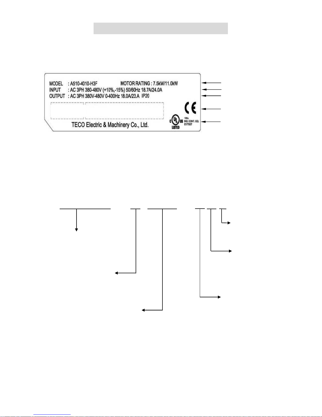
2.1 Nameplate Data
Inverter Model and Motor Rating
Input Power Specifications
Output Power Specifications
Series No.
2.2 Model Designation
UL and CE Marks
-
A510 Series
4
Voltage Rating:
2: 220V
4: 440V
6: 690V
010
- H3F
Motor Rating:
001: 1HP
002: 2HP
∫
150: 150HP
175: 175HP
215: 215HP
∫
535: 535HP
670: 670HP
Power Source Phase:
Blank: Both by single
and three phase
3: For Three phase
Noise Filter:
Blank: No RFI
F: RFI Bulit-in
Type:
H: Standard
(LED operator)
C: Drawing
(LCD operator)
(S/N Barcode)
(P/N Barcode)
Page 8

6
Chapter 3 Ambient Environment And Installation
3.1 Screw Torques for terminals
To comply with UL standards, you shall use UL approved copper wires (rated 75 ° C) and
round crimp terminals (UL Listed products) in the following table when connecting the main circuit
terminal. TECO recommends using crimp terminals manufactured by NICHIFU Terminal Industry
Co., Ltd and the terminal crimping tool recommended by the manufacturer for crimping terminals
and the insulating sleeve.
Wire size
mm2 (AWG)
Terminal
screw size
Model of
the round
crimp
terminal
Fastening torque
kgf.cm (in.lbs)
Model of
insulating
sleeve
Model of
crimp tool
0.75 (18)
M3.5 R1.25-3.5 8.2 to 10 (7.1 to 8.7) TIC 1.25 NH 1
M4 R1.25-4 12.2 to 14 (10.4 to 12.1) TIC 1.25 NH 1
1.25 (16)
M3.5 R1.25-3.5 8.2 to 10 (7.1 to 8.7) TIC 1.25 NH 1
M4 R1.25-4 12.2 to 14 (10.4 to 12.1) TIC 1.25 NH 1
2 (14)
M3.5 R2-3.5 8.2 to 10 (7.1 to 8.7) TIC 2 NH 1 / 9
M4 R2-4 12.2 to 14 (10.4 to 12.1) TIC 2 NH 1 / 9
M5 R2-5 22.1 to 24 (17.7 to 20.8) TIC 2 NH 1 / 9
M6 R2-6 25.5 to 30.0 (22.1 to 26.0) TIC 2 NH 1 / 9
3.5/5.5 (12/10)
M4 R5.5-4 12.2 to 14 (10.4 to 12.1) TIC 5.5 NH 1 / 9
M5 R5.5-5 20.4 to 24 (17.7 to 20.8) TIC 5.5 NH 1 / 9
M6 R5.5-6 25.5 to 30.0 (22.1 to 26.0) TIC 5.5 NH 1 / 9
M8 R5.5-8 61.2 to 66.0 (53.0 to 57.2) TIC 5.5 NH 1 / 9
8 (8)
M4 R8-4 12.2 to 14 (10.4 to 12.1) TIC 8 NOP 60
M5 R8-5 20.4 to 24 (17.7 to 20.8) TIC 8 NOP 60
M6 R8-6 25.5 to 30.0 (22.1 to 26.0) TIC 8 NOP 60
M8 R8-8 61.2 to 66.0 (53.0 to 57.2) TIC 8 NOP 60
14 (6)
M4 R14-4 12.2 to 14 (10.4 to 12.1) TIC 14 NH 1 / 9
M5 R14-5 20.4 to 24 (17.7 to 20.8) TIC 14 NH 1 / 9
M6 R14-6 25.5 to 30.0 (22.1 to 26.0) TIC 14 NH 1 / 9
M8 R14-8 61.2 to 66.0 (53.0 to 57.2) TIC 14 NH 1 / 9
22 (4)
M6 R22-6 25.5 to 30.0 (22.1 to 26.0) TIC 22 NOP 60/ 150H
M8 R22-8 61.2 to 66.0 (53.0 to 57.2) TIC 22 NOP 60/ 150H
30/38 (3 / 2)
M6 R38-6 25.5 to 30.0 (22.1 to 26.0) TIC 38 NOP 60/ 150H
M8 R38-8 61.2 to 66.0 (53.0 to 57.2) TIC 38 NOP 60/ 150H
50 / 60
(1 / 1/ 0)
M8 R60-8 61.2 to 66.0 (53.0 to 57.2) TIC 60 NOP 60/ 150H
M10 R60-10 102 to 120 (88.5 to 104) TIC 60 NOP 150H
70 (2/0)
M8 R70-8 61.2 to 66.0 (53.0 to 57.2) TIC 60 NOP 150H
M10 R70-10 102 to 120 (88.5 to 104) TIC 60 NOP 150H
80 (3/0)
M10 R80-10 102 to 120 (88.5 to 104) TIC 80 NOP 150H
M16 R80-16 255 to 280 (221 to 243) TIC 80 NOP 150H
100 (4/0)
M10 R100-10 102 to 120 (88.5 to 104) TIC 100 NOP 150H
M12 R100-12 143 to 157 (124 to 136) TIC 100 NOP 150H
M16 R80-16 255 to 280 (221 to 243) TIC 80 NOP 150H
Page 9

7
3.2 Wiring the periphery devices of A510
電源
無熔絲開關 NFB
(及漏電斷路器)
電磁接觸器
AC 電抗器
輸入側雜訊
濾波器
變頻器
零相雜訊濾波器
三相感應
馬達
外加高速保險絲
■ No fuse breaker (NFB) and Leakage Circuit Breaker
‧
Please refer to table 3 for choosing NFB of appropriate
current.
‧ Do not use NFB to control the start/stop of the inverter.
‧
If a leakage circuit breaker is added for leakage
protection, its current sensitivity shall be more than
200mA and action time more than 0.1 (V-TYPE),
so as
to avoid high-frequency malfunction.
■ Electromagnetic contactor
‧ It can not add the electromagnetic contactor
for general
use. However, for the application requiring
external
sequence control or automatic restart function after
power cut, an electromagnetic contactor is required.
‧ Please
avoid using electromagnetic contactor for the
start/stop control of the inverter as possible.
■ AC reactor
‧ In case of further improving
the power factor or suppress
the external surge, an AC reactor can be
additionally
equipped.
■ Fast acting fuse
‧ To protect interface devices, it is necessary to
add a fast
acting fuse (fuse specification will be referred to Section
6.6 in completed manual.)
■ Input Noise filter
‧ A510 is matched with TECO special filter, meeting the EN
55011 class A criterion.
‧ The selection of input noise filter can be referred to
Section 6.4 in completed manual.)
■ Inverter
‧ Terminal R,S,T at input side have no phase sequence
requirement, thus they can be arbitrarily exchanged.
‧ Terminal E must be well grounded.
■ Zero-phase noise filter
‧ Adding a zero-
phase noise filter at the output side of the
inverter can decrease the
radiated interference and
induced noise.
‧ Please refer to Section 6.5 in completed manual.
■ Motor
‧
If an inverter drives multiple motors, the rated current of
the inverter must be greater than the total
current that all
motors operate at the same time.
‧ Motor and inverter must be grounded respectively.
Power supply
No Fuse Breaker
(NFB) and Leakage
Circuit Breaker
Leakage Circuit
Electromagnetic
contactor
AC reactor
Fast acting fuse
Input Noise filter
Inverter
Zero-phase
noise filter
3-phase
induction
motor
Page 10

8
3.3 Wiring
The following is the standard wiring diagram for the A510 inverter ( indicates main ◎
circuit terminal, ○ indicates control circuit terminal ). Locations and symbols of the wiring
terminal block might be different due to different models of A510. The description of main
circuit terminal and control circuit terminal can be referred to table 1 and 2.
MCNFB
外加高速保險絲
B1/P B2
煞車電阻
R/L1
S/L2
S1
S2
S8
S7
S6
S5
S4
S3
類比輸出1
多
機
能
接
點
輸
入
24V
數位信號電源端子
24VG
數位信號共同端子
故障重置
正向運轉/停止
多段速指令1
寸動指令
外部Base block
Source(PNP)
SW3
AO1
AO2
GND
E
CN3
類比輸出2
E
T/L3
U/T1
V/T2
W/T3
CN6 (RJ45)
1
2
脈波指令輸入
遮蔽線連接端子
GND 類比信號共同端子
E
+12V
類比輸入用電源
AI1 多機能類比輸入
(-10~10V/0~10V, 20K
AI2 多機能類比輸入
P
P
DO2
DOG
S(+)
S(-)
PI
PO
-12V 類比輸入用電源
P
P
IM
R2C
R1A
R1B
R1C
R2A
F1
F2
安全輸入接點
+12V, 20mA
(-10~10V/0~10V/4~20mA, 250
32K Hz. Max.
I , 出廠設定
SW2
主迴路電源
出
廠
設
定
外
部
類
比
輸
入
-10V~0~10V
4~20mA/0~10V
0V
Sink(NPN), 出廠設定
脈波輸入
反向運轉/停止
UP/增頻率命令
DOWN/減頻率命令
第三種接地
電阻值100 以下
類比信號輸出1, 2
(DC 0~10V)
選購擴充卡(PG卡)
多機能繼電器輸出
250VAC, 1A以下
30VDC, 1A以下
多機能光耦輸出
(DC 48V/50mA, Open Collector)
多機能脈波輸出
32k Hz. Max.
GND
RS485通訊埠
DO1
表隔離線,
表雙絞芯隔離絞線
P
端子符號 表示主迴路,
表示
控制迴路
*2
*1
*3
*5
*6
*5
*1:僅220V 1~25HP與440V 1~30HP(含)以下容量內建剎晶體機種主回路提供B2端子,可直接於B1, B2間連接煞車電阻。
備註說明:
*2:多機能數位輸入接點S1~S8,可透過開關SW3設置成Source(PNP)或Sink(NPN)模式。
*3:多機能類比輸入2(AI2),可透過開關SW3設置成電壓命令輸入(0~10V/-10~10V)或電流命令輸入(4~20mA)。
*4
*4:安全輸入接點F1, F2間需短接變頻器始可正常輸出,使用安全輸入時,請務必拆下F1-F2間的短接線。
*5:僅220V 3HP與440V 5HP(含)以上機種,提供-12V, R2A-R2C與PO-GND端子。
*6:僅220V 2HP與440V 3HP(含)以下機種,提供DO2端子。
*5
Braking resistor
F
ast acting fuse
Main circuit power
Default setting
Forward rotation/stop
Reversal rotation/stop
Up
Down command
Multi-step speed
command
1
Fault
Jog command
External base block
Multi-function input
D
efault setting
Analog output 1
Analog output 2
The third type grounding.
Resistance lower than 100
ohm.
Analog signal output 1, 2
Option Card (PG)
Multi-function relay output
Power terminal of digital signal
250VAC, under 1A
30VDC, under 1A
Multi-function pulse output
RS485 Communication port
Multi-function
photocoupler output
AI1 Multi-function analog input
(-10~10V/0~10V, 20KΩ)
AI2 Multi-function analog input
(-10~10V/0~10V/4~20mA, 250Ω)
Default
setting
Safety input contact
GND
Mutual terminal of analog signal
-12V Power of analog input
+12V Power of analog input, +12v,20mA
PI Pulse command input 32K Hz.
Pulse input
External analog input
Connection terminal of shielding wire
24VG Mutual terminal of digital signal
Means Isolated twisted twire
Means
isolated
wire
Terminal symbol ◎ indicates main circuit,
○ indicates control circuit
Remark:
*1: Only the master circuit of 220V1~25HP and 440 V1~30HP (included) or models of lower capacity with built-in braking resistor provide terminal B2.
The braking resistor can be connected directly between B1 and B2.
*2: The multi-function digital input terminals S1~S8 can be set to Source (PNP) or Sink (NPN) mode through the SW3.
*3: Multi-function analog input 2 (AI2) can be set to the voltage command input (0-10/-10-10v) or the current command input (4~20mA) through the
SW3.
*4: Safety input connector F1 and F2 should be shorted so that the inverter outputs properly. When the safety input is used, please be sure to remove
the short-pin between F1 and F2.
*5: Only 220 V 3HP and 440 v 5HP (included) or models above, provide terminals -12V, R2A-R2C and PO-GND.
*6. Only 220 V 2HP and 440 v 3HP (included) or models below, provide terminal DO2.
Page 11

9
3.4 Terminal Description
Table 1 Major Circuit Terminals
Terminal mark
220V: 1~25HP
440V: 1~30HP
220V: 30~100HP
440V: 40~215HP
R/L1
Power supply of th
e main terminal ( single phase, only connect
R-S)
S/L2
T/L3
B1/P
• B1/P-: DC power
supply
• B1/P-B2: externally
connected braking resistor
-
B2
• ⊕ -: DC power supply
or connect
braking detection
module
⊕
-
U/T1
Inverter output
V/T2
W/T3
E
Grounding terminal (the third type grounding)
Table 2 Main circuit terminals
Type Terminal
terminal function Signal level
Digital
input
signal
S1
Forward rotation─ stop command (default),
multi-function input terminals * 1
24 VDC, 8 mA
opto-coupler isolation
(maximum voltage of 30
Vdc, input impedance of
9.03kΩ optocoupler)
S2
Reversal rotation- stop command (default),
multi-function input terminals * 1
S3
UP increases command(default),
multi-function input terminals * 1
S4
DOWN reduces command(default),
multi-function input terminals * 1
S5
Multi-step speed frequency command 1,
multi-function input terminal* 1
S6
fault reset input, multi-function input terminal *
1
S7
JOG frequency command, multi-function input
terminal * 1
S8
External B.B.(Base Block) input,
multi-function input terminal * 1
24V
Power
supply
24V
Digital signal SOURCE sharing point (SW3
switched to SOURCE )
±15%,
Maximum output
current: 250mA( the sum
of all load )
24VG
Common terminal of Digital signals
Common point of digital signal SINK ( SW3
switched to SINK )
Page 12

10
Type Terminal
terminal function Signal level
Analog
input
signal
+12V Power for speed setting
+12V
( Maximum current , 20mA)
-12V
Only above 220V 3HP/ 440V 5HP (include)
support this terminal function
-12V
(Maximum current, 20mA)
AI1
Voltage mastering speed command (0-10V
input)/(-10V~10V input)
From 0 to +10V,
From -10V to +10V
(Input impedance
: 20KΩ)
(11bit + 1 symbol,
resolution)
AI2
Multi-function analog input terminals *2, can
use SW2 to switch voltage or current input
(0~10V)/(4-20mA)
From 0 to +10V,
From -10V to +10V
(Input impedance: 20KΩ)
From 4 to 20 mA
(Input impedance: 250KΩ)
(11bit + 1 symbol,
resolution)
GND Analog signals sharing terminal ----
E Shielding wire’s connecting terminal (Ground) ----
Analog
output
signal
AO1
Multi-
function analog output terminals *3
(0~10V output)
From 0 to 10V,
( Maximum current, 20mA )
(PWM 10KHz resolution )
AO2
Multi-
function analog output terminals *3
(0~10V output)
GND Analog signals sharing terminal
Pulse
output
signal
PO
Pulse output, BW 32KHz, only above 220V
3HP/ 440V 5HP (include)
support this
terminal function.
32KHz(max), +12V output
(load: 2.2kΩ)
GND Analog signals sharing terminal ----
Pulse
input
signal
PI
Pulse command input, frequency width of
32KHz
L: from 0.0 to 0.5V
H: from 4.0 to 13.2V
0 - 32 KHz(max)
(impedance:3.89 KΩ)
GND Analog signals sharing terminal ----
Digital
output
DO1
Multi-function(open collector resistor) output:
in operation, zero speed, frequency
consistency, consistency at any frequency,
output frequency , preparation completion,
low-voltage detection, output breaker,
rotation and frequency command,
over-torque detection, abnormal, low-voltage,
Overheat, motor overload, inverter overload,
retrying, communication error, timing
functional output device……
48Vdc, 2~50mA
Opto-coupling output
DO2
(F1 only)
DOG
Sharing terminal of the
open collector
transistor
Page 13

11
Type Terminal
terminal function Signal level
Relay
output
R1A
Relay A contact (multi-function output
terminal)
Relay B contact (multi-function output
terminal)
Relay common terminal,
With the same function as DO1/DO2
Terminal capacity:
at 250Vac, 10 mA~1A
at 30Vdc, 10 mA~1A
R1B
R1C
R2A-R2C
(above
F2)
With the same function as DO1/DO2
Terminal capacity:
at 250Vac, 10 mA~1A
at 30Vdc, 10 mA~1A
safety
input
F1
on: free rotation with safe input
off: general rotation
(i
f use external safety switch to stop, you
must remove the short circuit pin.)
24Vdc, 8mA, pull-high
F2 Safety command common terminal 24V Ground
RS-485
port
S (+)
RS485/MODBUS
Opto-coupler isolation,
differential input and output
S (-)
Grounding
E (G)
Grounding to earth
Shield the connecting terminal
----
*1:Multi-function digital input can be referred to the manual.
*2:Multi-function analog input can be referred to the manual.
*3:Multi-function analog output can be referred to the manual.
Caution
‧ Maximum output current capacity of the terminal 12V is 20mA.
‧ Multi-function analog output AO1 and AO2 are special for the analog output of
meter. Please don’t use them to the analog signal output of feedback control.
‧ Control board’s 24V & ±12V just been used for internal control, please don’t connect
to external other devices to use.
Page 14
12
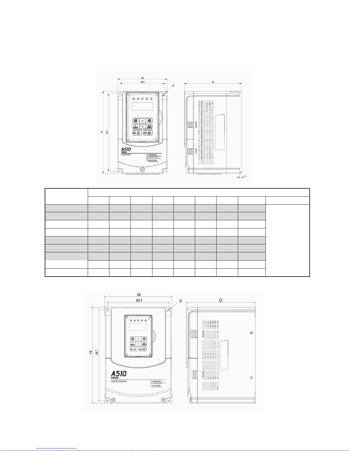
3.5 Overall Dimension drawing
3.5.1 Standard Model
(a) 220V :1-5HP/440V :1-7.5HP
Inverter Model
Dimension (mm)
W H D W1 H1 t d GW(kg)
Reactor
A510-2001-H 130 215 150 118 203 5 M5 2.2
with option
DCL
A510-2002-H 130 215 150 118 203 5 M5 2.2
A510-2003-H 140 279 177 122 267 7 M5 3.8
A510-2005-H3 140 279 177 122 267 7 M5 3.8
A510-4001-H3 130 215 150 118 203 5 M5 2.2
A510-4002-H3 130 215 150 118 203 5 M5 2.2
A510-4003-H3 130 215 150 118 203 5 M5 2.2
A510-4005-H3 140 279 177 122 267 7 M5 3.8
A510-4008-H3 140 279 177 122 267 7 M5 3.8
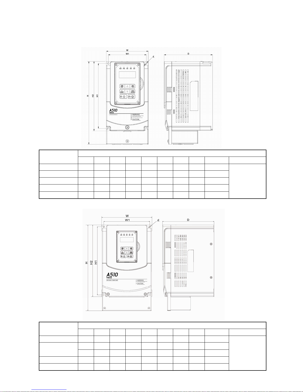
(b) 220V :7.5-25HP/440V :10-30HP
Page 15

13
Inverter Model
Dimension (mm)
W H D W1 H1 t d GW(kg)
Reactor
A510-2008-H3 210 300 215 192 286 1.6 M6 6.2
with option
ACL
A510-2010-H3 210 300 215 192 286 1.6 M6 6.2
A510-2015-H3 265 360 225 245 340 1.6 M6 10
A510-2020-H3 265 360 225 245 340 1.6 M6 10
A510-2025-H3 265 360 225 245 340 1.6 M6 10
A510-4010-H3 210 300 215 192 286 1.6 M6 6.2
A510-4015-H3 210 300 215 192 286 1.6 M6 6.2
A510-4020-H3 265 360 225 245 340 1.6 M6 10
A510-4025-H3 265 360 225 245 340 1.6 M6 10
A510-4030-H3 265 360 225 245 340 1.6 M6 10
(c) 220V :30-40HP/440V :40-60HP
Inverter Model
Dimension (mm)
W H D W1 H1 t d GW(kg)
Reactor
A510-2030-H3 284 525 252 220 505 1.6 M8 30
with option
ACL
A510-2040-H3 284 525 252 220 505 1.6 M8 30
A510-4040-H3 284 525 252 220 505 1.6 M8 30
A510-4050-H3 284 525 252 220 505 1.6 M8 30
A510-4060-H3 284 525 252 220 505 1.6 M8 30
Page 16

14
(d) 220V :50-100HP/440V :75-215HP(IP00)
Inverter Model
Dimension (mm)
W H D W1 H1 t d GW(kg)
Reactor
A510-2050-H3 344 580 300 250 560 1.6 M8 40.5
DCL
STANDARD
INCLUDED
A510-2060-H3 344 580 300 250 560 1.6 M8 40.5
A510-2075-H3 459 790 324.5 320 760 1.6 M10 74
A510-2100-H3 459 790 324.5 320 760 1.6 M10 74
A510-4075-H3 344 580 300 250 560 1.6 M8 40.5
A510-4100-H3 344 580 300 250 560 1.6 M8 40.5
A510-4125-H3 459 790 324.5 320 760 1.6 M10 74
A510-4150-H3 459 790 324.5 320 760 1.6 M10 74
A510-4175-H3 459 790 324.5 320 760 1.6 M10 74
A510-4215-H3 459 790 324.5 320 760 1.6 M10 74
Page 17

15
(e) 220V :50-100HP/440V :75-215HP(IP20)
Inverter Model
Dimension (mm)
W H D W1 H1 t d GW(kg)
Reactor
A510-2050-H3 348.5 740 300 250 560 1.6 M8 44
DCL
STANDARD
INCLUDED
A510-2060-H3 348.5 740 300 250 560 1.6 M8 44
A510-2075-H3 463.5 1105 324.5 320 760 1.6 M10 81
A510-2100-H3 463.5 1105 324.5 320 760 1.6 M10 81
A510-4075-H3 348.5 740 300 250 560 1.6 M8 44
A510-4100-H3 348.5 740 300 250 560 1.6 M8 44
A510-4125-H3 463.5 1105 324.5 320 760 1.6 M10 81
A510-4150-H3 463.5 1105 324.5 320 760 1.6 M10 81
A510-4175-H3 463.5 1105 324.5 320 760 1.6 M10 81
A510-4215-H3 463.5 1105 324.5 320 760 1.6 M10 81
Note: 250HP or above are being developed
Page 18
16
3.5.2 Built-in filter model (440V 1~60HP)
(a) 440V :1-7.5HP
Inverter Model
Dimension (mm)
W H D W1 H1 H2 t d GW(kg)
Reactor
A510-4001-H3F 130 265
150 118 203 215
5 M5 2.83
with option
ACL
A510-4002-H3F 130 265 150 118 203 215
5 M5 2.83
A510-4003-H3F 130 265 150 118 203 215
5 M5 2.83
A510-4005-H3F 140 349
177 124 266 279
7 M5 4.72
A510-4008-H3F 140 349 177 124 266 279
7 M5 4.72
(b) 440V :10-30HP
Inverter Model
Dimension (mm)
W H D W1 H1 H2 t d GW(kg)
Reactor
A510-4010-H3F 210 385 215 192 286 300 1.6 M6 7.72
with option
DCL
A510-4015-H3F 210 385 215 192 286 300 1.6 M6 7.72
A510-4020-H3F 265 480 225 245 340 360 1.6 M6 11.6
A510-4025-H3F 265 480 225 245 340 360 1.6 M6 11.6
A510-4030-H3F 265 480 225 245 340 360 1.6 M6 11.6
Page 19

17
(c) 440V :40-60HP
Inverter Model
Dimension (mm)
W H D W1 H1 H2 t d GW(kg)
Reactor
A510-4040-H3F 284 695 252 220 505 525 1.6 M8 32.24
with option
ACL
A510-4050-H3F 284 695 252 220 505 525 1.6 M8 32.24
A510-4060-H3F 284 695 252 220 505 525 1.6 M8 32.24
Page 20

18
Chapter 4 Software Index
4.1 Keypad Description
4.1.1 Panel Functions
Type Name Functions
Display
Main display area
Display frequency, parameter voltage, current, temperature and
abnormity and ect.
LED status display
FAULT: When the inverter has a warning or fault message, the
indicator lights up.
FWD: When the inverter is in forward rotation status, the
indicator lights up.
(long bright light while inverter running, flicker while
inverter stopping)
REV: When the inverter is in reversal rotation status, the
indicator lights up.
(long bright light while inverter running, flicker while
inverter stopping)
SEQ: When inverter’s run command source is set to external
control, the indicator lights up.
REF: When inverter’s frequency command source is set to
external control, the indicator lights up.
Keys
(
((
(8 keys)
))
)
RUN RUN: Enable the inverter run operation.
STOP STOP: Enable the inverter stop operation.
▲
It is used for frequency and parameter setting.
▼ It is used for frequency and parameter setting.
FWD/REV
This key is used for switching motor’s rotation direction. FWD
indicator on means the motor is rotating in forward direction;
REV indicator on means the motor is rotating in reversal
direction.
DSP/FUN
It is use for switching dispay interface, based on the loop of
frequency screen function selectionmonitor parameter
frequency screen.
Page 21

19
</RESET
“<” is left shift key. It is used for changing parameter or value.
RESET key: when a fault is detected, it plays reset function .
READ/ENTER
Switch to enter the functions and set internal value, as well as
modify parameter setting and confirm the writing.
4.2 Parameters list
Parameter group Name
Group00 Basic Function Group
Group01 V/F Control Function Group
Group02 IM Motor Parameter Group
Group03
External Terminals Digital Input/Output Function Group
Group04 External terminal analog signal input (output) function group
Group05 Multi-Speed Group
Group06 Automatic Programm Operation Function Group
Group07 Operation /Stop Function Group
Group08 Protection Function Group
Group09 Communication Function Group
Group10 PID Function Group
Group11 Auxiliary Function Group
Group12 Monitoring Function Group
Group13 Maintenance Function Group
Group14 PLC Setting Group
Group15 PLC Monitoring Group
Group16 LCM Function Group
Group17 Automatic Tuning Function Group
Group18 Slip Compensation Group
Group19 Frequency Wobble Function Group
Group20 Speed Control Function Group
Group21 Torque And Position Control Function Group
Group22 IPM Motor Parameter Group
Parameter Attribute
*1
Modifiable paramters in operation
*2
Unmodifiable parameters in communication
*3
When carry out the factory default setting, this parameter value(set by users) will not restore the
factory default.
*4
Readable and unmodifiable parameter
Page 22

20
Group 00 Basic Function Group
Code
Parameter Name Range Default Unit
Control mode
Attrib
ute
V/F
V/F
+PG
SLV SV
PM
SV
PM
SLV
00-00
Control mode
Selection
0: V/F
0 - O O O O O O *3
1: V/F+PG
2: SLV
3: SV
4: PMSV
5:retain
00-01
Motor’s rotation
direction
0:forward direction
0 - O O O O O O *1
1:reversal direction
00-02
RUN Command
Selection
0:keypad control
1 - O O O O O O
1: external control
2: Communication control
3:PLC
00-03 Retain
00-04 Retain
00-05
Main Frequency
Command Source
Selection
0: keypad
1 - O O O O O O
1: external control (Analog)
2:Terminal UP/DOWN
3: Communication control
4:pulse input
5:PID
00-06 Retain
00-07 Retain
00-08
Communication
frequency command
0.00-400.00
0.0~1200.0 (when 00-31 = 1)
0.00 Hz O O O O O O
00-09
Frequency
command
memory mode
0:Don’t save when power
supply is cut.
0 - O O O O O O
1: Save when power is off.
00-10 Retain
00-11 Retain
00-12 Upper frequency limit 0.1~109.0 100.0 % O O O O O O
00-13 Lower frequency limit 0.0~109.0 0.0 % O O O O O O
00-14 Acceleration time 1 0.1~6000.0 10.0 s O O O O O O *1
00-15 Deceleration time 1 0.1~6000.0 10.0 s O O O O O O *1
00-16 Acceleration time 2 0.1~6000.0 10.0 s O O O O O O *1
00-17 Deceleration time 2 0.1~6000.0 10.0 s O O O O O O *1
00-18 Jog frequency
0.00~400.00
0.0~1200.0 (when 00-31 = 1)
6.00 Hz O O O O O O *1
00-19 Jog acceleration time 0.1~0600.0 10.0 s O O O O O O *1
00-20 Jog deceleration time 0.1~0600.0 10.0 s O O O O O O *1
00-21 Acceleration time 3 0.1~6000.0 10.0 s O O O O O O *1
00-22 Deceleration time 3 0.1~6000.0 10.0 s O O O O O O *1
00-23 Acceleration time 4 0.1~6000.0 10.0 s O O O O O O *1
00-24 Deceleration time 4 0.1~6000.0 10.0 S O O O O O O *1
00-25
Switching frequency of
acceleration and
deceleration
0.0~400.0
0.0~1200.0 (when 00-31 = 1)
0.0 Hz O O O O O O
Page 23
21
Code
Parameter Name Range Default Unit
Control mode
Attrib
ute
V/F
V/F
+PG
SLV SV
PM
SV
PM
SLV
00-26 Emergency stop time 0.1~6000.0 5.0 s O O O O O O
00-27 HD/ND selection
0: HD (heavy load mode)
0 - O O X X X X *3
1: ND (general load mode)
00-28
Command
characteristic selection
of master frequency
0: positive characteristic
(0~10V/4~20mA is
corresponding to 0~100%)
0 - O O O O O O
1: negative characteristic
(0~10V/4~20mA is
corresponding to 100~0%)
00-29
Zero-speed operation
selection
0: Operation based on
frequency command
0 - X X X O O X
1: Stop
2: Operation based on the
lowest frequency
3: Zero-speed operation
00-30
Retain
00-31 Maximum frequency
0: 400.00Hz
0 - O O X X X X *3
1:1200.0Hz
00-32
Application
adjustment
0: Disable
0 - O O O O O O
1: Water supply pump
2: Conveyor
3: Exhaust fan
4: HVAC
5: Compressor
6: Hoist
7: Crane
Group 01 V/F Control Function Group
Code Parameter Name Range Default Unit
Control mode
Attrib
ute
V/F
V/F
+PG
SL
V
SV
PM
SV
PM
SLV
01-00 V/F curve selection 0~FF F - O O X X X X *3
01-01 Retain
01-02
Maximum output
frequency of motor 1
40.0~400.0
40.0~1200.0 (when 00-31 = 1)
60.0 Hz O O O O O O
01-03
Maximum output
voltage of motor 1
200V: 0.1~255.0 220.0
V O O X X X X
400V: 0.2~510.0 440.0
01-04
Middle Output
frequency 2 of motor 1
0.0~400.0
0.0~1200.0 (when 00-31 = 1 )
0.0 Hz O O X X X X
01-05
Middle
Output voltage 2
of motor 1
200V: 0.0~255.0
0.0 V O O X X X X
400V: 0.0~510.0
01-06
Middle Output
frequency 1 of motor 1
0.0~400.0
0.0~1200.0 (when 00-31 = 1 )
3.0 Hz O O X X X X
01-07
Middle
Output voltage 1
of motor 1
200V: 0.0~255.0 14.0
V O O X X X X
400V: 0.0~510.0 28.0
Page 24

22
Code
Parameter Name Range Default Unit
Control mode
Attrib
ute
V/F
V/F
+PG
SLV SV
PM
SV
PM
SLV
01-08
Minimum output
frequency of motor 1
0.0~400.0
0.0~1200.0 (when 00-31 = 1 )
1.5 Hz O O O O O O
01-09
Minimum output
voltage of motor 1
200V: 0.0~255.0 7.5
V O O X X X X
400V: 0.0~510.0 15.0
01-10
T
orque compensation
gain
0.0~2.0 1.0 - O O X X X X *1
01-11 Retain
01-12
Base frequency of
motor 1
10.0~400.0
10.0~1200.0 (when 00-31 = 1)
60.0 Hz O O O O O O
01-13
Base output voltage of
motor 1
200V: 0.0~255.0 220.0
V O O X X X X
400V: 0.0~510.0 440.0
01-14 Input voltage setting
200V: 155.0~255.0 220.0
V O O O O O O
400V: 310.0~510.0 440.0
01-15
Torque compensation
time
1~10000 200 ms O O X X X X
01-16
Maximum output
frequency of motor 2
40.0~400.0
40.0~1200.0 (when 00-31 = 1)
60.0 Hz O O O O O O
01-17
Maximum output
voltage of motor 2
200V: 0.1~255.0 220.0
V O O X X X X
400V: 0.2~510.0 440.0
01-18
Middle Output
frequency 2 of motor 2
0.0~400.0
0.0~1200.0 (when 00-31 = 1)
0.0 Hz O O X X X X
01-19
Middle
Output voltage 2
of motor 2
200V: 0.0~255.0
0.0 V O O X X X X
400V: 0.0~510.0
01-20
Middle output
frequency 1 of motor 2
0.0~400.0
0.0~1200.0 (when 00-31 = 1)
3.0 Hz O O X X X X
01-21
Middle
output voltage 1
of motor 2
200V: 0.0~255.0 14.0
V O O X X X X
400V: 0.0~510.0 28.0
01-22
Minimum output
frequency of motor 2
0.0~400.0
0.0~1200.0 (when 00-31 = 1)
1.5 Hz O O O O O O
01-23
Minimum output
voltage of motor 2
200V: 0.0~255.0 7.5
V O O X X X X
400V: 0.0~510.0 15.0
01-24
Base frequency of
motor 2
10.0~400.0
10.0~1200.0 (when 00-31 = 1)
60.0 Hz O O O O O O
01-25
Base output voltage of
motor 2
200V: 0.0~255.0 220.0
V O O X X X X
400V: 0.0~510.0 440.0
Page 25

23
Group 02 IM Motor parameter group
Code
Parameter Name Range Default Unit
Control mode
Attrib
ute
V/F
V/F
+PG
SLV SV
PM
SV
PM
SLV
02-00
No-Load Current of
motor1
0.01~600.00 - A O X X X X X
02-01
Rated current of motor1
Modes of V/F, V/F+PG are
10%~200%
of inverter’s rated
current. Modes of SLV, SV are
25%~200%
of inverter’s rated
current.
- A O O O O X X
02-02 Retain
02-03
Rated rotation speed of
motor1
0~60000 -
Rpm
O O O O X X
02-04
Rated voltage of
motor1
200V: 50.0~240.0 220.0
V O O O O X X
400V: 100.0~480.0 440.0
02-05
Rated power of motor1
0.01~600.00 - kW O O O O X X
02-06
Rated frequency of
motor1
10.0~400.0
10.0~1200.0 (when 00-31 = 1)
60.0 Hz O O O O X X
02-07 Poles of motor 1 2,4,6,8 4 - O O O O X X
02-08 Retain
02-09
Excitation current of
motor 1
10.0~100.0 - % X X O O X X
02-10
Core saturation
coefficient 1 of motor 1
0~100 - % X X O O X X
02-11
Core saturation
coefficient 2 of motor 1
0~100 - % X X O O X X
02-12
Core saturation
coefficient 3 of motor 1
80~300 - % X X O O X X
02-13 Core loss of motor 1 0.0~15. 0 - % O O X X X X
02-14 Retain
02-15
Resistance between
wire
s of motor 1
0.001~60.000 - Ω O O O O X X
02-16
Rotor resistanceof of
motor 1
0.001~60.000 - Ω X X O O X X
02-17
Leakage inductance of
motor 1
0.01~200.00 - mH X X O O X X
02-18
Mutual inductance of
motor 1
0.1~6553.5 - mH X X O O X X
02-19
No-Load Voltage of
motor 1
200V: 50~240 -
V X X O O X X
400V: 100~480 -
02-20
No-Load Current of
motor2
0.01~600.00 - A O X X X X X
02-21
Rated current of motor
2
10%~200%
of inverter’s rated
current
- A O O O O X X
02-22
Rated rotation speed of
motor 2
0~60000 -
Rpm
O O O O X X
02-23
Rated voltage of motor
2
200V: 50.0~240.0 220.0
V O O O O X X
400V: 100.0~480.0 440.0
02-24
Rated power of motor 2
0.01~600.00 - kW O O O O X X
Page 26

24
Code
Parameter Name Range Default Unit
Control mode
Attrib
ute
V/F
V/F
+PG
SLV SV
PM
SV
PM
SLV
02-25
Rated frequency of
motor 2
10.0~400.0
10.0~1200.0 (when 00-31 = 1)
60.0 Hz O O O O X X
02-26 Poles of motor 2 2,4,6,8 4 - O O O O X X
02-27 Retain
02-28 Retain
02-29 Retain
02-30 Retain
02-31 Retain
02-32
Resistnce between
wires of motor 2
0.001~60.000 - Ω O O O O X X
02-33 Retain
02-34 Retain
02-35 Retain
02-36 Retain
Group 03 External terminal digital signal input (output) function group
Code
Parameter Name Range Default Unit
Control mode
Attrib
ute
V/F
V/F
+PG
SLV SV
PM
SV
PM
SLV
03-00
Multi-function terminal
Function setting-S1
0: 2-Wire sequence (ON :
Forward run command).
1: 2-Wire sequence (ON :
Reverse run command).
2: Multi-speed/position setting
command 1
3: Multi-speed/position setting
command 2
4: Multi-speed/position setting
command 3
5: Multi-speed/position setting
command 4
6 : Forward jog run command
7 : Reverse jog run command
8 : UP frequency increasing
command
9: DOWN frequency
decreasing command
10: Acceleration/deceleration
setting command 1
11: Inhibit
Acceleration/deceleration
Command
12: Retain
13: Retain
14: Emergency stop
0 - O O O O O O
03-01
Multi-function terminal
Function setting-S2
1 - O O O O O O
03-02
Multi-function terminal
Function setting-S3
8 - O O O O O O
03-03
Multi-function terminal
Function setting-S4
9 - O O O O O O
03-04
Multi-function terminal
Function setting-S5
2 - O O O O O O
03-05
Multi-function terminal
Function setting-S6
17 - O O O O O O
03-06
Multi-function terminal
Function setting-S7
Two-
wire
type:29
Three-wir
e type:26
- O O O O O O
03-07
Multi-function terminal
Function setting-S8
15 - O O O O O O
Page 27

25
Group 03 External terminal digital signal input (output) function group
Code
Parameter Name Range Default Unit
Control mode
Attrib
ute
V/F
V/F
+PG
SLV SV
PM
SV
PM
SLV
(decelerate to zero and stop)
15: External Baseblock
Command(rotation freely to
stop)
16 : PID control disable
17: Fault reset (RESET)
18: Retain
19: Speed Search 1(from the
maximum frequency)
20: Manual energy saving
function
21: PID integral reset
22 : Retain
23 : Retain
24: PLC input
25: External fault
26: 3-Wire sequence
(Forward/Reverse command).
27: Local/Remote selection
28: Remote mode selection
29: Jog frequency selection
30: Acceleration/deceleration
setting command 2
31: Inverter overheating
warning
32: Sync command
33: DC braking
34: Speed Search 2 (from the
frequency command)
35: Timing function input
36: PID Soft start invalid
37: Traversing operation
38 : Upper Deviation of
traverse operation
39 : Lower Deviation of
traverse operation
40: Switching between motor
1/motor 2
41: Retain
42: PG invalid
43: PG integral reset
44: Mode switching between
speed and torque
45: Negative torque command
46 : Zero-Servo Command
47: Fire Mode
48: KEB acceleration
49:Parameters writing
allowable
Page 28

26
Group 03 External terminal digital signal input (output) function group
Code
Parameter Name Range Default Unit
Control mode
Attrib
ute
V/F
V/F
+PG
SLV SV
PM
SV
PM
SLV
50 : Unattended Start
Protection (USP)
51: Mode switching between
speed and position
03-08 (S1~S8)DI Scan time
0: Scan time 4ms
1: Scan time 8ms
1 - O O O O O O
03-09
Multi-
function terminal
S1-S4 type selection
xxx0b: S1 A contact
xxx1b: S1
B contact
0000b - O O O O O O
xx0xb: S2 A contact
xx1xb: S2
B contact
x0xxb: S3 A contact
x1xxb: S3
B contact
0xxxb: S4 A contact1
xxxb: S4
B contact
03-10
Multi-function terminal
S5-S8 type selection
xxx0b: S5 A contact
xxx1b: S5
B contact
0000b - O O O O O O
xx0xb: S6 A contact
xx1xb: S6
B contact
x0xxb: S7 A contact
x1xxb: S7
B contact
0xxxb: S8 A contact
1xxxb: S8
B contact
03-11
Relay (R1A-R1C)
output
0: Durning Running
1: Fault contact output
2: Frequency Agree
3: Setting Frequency Agree
4: Frequency detection 1 (>
03-13)
5: Frequency detection 2 (<
03-13)
6: Automatic restart
7: Retain
8: Retain
9: Baseblock
10: Retain
11: Retain
12: Over torque detection
13: Retain
14: Retain
15: Retain
16: Retain
17: Retain
18: PLC status
19: PLC control contact
20: zero speed
21: Inverter Ready
22: Undervoltage Detection
23: Source of operation
command
1 - O O O O O O
03-12
Relay (R2A-R2C)
output
20 - O O O O O O
Page 29

27
Group 03 External terminal digital signal input (output) function group
Code
Parameter Name Range Default Unit
Control mode
Attrib
ute
V/F
V/F
+PG
SLV SV
PM
SV
PM
SLV
24: Source of frequency
command
25: Low torque detection
26: Frequency Reference
missing
27: Timing function output
28: Traverse operation UP
Status
29 : During Traverse operation
status
30 : Motor 2 Selection
31 : Zero Servo Completed
32: Communication control
contacts
03-13
Frequency detection
Level
0.0~400.0
0.0~1200.0 (when 00-31 = 1)
0.0 Hz O O O O O O
03-14
Frequency detection
width
0.1~25.5 2.0 Hz O O O O O O
03-15 Retain
03-16 Retain
03-17 Retain
03-18 Retain
03-19 Relay (R1A-R2C) type
xxx0b: R1 A contact
xxx1b: R1
B contact
0000b - O O O O O O
xx0xb: R2 A contact
xx1xb: R2
B contact
03-20 Retain
03-21 Retain
03-22 Retain
03-23 Retain
03-24 Retain
03-25 Retain
03-26
Retain
03-27
UP/DOWN frequency
maintaining selection
0: maintain UP/DOWN
frequency when stopping
0 - O O O O O O
1: clear UP/DOWN
frequency
when stopping
2: allow UP/DOWN
frequency
when stopping
03-28 Optocoupler output
Range and definition are the
same as those of 03-11,
03-12
0 - O O O O O O
03-29
optocoupler output
selection
xxx0b: optocoupler A contact
xxx1b: optocoupler B contact
0000b - O O O O O O
03-30
Function setting of
pulse input
0: Frequency command
0 - O O O O O O
1: PID feedback
2: PID target value
3: Retain
Page 30

28
Group 03 External terminal digital signal input (output) function group
Code
Parameter Name Range Default Unit
Control mode
Attrib
ute
V/F
V/F
+PG
SLV SV
PM
SV
PM
SLV
03-31 Scale of pulse input 50~32000 1000 Hz O O O O O O *1
03-32 Gain of pulse input 0.0~1000.0 100 % O O O O O O *1
03-33
Bias voltage of pulse
input
-100.0~100.0 0.0 % O O O O O O *1
03-34
Filter time of pulse
input
0.00~2.00 0.1 Sec O O O O O O *1
03-35
Function setting of
pulse output
1: Frequency command
2 - O O O O O O *1
2: Output frequency
3: Output frequency after
soft-start
4: motor speed
5: PID feedback
6: PID input
7: PG output
03-36 Scale of pulse output 1~32000 1000 Hz O O O O O O *1
03-37 Timer ON delay (DIO) 0.0~6000.0 0.0 s O O O O O O
03-38 Timer OFFdelay (DIO) 0.0~6000.0 0.0 s O O O O O O
Page 31

29
Group 04 External terminal analog signal input(output) function group
Code Parameter Name Range Default Unit
Control mode
Attrib
ute
V/F
V/F
+PG
SLV SV
PM
SV
PM
SLV
04-00 AI input signal type
0: AI1:0~10V AI2:
0~10V
1 - O O O O O O
1: AI1:0~10V AI2:
4~20mA
2: AI1: -10~10V AI2:
0~10V
3: AI1: -10~10V AI2:
4~20mA
04-01
AI1
signal scanning
and filtering time
0.00~2.00 0.03 s O O O O O O
04-02 AI1gain value 0.0~1000.0 100.0 % O O O O O O *1
04-03 AI1bias voltage value -100.0~100.0 0 % O O O O O O *1
04-04 Retain
04-05 AI2 function setting
0: Auxiliary Frequency
10 - O O O O O O
1: Frequency Reference Gain
2: Frequenc
y Reference Bias
3: Output Voltage Bias
4:
Coefficient of acceleration
and deceleration reduction
5: DC braking current
6: Over-torque detection level
7:
Stall prevention Level During
Running
8:Frequency lower limit
9:Jump frequency 4
10: Added to AI1
11: Positive torque limit
12: Negative torque limit
13: Regenerative Torque Limit
14: Positive / negative torque
limit
15: Torque Reference/Torque
Limit (in speed control)
16: Torque compensation
17: No function
04-06
AI2
signal scanning
and filtering time
0.00~2.00 0.03 s O O O O O O
04-07 AI2 gain value 0.0~1000.0 100.0 % O O O O O O *1
04-08 AI2 bias voltage value -100.0~100.0 0 % O O O O O O *1
04-09 Retain
04-10 Retain
04-11 AO1 function setting
0: Output frequency
0 - O O O O O O
1: Frequency command
2: Output voltage
3: DC voltage
4: Output current
Page 32

30
Group 04 External terminal analog signal input(output) function group
Code Parameter Name Range Default Unit
Control mode
Attrib
ute
V/F
V/F
+PG
SLV SV
PM
SV
PM
SLV
5: Output power
6: Motor Speed
7: Output power factor
8: AI1 input
9: AI2 input
10: Torque command
11: q-axis current
12: d-axis current
13: Speed deviation
14: Retain
15: ASR output
16: Retain
17: q-axis voltage
18: d-axis voltage
19: Retain
20: Retain
21: PID input
22: PID output
23: PID target value
24: PID feedback value
25:
Output frequency of the
soft starter
26: PG feedback
27: PG compensation volume
04-12 AO1 gain value 0.0~1000.0 100.0 % O O O O O O *1
04-13 AO1 bias-voltage value -100.0~100.0 0 % O O O O O O *1
04-14 Retain
04-15 Retain
04-16 AO2 function setting
Range and definition are the
same as those of 04-11
3 - O O O O O O
04-17 AO2 gain value 0.0~1000.0 100.0 % O O O O O O *1
04-18 AO2 bias-voltage value -100.0~100.0 0 % O O O O O O *1
Page 33

31
Group 05 Multi-Speed Group
Code Parameter Name Range Default Unit
Control mode
Attrib
ute
V/F
V/F
+PG
SLV SV
PM
SV
PM
SLV
05-00
Acceleration and
deceleration selection
of multi-speed
0: acceleration time is set by
deceleration time 1~4
0 - O O O O O O
1:Acceleration and
deceleration time setting
respetively
05-01
Frequency setting of
speed-stage 0
0.00~400.00
0.0~1200.0 (when 00-31 = 1)
5.00 Hz O O O O O O *1
05-02 Retain
05-03 Retain
05-04 Retain
05-05 Retain
05-06 Retain
05-07 Retain
05-08 Retain
05-09 Retain
05-10 Retain
05-11 Retain
05-12 Retain
05-13 Retain
05-14 Retain
05-15 Retain
05-16 Retain
05-17
Acceleration time
setting of multi speed 0
0.1~6000.0 10.0 s O O O O O O
05-18
Deceleration time
setting of multi speed 0
0.1~6000.0
10.0 s O O O O O O
05-19
Acceleration time
setting of multi speed 1
0.1~6000.0
10.0 s O O O O O O
05-20
Deceleration time
setting of multi speed 1
0.1~6000.0
10.0 s O O O O O O
05-21
Acceleration time
setting of multi speed 2
0.1~6000.0
10.0 s O O O O O O
05-22
Deceleration time
setting of multi speed 2
0.1~6000.0
10.0 s O O O O O O
05-23
Acceleration time
setting of multi speed 3
0.1~6000.0
10.0 s O O O O O O
05-24
Deceleration time
setting of multi speed 3
0.1~6000.0
10.0 s O O O O O O
05-25
Acceleration time
setting of multi speed 4
0.1~6000.0
10.0 s O O O O O O
05-26
Deceleration time
setting of multi speed 4
0.1~6000.0
10.0 s O O O O O O
05-27
Acceleration time
setting of multi speed 5
0.1~6000.0
10.0 s O O O O O O
05-28
Deceleration time
setting of multi speed 5
0.1~6000.0
10.0 s O O O O O O
05-29 Acceleration time 0.1~6000.0 10.0 s O O O O O O
Page 34

32
Group 05 Multi-Speed Group
Code Parameter Name Range Default Unit
Control mode
Attrib
ute
V/F
V/F
+PG
SLV SV
PM
SV
PM
SLV
setting of multi speed 6
05-30
Deceleration time
setting of multi speed 6
0.1~6000.0
10.0 s O O O O O O
05-31
Acceleration time
setting of multi speed 7
0.1~6000.0
10.0 s O O O O O O
05-32
Deceleration time
setting of multi speed 7
0.1~6000.0
10.0 s O O O O O O
05-33
Acceleration time
setting of multi speed 8
0.1~6000.0
10.0 s O O O O O O
05-34
Deceleration time
setting of multi speed 8
0.1~6000.0
10.0 s O O O O O O
05-35
Acceleration time
setting of multi speed 9
0.1~6000.0
10.0 s O O O O O O
05-36
Deceleration time
setting of multi speed 9
0.1~6000.0
10.0 s O O O O O O
05-37
Acceleration time
setting of multi speed
10
0.1~6000.0
10.0 s O O O O O O
05-38
Deceleration time
setting of multi speed
10
0.1~6000.0
10.0 s O O O O O O
05-39
Acceleration time
setting of multi speed
11
0.1~6000.0
10.0 s O O O O O O
05-40
Deceleration time
setting of multi speed
11
0.1~6000.0
10.0 s O O O O O O
05-41
Acceleration time
setting of multi speed
12
0.1~6000.0
10.0 s O O O O O O
05-42
Deceleration time
setting of multi speed
12
0.1~6000.0
10.0 s O O O O O O
05-43
Acceleration time
setting of multi speed
13
0.1~6000.0
10.0 s O O O O O O
05-44
Deceleration time
setting of multi speed
13
0.1~6000.0
10.0 s O O O O O O
05-45
Acceleration time
setting of multi speed
14
0.1~6000.0
10.0 s O O O O O O
05-46
Deceleration time
setting of multi speed
14
0.1~6000.0
10.0 s O O O O O O
05-47
Acceleration time
setting of multi speed
15
0.1~6000.0
10.0 s O O O O O O
Page 35

33
Group 05 Multi-Speed Group
Code Parameter Name Range Default Unit
Control mode
Attrib
ute
V/F
V/F
+PG
SLV SV
PM
SV
PM
SLV
05-48
Deceleration time
setting of multi speed
15
0.1~6000.0
10.0 s O O O O O O
Group 06 Automatic Programm Operation Function Group
Code Parameter Name Range Default Unit
Control mode
Attrib
ute
V/F
V/F
+PG
SLV SV
PM
SV
PM
SLV
06-00
Automatic operation
mode selection
0: invalid
0 - O O O X O X
1: Execute a single cycle
operation mode. Restart
speed is based on the
previous stopped speed.
2: Execute continuous cycle
operation mode. Restart
speed is based on the
previous stopped speed.
3: Afte the completetion of a
single cycle, the on-going
operation speed is based on
the speed of the last stage.
Restart speed is based on
the previous stopped speed.
4: Execute a single cycle
operation mode. Restart
speed will be based on the
speed of stage 1.
5: Execute continuous cycle
operation mode. Restart
speed will be based on the
speed of stage 1.
6: Afte the completetion of a
single cycle, the on-going
operation speed is based on
the speed of the last stage.
Restart speed is based on
the previous stopped speed.
06-01
Frequency setting of
speed-stage 1
0.00~400.00
0.0~1200.0 (when 00-31 = 1)
5.00 Hz O O O O O O *1
06-02
Frequency setting of
speed-stage 2
0.00~400.00
0.0~1200.0 (when 00-31 = 1)
10.00 Hz O O O O O O *1
06-03
Frequency setting of
speed-stage 3
0.00~400.00
0.0~1200.0 (when 00-31 = 1)
20.00 Hz O O O O O O *1
06-04
Frequency setting of
speed-stage 4
0.00~400.00
0.0~1200.0 (when 00-31 = 1)
30.00 Hz O O O O O O *1
06-05
Frequency setting of
speed-stage 5
0.00~400.00
0.0~1200.0 (when 00-31 = 1)
40.00 Hz O O O O O O *1
Page 36

34
Group 06 Automatic Programm Operation Function Group
Code Parameter Name Range Default Unit
Control mode
Attrib
ute
V/F
V/F
+PG
SLV SV
PM
SV
PM
SLV
06-06
Frequency setting of
speed-stage 6
0.00~400.00
0.0~1200.0 (when 00-31 = 1)
50.00 Hz O O O O O O *1
06-07
Frequency setting of
speed-stage 7
0.00~400.00
0.0~1200.0 (when 00-31 = 1)
50.00 Hz O O O O O O *1
06-08
Frequency setting of
speed-stage 8
0.00~400.00
0.0~1200.0 (when 00-31 = 1)
5.00 Hz O O O O O O *1
06-09
Frequency setting of
speed-stage 9
0.00~400.00
0.0~1200.0 (when 00-31 = 1)
5.00 Hz O O O O O O *1
06-10
Frequency setting of
speed-stage 10
0.00~400.00
0.0~1200.0 (when 00-31 = 1)
5.00 Hz O O O O O O *1
06-11
Frequency setting of
speed-stage 11
0.00~400.00
0.0~1200.0 (when 00-31 = 1)
5.00 Hz O O O O O O *1
06-12
Frequency setting of
speed-stage12
0.00~400.00
0.0~1200.0 (when 00-31 = 1)
5.00 Hz O O O O O O *1
06-13
Frequency setting of
speed-stage 13
0.00~400.00
0.0~1200.0 (when 00-31 = 1)
5.00 Hz O O O O O O *1
06-14
Frequency setting of
speed-stage 14
0.00~400.00
0.0~1200.0 (when 00-31 = 1)
5.00 Hz O O O O O O *1
06-15
Frequency setting of
speed-stage 15
0.00~400.00
0.0~1200.0 (when 00-31 = 1)
5.00 Hz O O O O O O *1
06-16
Operation time setting
of speed-stage 0
0.0~6000.0 0.0 s O O O X X O *1
06-17
Operation time setting
of speed-stage 1
0.0~6000.0 0.0 s O O O X X O *1
06-18
Operation time setting
of speed-stage 2
0.0~6000.0 0.0 s O O O X X O *1
06-19
Operation time setting
of speed-stage 3
0.0~6000.0 0.0 s O O O X X O *1
06-20
Operation time setting
of speed-stage 4
0.0~6000.0 0.0 s O O O X X O *1
06-21
Operation time setting
of speed-stage 5
0.0~6000.0 0.0 s O O O X X O *1
06-22
Operation time setting
of speed-stage 6
0.0~6000.0 0.0 s O O O X X O *1
06-23
Operation time setting
of speed-stage 7
0.0~6000.0 0.0 s O O O X X O *1
06-24
Operation time setting
of speed-stage 8
0.0~6000.0 0.0 s O O O X X O *1
06-25
Operation time setting
of speed-stage 9
0.0~6000.0 0.0 s O O O X X O *1
06-26
Operation time setting
of speed-stage 10
0.0~6000.0 0.0 s O O O X X O *1
06-27
Operation time setting
of speed-stage 11
0.0~6000.0 0.0 s O O O X X O *1
06-28
Operation time setting
of speed-stage 12
0.0~6000.0 0.0 s O O O X X O *1
06-29
Operation time setting
of speed-stage 13
0.0~6000.0 0.0 s O O O X X O *1
Page 37

35
Group 06 Automatic Programm Operation Function Group
Code Parameter Name Range Default Unit
Control mode
Attrib
ute
V/F
V/F
+PG
SLV SV
PM
SV
PM
SLV
06-30
Operation time setting
of speed-stage 14
0.0~6000.0 0.0 s O O O X X O *1
06-31
Operation time setting
of speed-stage 15
0.0~6000.0 0.0 s O O O X X O *1
06-32
Operation direction
selection of
speed-stage 0
0: Stop 1: Forward 2:
Reversal
0 - O O O X X O
06-33
Operation direction
selection of
speed-stage 1
0: Stop 1: Forward 2:
Reversal
0 - O O O X X O
06-34
Operation direction
selection of
speed-stage2
0: Stop 1: Forward 2:
Reversal
0 - O O O X X O
06-35
Operation direction
selection of
speed-stage 3
0: Stop 1: Forward 2:
Reversal
0 - O O O X X O
06-36
Operation direction
selection of
speed-stage 4
0: Stop 1: Forward 2:
Reversal
0 - O O O X X O
06-37
Operation direction
selection of
speed-stage 5
0: Stop 1: Forward 2:
Reversal
0 - O O O X X O
06-38
Operation direction
selection of
speed-stage 6
0: Stop 1: Forward 2:
Reversal
0 - O O O X X O
06-39
Operation direction
selection of
speed-stage 7
0: Stop 1: Forward 2:
Reversal
0 - O O O X X O
06-40
Operation direction
selection of
speed-stage 8
0: Stop 1: Forward 2:
Reversal
0 - O O O X X O
06-41
Operation direction
selection of
speed-stage 9
0: Stop 1: Forward 2:
Reversal
0 - O O O X X O
06-42
Operation direction
selection of
speed-stage 10
0: Stop 1: Forward 2:
Reversal
0 - O O O X X O
06-43
Operation direction
selection of
speed-stage 11
0: Stop 1: Forward 2:
Reversal
0 - O O O X X O
06-44
Operation direction
selection of
speed-stage 12
0: Stop 1: Forward 2:
Reversal
0 - O O O X X O
06-45
Operation direction
selection of
speed-stage13
0: Stop 1: Forward 2:
Reversal
0 - O O O X X O
06-46
Operation direction
selection of
0: Stop 1: Forward 2:
Reversal
0 - O O O X X O
Page 38

36
Group 06 Automatic Programm Operation Function Group
Code Parameter Name Range Default Unit
Control mode
Attrib
ute
V/F
V/F
+PG
SLV SV
PM
SV
PM
SLV
speed-stage 14
06-47
Operation direction
selection of
speed-stage 15
0: Stop 1: Forward
2: Reversal
0 - O O O X X O
Group 07 Start /Stop Function Group
Code Parameter Name Range Default Unit
Control mode
Attrib
ute
V/F
V/F
+PG
SLV SV
PM
SV
PM
SLV
07-00
Momentary stop and
restart selection
0:invalid
0 - O O O O O O
1:valid
07-01
Restart time of
automatic reset
0~7200 0 s O O O O O O
07-02
Times of automatic
reset
0~10 0 - O O O O O O
07-03 Retain
07-04 Retain
07-05 Retain
07-06
DC Injection Braking
Starting Frequency
0.0~10.0 0.5 Hz O O O O X X
07-07
DC Injection Braking
Current
0~100 50 % O O O O X X
07-08
DC Injectio
n Braking
Time at Stop
0.00~10.00 0.50 s O O O O X X
07-09 Stop mode selection
0: Deceleration to stop
0 - O O O O O O
1: Coast to stop
2: DC braking stop in all fields
3: Coast to stop with timer
07-10 Retain
07-11 Retain
07-12 Retain
07-13
Low
voltage Detection
Level
200V: 150~210 190
V O O O O O O
400V: 300~420 380
07-14
Maximum
pre-excitation time
0.00~10.00 2.00 s X X O X X X
07-15 Pre-excitation Level 100~200 100 % X X O X X X
07-16
DC Inje
ction Braking
Time at Start
0.00~10.00 0.00 s O O O O O O
07-17 Retain
07-18
Minimum Base
block
Time
0.1~5.0 - Sec O O O X X O
07-19
Speed Direction Search
Operating Current
0~100 50 % O X O X X O
07-20
Speed Search
Operating Current
0~100 20 % O X O X X O
07-21
Integral time of speed
0.1~10.0 2.0 Sec O X O X X O
Page 39

37
Group 07 Start /Stop Function Group
Code Parameter Name Range Default Unit
Control mode
Attrib
ute
V/F
V/F
+PG
SLV SV
PM
SV
PM
SLV
searching
07-22
Delay time of speed
searching
0.0~20.0 0.2 Sec O O O O O O
07-23 Voltage Recovery Time 0.1~5.0 2.0 Sec O O O O O O
07-24
Bidirection Speed
Search Selection
0:invalid
0 - O O O X X O
1:valid
07-25
Low
voltage Detection
Time
0.00~1.00 0.00 Sec O O O O O O
07-26
Mechanical braking
selection
0:invalid
0 - X X O X X O
1:valid
Group 08 Protection Function Group
Code Parameter Name Range Default Unit
Control mode
Attrib
ute
V/F
V/F
+PG
SL
V
SV
PM
SV
PM
SL
V
08-00
Stall prevention
function
xxx0b: Stall prevention is valid
in acceleration.
0000b - O O O O X O
xxx1b: Stall prevention is
invalid in acceleration.
xx0xb: Stall prevention is valid
in decceleration.
xx1xb: Stall prevention is
invalid in decceleration.
x0xxb: Stall prevention is valid
in operation
x1xxb: Stall prevention is
invalid in operation
0xxxb: Stall prevention in
operation is based on
deceleration time of
speed-stage 1.
1xxxb: Stall prevention in
operation is based on
deceleration time of
speed-stage 2.
08-01
Stall prevention level in
acceleration
30~200
HD:150
ND:120
% O O O X X O
08-02
Stall prevention level in
decceleration
200V: 330~410 395
V O O O X X O
400V: 660~820 790
08-03
Stall prevention level in
operation
30~200
HD:160
% O O O X X O
ND:120
08-04 Retain
Page 40

38
Code
Parameter Name Range Default Unit
Control mode
Attrib
ute
V/F
V/F
+PG
SL
V
SV
PM
SV
PM
SL
V
08-05
Selection for motor
overload protection
(OL1)
xxx0b: Motor overload is
invalid.
0001b - O O O O O O
xxx1b: Motor overload is valid.
xx0xb: Cold start of motor
overload
xx1xb:
Hot start of motor
overload
x0xxb: Standard motor
x1xxb: Inverter motor
0xxxb: Retain
1xxxb: Retain
08-06
Start-up mode of
overload protection
operation (OL1)
0: stop output after
overload
protection
0 - O O O O O O
1:
Continuous operation after
overload protection.
08-07 Retain
08-08
Automatic voltage
regulation (AVR)
0:Valid
0 - O O O O O O
1: Invalid
08-09
Selection of input
phase loss protection
0: Invalid
0 - O O O O O O
1:Valid
08-10
Selection of
output
phase loss protection
0: Invalid
0 - O O O O O O
1:Valid
08-11 Retain
08-12 Retain
08-13
Selection of
over-torque detection
0: Over-
torque detection is
invalid.
0 - O O O O O O
1:
Start to detect when
reaching the set frequency.
2:
Start to detect when the
operation is begun.
08-14
Selection of
over-torque operation
0:
Decceleration to stop when
over torque is detected.
0 - O O O O O O
1:
Dispay warning when over
torque is detected. Go on
operation.
08-15
Level of over-torque
detection
0~300 150 % O O O O O O
08-16
Time of over-torque
detection
0.0~10.0 0.1 Sec O O O O O O
08-17
Selection of low-torque
detection
0: Low-torque detection is
invalid.
0 - O O O O O O
1: Start to detect when
reaching the set frequency.
2: Start to detect when the
operation is begun.
Page 41

39
Code
Parameter Name Range Default Unit
Control mode
Attrib
ute
V/F
V/F
+PG
SL
V
SV
PM
SV
PM
SL
V
08-18
Selection of low-torque
operation
0: Decceleration to stop when
low torque is detected.
0 - O O O O O O
1: Dispay warning when low
torque is detected. Go on
operation.
08-19
Level of low-torque
detection
0~300 150 % O O O O O O
08-20
Time of low-torque
detection
0.0~10.0 0.1 Sec O O O O O O
08-21
Limit of stall
prevention in
acceleration
0~100 50 % O O O X X O
08-22
Stall prevention
detection time in
operation
2~100 100 ms O O O X X O
08-23 Ground Fault Selection
0: invalid
0 - O O O O O O
1: valid
08-24
External Fault
Operation Selection
0: Deceleration to stop
0 - O O O O O O 1: Coast to stop
2: continuous operation
08-25
Detection selection of
external fault
0:
Immediately detect when the
power is supplied.
0 - O O O O O O
1: Start to detect when the
operation is started.
08-26 Retain
08-27 Retain
08-28 Retain
08-29 Retain
08-30 Retain
Group 09 Communication Function Group
Code Parameter Name Range Default Unit
Control mode
Attrib
ute
V/F
V/F
+PG
SLV SV
PM
SV
PM
SLV
09-00
INV
Communication
Station Address
1~31 1 - O O O O O O *2
09-01 Retain
09-02 Baud rate setting
0:1200
3 - O O O O O O *2
1:2400
2:4800
3:9600
4:19200
Page 42

40
Code
Parameter Name Range Default Unit
Control mode
Attrib
ute
V/F
V/F
+PG
SLV SV
PM
SV
PM
SLV
09-03
Stop bit selection
0: 1stop bit
0 - O O O O O O *2
1: 2 stop bit
09-04 Parity selection
0: No Parity
0 - O O O O O O *2 1:even bit
2:odd bit
09-05 Retain
09-06
Communication error
detection time
0.0~25.5 0.0 S O O O O O O
09-07
Fault stop selection
0:
Decceleration to stop based
on deceleration time 1 w
hen
communication fault occurs.
3 - O O O O O O
1:
Coast to stop when
communication fault occurs.
2:
Decceleration to stop based
on deceleration time 2 when
communication fault occurs.
3:
Keep operating when
communication fault occurs.
09-08 Retain
09-09 Waiting time 5~65 5 ms O O O O O O
Group 10 PID Function Group
Code Parameter Name Range Default Unit
Control mode
Attrib
ute
V/F
V/F
+PG
SLV SV
PM
SV
PM
SLV
10-00
PID
target value source
setting (00-05=5
this
parameter is enabled)
1:AI1 given
1 - O O O O O O
2:AI2 given
3:Retain
4:10-02 given
10-01
PID feedback value
source setting
1:AI1 given
2 - O O O O O O 2:AI2 given
3:Retain
10-02 PID target value 0.0~100.0 0.0 % O O O O O O
10-03 PID control mode
xxx0b: PID invalid
0000b - O O O O O O
xxx1b: PID valid
xx0xb: PID
positive
characteristic
xx1xb: PID
negative
characteristic
x0xxb: PID error valu
e of D
control
x1xxb: PID feedback
value of
D control
0xxxb: PID output
1xxxb: PID output +
target
value
Page 43

41
Group 10 PID Function Group
Code Parameter Name Range Default Unit
Control mode
Attrib
ute
V/F
V/F
+PG
SLV SV
PM
SV
PM
SLV
10-04 Feedback gain 0.01~10.00 1.00 - O O O O O O *1
10-05 Proportional gain (P) 0.00~10.00 1.00 - O O O O O O *1
10-06 Integral time (I) 0.0~100.0 1.00 s O O O O O O *1
10-07 Differential time(D) 0.00~10.00 0.00 s O O O O O O *1
10-08 Retain
10-09 PID bias voltage -100.0~100.0 0 % O O O O O O *1
10-10
PID Primary Delay
Time
0.00~10.00 0.00 s O O O O O O *1
10-11
PID Feedback Loss
Detection Selection
0: Invalid
0 - O O O O O O 1: Warning
2: Fault
10-12
PID Feedback Loss
Detection Level
0~100 0 % O O O O O O
10-13
PID Feedback Loss
Detection Time
0.0~10.0 1.0 s O O O O O O
10-14 PID integral limit 0.0~100.0 100.0 % O O O O O O *1
10-15 Retain
10-16 Retain
10-17
Start frequency of PID
sleep
0.00~180.00 0.00 Hz O O O O O O
10-18
Delay time of PID
sleep
0.0~255.5 0.0 s O O O O O O
10-19
Frequency of PID
waking u
p
0.00~180.00 0.00 Hz O O O O O O
10-20
Delay time of PID
waking up
0.0~255.5 0.0 s O O O O O O
10-21 Retain
10-22 Retain
10-23 PID limit 0.00~100.0 100.0 % O O O O O O *1
10-24 PID output gain 0.0~25.0 1.0 - O O O O O O
10-25
PID reversal output
selection
0: No allowing reversal output
0 - O O O O O O
1: Allow reversal output
10-26
PID target
acceleration/deceleratio
n time
0.0~25.5 0.0 s O O O O O O
10-27
PID feedback dispay
bias
-99.99~99.99 0.00 - O O O O O O
10-28
PID feedback display
gain
0.00~99.99 1.00 - O O O O O O
10-29 PID sleep selection
0: invalid
1 - O O O O O O
1: valid
2: set by DI
Page 44

42
Group 11 Auxiliary Function Group
Code Parameter Name Range Default Unit
Control mode
Attrib
ute
V/F
V/F
+PG
SLV SV
PM
SV
PM
SLV
11-00
Direction Lock
Selection
0: Allow forward and reverse
rotation
0 - O O O O O O
1: Only allow forward rotation
2:Only allow reverse rotation
11-01 Carrier frequency
【
【【
【0】】】】:
carrier output frequency
tuning
【
【【
【1】】】】: Retain
【
【【
【2~16】】】】KHz
Determi
ned by
horse
power
(HP)
value
- O O O O O O
11-02
Soft PWM Function
Selection
0: invalid
0 - O O O O O O
1: valid
11-03
Automatic carrier
lowering selection
0: invalid
0 - O O X X X X
1: valid
11-04
S curve time setting at
the start of acceleration
0.00~2.50 0.00 s O O O O O O
11-05
S curve time setting at
the end of acceleration
0.00~2.50 0.00 s O O O O O O
11-06
S curve time setting at
the start of deceleration
0.00~2.50 0.00 s O O O O O O
11-07
S curve time setting at
the end of deceleration
0.00~2.50 0.00 s O O O O O O
11-08 Jump frequency 1
0.0~400.0
0.0~1200.0 (when 00-31 = 1 )
0.0 Hz O O O O O O
11-09 Jump frequency 2
0.0~400.0
0.0~1200.0 (when 00-31 = 1 )
0.0 Hz O O O O O O
11-10 Jump frequency 3
0.0~400.0
0.0~1200.0 (when 00-31 = 1 )
0.0 Hz O O O O O O
11-11 Jump frequency width 0.0~25.5 1.0 Hz O O O O O O
11-12
Manual energy saving
gain
0~100 80 % O O X X X X
11-13 Retain
11-14 Retain
11-15 Retain
11-16 Retain
11-17 Retain
11-18
Manual energy saving
frequency
0.00~400.00
0.0~1200.0 (when 00-31 = 1 )
0.00 Hz O X X X X X
11-19
Automatic energy
saving function
0:
Automatic energy saving is
invalid
0 - O X X X X X
1: Automati
c energy saving is
valid
11-20
Filter time of automatic
energy saving
0~200 140 ms
O X X X X X
11-21
Voltage upper limit of
energy saving tuning
0~100 100 % O X X X X X
Page 45

43
Group 11 Auxiliary Function Group
Code Parameter Name Range Default Unit
Control mode
Attrib
ute
V/F
V/F
+PG
SLV SV
PM
SV
PM
SLV
11-22
Adjustment time of
automatic energy
saving
0~5000 20 ms O X X X X X *1
11-23
Detection level of
automatic energy
saving
0~100 10 % O X X X X X
11-24
Coefficient of
automatic energy
saving
0.00~655.35 - - O X X X X X
11-25 Retain
11-26 Retain
11-27 Retain
11-28 Retain
11-29
Auto De-rating
Selection
0: invalid
0 - O X X X X X
1: valid
11-30
Variable Carrier
Frequency Max. Limit
2~16 - KHz O O X X X X
11-31
Variable Carrier
Frequency Min. Limit
2~16 - KHz O O X X X X
11-32
Variable Carrier
Frequency Proportional
Gain
00~99 00 - O O X X X X
11-33
DC Voltage Filter Rise
Amount
0.1~10.0 0.1 Vdc O O X X X X *1
11-34
DC Voltage Filter Fall
Amount
0.1~10.0 5.0 Vdc O O X X X X *1
11-35
DC Voltage Filter
Deadband Level
0.0~99.0 10.0 Vdc O O X X X X *1
11-36
Frequency gain of OV
prevention
0.000~1.000 0.050 - O O X X X X *1
11-37
Frequency limit of OV
prevention
0.00~10.00 5.00 Hz O O X X X X
11-38
Deceleration start
voltage of OV
prevention
200V: 200~400V 300
V O O X X X X
400V: 400~800V 700
11-39
Deceleration stop
voltage of OV
prevention
220V: 300~400V 350
V O O X X X X
440V: 600~800V 750
11-40
OV prevention
Selection
0: invalid
0 - O O X X X X
1: valid
Page 46

44
Code
Parameter Name Range Default Unit
Control mode
Attrib
ute
V/F
V/F
+PG
SLV SV
PM
SV
PM
SLV
11-41
Selection of detecting
the disappearance of
reference frequency
0: When referring to frequency
disappears, the deceleration
stops
0 - O O O O O O
1: When referring to frequency
disappears, operation will be
based on the proportion of
reference frequency x 11-
42
11-42
Disappearance level of
reference frequency
0.0~100.0 80.0 % O O O O O O
11-43 Hold Frequency at Start 0.0~400.0 0.0 Hz O O O O O O
11-44
Frequency hold Time at
Start
0.0~10.0 0.0 s O O O O O O
11-45 Hold Frequency at Stop 0.0~400.0 0.0 Hz O O O O O O
11-46
Frequency hold Time at
Stop
0.0~10.0 0.0 s O O O O O O
11-47 KEB deceleration time 0.0~25.5 0.0 s O O O O O O *1
11-48 KEB detection Level
200V: 190~210 200
V O O O O O O
400V: 380~420 400
11-49 Zero-servo gain 0~50 5 - X X O O O O
11-50 Zero-servo Count 0~4096 12 - X X O O O O
11-51
Braking selection of
zero speed
0: invalid
0 - O X X X X X
1: valid
11-52 Droop control level 0.0~100.0% 0.0 % X X X O O X *1
11-53 Droop control delay 0.01~2.00 0.02 s X X X O O X *1
11-54
Output KWHr
initialization
0: don’t clear output KWHr
0 - O O O O O O *1
1: clear output KWHr
11-55 STOP key selection
0: Stop key is invalid when the
operation command is not
provided by operator.
1 - O O O O O O
1: Stop key is valid when the
operation command is not
provided by operator.
11-56 UP/DOWN selection
0: when operator’s UP/DOWN
is invalid, it will be valid if
press ENTER after
frequency modification.
0 - O O O O O O
1: when operator’s UP/DOWN
is valid, it will be valid after
frequency modification.
11-57 Retain
11-58
Record reference
frequency
0: invalid
0 - O O O O O O *1
1: valid
Page 47

45
Group 12 Monitoring Function Group
Code Parameter Name Range Default Unit
Control mode
Attrib
ute
V/F
V/F
+PG
SLV SV
PM
SV
PM
SLV
12-00
Display screen
selection (LED)
00000~77777
From the leftmost bit, it
displays the screen when
press DSP key in order.
0:no display
1: Output current
2: Output voltage
3:DC bus voltage
4:heatsink temperature
5:PID feedback
6:AI1 value
7:AI2 value
00000 - O O O O O O
12-01
PID feedback display
mode (LED)
0:
Display the feecback value
by integer (xxx)
0 O O O O O O
1: Display the feecback value
by the value with one
decimal place (xx.x)
2:
Display the feecback value
by the value with two
decimal places (x.xx)
12-02
PID feedback display
unit setting (LED)
0:xxxxx (no unit)
0 O O O O O O 1:xxxPb(pressure)
2:xxxFL(flow)
12-03 Retain
12-04 Retain
12-05
Status display of digital
input terminal (LED /
LCD)
LED display is shown as below
no input
correspondence
s to input and
output
S1 S2 S3 S4 S5 S6 S7 S8
R1 R2
DO1
LCM display is shown as below
- - O O O O O O
Page 48

46
Group 12 Monitoring Function Group
Code Parameter Name Range Default Unit
Control mode
Attrib
ute
V/F
V/F
+PG
SLV SV
PM
SV
PM
SLV
00 00 00 0 0
Input Terminal(S8)
Input Terminal(S7)
Input Terminal(S6)
Input Terminal(S5)
Input Terminal(S4)
Input Terminal(S3)
Input Terminal(S2)
Input Terminal(S1)
0:OPEN
1:CLOSE
000
Output Terminal(DO1)
Output Terminal(R2)
Output Terminal(R1)
12-06 Retain
12-07 Retain
12-08 Retain
12-09 Retain
12-10 Retain
12-11
Output current of
current fault
Display the output current of
current fault
- A O O O O O O
12-12
Output voltage of
current fault
Display the output voltage of
current fault
- V O O O O O O
12-13
Output frequency of
current fault
Display the output frequency
of
current fault
- Hz O O O O O O
12-14
DC voltage of current
fault
Display the DC voltage of
current fault
- V O O O O O O
12-15
Frequency command
of current fault
Display the frequency
command of current fault
- Hz O O O O O O
12-16 Frequency command
If LED enters this parameter, it
only allows monitoring
frequency command.
- Hz O O O O O O
12-17 Output frequency
Display the current output
frequency
- Hz O O O O O O
12-18 Output current
Display the current output
current
- A O O O O O O
12-19 Output voltage
Display the current output
voltage
- V O O O O O O
12-20 DC voltage (Vdc) Display the current DC voltage - V O O O O O O
12-21 Output power(kw)
Display the current output
power
- kW O O O O O O
12-22
Motor’s rotation speed
(rpm)
Display motor’s current rotation
speed
in VF/SLV mode
Motor’s rotation speed =
output power x(120/motor’s
pole number)
In PG/SV mode, motor’s
rotation speed is calculated by
feedback frequency.
- rpm O O O O O O
12-23
Output power factor
(Pfo)
Display the current output
power factor
- - O O O O O O
Page 49

47
Code
Parameter Name Range Default Unit
Control mode
Attrib
ute
V/F
V/F
+PG
SLV SV
PM
SV
PM
SLV
12-24 Control mode
Display control mode
0 : VF 1 : PG
2 : SLV 3 : SV
4 : PSV
- - O O O O O O
12-25 AI1 input
Display the current Al1 input
(-10V corresponds to -100%,
10V corresponds to 100%,)
- % O O O O O O
12-26 AI2 input
Display the current Al2 input
(0V or 4mA corresponds to
0%, 10V or 20mA corresponds
to 100%)
- % O O O O O O
12-27 Torque command
Display the current torque
command
(100% corresponds to motor
torque )
- % X X O O O O
12-28
M
otor torque current
(Iq)
Display the current q-axis
current
- % X X O O O O
12-29
M
otor excitation current
(Id)
Display the current d-axis
current
- % X X O O O O
12-30 ASR deviation
Display deviation of speed
controller (speed command speed feedback)
(100% corresponds to the
maximum frequency set by
01-02 )
- % X O X O O X
12-31 ASR filter output
Display output of speed
controller
(100% corresponds to the
maximum frequency set by
01-02)
- % X O X O O X
12-32 ASR output
Display output value of speed
controller
(100% corresponds to the
maximum frequency set by
01-02)
- % X O X O O X
12-33 PG feedback
Display feedback’s speed
value of speed controller
(100% corresponds to the
maximum frequency set by
01-02)
- % X O X O O X
12-34 Retain
12-35 Zero-servo pulse
When display SV position
mode, the position error pulse
number of the zero speed
servo
(the pulse number of a circle is
four times of set values of
20-27)
-
Pul
se
X X X O O X
12-36 PID input
Display input error of the PID
0.01 % O O O O O O
Page 50

48
Code
Parameter Name Range Default Unit
Control mode
Attrib
ute
V/F
V/F
+PG
SLV SV
PM
SV
PM
SLV
controller (PID target value PID feedback)
(100% corresponds to the
maximum frequency set by
01-02 or 01-16)
12-37 PID output
Display output
of the PID
controller
(100% corresponds to the
maximum frequency set by
01-02 or 01-16)
- % O O O O O O
12-38 PID setting
Display the target
value of the
PID controller
(100% corresponds to the
maximum frequency set by
01-02 or 01-16)
- % O O O O O O
12-39 PID feedback
Display the feedback value of
the PID controller
(100% corresponds to the
maximum frequency set by
01-02 or 01-16)
- % O O O O O O
12-40
Motor’s cumulative
output energy
Display motor’s
cumulative
output energy
-
KW
Hr
O O O O O O
12-41 Heatsink temperature
Display the heatsink
temperatureof IGBT
temperature.
-
Deg
ree
C
O O O O O O
12-42 RS-485 error code
Display the status of RS-485
00 00 00 0 0
CRC error
0:normal
1:abnormal
Data lent error
Parity error
Overrun error
Framin error
Time out
Reserve
- - O O O O O O
12-43 Inverter status
00 00 00 0 0
1 Inverter reay
1 Durin runnin
1 Durin zero spee
1 Durin spee aree
1 Durin ault etection (minor ault)
1 Durin ault etection (maor ault)
Reserve
- - O O O O O O
12-44 Pulse input frequency
Display the frequency value of
pulse input
- Hz O O O O O O
12-45 Recent fault message Display current fault message
- - O O O O O O
12-46 Previous fault message Display previous fault message - - O O O O O O
12-47
Previous two fault
messages
Display previous two
fault
messages
- - O O O O O O
12-48
Previous three fault
messages
Display previous three
fault
messages
- - O O O O O O
12-49
Previous four fault
messages
Display previous four
fault
messages
- - O O O O O O
12-50 DIO status of current
Display the DI/DO status of
- - O O O O O O
Page 51

49
Code
Parameter Name Range Default Unit
Control mode
Attrib
ute
V/F
V/F
+PG
SLV SV
PM
SV
PM
SLV
fault current fault
Description is similar to 12-05
12-51
Inverter status of
current fault
Display the inverter status of
current fault
Description is similar to 12-43
- - O O O O O O
12-52
Trip time 1 of current
fault
Display the operation time of
current fault,12-
53 is the days,
while 12
-
52 is the ahemeral
hours .
- Hr O O O O O O
12-53
Trip time 2 of current
fault
- day O O O O O O
12-54
Frequency command
of
previous fault
Display frequency command
of
previous fault
- Hz O O O O O O
12-55
Output frequency of
previous fault
Display output frequency of
previous fault
- Hz O O O O O O
12-56
Output current of
previous fault
Display output current of
previous fault
- A O O O O O O
12-57
Output voltage of
previous fault
Display output voltage of
previous fault
- V O O O O O O
12-58
DC voltage of previous
fault
Display DC voltage
of previous
fault
- V O O O O O O
12-59
DIO status of previous
fault
Display DI/DO status of
previous fault
Description is similar to 12-05
- - O O O O O O
12-60
Inverter status of
previous fault
Display inverter status of
previous fault
Description is similar to 12-43
- - O O O O O O
12-61 Trip time 1 of last fault Display the operation time of
last time’s fault,12-62 is the
days, while 12-61 is the
ahemeral hours .
- Hr O O O O O O
12-62 Trip time 2 of last fault
- day O O O O O O
12-63
Recent warning
messages
Display the recent warning
messages
- - O O O O O O
12-64
Previous warning
message
Display the previous warning
message
- - O O O O O O
Page 52

50
Group 13 Maintenance Function Group
Code Parameter Name Range Default Unit
Control mode
Attrib
ute
V/F
V/F
+PG
SLV SV
PM
SV
PM
SLV
13-00
Inverter Capacity
Selection
---- - - O O O O O O *4
13-01 Software Version ---- - - O O O O O O *4
13-02 Retain
13-03
Cumulative operation
hours 1
0~23 - hr O O O O O O *4
13-04
Cumulative operation
hours 2
0~65535 - day O O O O O O *4
13-05
Selection of
cumulative operation
time
0: Cumulative time in power on
0 - O O O O O O *1
1: Cumulative time in
operation
13-06 Parameters locked
0: Parameters out of 13-06
are
unwritable.
2 - O O O O O O *1
1 : Retain
2 : all parameters are writable
13-07
P
arameter password
function
0~9999 0 - O O O O O O
13-08 Restore factory setting
0 : no initiolization
0 - O O O O O O
2 : 2 wire
initialization(230/460V)
3 : 3 wire
initialization(230/460V)
4 : 2 wire
initialization(200/415V)
5 : 3 wire
initialization(200/415V)
6 : 2 wire
initialization(200/380V)
7 : 2 wire
initialization(200/380V)
Others : Retain
13-09
Fault history clearance
function
0 : no clearing fault history
0 - O O O O O O *1
1 : Clear fault history
Page 53

51
Group 14 PLC Setting Group
Code
Parameter Name Range Default Unit
Control mode
Attrib
ute
V/F
V/F
+PG
SLV SV
PM
SV
PM
SLV
14-00 T1 set value 1 0~9999 0 - O O O O O O
14-01 T1 set value 2 (mode 7) 0~9999 0 - O O O O O O
14-02 T2 set value 1 0~9999 0 - O O O O O O
14-03 T2 set value 2 ( mode 7) 0~9999 0 - O O O O O O
14-04 T3 set value 1 0~9999 0 - O O O O O O
14-05 T3 set value 2 (mode 7) 0~9999 0 - O O O O O O
14-06 T4 set value 1 0~9999 0 - O O O O O O
14-07 T4 set value 2 (mode 7) 0~9999 0 - O O O O O O
14-08 T5 set value 1 0~9999 0 - O O O O O O
14-09 T5 set value 2 (mode 7) 0~9999 0 - O O O O O O
14-10 T6 set value 1 0~9999 0 - O O O O O O
14-11 T6 set value 2 (mode 7) 0~9999 0 - O O O O O O
14-12 T7 set value 1 0~9999 0 - O O O O O O
14-13 T7 set value 2 (mode 7) 0~9999 0 - O O O O O O
14-14 T8 set value 1 0~9999 0 - O O O O O O
14-15 T8 set value 2 (mode 7) 0~9999 0 - O O O O O O
14-16 C1 set value 0~65535 0 - O O O O O O
14-17 C2 set value 0~65535 0 - O O O O O O
14-18 C3 set value 0~65535 0 - O O O O O O
14-19 C4 set value 0~65535 0 - O O O O O O
14-20 C5 set value 0~65535 0 - O O O O O O
14-21 C6 set value 0~65535 0 - O O O O O O
14-22 C7 set value 0~65535 0 - O O O O O O
14-23 C8 set value 0~65535 0 - O O O O O O
14-24 AS1 set value 1 0~65535 0 - O O O O O O
14-25 AS1 set value 2 0~65535 0 - O O O O O O
14-26 AS1 set value 3 0~65535 0 - O O O O O O
14-27 AS2 set value 1 0~65535 0 - O O O O O O
14-28 AS2 set value 2 0~65535 0 - O O O O O O
14-29 AS2 set value 3 0~65535 0 - O O O O O O
14-30 AS3 set value 1 0~65535 0 - O O O O O O
14-31 AS3 set value 2 0~65535 0 - O O O O O O
14-32 AS3 set value 3 0~65535 0 - O O O O O O
14-33 AS4 set value 1 0~65535 0 - O O O O O O
14-34 AS4 set value 2 0~65535 0 - O O O O O O
14-35 AS4 set value 3 0~65535 0 - O O O O O O
14-36 MD1 set value 1 0~65535 1 - O O O O O O
14-37 MD1 set value 2 0~65535 1 - O O O O O O
14-38 MD1 set value 3 0~65535 1 - O O O O O O
14-39 MD2 set value 1 0~65535 1 - O O O O O O
14-40 MD2 set value 2 0~65535 1 - O O O O O O
14-41 MD2 set value 3 0~65535 1 - O O O O O O
14-42 MD3 set value 1 0~65535 1 - O O O O O O
14-43 MD3 set value 2 0~65535 1 - O O O O O O
14-44 MD3 set value 3 0~65535 1 - O O O O O O
14-45 MD4 set value 1 0~65535 1 - O O O O O O
Page 54

52
Group 14 PLC Setting Group
Code
Parameter Name Range Default Unit
Control mode
Attrib
ute
V/F
V/F
+PG
SLV SV
PM
SV
PM
SLV
14-46 MD4 set value 2 0~65535 1 - O O O O O O
14-47 MD4 set value 3 0~65535 1 - O O O O O O
Group 15 PLC Monitoring Group
Code
Parameter Name Range Default Unit
Control mode
Attrib
ute
V/F
V/F
+PG
SLV SV
PM
SV
PM
SLV
15-00 T1 current value1 0~9999 0 - O O O O O O
15-01
T1 current value2
(mode7)
0~9999 0 - O O O O O O
15-02 T2 current value1 0~9999 0 - O O O O O O
15-03
T2 current value2
(mode7)
0~9999 0 - O O O O O O
15-04 T3 current value1 0~9999 0 - O O O O O O
15-05
T3 current value2
(mode7)
0~9999 0 - O O O O O O
15-06 T4 current value1 0~9999 0 - O O O O O O
15-07
T4 current value2
(mode7)
0~9999 0 - O O O O O O
15-08 T5 current value1 0~9999 0 - O O O O O O
15-09
T5 current value2
(mode7)
0~9999 0 - O O O O O O
15-10 T6 current value1 0~9999 0 - O O O O O O
15-11
T6 current value2
(mode7)
0~9999 0 - O O O O O O
15-12 T7 current value1 0~9999 0 - O O O O O O
15-13
T7 current value2
(mode7)
0~9999 0 - O O O O O O
15-14 T8 current value1 0~9999 0 - O O O O O O
15-15
T8 current value2
(mode7)
0~9999 0 - O O O O O O
15-16 C1 current value 0~65535 0 - O O O O O O
15-17 C2 current value 0~65535 0 - O O O O O O
15-18 C3 current value 0~65535 0 - O O O O O O
15-19 C4 current value 0~65535 0 - O O O O O O
15-20 C5 current value 0~65535 0 - O O O O O O
15-21 C6 current value 0~65535 0 - O O O O O O
15-22 C7 current value 0~65535 0 - O O O O O O
15-23 C8 current value 0~65535 0 - O O O O O O
15-24 AS1 current value 0~65535 0 - O O O O O O
15-25 AS2 current value 0~65535 0 - O O O O O O
15-26 AS3 current value 0~65535 0 - O O O O O O
15-27 AS4 current value 0~65535 0 - O O O O O O
15-28 MD1 current value 0~65535 0 - O O O O O O
15-29 MD2 current value 0~65535 0 - O O O O O O
Page 55

53
Group 15 PLC Monitoring Group
Code
Parameter Name Range Default Unit
Control mode
Attrib
ute
V/F
V/F
+PG
SLV SV
PM
SV
PM
SLV
15-30 MD3 current value 0~65535 0 - O O O O O O
15-31 MD4 current value 0~65535 0 - O O O O O O
15-32 TD current value 0~65535 0 - O O O O O O
Group 16 LCM Function Group
Code Parameter Name Range Default Unit
Control mode
Attrib
ute
V/F
V/F
+PG
SLV SV
PM
SV
PM
SLV
16-00
Main screen
monitoring
5~64
when using
LCM to operate,
the monitored item displays in
the first line. (default is
frequency command)
16 - O O O O O O *1
16-01
Sub-screen monitoring
1
5~64
when using
LCM to operate,
the monitored item displays in
the second line. (default is
output frequency)
17 - O O O O O O *1
16-02
Sub-screen monitoring
2
5~64
when using
LCM to operate,
the monitored item displays in
the third line.
(default is output
current)
18 - O O O O O O *1
16-03 Display unit
0~39999
determine the display way and
unit of frequency command
0 - O O O O O O
0:
Frequency display unit is
0.01Hz
1: Frequency display unit
0.01%
2~38: rpm, the set number
represents the pole number of
motor
40~9999:
Users specify the format,
Inputing 0XXXX represents
the display of XXXX at 100%.
10001~19999:
Users specify the format,
Inputing 1XXXX represents
the display of XXX.X at 100%.
20001~29999:
Users specify the format,
Inputing 1XXXX represents
the display of XX.XX at 100%.
30001~39999:
Page 56

54
Group 16 LCM Function Group
Code Parameter Name Range Default Unit
Control mode
Attrib
ute
V/F
V/F
+PG
SLV SV
PM
SV
PM
SLV
Users specify the format,
Inputing 1XXXX represents
the display of X.XXX at 100%.
16-04 Engineering unit
0:
without using engineering
unit
0 - O O O O O X
1: FPM
2: CFM
3: PSI
4: GPH
5: GPM
6: IN
7: FT
8: /s
9: /m
10: /h
11: °F
12: inW
13: HP
14: m/s
15: MPM
16: CMM
17: W
18: KW
19: m
20: °C
16-05 LCD backlight 0~7 5 - O O O O O O *1
16-06 Automatic return time 0~120 60 Sec O O O O O O *1
16-07
Copy function
selection
0: Do not copy parameters
0 - O O O O O O
1: Read inverter parameters
and save to the operator.
2: Write the operator
parameters to inverter.
3: Compare parameters of
inverter and operator.
16-08
Selection of allowing
reading
0: Do not allow to read inverter
parameters and save to
the
operator.
0 - O O O O O O
1: Allow to read inverter
parameters parameters and
save to the operator.
16-09
Selection of operator
breaking off (LCD)
0: Display fault when LCD
operator is broken off.
0 - O O O O O O *1
1: Keep operating when LCD
operator is broken off.
Page 57

55
Group 17 Automatic Tuning Function Group
Code Parameter Name Range Default Unit
Control mode
Attrib
ute
V/F
V/F
+PG
SLV SV
PM
SV
PM
SLV
17-00
Mode selection of
automatic tunning
0: rotation autotune
0 - O O O O X X
1: static autotune
2: stator resistance
measurement
17-01
Motor rated output
power
0.00~600.00 - KW O O O O X X
17-02
Motor rated current
0.1~999.9 - A O O O O X X
17-03
Motor rated voltage
200V: 0.0~255.0 220
V O O O O X X
400V:0.0~510.0 440
17-04
Motor rated frequency
10.0~400.0
10.0~1200.0 (when 00-31 = 1)
60.0 Hz O O O O X X
17-05 Motor rated speed 0~24000 1750 rpm O O O O X X
17-06 Pole number of motor 2,4,6,8 4 Pole O O O O X X
17-07 Number of PG pulse 0~60000 1024 ppr X O X O X X
17-08 Motor no-load voltage
200V: 50~240
- V O O O O X X
400V100~480
17-09
motor excitation
current
0.01~600.00 - A O O O O X X
17-10 Automatic tuning start
0: invalid
0 - O O O O X X
1: valid
17-11
Error history of
automatic tuning
0: No error
0 - O O O O X X
1: Motor data error
2: stator resistance tuning
error
3:leakage induction tuning
error
4: Rotor resistance tuning
error
5:
mutual induction tuning
error
6: encoder error
7: DT Error
8:
Motor’s acceleration error
9:
Warning
Page 58

56
Group 18 Slip Compensation Group
Code Parameter Name Range Default Unit
Control mode
Attrib
ute
V/F
V/F
+PG
SLV SV
PM
SV
PM
SLV
18-00
Slip compensation
gain at low speed.
0.00~2.50 - - O X O O X X *1
18-01
Slip compensation
gain at high speed.
-1.00~1.00 0.0 - O X O X X X *1
18-02
Slip compensation
limit
0~250 200 % O X O X X X
18-03
Slip compensation
filter
0.0~10.0 1.0 Sec O X X X X X
18-04
Regenerative slip
compensation
selection
0: invalid
0 - O X X X X X
1: valid
18-05 FOC delay time 1~1000 100 ms X X O X X X
18-06 FOC gain 0.00~2.00 0.1 - X X O X X X
Group 19 Wobble Frequency Function Group
Code Parameter Name Range Default Unit
Control mode
Attri
bute
V/F
V/F
+PG
SLV SV
PM
SV
PM
SLV
19-00
Center frequency of
wobble frequency
5.00~100.00 20.00 % O O X X X X *1
19-01
Amplitude of wobble
frequency
0.1~20.0 10.0 % O O X X X X *1
19-02
Jump frequency of
wobble frequency
0.0~50.0 0.0 % O O X X X X *1
19-03
Jump time of wobble
frequency
0~50 0 ms O O X X X X *1
19-04
wobble frequency
cycle
0.0~1000.0 10.0 Sec O O X X X X *1
19-05
wobble frequency ratio
0.1~10.0 1.0 O O X X X X *1
19-06
Upper offset amplitude
of wobble frequency
0.0~20.0 0.0 % O O X X X X *1
19-07
Lower offset amplitude
of wobble frequency
0.0~20.0 0.0 % O O X X X X *1
Page 59

57
Group 20 Speed Control Function Group
Code Parameter Name Range Default Unit
Control mode
Attrib
ute
V/F
V/F
+PG
SLV SV
PM
SV
PM
SLV
20-00 ASR gain 1 0.00~250.00 - - X O O O O O *1
20-01 ASR integral time 1 0.001~10.000 - Sec X O O O O O *1
20-02 ASR gain 2 0.00~250.00 - - X O O O O X *1
20-03 ASR integral time 2 0.001~10.000 - Sec X O O O O X *1
20-04 ASR integral time limit 0~300 200 % X X O O O O
20-05 ASR positive limit 0.1 ~ 10.0 5.0 % X O X X X X
20-06 ASR negative limit 0.1 ~ 10.0 1.0 % X O X X X X
20-07
Selection of
accelerationand
deceleration of P/PI
0: PI speed control will be
validonly in constant speed.
For the speed acceleration
and deceleration, only use P
control.
0 - X O O O O O
1:
Speed control is valid either
in acceleration or
deceleration.
20-08 ASR delay time 0.000~0.500 0.001 Sec X X O O O O
20-09
Speed Observer
Propotional(P) Gain1
0.00~2.55 0.61 - X X O X X O *1
20-10
Speed Observer
Integral(I) Time 1
0.01~10.00 0.05 Sec X X O X X O *1
20-11
Speed Observer
Propotional(P) Gain2
0.00~2.55 0.61 - X X O X X O *1
20-12
Speed Observer
Integral(I) Time 2
0.01~10.00 0.06 Sec X X O X X O *1
20-13
Low-pass Filter Time
constant of speed
feedback 1
1~1000 4 ms X X O X X O
20-14
Low-pass Filter Time
constant of speed
feedback 2
1~1000 30 ms X X O X X O
20-15
ASR gain change
frequency 1
0.0~400.0 4.0 Hz X O O X X O
20-16
ASR gain change
frequency 2
0.0~400.0 8.0 Hz X X O X X O
20-17
Torque compensation
gain at low speed
0.00~2.50 1.00 - X X O X X O *1
20-18
Torque compensation
gain at high speed
-10~10 0 % X X O X X O *1
20-19
Over speed (OS)
selection
0: Deceleration to stop
1 X O X O O X 1: Coast to stop
2: Continue to operate
20-20
Over speed (OS)
detection level
0~120 115 % X O X O O X
20-21
Over speed (OS)
detection time
0.0~2.0 0.5 Sec X O X O O X
20-22
Speed deviation (DEV)
selection
0: Deceleration to stop
2 X O X O O X
1: Coast to stop
Page 60

58
Group 20 Speed Control Function Group
Code Parameter Name Range Default Unit
Control mode
Attrib
ute
V/F
V/F
+PG
SLV SV
PM
SV
PM
SLV
2: Continue to operate
20-23
Speed deviation (DEV)
detection level
0~50 10 % X O X O O X
20-24
Speed deviation (DEV)
detection time
0.0~10.0 0.5 Sec X O X O O X
20-25 Selection of PG Open
0: Deceleration to stop
1 - X O X O O X 1: Coast to stop
2: Continue to operate
20-26
Detection time of PG
Open
0.0~10.0 2.0 Sec X O X O O X
20-27 PG pulse number 0~60000 1024 ppr X O X O O X
20-28
Selection of PG
rotation direction
0: Forward as counter
-clockwise rotation
0 - X O X O O X
1: Forward as clockwise
rotation
20-29 PG
pulse dividing ratio
001~132
if parameter is set to XYZ,
PG
card’s dividing ratio will be
(X+1)/YZ
1 - X O X O O X
20-30 PG gear ratio 1 1~1000 1 - X O X X X X
20-31 PG gear ratio 2 1~1000 1 - X O X X X X
Group 21 Torque And Position Control Function Group
Code Parameter Name Range Default Unit
Control mode
Attrib
ute
V/F
V/F
+PG
SLV SV
PM
SV
PM
SLV
21-00
Torque control
selection
0: Speed control
0 - X X X O O X
1: Torque control
21-01
Filter time of torque
reference
0~1000 0 ms X X X O O X
21-02 Speed limit selection
0: according to AI input
0 - X X X O O X
1:
according to the set value of
21-03
21-03 Speed limit value -120~120 0 % X X X O O X
21-04
Bias voltage of speed
limit
0~120 0 % X X X O O X
21-05 Positive torque limit 0~300 - % X X O O O O
21-06 Negative torque limit 0~300 - % X X O O O O
21-07
Forward regenerative
torque limit
0~300 - % X X O O O O
21-08
Reversal regenerative
torque limit
0~300 - % X X O O O O
21-09
Maximum frequency of
position control
0.1~100.0 20.0 Hz X X X O O X
21-10
The command of
rotation cycle number
-9999 ~ 9999 0 - X X X O O X
Page 61

59
Group 21 Torque And Position Control Function Group
Code Parameter Name Range Default Unit
Control mode
Attrib
ute
V/F
V/F
+PG
SLV SV
PM
SV
PM
SLV
of section 0
21-11
The command of the
pulse number of
section 0
-9999 ~ 9999 0 - X X X O O X
21-12
The command of
rotation cycle number
of section 1
-9999 ~ 9999 0 - X X X O O X
21-13
The command of the
pulse number of
section 1
-9999 ~ 9999 0 - X X X O O X
21-14
The command of
rotation cycle number
of section 2
-9999 ~ 9999 0 - X X X O O X
21-15
The command of the
pulse number of
section 2
-9999 ~ 9999 0 - X X X O O X
21-16
The command of
rotation cycle number
of section 3
-9999 ~ 9999 0 - X X X O O X
21-17
The command of the
pulse number of
section 3
-9999 ~ 9999 0 - X X X O O X
21-18
The command of
rotation cycle number
of section 4
-9999 ~ 9999 0 - X X X O O X
21-19
The command of the
pulse number of
section 4
-9999 ~ 9999 0 - X X X O O X
21-20
The command of
rotation cycle number
of section 5
-9999 ~ 9999 0 - X X X O O X
21-21
The command of the
pulse number of
section 5
-9999 ~ 9999 0 - X X X O O X
21-22
The command of
rotation cycle number
of section 6
-9999 ~ 9999 0 - X X X O O X
21-23
The command of the
pulse number of
section 6
-9999 ~ 9999 0 - X X X O O X
21-24
The command of
rotation cycle number
of section 7
-9999 ~ 9999 0 - X X X O O X
21-25
The command of the
pulse number of
section 7
-9999 ~ 9999 0 - X X X O O X
21-26
The command of
rotation cycle number
-9999 ~ 9999 0 - X X X O O X
Page 62

60
Group 21 Torque And Position Control Function Group
Code Parameter Name Range Default Unit
Control mode
Attrib
ute
V/F
V/F
+PG
SLV SV
PM
SV
PM
SLV
of section 8
21-27
The command of the
pulse number of
section 8
-9999 ~ 9999 0 - X X X O O X
21-28
The command of
rotation cycle number
of section 9
-9999 ~ 9999 0 - X X X O O X
21-29
The command of the
pulse number of
section 9
-9999 ~ 9999 0 - X X X O O X
21-30
The command of
rotation cycle number
of section 10
-9999 ~ 9999 0 - X X X O O X
21-31
The command of the
pulse number of
section 10
-9999 ~ 9999 0 - X X X O O X
21-32
The command of
rotation cycle number
of section 11
-9999 ~ 9999 0 - X X X O O X
21-33
The command of the
pulse number of
section 11
-9999 ~ 9999 0 - X X X O O X
21-34
The command of
rotation cycle number
of section 12
-9999 ~ 9999 0 - X X X O O X
21-35
The command of the
pulse number of
section 12
-9999 ~ 9999 0 - X X X O O X
21-36
The command of
rotation cycle number
of section 13
-9999 ~ 9999 0 - X X X O O X
21-37
The command of the
pulse number of
section 13
-9999 ~ 9999 0 - X X X O O X
21-38
The command of
rotation cycle number
of section 14
-9999 ~ 9999 0 - X X X O O X
21-39
The command of the
pulse number of
section 14
-9999 ~ 9999 0 - X X X O O X
21-40
The command of
rotation cycle number
of section 15
-9999 ~ 9999 0 - X X X O O X
21-41
The command of the
pulse number of
section 15
-9999 ~ 9999 0 - X X X O O X
Page 63

61
Group 22 IPM Motor Parameter Group
Code Parameter Name Range Default Unit
Control mode
Attrib
ute
V/F
V/F
+PG
SLV SV
PM
SV
PM
SLV
22-00 PM motor rated power 0.00~600.00 - kW X X X X O O
22-01
PM motor rated
voltage
200V: 50~240 220
V X X X X O O
400V: 100~480 440
22-02
PM motor rated
current
0.1~999.9 - A X X X X O O
22-03
PM motor ‘s pole
number
2~96 6 poles X X X X O O
22-04
PM motor’s rotation
speed
0~60000
(22-04, 22-06
, only need to set
one of them, the program will
calutate the other.)
1500 rpm X X X X O O
22-05
PM
motor’s maximum
rotation speed
0~60000 2000 rpm X X X X O O
22-06 PM motor frequency 0.0~400.0 75.0 Hz X X X X O O
22-07 Retain
22-08 Retain
22-09 Retain
22-10 Retain
22-11 Retain
22-12 Retain
22-13 Retain
22-14 Retain
22-15 Retain
22-16
Offset angle of the
magnetic pole and PG
origin
0~360 0 deg X X X X O X *4
22-17 PM motor tuning
0: None
0 - X X X X O O
1: Magnetic
pole alignment and
loop adjustment
2: Magnetic pole alignment
22-18
Fault history of PM
motor tuning
0.
No
Error
0 -- X X X X O O *4
1.
static magnetic alignment
fault
2. without PG option card
3. Rotation
pole alignment is
forced to stop
4. R
otation pole alignment is
time-out.
5.
Loop adjustment is time out
6.
Encoder error
7. other errors of motor tuning
8. Current abnormity occurs
when aligning rotation
magnetic pole.
9. Current abnormity occurs
wh
ile loop adjustment
.
10.Restart magnetic pole
alignment and loop
adjustment
Page 64

62
Chapter 5 Trouble Diagnosis and shooting
5.1 General
Inverter fault detection and early warning / self-diagnosis function. When the inverter detects a
fault code displayed on the digital operator, the fault contact output will start acting to cut off the
inverter output, so that the motor is coast to stop (The stop way can be selected for some faults).
When the inverter detects a warning / self-diagnosis, the digital operator will display a warning /
self-diagnostic code, but the fault output of the contact does not act. Once the warning is removed,
the system will automatically return to its original state.
5.2 Fault detection function
When the fault occurs, please refer to Table 5.1 for the possible causes and take appropriate
measures.
Use one of the following methods to restart:
1. Set one of multi-function digital input terminals (03-00, 03-07) to 17 (Fault reset), so that the
fault reset signal is ON.
2. Press the Reset on digital keypad.
3. Cut off the main circuit power and then open it again.
When a fault occurs, the fault message will be stored in the fault information (group 12
parameters).
Table 5.1 Fault information and corrective action
LED display
Description Possible causes Corrective action
OC over
current
over current :
The inverter output current
exceeds the OC detection
value (about 200% of the
rated current)
. Acceleration / Deceleration time is
too short.
.
The magnetic switch operation at the
inverter output side.
. A special motor or applicable
capacity is greater than the inverter
rated value.
. Short circuit or ground fault.
. Prolong acceleration /
deceleration time
. Check the load wiring
. Remove the motor and try to
run the inverter
SC short
circuit
short circuit :
Inverter output or the load is
short circuit
. Short circuit or ground fault occurs
(08-23 = 1).
The faults such as contact and ground
short circuit caused by motor damage,
insulation deterioration and wire
damage.
. Confirm the load wiring
GF ground
fault
Ground fault:
The current of the ground
short circuit a
t output side
exceeds 50% of inverter
rated output current and
08-
23 = 1 (GF function is
enabled).
.
The defects of motor ground fault or
DCCT current sensors.
.
This is equipment protection, not
personal protection.
.
Check motor wiring and wiring
impedance.
OV over
voltage
Over voltage of main circuit:
DC voltage exceeds the OV
detection value –
410Vdc: 220V class
820Vdc: 440V class
(for 440V class,
input voltage
01-
14 is set to lower than
400V,
the OV detection value
. Deceleration time is too short,
resulting in recovery energy is too
high.
. The input voltage is too high.
.
The use of power factor correction
capacitor
. Prolong deceleration time
. Check the input circuit and
reduce the input voltage to
comply the specification
requirements.
. Remove the power factor
correction capacitor.
Page 65

63
LED display
Description Possible causes Corrective action
will be decreased to 700Vdc)
UV under
voltage
Under voltage of main circuit:
DC bus voltage is lower than
the UV
detection value or the
electromagn
etic contactor of
DC bus is not used, and at the
same time, the inverter is
operating.
About 190Vdc: 220V class;
380Vdc: 440V class
(the detection value can be
adjusted by 07-13)
. The input voltage is too low.
. Phase loss of input power
. Acceleration time is too short.
. The input Voltage is large fluctuation.
.
Electromagnetic contactor of DC bus
is not used or the feedback signal is
not unusual.
Check the input circuit and the
power voltage.
Prolong acceleration time.
IPL input
phase loss
I
nput phase loss
:
Phase loss at the input side of
the inverter or there is an
imbalance great voltage.
When 08-
09 = 1 (enabed),
this fault will be detected.
. IPL occurs.
. Terminal screws of R/L1, S/L2 or
T/L3 are loose or lost.
. Instantaneous power loss occurs.
. Input voltage fluctuation is too big.
. Check the input voltage.
. Fasten terminal screws.
OPL output
phase loss
Output phase loss:
Phase loss at the output
side
of the inverter.
When 08-
10=1, this fault
detection function is enabled.
. The output cable or the internal of
motor is damaged.
.Terminal screws of R/ L1、
S/L2 or T/
L3 are loose or lost.
.
Motor rated capacity is less than 10%
of the inverter rated value.
. Check motor wiring.
. Check the motor and the
inverter capacity.
OH1
Heat sink is
overheating
Heat sink is ove
rheating
:
The temperature of the heat
sink is too high.
If heat sink overheating fault
has occurred with three times
in five minutes, it is required to
wait 10 minutes before
resetting the fault.
. Ambient temperature is too high.
. The cooling fan has stopped.
. Carrier frequency setting is too high.
. Check the ambient
temperature of the inverter.
. Check the fan or dust and dirt
in the heat sink.
. Check the carrier frequency
setting.
OL1
Motor
overload
Motor
overload
:
Motor overload protection
function is enabled according
to the overload protection
curve 08-
05 = xxx1 of the
motor internal (motor overload
protection enabling).
.
Voltage setting of V / F mode is too
high, resulting in motor
over-excitation.
.Motor rated current setitng(02-
01) is
incorrect.
. Motor load is too big.
. Check the V / F mode.
. Check the motor rated current.
. Check the load and the
operation cycle time.
OL2
Over load
of the
inverter
over load
of the inverter
:
The overload protection
function of the inverter
depends on the overload
protection curve of inverter
internal.
When the over load of the
inverter is removed, the
warning of over load of the
inverter will appear. However,
if the warning of over load of
the inverter has occurred by 4
times in five minutes, it is
required to wait 4 minutes to
reset the fault.
.
Voltage setting of V / F mode is too
high.
. The inverter capacity is too small.
. Motor load is too big.
. Check the V / F mode.
. Replaced by a higher-
capacity
inverter
. Check the load and the
operation cycle time.
OT
over torque
detection
Over torque detection :
Inverter output torque is
higher than 08-
15 (over torque
Mechanical load is too big.
.Check the application or
operating status
.Check whether 08-15 and
Page 66

64
LED display
Description Possible causes Corrective action
detection level) and
exceeds
set time of 08-16, then the
inverter enables the base
block (08
-
14 = 0).
08-16 are
appropriate
values
UT
under
torque
detection
Under torque detection:
When inverter output torque is
lower than 08-19 (under
torque detection level) and
exceeds set time of 08-20,
then the inverter enables the
base block (08
-
18 = 0).
Reduce the mechanical load
suddenly. (for example, the belt is
broken)
.Check the application or
operating status
.Check whether 08-19 and
08-20 are appropriate values
CLB
Current
Protection
Level
B
Warning of inverter over
current:
Inverter current reaches the
current protection level B
Inverter current is too big.
Motor load is too big.
Check the load and the
operation cycle time.
OS
over speed
Motor over speed :
. Motor speed is over than
20-20 (PG Over speed
Level) and exceeds set time
of 20-21 (PG over speed
time).
. Subject to 20-19 (= 0 or 1),
the inverter will be stopped.
.This fault detection is valid
only in in V / F + PG and SV
control mode (00-00 = 1 or 3
or 4).
. Motor speed can be
monitored by 12
-22
. Speed reference is too high.
.
Excessive occurrence reflects
insufficiency in the speed or the
degree,
. Check the speed reference
gain and the settings of 20-20,
20-21are appreciate or not.
. Adjust the parameters of the
set ASR in group 21.
PGO
PG open
circuit
PG open circuit detection:
.When the inverter is
operating, the PG pulse is
not detected within the PG
open circuit detection
time(20-26).
.Subject to 20-25(= 0 or 1),
the inverter will be stopped.
.This fault detection is valid
only in V / F + PG and SV
control mode (00-
00 = 1 or 3
or 4).
. PG connection is incorrect.
. PG has no power.
. PG wire is broken.
. Braking mechanism is enabled.
. Check PG wiring.
. Check PG power
. Check PG wiring
. Check the motor action
mechanism
DEV
speed
deviation
speed deviation :
.Motor speed deviation is over
than the setting of 20-23 (PG
speed deviation level) and
exceeds 20-
24 (PG deviation
time).
.Subject to 20-22(=0 or 1), the
inverter will be stopped.
.
This fault detection function is
valid only in V / F +PG and
SV control mode (00-00 = 1
or 3 or 4Ğ.
.The load is too big.
.The load has been locked. (for
example, the braking mechanism is
enabled.).
.PG wiring error.
.PG the parameter setting(group 20)
is incorrect. Acceleration/deceleration
time is too short.
.Check mechanical load .
.Check the braking mechanism
is enabled or not, or reduce
the load.
.
Check PG connection.
.
Verify the the parameter
settings of 20-23 and 20-24
are correct or not.
.Prolong
acceleration/deceleration time.
CE
communicati
on error
Modbus communication error :
No communication is
received in time of 09-06
(communication error
detection time)
.Subject to 09-07(= 0 to 2),
this fault protection is
enabled..
.
Connection is broken off or the host
has stopped communication.
Check all connections and
verify all software architecture
at the client side.
FB
PID
feedback
loss
PID feedback loss:
In PID feedback loss detection
(10-11 = 2, Motor is coast to
stop), PID feedback inputs
<PID feedback loss detection
level (10-12) and the PID
PID feedback sensor can not act
properly or it is not install correctly.
.Check PID feedback method
setting is correct or not.
.Ensure the correct installation
and the proper operation of
PID feedback signal.
Page 67

65
LED display
Description Possible causes Corrective action
feedback loss detection time
is exceeded
(10-13).
STO
Safety
switch
Safety switch of the inverter
F1 and F2 on the inverter control
circuit board are open circuit.
.Check F1 and F2 on the
inverter control circuit board are
open circuit or not.
EF1
External
fault (S1)
External fault ( Terminal S1)
External fault input is received by
multifunction digital input terminals.
Subject to 03-00 to 03-07(= 25)
,
Inverter external fault selection 08-
24=
0 or 1, Significant fault.
. Check the faults of external
causes.
.
Reset the external fault of
multi
function digital input.
EF2
External
fault (S2)
External fault ( Terminal S2)
EF3
External
fault (S3)
External fault ( Terminal S3)
EF4
External
fault (S4)
External fault ( Terminal S4)
EF5
External
fault (S5)
External fault ( Terminal S5)
EF6
External
fault (S6)
External fault ( Terminal S6)
EF7
External
fault (S7)
External fault ( Terminal S7)
EF8
External
fault (S8)
External fault ( Terminal S8)
CF07
Motor
control
fault
Motor control fault In SLV mode, running fault.
. Perform rotational auto-tuning
. If rotational auto-tuning can’t
be performed, please perform
the static auto-tuning, or
increase the set value of
01-08.
FU
fuse open
DC fuse : open circuit
DC fuse (Models 230V
50HP or above,
460V 75HP or
above) open circuit .
.
The power transistor is damaged
due to the short circuit at the
inverter output side.
.Check there are short circuit or
not between the terminal ○- and
U/T1, V/T2,
W/T3
.
.Check there is short circuit
or
not
between the motor and the
wire or the insulation is
damaged.
. Repair / replace the inverter.
Page 68

66
5.3 Warning / self-diagnosis detection function
When the inverter detects a warning, the digital operator will display the warning code (flash), and the
fault output contact will not act. Once the warning is removed, the system will automatically restore the
original state.
When the inverter detects a self-diagnosis function (for example, there is an invalid setting or two
parameters are contradictive), the digital operator will display the self-diagnosis code, and the fault output
contact will not act. Before the parameter has been correctly set, the inverter can not execute the operation
command.
When a warning or a self-diagnostic error occurs, refer to Table 5.2 to confirm and correct the error.
When the RESET key is pressed at this time, the warning message (flash) disappears. If the warning or
self-diagnostic error still exists, the warnings will be displayed again in 5 seconds.
Table 5.2 warning / self-diagnosis and corrective actions
LED display
Description Possible causes Corrective action
OV
( flash )
over voltage
Voltage of main circuit:
The DC bus voltage exceeds
the OV detection level, and
the inverter has stopped.
410Vdc: 230 V class
820Vdc: 460 V class
The input power voltage is
too high.
Check the input power
voltage
UV
( flash )
under voltage
Voltage of main circuit:
The DC bus voltage is lower
the UV detection level, and
the inverter has stopped.
190Vdc: 230V class
380Vdc: 460V class
(07-13 can set the detection
level)
. The input power voltage is
too low.
. Momentary power loss
occurs.
. Check the input power
voltage.
.Check the input circuit.
.Check the main circuit MC.
OH2
( flash )
Inverter over
heating
warning
Inverter over heating warning:
Use multi function digital input
terminals to input the inverter
over heating warning.
(03-00 ~03-07=31)
Multi function digital input
terminal receives the
occurrence signal of external
over heating warning.
Check the external condition
OT
( flash )
over torque
detection
over torque detection :
The inverter output current is
higher than 08-15 (OT
detection level ) and
exceeds set time of 08-16.
Subject to 08-14=1, the
inverter continues operation.
Mechanical load is too big.
.Check the application or the
machine’s operation
status.
.Check the set values of
08-15 and 08-16.
UT
( flash )
under torque
detection
Under torque detection :
The inverter output current is
lower than 08-19 (under
torque detection level ) and
exceeds set time of 08-20.
Subject to 08-18=1, the
inverter continues operation.
Mechanical load is removed
momentarily. ( for example,
the belt is broken off)
.Check the application or the
machine’s operation status.
.Check the settings of 08-19
and 08-20.
bb1
( flash )
External
block
External block ( Terminal
S1)
External block input is
received by multifunction
digital input terminals.
.Remove the causes of
external block.
Page 69

67
LED display
Description Possible causes Corrective action
bb2
( flash )
External
block
External block (Terminal
S2)
bb3
( flash )
External
block
External block ( Terminal
S3)
bb4
( flash )
External
block
External block ( Terminal
S4)
bb5
( flash )
External
block
External block ( Terminal
S5)
bb6
( flash )
External
block
External block ( T
erminal
S6)
bb7
( flash )
External
block
External block ( Terminal
S7)
bb8
( flash )
External
block
External block ( Terminal
S8)
Page 70

68
LED display
Description
Possible causes
Corrective action
OS
( flash )
Motor over
speed
Motor over speed :
. Motor speed deviation is
higher than 20-20
(PG over speed level) and
exceeds set time of 20-21
(PG over speed time).
. This fault is valid only in V /
F +PG and SV control mode
(00-
00 = 1 or 3 or 4
)
.
.Speed reference is too high.
.Speed response overshoot
or deficient response occurs.
.Check the speed reference
gain and check 20-20,
20-21settings.
.Adjust ASR setting (group
20 parameter).
PGO
( flash )
PG open
circuit
PG open circuit detection:
.When the inverter is
operating, PG pulse is not
detected within the PG open
circuit time (20-26).
.Subject to 20-25(= 0 or 1),
the inverter will be stopped.
. This fault is valid only in V /
F +PG and SV control mode
(00-00 = 1 or 3 or 4).
.PG wiring error .
.PG power is removed.
.PG is broken off.
.Braking mechanism is
enabled.
.Check the PG wiring.
.Check the PG input power.
DEV
( flash )
speed
deviation
Motor speed deviation:
.Motor speed deviation is
higher than 20-23
(PG speed deviation level)
and exceeds set time of
20-24 (PG deviation time).
.Subject to 20-22(=0 or 1),
the inverter will be stopped.
. This fault detection function
is valid only in V / F +PG
and SV control mode(00-00
= 1 or 3 or 4).
. The load is too big.
. The load has been locked.
(For example, the braking
mechanism is enabled.).
. PG wiring error.
. PG the parameter setting
(group 20)is incorrect.
. Acceleration/deceleration
time is too short.
. Check mechanical load.
. Check the braking
mechanism is enabled or
not, or reduce the load.
. Check PG connection.
. Verify the the parameter
settings of 20-23 , 20-24
and 20-28are correct or
not.
. Prolong
acceleration/deceleration
time.
OL1
Motor over
load
Motor over load:
Motor over load protection
function is enabled according
to the over load curve of
motor internal 08-05
=xxx1(Motor over protection
is enabled.).
.The voltage setting of V/F
mode is too high, resulting in
motor over excitation.
. Motor rated current setting
(02-01) is incorrect.
. Motor load is too big.
. The voltage setting of V/F
mode is too high, and the
inverter capacity is too
small.
.Motor load is too big.
.Check V/F mode .
.Check Motor rated current .
.Check the load and
operation cycle.
.Check V/Fmode .
. Replaced by higher
capacity inverter
.Check the load and the
operation cycle
OL2
over load of
the inverter
over load of the inverter:
Over load fault of the inverter
has occurred , but time is less
than 4 minutes (if time is over
4 minutes, this warning will be
cleared automatically.)
CE
( flash )
communicatio
n error
Modbus communication
error :
.when 09-07= 3, no
communication data is
received over 2 seconds.
. Connection is broken off.
. The host has stopped the
data transmission.
Check all connections and
verify all software
architecture at the client
side.
CLA
over current
protection
level A
Warning of inverter over
current:
Inverter current reaches
current protection level A
Inverter current is too big.
.Motor load is too big.
Check the load and
operation cycle.
Page 71

69
LED display
Description
Possible causes
Corrective action
CLB
over current
protection
level B
Warning of inverter over
current:
inverter current reaches
current protection level B
Inverter current is too big.
.Motor load is too big.
Check the load and
operation cycle.
ADL
current
feedback
protection
level
Warning of inverter over
current:
inverter current reaches
current feedback protection
level
Inverter current is too big.
.Motor load is too big.
Check the load and
operation cycle.
EF1
( flash )
External fault
(S1)
External fault ( Terminal S1)
.External fault input is
received by multifunction
digital input terminals.
.Subject to 08-24=2, the
inverter continues operation.
.Remove external fault
causes.
.Reset the external fault of
multifunction digital input
EF2
( flash )
External fault
(S2)
External fault ( Terminal S2)
EF3
( flash )
External fault
(S3)
External fault ( Terminal S3)
EF4
( flash )
External fault
(S4)
External fault ( Terminal S4)
EF5
( flash )
External fault
(S5)
External fault ( Terminal S5)
EF6
( flash )
External fault
(S6)
External fault ( Terminal S6)
EF7 ( flash )
External fault
(S7)
External fault ( Terminal S7)
Page 72

70
LED display
Description
Possible causes
Corrective action
EF8 ( flash )
External fault
(S8)
External fault ( Terminal S8)
EF9 ( flash )
error of
forward/reve
rsal rotation
.Forward and reversal
rotation command (2 –wire
type operation)are input at
the same time within 0.5
second or above.
.Subject to 07-09 to set the
motor stop method.
. After the fault is removed,
the inverter returns normal
status.
Forward and reversal
rotation command are input
at the same time. (refer to
2–wire type operation)
Check external procedure
logic
SE01
Rang setting
error The parameter setting
exceeds the range:
When the parameter setting
exceeds the allowed range.
.
.The parameter setting
exceeds the allowed range
. In some situation, the
parameter setting will be
based on the other
parameter setting( for
example 02-00>02-01,
02-20>02-21 or
00-12>00-13 and so on).
Check the parameter
setting.
SE02
Digital input
terminal error
Errors of multifunction digital
input terminal
Errors of multifunction digital
input terminals (03-00 to
03-07), as described in the
following:
1UP/DOWN commands are
not set at the same time( they
must be used together).
2 UP/DOWN commands (08
and 09) and ACC/DEC
commands (11) are set at the
same time.
3 Speed search 1 (19,
maximum frequency) and
Speed search 2 (34, from
the set frequency) are set
at the same time.
Check the parameter setting
SE03
V/f curve error
V/f curve setting error:
V/F curve setting is not based
on the following architecture:
1 01-02 > 01-12 >01-06 >
(Fmax) (Fbase) (Fmid1)
01-08;
(Fmin)
201-16 > 01-24 >
01-20 > 01-22;
(Fmax(2)) (Fbase(2))
(Fmid(1)) (Fmin(2))
Confirm V/F parameter
setting.
SE05
PID selection
error
PID selection error:
10-00 and 10-01are all set to
1(AI1) or 2 (AI2) at the same
time.
Check the set values of
paramters10-00, 10-01
Page 73

71
LED display
Description
Possible causes
Corrective action
HPErr
Model
selection
error
Inverter capacity setting error:
Inverter capacity setting
13-00 does not match the
rated voltage.
The inverter capacity setting
(13-00) does not match the
voltage class of the hardware.
Check the inverter capacity
setting (13-00)matches the
voltage class of the
hardware or not.
SE07
PG card error
Inverter PG card setting error
This inverter PG card has not
been installed.
Check the inverter PG
device.
Check the control mode
SE08
PM Motor
mode error
A510 inverter of this horse
power does not support the
PM Motor mode
Inverter does not support PM
Motor mode
Check the control mode
SE09
PI setting error
Inverter PI setting error
Inverter PI option (03-30)
selection conflicts with
PID source (10-00 and
10-01).
Check inverter PI option
(03-30) selection and PID
source (10-00 and 10-01)
FB
( flash )
PID feedback
breaking
PID feedback breaking:
PID feedback breaking
detection is enabled (when
10-11=1), keep on operation,
and PID feedback inputs the
PID feedback breaking
detection time (10-13)of PID
feedback breaking level.
PID feedback signal (such as
the transformer) does not act
or is incorrectly installed.
.Check the set PID feedback
method is correct or not.
.Ensure correct installation
and the proper operation of
PID feedback signals.
USP
( flash )
Unattended
Start
Protection Unattended Start Protection
(USP)is enabled (enabled
in booting)
. USP in booting (set by
multi-function digital input) is
enabled, the inverter will not
accept any operation
command.
. Before the warning
information is removed, the
inverter can’t enter the
operating mode. (Please
refer to related instructions
in the full manual 03-00 03-08 = 50)..
.Operation command is
turned off, or terminal reset
operation is performed
(03-00 to 03-07 are 3), or
use the RESET key on the
digital operator to reset..
.Close the USP signal and
restart the power.
Page 74

72
5.4 Auto-tuning error
When the auto-tuning fault occurs, the fault of "AtErr" will be displayed on the digital
operator and the motor stops. The fault information is displayed on the 17-11. The fault
digital output contact does not act. Refer to Table 5.3, to identify and correct the faults.
Table 5.3 Auto-tuning fault and corrective actions
Error
Description
Cause
Corrective action
01
Motor data input
error
· Input data error of
auto-tuning
·Error relationship between
the motor output current
and motor rated current
·Check the input data for
auto-tuning (17-00 to
17-09).
·Check the inverter
capacity
02
Tuning error of the
resistor R1 of motor
wire to wire.
· Auto-tuning is not
completed within a certain
time
· Auto-tuning result is
beyond the parameter
setting.
·Exceed the motor rated
current.
·Three phase output of the
inverter is broken off.
·Check the input data of
auto-tuning(17-00 to
17-09)
·Check motor connection.
·Disconnect all loads
connected to the motor.
·Check the inverter current
detection circuit,
including the current
sensor.
·Check motor connection.
·Check motor installation.
03
Tuning error of motor
leakage inductance
04
Tuning error of motor
rotor resistance R2.
05
Tuning error of motor
mutual inductance Lm
07
Deadtime
compensation
detection
error
06
Motor encoder error
Motor encoder noise is too
large
Confirm the motor rated
current (02-01, 02-21).
08
Motor acceleration
error (only suitable for
the rotary type
auto-tuning).
Motor fails to accelerate in
specified time (00-14=
20sec).
· Increase the acceleration
time(00-14).
· Disconnect all loads
connected to the motor.
09
Other errors of
auto-tuning
Other errors of auto-tuning
(except the ATE-01~ATE-08
error, such as the no load
current is higher than 70%,
rated current or torque
exceeds 100 % of the
reference).
· Check motor connection.
· Check the input data of
auto-tuning
Page 75

73
5.5 PM motor auto-tuning error
When the PM motor auto-tuning fault occurs, the fault information of “IPErr” (PM
motor tuning failure) will be displayed on the digital operator and the motor stops. The
fault information is displayed on 22-18. The fault digital output contact does not act.
Refer to Table 5.4, to identify and correct the faults.
Table 5.4 Auto-tuning fault and corrective actions for PM motor
Error
Description
Cause
Corrective action
01
Static magnetic
pole alignment
failure
·Error relationship between
motor output current and
motor rated current.
·Check input data of
auto-tuning (22-02).
·Check the inverter
capacity
·Check Motor connection
02
Without PG option
card
·magnetic pole can not be
aligned without PG option
card
·Check PM’s PG card has
been installed properly or
not.
03
Rotary magnetic
pole alignment is
forced to stop.
·system abnormity
·Check it enters other
protection programs or
not.
04
Rotary magnetic
pole alignment is
time out
·Motor can not operate
properly.
·Check Motor connection
05
Circuit tuning is
time out
·System abnormity occurs in
circuit tuning process.
· Check it enters other
protection programs or
not.
06
Encoder error
·Motor encoder noise is too
large.
·Check PG card has been
grounded or not.
07
Other motor tuning
error
·Other errors of auto-tuning
·Check motor connection.
·Check input data of
auto-tuning
08
Current abnormity
occurs in rotary
magnetic pole
alignment.
·Motor can not operate at
low speed.
·it is possible that the
connections of PG card
A, B are reversal. It can
be redone. The system
will automatically adjust
the wiring definition.
·Check motor connection
09
Current abnormity
in circuit tuning.
·Error relationship between
motor output current and
motor rated current.
·Check input data of
auto-tuning (22-02).
·Check the inverter
capacity
10
Retry magnetic pole
alignment and
circuit tuning.
Auto-tuning is not
completion.
Retry magnetic pole
alignment and circuit
tuning.
Page 76

 Loading...