

Page 1

7300PA Modbus
Application Manual
TECO Frequency Inverter
7300PA MODBUS Slave
Communication Interface
APPLICATION MANUAL
Page 2

7300PA Modbus
Application Manual
Content
1. INTRODUCTION.................................................................................................................2
2. SPECIFICATION.................................................................................................................2
3. WIRING DIAGRAM.............................................................................................................3
4. INSTALLATION...................................................................................................................3
5. DESCRIPTION OF TERMINAL, LED, DIP SWITCH AND JUMPER..................................4
6. RELATED PARAMETERS FOR MODBUS COMMUNICATION.........................................5
7. CONNECTING INVERTER WITH HOST CONTROLLER...................................................6
8. PROTOCOL FORMAT ........................................................................................................7
9. MESSAGE FORMAT...........................................................................................................9
10. HOLDING REGISTER TAG LIST......................................................................................13
11. ERROR CODE..................................................................................................................24
12. EXAMPLE OF RS-485 COMMUNICA TION APPLICATION .............................................25
1/30
Page 3

7300PA Modbus
Application Manual
1. Introduction
This manual describes freature of PA-M communication card and the communication
methods between TECO frequency inverter 7300PA and host controllers (PC, PLC…)
using PA-M.
2. Specification
Part No. 4H300D2950006
Serial Interface RS-422/RS-485
Maximum Connection 32 MODBUS (RTU mode) salve standard
Baud Rate 2400/4800/9600/19200 (BPS)
Data Bit 8 Bit
Parity No Parity/Odd Parity /Even Parity
Stop Bit 1 Bit (Odd Parity, Even Parity)/2 Bit (No Parity)
Transmission
Distance (max.) 100m
Mode Half-Duplex
Connection Medium Shielded Twisted Pair Cable
RTS Repeater TTL Level
Photocoupler Isolation Common Mode Rejection VCM = 50V, dV/dt = 5000V/µsec
Error Check Cyclic Redundancy Check (CRC)
Access Data All Parameters of 7300PA
Terminal Resistors Onboard Switch Setting
Product Feature
Communication Status 2 LED Indication
Mechanical Size 64mm x 87mm
2/30
Page 4

7300PA Modbus
Application Manual
3. Wiring Diagram
(1) RS-485 interface (Set JP1 to "RS-485")
7300 PA
2CN
IM
(2) RS-422 interface (Set JP1 to "RS-422")
7300 PA
2CN
IM
PA-M
JP1
CN1
PA-M
JP1
CN1
RS-485
220
RS-422
220
220
SW1-1
Ω
SW1-1
Ω
SW1-2
Ω
1 (S+)
2 (S
E
1(TX+)
2(TX
E
1(RX+)
2(RX
E
TB1
)
)
-
)
-
P
Twist Pair Cable
TB1
P
TB2
P
Twist Pair Cable
Host Link
Host Link
4. Installation
(1) Turn off the inverter.
(2) Insert attached 2 locking
supports into the 7300PA
control board.
(3) Mount the PA-M commu-
nication interface to the
control board, with the holes
in the right side aligned to
the locking supports, and
the connector CN1 aligned
to 2CN of control board.
CN1 in PA-M
2CN in control
board
Locking
Support
3/30
Page 5
7300PA Modbus
RS-48
Application Manual
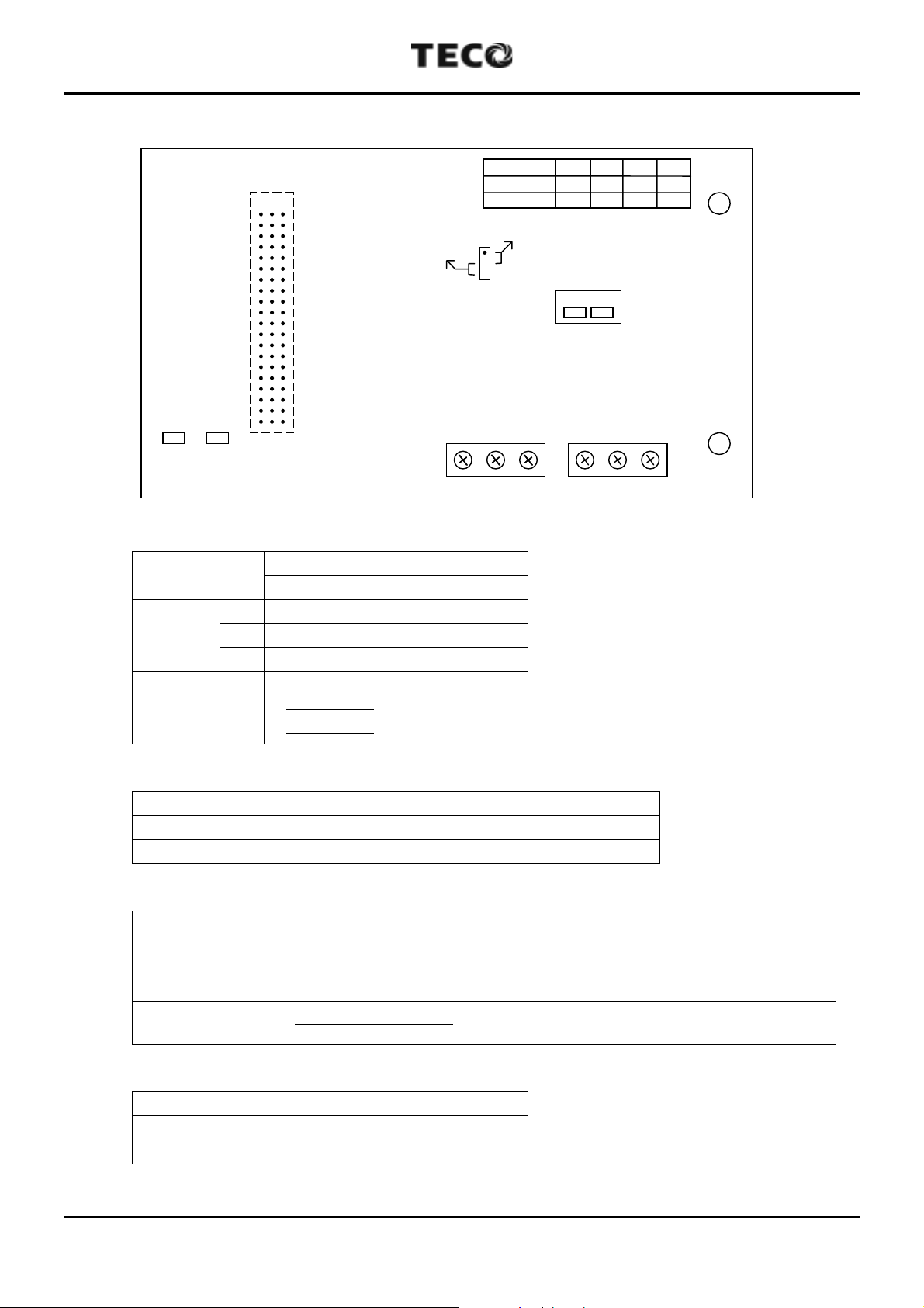
5. Description of Terminal, LED, DIP Switch and Jumper
Receive
(1) Terminal
Terminal
TB1
TB2
CN1
5
LED2LED1
Send
TB1 TB2E12 E34
Function
RS-485 RS-422
1S+ TX+
2S
-
TX
E Shield Shield
3 ------------------- RX+
4 ------------------- RX
-
E ------------------- Shield
JP1
RS-485
RS-422
RS-422
1234
S+ S---
TX+ TX-RX+ RX
SW1
-
(2) LED
LED Description
Receive Flash while data are being received from PLC.
Send Flash while data are being sent from PLC.
(3) DIP Switch (ON : enable terminal resistor, OFF : disable terminal resistor)
DIP
Switch
SW1-1
Control terminal resistor between S+
RS-485 RS-422
and S-.
SW1-2 ----------------------------------
Description
Control terminal resistor between
TX+ and TX -.
Control terminal resistor between
RX+ and RX-.
(4) Jumper
Jumper Description
RS-422 RS-422 Communication Interface.
RS-485 RS-485 Communication Interface.
4/30
Page 6

7300PA Modbus
Application Manual
6. Related parameters for MODBUS communication
(1) Node address (*1)
Sn-23 = 1~31 Inverter Node Address (Default = 1)
(2) Baud rate (*1)
Sn-24 = 00
= 01
= 10
= 11
(3) Parity Check (*1)
Sn-24 = --00 No Parity (Default = --00)
=
(4) Stopping Method while RS485 Communication Fault/Alarm.
Sn-08 = 00
= 10
= 11
--
--
--
--
--
01 Even Parity
= --10 Odd Parity
--
=
11 Reserved
--
--
= 01
--
--
2400 BPS
4800 BPS
9600 BPS
19200 BPS (Default = 11--)
Decelerating to stop by Bn-02 (Default = 00--)
Coasting to stop
Decelerating to stop by Bn-04
Continuous operation
(Can be stopped by STOP Key if Sn-05 =
(5) Time-out Check
Cn-31 = 00.0 s Don’t care
= 0.1 - 25.5 Checked Error (Default = 01.0 s)
(6) Source of Run/Stop command and Frequency reference
---
Sn-08 =
=
=
=
(Default =
*1 The change will be effective in the next start time after turning off the inverter.
0 Frequency reference is from RS-485.
---
1 Frequency reference is from Operator or Terminal.
--0-
--1-
Run/Stop command is from RS-485.
Run/Stop command is from Operator or Terminal.
--
11)
---
0)
5/30
Page 7

7300PA Modbus
Application Manual
7. Connecting inverter with host controller
(1) Operation procedure
A. Turn on the inverter, set the related parameters and turn off the inverter.
B. Turn on the inverter again.
C. Connect inverter and host controller.
D. Host controller sends communication message.
(2) Communication status indication of inverter
While Run/Stop command and/or Frequency reference is from RS-485 (Sn-08), and the
inverter does not receive any message from host controller after power on 1 seconds,
the inverter will display "Call" and flash. This message will disappear while inverter has
received messages from host controller.
While Run/Stop command and/or Frequency reference is from RS-485 (Sn-08), the
time-out detection is enabled (Cn-31 <> 0) and the inverter does not receive any
message from host controller in time specified by Cn-31, the inverter will display
"CPF21".
While Run/Stop command and/or Frequency reference is from RS-485 (Sn-08), the
inverter receives any message with incorrect communication format. (Baud rate, parity,
data bit and stop bit) the inverter will display "CPF22".
Bit 2, 3 of parameter Sn-08 will decide the display format and operation of “CPF21",
“CPF22".
= 11
--
--
--
--
Decelerating to stop by Bn-02 (fault “CPF21”/“CPF22” light up)
Coasting to stop (fault “CPF21”/“CPF22” light up)
Decelerating to stop by Bn-04 (fault “CPF21”/“CPF22” light up)
Continuous operation (alarm “CPF21"/"CPF22" flash)
Sn-08 = 00
= 01
= 10
6/30
Page 8
7300PA Modbus
Application Manual
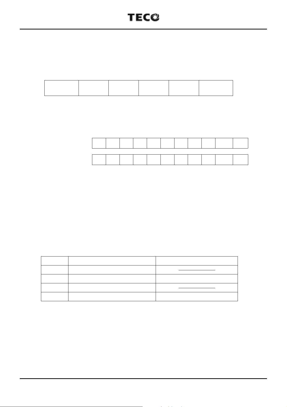
8. Protocol Format
(1) A message of MODBUS RTU mode contains 4 parts: slave address, function code,
data and CRC-16 character. The interval between two messages needs 3.5
characters transferring time.
T1 T2 T3 T4
T1~T4 : 3.5 Characters transferring time at least
(2) Following is the data bit format for MODBUS RTU mode. (LSB will be sent first)
Even/Odd Parity Start 1 2 3 4 5 6 7 8 Parity Stop
No Parity Start 1 2 3 4 5 6 7 8 Stop Stop
(3) Slave Address
Parameter Sn-23 can set the node address of each inverter (1~31). Every slave stand
can receive the message sent from host controller. Only the corresponding one returns
the message to master.
If the slave address of receiving message is 0, all slave stands will execute this
Slave
Address
LSB
Bit0 Bit1 Bit2 Bit3 Bit4 Bit5 Bit6 Bit7 Bit8 Bit9
Function
Code
Data
Character
CRC-16
Character
T1 T2 T3 T4
MSB
Bit10
command and do not return the message to master. This message can only use for
Register 0001H and 0002H.
(4) Function Code
Code Function Note
03H Read Data of Holding Register ------------------06H Write Data to Single Register the Slave Address can be 0
08H Loop Test ------------------10H Write Data to Holding Register the Slave Address can be 0
(5) Data Characters
Detail descriptions will be discussed in "Message Format" section (p.9-12) because it
depends on the function code.
7/30
Page 9

7300PA Modbus
Application Manual
(6) CRC-16 data
CRC-16 Generation Procedure.
A. Load a 16-bit register with FFFFH. Call this the CRC register.
B. Exclusive OR the first 8-bit byte of the message with the low order byte of the 16-bit
CRC registers, putting the result in the CRC register.
C. Shift the CRC register one bit to the right (toward the LSB), zero filling the MSB.
Extract and examine the LSB.
D.If LSB is 0, repeat procedure C (another shift).
If LSB is 1, Exclusive OR the CRC register with the polynomial value A001H.
E. Repeat procedure C, D until eight shifts has been performed.
While this is done, a complete byte will have been processed.
F. Repeat procedure B-E to the following byte of the message until all bytes of the
message is processed.
Now, the value of CRC register is the CRC-16 data.
G. When the CRC is placed into the message, it upper and lower bytes must be
swapped.
(7) Inverter return messages
A. Please refer to the “Message Format” in next page about inverter returning
messages for more detail descriptions.
B. It needs 5ms to return messages after inverter had received normal message from
host controller.
C. In next two cases, inverter does not return any message :
(a) There is any error detected in received data message (parity error, framing error,
overrun error or CRC-16 error).
(b) Slave Address character is different to parameter Sn-36 (Inverter Slave No.).
8/30
Page 10
7300PA Modbus
Application Manual
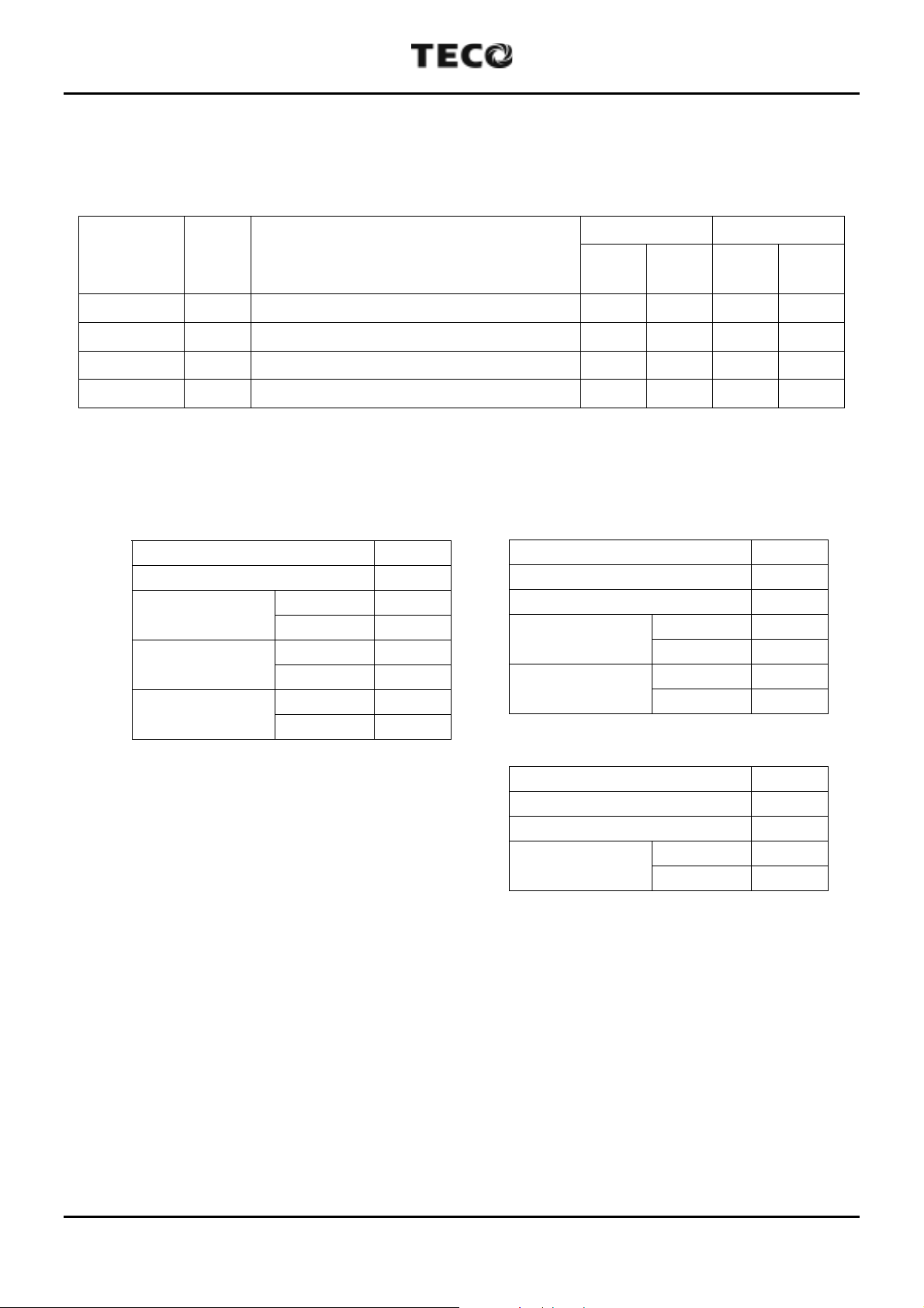
9. Message Format
7300PA supports 4 MODBUS Function codes only.
Table 1 Message Length
Host Query Inverter Return
Function
Code
Function
Byte
(Min.)
Byte
(Max.)
Byte
(Min.)
Byte
(Max.)
Data Read 03H Read Data from Holding Register 8 8 7 37
Data Write 06H Write Data to Single Holding Register 8 8 8 8
Loop Test 08H Loop Test 8 8 8 8
Data Write 10H Write Data to Holding Register 11 41 8 8
(1) Read Command : Read data of Holding Register
Host Query
Slave Address 01H
Function Code 03H
Head Address
(*1)
Access Count
(*2)
CRC-16
High Byte 00H
Low Byte 01H
High Byte 00H
Low Byte 01H
Low Byte D5H
Inverter Return (Normal)
Slave Address 01H
Function Code 03H
Data Byte Count 02H
Data Value
High Byte 00H
Low Byte 00H
CRC-16
Low Byte B8H
High Byte 44H
High Byte CAH
Inverter Return (Error Detected)
Slave Address 01H
80H + Function Code 83H
Error Code (*3) 03H
CRC-16
Low Byte 01H
High Byte 31H
*1 Refer to p.13-23 to see the holding register tag list.
*2 Host controller can read 16 registers at most in each transferring message.
*3 Refer to p.24 to see the error code.
9/30
Page 11

7300PA Modbus
Application Manual
(2) Write Command : Write Data to Single Holding Register
Host Query
Slave Address (*1) 01H
Function Code 06H
Address (*2)
Data Value
CRC-16
High Byte 00H
Low Byte 01H
High Byte 00H
Low Byte 01H
Low Byte 19H
High Byte CAH
Inverter Return (Normal)
Slave Address 01H
Function Code 06H
Address
Data Value
CRC-16
Inverter Return (Error Detected)
Slave Address 01H
80H + Function Code 86H
Error Code (*3) 01H
CRC-16
High Byte 00H
Low Byte 01H
High Byte 00H
Low Byte 01H
Low Byte 19H
High Byte CAH
Low Byte 83H
High Byte A0H
*1 If slave address is 0 (valid for address 0001H and 0002H only), all slave inverters
will execute this command but do not return message to master.
*2 Refer to p.13-23 to see the holding register tag list.
*3 Refer to p.24 to see the error code.
• Parameters modified will not be saved to EEPROM Automatically. We can save
parameters to EEPROM by writing data to address 0900H.
10/30
Page 12

7300PA Modbus
Application Manual
(3) Loop Test Command (test inverter communication status)
Host Query
Slave Address
Function Code
Test Code
Test Data (*1)
CRC-16
*1 The test data is arbitrary.
High Byte
Low Byte 00H
High Byte
Low Byte 55H
Low Byte
High Byte 94H
01H
08H
00H
AAH
5EH
Inverter Return (Normal)
Slave Address
Function Code
Test Code
Test Data
CRC-16
Inverter Return (Error Detected)
Slave Address
80H + Function Code
Error Code (*2)
CRC-16
High Byte
Low Byte
High Byte
Low Byte
Low Byte
High Byte 94H
Low Byte
High Byte C0H
01H
08H
00H
00H
AAH
55H
5EH
01H
88H
01H
87H
*2 Refer to p.24 to see the error code.
11/30
Page 13

7300PA Modbus
Application Manual
(4) Write Holding Register Command (*4)
Host Query
Slave Address (*1) 01H
Function Code 10H
Head address
(*2)
Access Count
(*3)
Data Byte Count (*4) 02H
Data Value
CRC-16
*1 If the slave address of host query message is 0, all slave inverters will execute this
High Byte 00H
Low Byte 01H
High Byte 00H
Low Byte 01H
High Byte 00H
Low Byte 01H
Low Byte 67H
High Byte 41H
Inverter Return (Normal)
Slave Address 01H
Function Code 10H
Head address
Access Count
(*1)
CRC-16
Inverter Return (Error Detected)
Slave Address 01H
80H+Function Code 90H
Error Code (*5) 03H
CRC-16
High Byte 00H
Low Byte 01H
High Byte 00H
Low Byte 01H
Low Byte 50H
High Byte 09H
Low Byte 0CH
High Byte 01H
command but do not return message to master.
*2 Refer to p.13-23 to see the holding register tag list.
*3 Host controller can write 16 registers at most in each transferring message.
*4 Data Byte Count = 2 * Access Count.
*5 Refer to p.24 to see the error code.
• Parameters modified will not be saved to EEPROM Automatically. We can save
parameters to EEPROM by writing data to address 0900H.
12/30
Page 14

7300PA Modbus
Application Manual
10. Holding Register Tag List
(1) Control Data Register (Read / Write)
Address
HEX DEC
0001H 1
0002H 2 Frequency Reference (100/1Hz) p.15
0003H 3 Reserved
0004H 4 Reserved
0005H 5 Reserved
0006H 6 Reserved
0007H 7 Reserved
0008H 8 Reserved
0009H 9
000AH 10 Analog Output Command 1 (255/10V) p.15
000BH 11 Analog Output Command 2 (255/10V) p.15
000CH 12 Reserved
000DH 13 Reserved
000EH 14 Reserved
000FH 15 Reserved
Operation
Signals
Multifunction
Output
Command
Function Description
0 RUN Command
1 REV Command
2 External Fault
3 Fault Reset
4 Multifunction Ref 1
5 Multifunction Ref 2
6 Multifunction Ref 3
7 Multifunction Ref 4
8-15 Reserved
0 Relay Output (R2A-R2C) Output
1 Digital Output (DO1) Output
2 Relay Output (R1A-R1C) Output
3-15 Reserved
Ref.
Page
p.14
p.15
*1 Control Data Register can be used for Salve Address '0' write-in message.
13/30
Page 15

7300PA Modbus
Application Manual
Address
HEX DEC
Function Description
0001H 1 Operation Signals
BIT Function Description
2 (*1) 1 : Run (RUN), 0 : Stop (STOP)
2 (*1) 1 : Reverse Run (REV), 0 : Forward Run (FWD)
2 (*2) External Fault (EB) : Invert output OFF, Fault Output ON
3 Fault Reset (RESET)
4 (*3)
5 (*3)
6 (*3)
7 (*3)
Multifunction Ref. 1
(By Sn-15 setting, Initial setting : multi-step speed ref. 1)
Multifunction Ref. 2
(By Sn-16 setting, Initial setting : multi-step speed ref. 2)
Multifunction Ref. 3
(By Sn-17 setting, Initial setting : jogging ref.)
Multifunction Ref. 4
(By Sn-18 setting, Initial setting : external baseblock)
8-15 Reserved
*1 This register becomes effective by setting Sn-08 (run mode selection 5) to --0-.
*2 External baseblock function is OR operation of command from bit 2 (EB) and command by
inverter external terminal
3
. "Emergency stop" is possible by external terminal 3 even
while inverter is running by MODBUS.
*3 Multifunction Ref. 1-4 are OR operation of command from bit 4-7 and command by inverter
external terminals
5-8
.
14/30
Page 16

7300PA Modbus
Application Manual
Address
HEX DEC
0001H 1 Frequency Reference (100/1Hz)
• This register becomes effective by setting Sn-08 (run mode selection 5) to ---0.
Address
HEX DEC
0009H 9 Multifunction Output Command
BIT Function Description
0 1 : R2A-R2C ON, 0 : R2A-R2C OFF
1 1 : DO1 ON, 0 : DO1 OFF
2 1 : R1A-R1C ON, 0 : R1A-R1C OFF
4-15 Reserved
• These bits become effective by setting Sn-20-22 (Sn-20 for bit 0, Sn-21 for bit 1 and Sn-22 for
bit 2) to 15.
Function Description
Function Description
Address
HEX DEC
000AH 10 Analog Output Command 1 (255/10V)
000BH 11 Analog Output Command 2 (255/10V)
• These registers become effective by setting Sn-26-27 (Sn-26 for register 000A, Sn-27 for
register 000B) to 10.
Function Description
15/30
Page 17

7300PA Modbus
Application Manual
(2) Monitor Data Register (Read Only)
Address
HEX DEC
Function Description
0 Running
1 Reverse Running
2 Inverter Ready
3 Major Fault
0020H 32 Status Signals
4 Reserved
5 Relay Output (R2A-R2C) Output
6 Digital Output (DO1) Output
7 Relay Output (R1A-R1C) Output
8-15 Reserved
Overcurrent or Ground Fault
0
(OC, GF)
1 Overvoltage (OV)
2 Inverter Overload (OL1, OL2)
3 Inverter Overheat (OH)
4 Reserved
5 Reserved
0021H 33 Fault Contents
6 Reserved
7 External Fault (EFxx)
8 Control Circuit Fault (CPFxx)
9 Motor Overload (OL3)
10 Reserved
11 Reserved
12 Power Loss or MC defective (UVx)
13-15 Reserved
0022H 34 Reserved
0023H 35 Frequency Reference (100/1Hz)
0024H 36 Output Frequency (100/1Hz)
0025H 37 Reserved
0026H 38 Reserved
0027H 39 Output Current (10/1A)
0028H 40 Output Voltage (1/1V)
0029H 41 Main Speed (VIN+AIN) A/D Converted Value (1023/10V)
002AH 42 AUX. Speed A/D Converted Value (1023/10V)
0 1 : Terminal 1 is close
1 1 : Terminal 2 is close
2 1 : Terminal 3 is close
3 1 : Terminal 4 is close
002BH 43
Digital Input
Terminal Value
4 1 : Terminal 5 is close
5 1 : Terminal
6 1 : Terminal
7 1 : Terminal
6
7
8
is close
is close
is close
8-15 Reserved
Ref.
Page
p.18
p.18
16/30
Page 18

7300PA Modbus
Application Manual
Address
HEX DEC
002CH 44 Inverter Status
002DH 45
002EH 46 Reserved
002FH 47 Reserved
0030H 48 Reserved
0031H 49 Main Circuit DC Voltage (1/1V)
0032H 50 Reserved
0033H 51 Reserved
0034H 52 Reserved
0035H 53 Reserved
0036H 54 Reserved
0037H 55 Reserved
0038H 56 Reserved
0039H 57 Reserved
003AH 58 Reserved
003BH 59 Reserved
003CH 60 Reserved
003DH 61 Reserved
003EH 62 Reserved
003FH 63 Reserved
Digital Output
Terminal Value
Function Description
0 Running
1 During Zero Speed
2 During Frequency Coincidence
3 Arbitrary Frequency Coincidence
4 Frequency Detection 1
5 Frequency Detection 2
6 Inverter Ready
7 Undervoltage Detecting
8 Output Baseblock
9 Frequency Reference Mode
10 Run Command Mode
11 Overtorque Detection
12 Frequency Reference Missing
13 Reserved
14 Major Fault
15 Reserved
0 1 : R2A-R2C ON
1 1 : DO1-DCOM ON
2 1 : R1A-R1C ON
3-15 Reserved
Ref.
Page
p.19
17/30
Page 19

7300PA Modbus
Application Manual
Address
HEX DEC
Function Description
0020H 32 Status Signals
BIT Function Description
0 1 : Running, 0 : Stop
1 1 : Reverse Run, 0 : Forward Run
2 1 : Inverter Operation Ready (*1)
3 1 : Major Fault (Except CPF00, CPF01)
4 Reserved
5
6
7
Multifunction Output 1 (R2A-R2C)
(By Sn-20 setting. Default setting : during running)
Multifunction Output 2 (DO1-DCOM)
(By Sn-21 setting, Default setting : zero speed)
Multifunction Output 3 (R1A-R1C)
(By Sn-22 setting, Default setting : agreed frequency)
8-15 Reserved
*1 This bit will be set to 1 when the inverter is in the DRIVE mode and there is no alarm, fault or
baseblock.
Address
HEX DEC
0021H 33 Fault Contents
BIT Function Description
0 Overcurrent (OC) or Ground Fault (GF)
1 Overvoltage (OV)
2 Inverter Overload (OL1, OL2)
3 Inverter Overheat (OH)
4-6 Reserved
7 External Fault (EF3, EF5, EF6, EF7, EF8)
Control Circuit Fault (CPF02)
8
EEPROM fault (CPF03)
EEPROM BCC CODE Error (CPF04)
CPU ADC Fault (CPF05)
9 Motor Overload (OL3)
10-11 Reserved
Main circuit low voltage or momentary power loss
12
protection (UV1)
Control circuit low voltage (UV2)
Man circuit soft charge contactor defective (UV3)
13-15 Reserved
Function Description
18/30
Page 20

7300PA Modbus
Application Manual
Address
HEX DEC
002CH 44 Inverter Status
BIT Function Description
0 1 : Running
1 1 : During Zero Speed
1 : During Frequency Coincidence
2
3
4
5
6 1 : Inverter Operation Ready (*2)
7 1 : Undervoltage Detecting
8 1 : Output Baseblock
9
10
11
12 1 : Frequency Reference is Missing
13 Reserved
14 1 : Major Fault (Except CPF00, CPF01)
15 Reserved
Freq. Ref -
(
Cn-22
1 : Arbitrary Frequency Coincidence
Frequency Coincidence and
(Cn-21 - Cn-22) < Output Freq. <
1 : Frequency Detection 1
Output Freq. > Cn-21 (*1)
1 : Frequency Detection 2
Output Freq. < Cn-21 (*1)
0 : Frequency Reference is from RS-485.
1 : Frequency Reference is from Operator or terminal.
0 : RUN/STOP Command is from RS-485.
1 : RUN/STOP Command is from Operator or terminal.
1 : Overtorque Detection
(Detection Level : Cn-26, Detection Time : Cn-27)
Function Description
< Output Freq. <
)
Freq. Ref +
(
Cn-22
(Cn-21 + Cn-22)
)
*1
Cn-22
Output
Frequency
Frequency
Detection 1
*2 This bit will be set to 1 when the inverter is in the DRIVE mode and there is no alarm, fault or
baseblock.
1
0
Cn-21
1
Cn-22
Output
Frequency
Frequency
Detection 2
Cn-21
0
1
0
19/30
Page 21

7300PA Modbus
Application Manual
(3) Inverter Parameter Register (An, Bn : Read/Write, Others : Read Only)
Address Parameter
HEX DEC No. Description Unit
System Parameters Sn
0101H 257 Sn-01 Inverter Capacity Selection
0102H 258 Sn-02 V/f Curve Selection
0103H 259 Sn-03 Operation Status
0104H 260 Sn-04 Operation Mode Select 1
0105H 261 Sn-05 Operation Mode Selection 2
0106H 262 Sn-06 Operation Mode Selection 3
0107H 263 Sn-07 Operation Mode Selection 4
0108H 264 Sn-08 Operation Mode Selection 5
0109H 265 Sn-09 Operation Mode Selection 6
010AH 266 Sn-10 Protective Characteristic Selection 1
010BH 267 Sn-11 Protective Characteristic Selection 2
010CH 268 Sn-12 Protective Characteristic Selection 3
010DH 269 Sn-13 Protective Characteristic Selection 4
010EH 270 Sn-14 Protective Characteristic Selection 5
010FH 271 Sn-15 Terminal
0110H 272 Sn-16 Terminal
0111H 273 Sn-17 Terminal
0112H 274 Sn-18 Terminal
5
6
7
8
Function
Function
Function
Function
0113H 275 Sn-19 Terminal AUX Function
0114H 276 Sn-20 Terminal R2A-R2C Function
0115H 277 Sn-21 Terminal D01 Function
0116H 278 Sn-22 Terminal R1A Function
0117H 279 Sn-23 Inverter station address
0118H 280 Sn-24 RS-485 communication protocol setting
0119H 281 Sn-25 LCD Language displayed selection
011AH 282 Sn-26 Multi-Function Analog Output A01 Function Selection
011BH 283 Sn-27 Multi-Function Analog Output A02 Function Selection
011CH 284
011DH 285
-
-
Reserved
Reserved
011EH 286 Sn-30 Pump Operation Mode Selection
011FH 287 Sn-31 PA-PID Card Relay 2 Control
0120H 288 Sn-32 PA-PID Card Relay 3 Control
0121H 289 Sn-33 PA-PID Card Relay 4 Control
0122H 290 Sn-34 PA-PID Card Relay 5 Control
0123H 291 Sn-35 PA-PID Card Relay 6 Control
0124H 292 Sn-36 PA-PID Card Relay 7 Control
0125H 293 Sn-37 PA-PID Card Relay 8 Control
0126H 294 Sn-38 Parameter copy
Notes
-
-
-
-
-
-
-
-
-
-
-
-
-
-
-
-
-
-
-
-
-
-
-
-
-
-
-
-
-
-
-
-
-
-
-
-
-
-
20/30
Page 22

7300PA Modbus
Application Manual
Address Parameter
HEX DEC No. Description Unit
Control Parameters Cn
0200H 512 Cn-01 Input Voltage 0.1V
0201H 513 Cn-02 Max. Output Frequency 0.1Hz
0202H 514 Cn-03 Max. Output Voltage 0.1V
0203H 515 Cn-04 Max. Voltage Frequency 0.1Hz
0204H 516 Cn-05 Middle Output Frequency 0.1Hz
0205H 517 Cn-06 Voltage At Middle Output Frequency 0.1V
0206H 518 Cn-07 Min Output Frequency 0.1Hz
0207H 519 Cn-08 Voltage At Min. Output Frequency 0.1V
0208H 520 Cn-09 Motor Rated Current 0.1A
0209H 521 Cn-10 DC Injection Braking Starting Frequency 0.1Hz
020AH 522 Cn-11 DC Braking Current 1%
020BH 523 Cn-12 DC Injection Braking Time At Stop 0.1s
020CH 524 Cn-13 DC Injection Braking Time At Start 0.1s
020DH 525 Cn-14 Frequency Command Upper Bound 1%
020EH 526 Cn-15 Frequency Command Lower Bound 1%
020FH 527 Cn-16 Frequency Jump Point 1 0.1Hz
0210H 528 Cn-17 Frequency Jump Point 2 0.1Hz
0211H 529 Cn-18 Frequency Jump Point 3 0.1Hz
0212H 530 Cn-19 Jump Frequency Width 0.1Hz
0213H 531 Cn-20 Digital Operator Display Unit 1
0214H 532 Cn-21 Frequency Agree Detection Level 0.1Hz
0215H 533 Cn-22 Frequency Agree Detection Width 0.1Hz
0216H 534 Cn-23 Carrier Frequency Upper Limit 0.1KHz
0217H 535 Cn-24 Carrier Frequency Lower Limit 0.1KHz
0218H 536 Cn-25 Carrier Frequency proportion Gain 1
0219H 537 Cn-26 Overtorque Detection Level 1%
021AH 538 Cn-27 Overtorque Detection Time 0.1s
021BH 539 Cn-28 Stall Prevention Level During Acceleration 1%
021CH 540
021DH 541 Cn-30 Stall Prevention Level During Running 1%
021EH 542 Cn-31 Communication Fault Detection Time 0.1s
021FH 543 Cn-32 Frequency Detection 1 Level 0.1Hz
0220H 544 Cn-32 Frequency Detection 2 Level 0.1Hz
0221H 545
0222H 546
0223H 547 Cn-36 Number of Auto Restart Attempt 1
0224H 548 Cn-37 Power Loss Ride-through Time 0.1s
0225H 549 Cn-38 Speed Search Detection Level 1%
0226H 550 Cn-39 Speed Search Time 0.1s
0227H 551 Cn-40 Min. Baseblock Time 0.1s
0228H 552 Cn-41 V/F Curve in Speed Search 1%
0229H 553 Cn-42 Voltage Recovery Time 0.1s
022AH 554 Cn-43 PID Integral Upper Bound 1%
-
-
-
Reserved
Reserved
Reserved
-
-
-
Notes
21/30
Page 23

7300PA Modbus
Application Manual
Address Parameter
HEX DEC No. Description Unit
022BH 555 Cn-44 PID Primary Delay Time Constant 0.1s
022CH 556 Cn-45 Energy-Saving Volt. Upper Limit (60Hz) 1%
022DH 557 Cn-46 Energy-Saving Volt. Upper Limit (6Hz) 1%
022EH 558 Cn-47 Energy-Saving Volt. Lower Limit (60Hz) 1%
022FH 559 Cn-48 Energy-Saving Volt. Lower Limit (6Hz) 1%
0230H 560 Cn-49 Tuning Operation Voltage Limit 1%
0231H 561 Cn-50 Tuning Operation Control Cycle 0.1s
0232H 562 Cn-51 Tuning Operation Volt. Step (100% output Volt) 0.10%
0233H 563 Cn-52 Tuning Operation Volt. Step (5% output Volt) 0.10%
0234H 564
0235H 565
0236H 566
0237H 567
0238H 568
0239H 569 Cn-58 Energy-Saving Coefficient K2 (60Hz) 0.01
023AH 570 Cn-59 Energy-Saving Coefficient Reduction ratio (6Hz) 1%
023BH 571 Cn-60 Motor Code
023CH 572
023DH 573 Cn-62 Auto Restart Time Interval 1s
023EH 574 Cn-63 Motor Overheat protection time 1s
Order Parameters On
0300H 768 On-01 Control Status 1
0301H 769 On-02 Control Status 2
0302H 770 On-03 Control Status 3
0303H 771
0304H 772
0305H 773
0306H 774 On-07 Hunting Prevention gain 0.01
0307H 775 On-08 Hunting Prevention limit 1%
0308H 776 On-09 Effective current detection filter time constant 1(3.5ms)
0309H 777
030AH 778 On-11 ON-DELAY TIME 1(0.25µs)
030BH 779 On-12 ON-DELAY Compensated value 1(0.25µs)
030CH 780
030DH 781
030EH 782 On-15 Power detection filter changing width 1%
030FH 783 On-16 Power detection filter time constant 1(7ms)
0310H 784 On-17 Motor phase to phase resistance 0.001Ω
0311H 785 On-18 Torque Compensation of care loss 1W
0312H 786 On-19 Torque Compensation limit 1V
0313H 787 On-20 Motor Constant R1 0.001Ω *1
0314H 788 On-21 Motor Constant R2 0.001Ω *1
0315H 789 On-22 Motor Constant L 0.001mH *1
0316H 790 On-23 Motor Constant Rm 0.001mΩ/ω *1
0317H 791 On-24 Motor Constant Lm 0.01mH *1
-
-
-
-
-
-
-
-
-
-
-
-
Reserved
Reserved
Reserved
Reserved
Reserved
Reserved
Reserved
Reserved
Reserved
Reserved
Reserved
Reserved
-
-
-
-
-
-
-
-
-
-
-
-
-
-
-
-
Notes
22/30
Page 24

7300PA Modbus
Application Manual
Address Parameter
HEX DEC No. Description Unit
Frequency Command An
0400H 1024 An-01 Frequency Command 1 0.01Hz *2
0401H 1025 An-02 Frequency Command 2 0.01Hz *2
0402H 1026 An-03 Frequency Command 3 0.01Hz *2
0403H 1027 An-04 Frequency Command 4 0.01Hz *2
0404H 1028 An-05 Frequency Command 5 0.01Hz *2
0405H 1029 An-06 Frequency Command 6 0.01Hz *2
0406H 1030 An-07 Frequency Command 7 0.01Hz *2
0407H 1031 An-08 Frequency Command 8 0.01Hz *2
0408H 1032 An-09 Jog Frequency Command 0.01Hz *2
Parameters Groups Can Be Changed during Running Bn
0500H 1280 Bn-01 Acceleration Time 1 0.1s *2
0501H 1281 Bn-02 Deceleration Time 1 0.1s *2
0502H 1282 Bn-03 Acceleration Time 2 0.1s *2
0503H 1283 Bn-04 Deceleration Time 2 0.1s *2
0504H 1284 Bn-05 Analog Frequency Cmd. Gain 0.10% *2
0505H 1285 Bn-06 Analog Frequency Cmd. Bias 0.10% *2
0506H 1286 Bn-07 Auto torque Boost Gain 0.1 *2
0507H 1287 Bn-08 Multi-Function Analog Output A01 Bias 0% *2
0508H 1288 Bn-09 Multi-Function Analog Output A02 Bias 0.10% *2
0509H 1289 Bn-10 Monitor No. After power ON
050AH 1290 Bn-11 Multi-Function Analog Output A01 Gain 1% *2
050BH 1291 Bn-12 Multi-Function Analog Output A02 Gain 0.01 *2
050CH 1292 Bn-13 PID Detection Gain 0.01 *2
050DH 1293 Bn-14 PID Proportional Gain 10% *2
050EH 1294 Bn-15 PID Integral Gain 0.1s *2
050FH 1295 Bn-16 PID Differential Time 0.01s *2
0510H 1296 Bn-17 PID Bias 1% *2
0511H 1297 Bn-18 PID sleep Frequency 0.01Hz *2
0512H 1298 Bn-19 PID sleep/Wake-up Delay Time 0.1s *2
0513H 1299 Bn-20 PID Wake Up Frequency 0.01Hz *2
0514H 1300 Bn-21 PID Detected Value Display Bias 0.001 *2
0515H 1301 Bn-22 PID Detected Value Display Gain 0.001 *2
0516H 1302 Bn-23 F req. Command Upper-Bound Delay Time 1s *2
0517H 1303 Bn-24 F req. Command Lower-Bound Delay Time 1s *2
0518H 1304 Bn-25 MC ON/OFF Delay Time 0.01s *2
0519H 1305 Bn-26 Pump ON/OFF Detection Level 0.1% *2
Enter Command
900H 2304 Save An, Bn, Sn and Cn to EEPROM.
-
-
Notes
*2
*3
*1 These parameters can not be saved to EEPROM.
*2 These parameters can be written in DRV mode or PRG mode.
*3 Writing data 0000H to this address in PRG mode can save parameter (except On-20 - 24) to
EEPROM.
• All parameters can be read in PRG mode or DRV mode, and parameters without note *1 can
be written in PRG mode only.
23/30
Page 25

7300PA Modbus
Application Manual
11. Error Code
Code Description Possible Cause
00H CRC Code Error CRC Word (High or Low Byte) Error
01H Function Code Error Function code is not 03H, 06H, 08H or 10H.
02H Register Address Error
03H Access Count Error
21H Register Write Error
22H Data Value Error Data value is out of range in writing message.
Not Response UART Error Parity, Overrun, Frame error.
Not Response Data Format Error
Register address is not in the range that can be
accessed.
The Access Count is more than 16.
"Access Count" in writing command (10H) does
not match the amount of actual data.
Write Cn ,Sn or On parameter during DRIVE
mode
Data string is not correct. (Incomplete Message,
"Data Byte Count" in writing command (10H)
does not match the amount of actual data.)
24/30
Page 26

7300PA Modbus
Application Manual
12. Example of RS-485 Communication Application
Host Controller can control the inverter 7300PA via RS-485 serial communication and let the
inverter operating as following
Output
Frequency (Hz)
60
30
FWD
-30
REV
Digital Output
DO1-DCOM
ON
OFF
Digital Output
R1A-R1C
Step 1
ON
OFF
Step 2 Step 3 Step 4
(1) Run 7300PA forward with 60Hz. Set DO1-DCOM.
(2) Run 7300PA forward with 30Hz. Clear DO1-DCOM. Set R1A-R1C.
(3) Run 7300PA reverse with 30Hz. Set R1A-R1C.
(4) Stop 7300PA. Set R1A-R1C.
25/30
Page 27

7300PA Modbus
Application Manual
(1) Set inverter parameters
Sn-23 = 1 (Inverter Slave Address), Sn-24
Cn-31 = 0.0s (Disable time-out check)
Sn-08 = 1100
--
(11
(
: Continue Running while RS-485 communication fault occurs)
--
00 : Run/Stop and frequency reference from RS-485)
Sn-21 = 0F (DO1-DCOM Output Reserved), Sn-22 = 0F (R1A-R1C Output Reserved)
(2) Turn off the inverter and turn it on again (For Sn-23 and Sn-24 are modified). and
program host controller to operate in step 1-4 and desired operation can be done by
inverter.
26/30
Page 28

7300PA Modbus
Application Manual
Step 1 : Run 7300PA forward with 60Hz. Set DO1-DCOM.
Host Query
Slave Address 01H
Function Code 10H
Head Address
Access Count
High Byte 00H
Low Byte 01H
High Byte 00H
Low Byte 09H
Data Byte Count 12H
Data Value 1
Data Value 2
Data Value 3
Data Value 4
Data Value 5
Data Value 6
Data Value 7
Data Value 8
Data Value 9
CRC-16
High Byte 00H
Low Byte 01H
High Byte 17H
Low Byte 70H
High Byte 00H
Low Byte 00H
High Byte 00H
Low Byte 00H
High Byte 00H
Low Byte 00H
High Byte 00H
Low Byte 00H
High Byte 00H
Low Byte 00H
High Byte 00H
Low Byte 00H
High Byte 00H
Low Byte 02H
Low Byte B1H
High Byte 2BH
Inverter Return
Slave Address 01H
Function Code 10H
Head Address
Access Count
CRC-16
High Byte 00H
Low Byte 01H
High Byte 00H
Low Byte 09H
Low Byte 51H
High Byte CFH
Data Value 1 of Address 0001H = 0001H : Run 7300PA Forward.
Data Value 2 of Address 0002H = 1770H : Speed Reference 60.00Hz.
Data Value 9 of Address 0009H = 0002H : Set DO1-DCOM.
• When Inverter received this message , it will start, accelerate to 60Hz in forward direction
and set digital output terminal DO1-DCOM.
27/30
Page 29

7300PA Modbus
Application Manual
Step 2 : Run 7300PA forward with 50% Speed. Clear DO1-DCOM. Set RA-RB-RC.
Host Query
Slave Address 01H
Function Code 10H
Head Address
Access Count
High Byte 00H
Low Byte 01H
High Byte 00H
Low Byte 09H
Data Byte Count 12H
Data Value 1
Data Value 2
Data Value 3
Data Value 4
Data Value 5
Data Value 6
Data Value 7
Data Value 8
Data Value 9
CRC-16
High Byte 00H
Low Byte 01H
High Byte 0BH
Low Byte B8H
High Byte 00H
Low Byte 00H
High Byte 00H
Low Byte 00H
High Byte 00H
Low Byte 00H
High Byte 00H
Low Byte 00H
High Byte 00H
Low Byte 00H
High Byte 00H
Low Byte 00H
High Byte 00H
Low Byte 04H
Low Byte F1H
High Byte B6H
Inverter Return
Slave Address 01H
Function Code 10H
Head Address
Access Count
CRC-16
High Byte 00H
Low Byte 01H
High Byte 00H
Low Byte 09H
Low Byte 51H
High Byte CFH
Data Value 1 of Address 0001H = 0001H : Run 7300PA Forward.
Data Value 2 of Address 0002H = 0BB8H : Speed Reference 30.00Hz.
Data Value 9 of Address 0009H = 0004H : Set R1A-R1C. Clear DO1-DCOM.
• When Inverter received this message, it will decelerate to 30.00Hz in forward direction,
clear the digital output terminal DO1-DCOM and set the digital output R1A-R1C.
28/30
Page 30

7300PA Modbus
Application Manual
Step 3 : Run 7300PA reverse with 50% Speed. Set RA-RB-RC.
Host Query
Slave Address 01H
Function Code 10H
Head Address
Access Count
High Byte 00H
Low Byte 01H
High Byte 00H
Low Byte 09H
Data Byte Count 12H
Data Value 1
Data Value 2
Data Value 3
Data Value 4
Data Value 5
Data Value 6
Data Value 7
Data Value 8
Data Value 9
CRC-16
High Byte 00H
Low Byte 03H
High Byte 0BH
Low Byte B8H
High Byte 00H
Low Byte 00H
High Byte 00H
Low Byte 00H
High Byte 00H
Low Byte 00H
High Byte 00H
Low Byte 00H
High Byte 00H
Low Byte 00H
High Byte 00H
Low Byte 00H
High Byte 00H
Low Byte 04H
Low Byte 50H
High Byte D6H
Inverter Return
Slave Address 01H
Function Code 10H
Head Address
Access Count
CRC-16
High Byte 00H
Low Byte 01H
High Byte 00H
Low Byte 09H
Low Byte 51H
High Byte CFH
Data Value 1 of Address 0001 = 0003H : Run 7300PA Reverse.
Data Value 2 of Address 0002 = 0BB8H : Speed Reference 30.00Hz
Data Value 9 of Address 0009 = 0004H : Set R1A-R1C.
• When Inverter received this message, it will run at 30.00 Hz in reverse direction, clear
the digital output terminal DO1-DCOM and set the digital output R1A-R1C.
29/30
Page 31

7300PA Modbus
Application Manual
Step 4 : Stop 7300PA. Set R1A-R1C.
Host Query
Slave Address 01H
Function Code 10H
Head Address
Access Count
High Byte 00H
Low Byte 01H
High Byte 00H
Low Byte 01H
Data Byte Count 02H
Data Value 1
CRC-16
High Byte 00H
Low Byte 00H
Low Byte A7H
High Byte 81H
Head Address
Access Count
CRC-16
Inverter Return
Slave Address 01H
Function Code 10H
High Byte 00H
Low Byte 01H
High Byte 00H
Low Byte 01H
Low Byte 50H
High Byte 09H
Data Value1 of Address 0000H = 0000H : Stop 7300PA.
• When inverter received this message, it will stop and decelerate to zero speed, digital
output terminal DO1-DCOM and R1A-R1C do not change their status.
30/30
 Loading...