

Page 1

7300CV MODBUS COMMUNICATION PROTOCOL
File No. :PC-CV-08
Version : 1.A
Page :
1/34
7300CV MODBUS
USER’S MANUAL
COMMUNICATION INTERFACE
Page 2

7300CV MODBUS COMMUNICATION PROTOCOL
File No. :PC-CV-08
Version : 1.A
Page :
2/34
1. Communication Data Frame
7300CV series inverter can be communication controlled by the PC or other controller with the
communication protocol, Modbus ASCII Mode & Mode RTU, RS485 or RS232.
Frame length maximum 80 bytes
1.1 Hardware installation
Slave 7300CV
Station 01
Slave 7300CV
Station 02
Slave 7300CV
Station 03
Slave 7300CV
Station FE
Controller
(PLC / HMI or
PC )
Option Card Option Card Option Card Option Card
RS-485
Interface
RSA RSB RSA RSB RSA RSB
RSA RSB
Response
Request
** The network is terminated at each end with an external terminating resistor (120 ohm, 1/4 watt).
1.2 Data format frame FOR ASCII MODE
STX(3AH) Start Bit = 3AH
Address Hi
Address Lo
Communication Address(Station):
2-digit ASCII Code
Function Hi
Function Lo
Function Code (command):
2-digit ASCII Code
Command Start Address
Command Start Address
Command Start Address
Command Start Address
Command Start byte:
4-digit ASCII Code
Data length
Data length
Data length
Data length
The length of the command:
4-digit ASCII Code
LRC Check Hi
LRC Check Lo
LRC Check Code:
2-digit ASCII Code
END Hi
END Lo
End Byte:
END Hi=CR(0DH),END Li = LF(0AH)
Data format frame FOR RTU MODE
MASTER (PLC etc.) send request to SLAVE, whereas SLAVE response to MASTER. The signal
receiving is illustrated here.
120Ω
1/4w
120Ω
1/4w
Page 3

7300CV MODBUS COMMUNICATION PROTOCOL
File No. :PC-CV-08
Version : 1.A
Page :
3/34
The data length is varied with the command (Function).
SLAVE Address
Function Code
DATA
CRC CHECK
Signal Interval
** The interval should be maintained at 10ms between command signal and request
1.3 SLAVE Address
00H : Broadcast to all the drivers
01H : to the No. 01 Driver
0FH : to the No.15 Driver
10H : to the No.16 Driver
and so on...., Max to No. 254(FEH)
1.4 Function Code
03H : Read the register contents
06H : Write a WORD to register
08H : Loop test
10H : Write several data to register (complex number register write)
2.CMS (Checksum and time-out definition)
2.1 LRC
ex. ADDRESS 01H
FUNCTION 03H
COMMAND 01H
00H
DATA LENGTH 0AH
-----------------------
0FH------------ true complement
Checksum = F1H
CS(H) = 46H (ASCII)
CS(L) = 31H (ASCII)
2.2 CRC CHECK :
CRC check code is from Slave Address to end of the data. The calculation method is illustrated as follow:
(1) Load a 16-bit register with FFFF hex (all's 1). Call this the CRC register.
Page 4

7300CV MODBUS COMMUNICATION PROTOCOL
File No. :PC-CV-08
Version : 1.A
Page :
4/34
(2) Exclusive OR the first 8-bit byte of the message with the low-order byte of the 16-bit CRC
register, putting the result in the CRC register.
(3) Shift the CRC register one bit to the right (toward the LSB), Zero-filling the MSB, Extract and
examines the LSB.
(4) (If the LSB was 0): Repeat Steps (3)(another shift).(If the LSB was 1): Exclusive OR the CRC
register with the polynomial value A001 hex (1010 0000 0000 0001).
(5) Repeat Steps (3) and (4) until 8 shifts been performed. When this is done, a complete 8-bit byte
will be processed.
(6) Repeat Steps (2) through (5) for next 8-bit byte of the message, Continue doing this until all
bytes have been processed. The final content of the CRC register is the CRC value. Placing the
CRC into the message: When the 16-bit CRC (2 8-bit bytes) is transmitted in the message, the
low-order byte will be transmitted first, followed by the high-order byte, For example, if the
CRC value is 1241 hex, the CRC-16 Upper put the 41h, the CRC-16 Lower put the 12h
z CRC calculation application program
UWORD ch_sum ( UBYTE long , UBYTE *rxdbuff ) {
BYTE i = 0;
UWORD wkg = 0xFFFF;
while ( long-- ) {
wkg ^= rxdbuff++;
for ( i = 0 ; i < 8; i++ ) {
if ( wkg & 0x0001 ) {
wkg = ( wkg >> 1 ) ^ 0xa001;
}
else {
wkg = wkg >> 1;
}
}
}
return( wkg );
}
Page 5

7300CV MODBUS COMMUNICATION PROTOCOL
File No. :PC-CV-08
Version : 1.A
Page :
5/34
2.3 TIME-OUT (400ms) & RETRY (max. : 2 times)
PC-LINK S 400ms
PC-LINK S 400ms
PC-LINK S
(When INV(PLC) time-out or detect checksum error, or INV(PLC) response error code = checksum error,
PC-LINK retry maximum two times, and if two times after still error,
then display “ERR6”)
Page 6

7300CV MODBUS COMMUNICATION PROTOCOL
File No. :PC-CV-08
Version : 1.A
Page :
6/34
3.Command START ADDRESS
Function Description
Command
Start Address
Data length
(WORD)
Ladder page1 read 200H 0AH
Ladder page2 read 20AH 0AH
Ladder page3 read 214H 0AH
Ladder page4 read 21EH 0AH
Ladder page5 read 228H 0AH
Timer1 Function read 264H 05H
Timer2 Function read 269H 05H
Timer3 Function read 26EH 05H
Timer4 Function read 273H 05H
Timer5 Function read 278H 05H
Timer6 Function read 27DH 05H
Timer7 Function read 282H 05H
Timer8 Function read 287H 05H
Counter1 Function read 28CH 04H
Counter2 Function read 290H 04H
Counter3 Function read 294H 04H
Counter4 Function read 298H 04H
Encoder1 Function read 2ACH 05H
Encoder2 Function read 2B1H 05H
Encoder3 Function read 2B6H 05H
Encoder4 Function read 2BBH 05H
Analog1 Function read 2C0H 03H
Analog2 Function read 2C3H 03H
Analog3 Function read 2C6H 03H
Analog4 Function read 2C9H 03H
Control function read 2CCH 06H
Contro2 function read 2D2H 06H
Contro3 function read 2D8H 06H
Contro4 function read 2DEH 06H
Contro5 function read 2E4H 06H
Contro6 function read 2EAH 06H
Contro7 function read 2F0H 06H
Contro8 function read 2F6H 06H
03
All Coil status read 2FCH~303H 08H
Page 7

7300CV MODBUS COMMUNICATION PROTOCOL
File No. :PC-CV-08
Version : 1.A
Page :
7/34
Function Description
Command
Start Address
Data length
(WORD)
Ladder page1 write 200H 0AH
Ladder page2 write 20AH 0AH
Ladder page3 write 214H 0AH
Ladder page4 write 21EH 0AH
Ladder page5 write 228H 0AH
Timer1 Function write 264H 04H
Timer2 Function write 269H 04H
Timer3 Function write 26EH 04H
Timer4 Function write 273H 04H
Timer5 Function write 278H 04H
Timer6 Function write 27DH 04H
Timer7 Function write 282H 04H
Timer8 Function write 287H 04H
Counter1 Function write 28CH 03H
Counter2 Function write 290H 03H
Counter3 Function write 294H 03H
Counter4 Function write 298H 03H
Encoder1 Function write 2ACH 04H
Encoder2 Function write 2B1H 04H
Encoder3 Function write 2B6H 04H
Encoder4 Function write 2BBH 04H
Analog1 Function write 2C0H 03H
Analog2 Function write 2C3H 03H
Analog3 Function write 2C6H 03H
Analog4 Function write 2C9H 03H
Control function write 2CCH 06H
Contro2 function write 2D2H 06H
Contro3 function write 2D8H 06H
Contro4 function write 2DEH 06H
Contro5 function write 2E4H 06H
Contro6 function write 2EAH 06H
Contro7 function write 2F0H 06H
10
Contro8 function write 2F6H 06H
06 Coil status write 2FCH 01H
Page 8

7300CV MODBUS COMMUNICATION PROTOCOL
File No. :PC-CV-08
Version : 1.A
Page :
8/34
Function Description
Command
Start Address
Data length
(WORD)
RUN&Stop(PLC) 330H 1
All memory clear
(Clear Plc Memory)
331H 1
06
PASSWORD 332H 1
Note: ‘Write Ladder page write’ and ‘Clear all memory’ are not available under PLC running
mode.
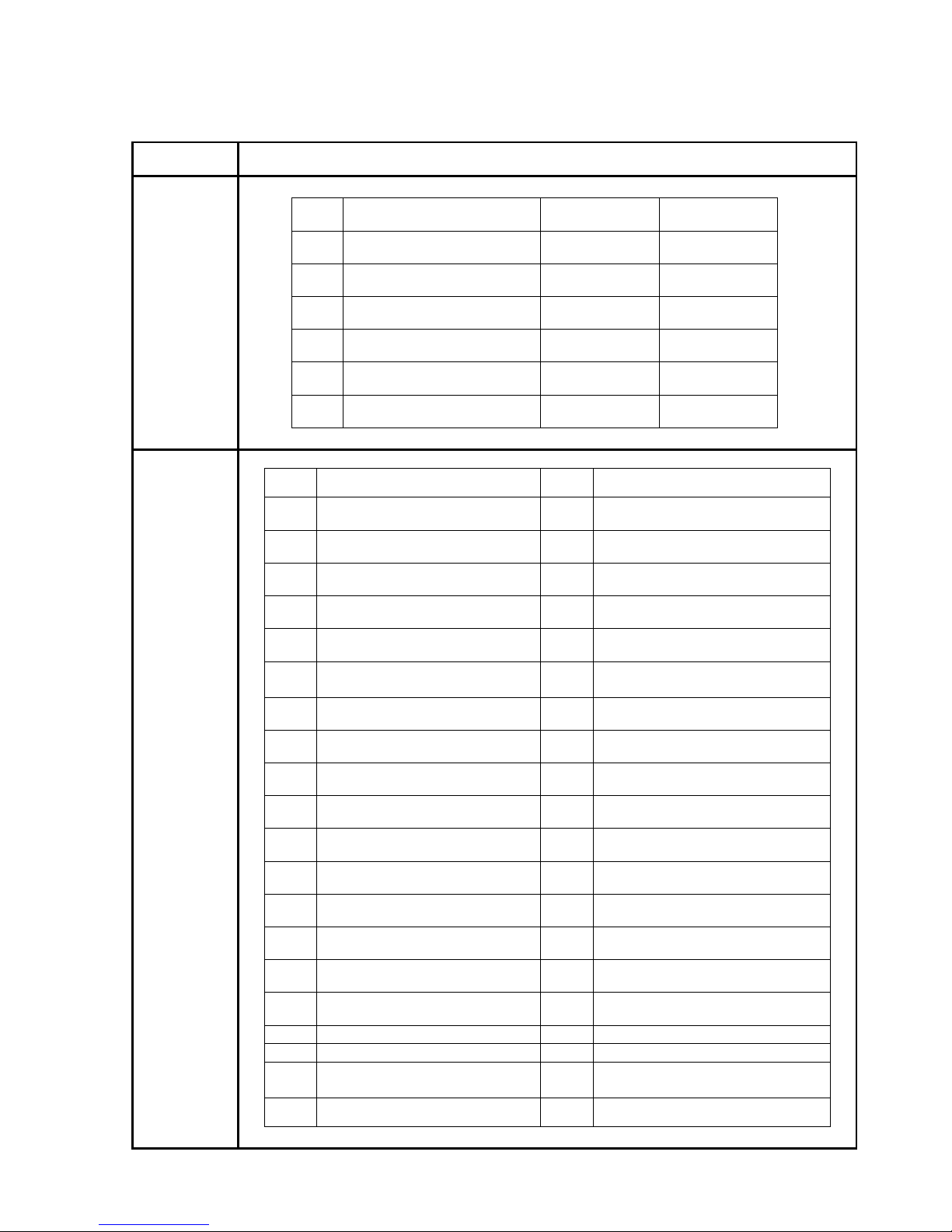
4.Error code
ASCII Mode RTU Mode
STX ‘:’ SLAVE Address 02H
‘0’ Function 83H
Address
‘1’ Exception code 52H
‘8’ High C0H
Function
‘6’
CRC-16
Low CDH
‘5’ Exception
code
‘1’
‘2’
LRC Check
‘8’
‘CR’
END
‘LF’
Under communication linking, the driver responses the Exception Code and send Function Code AND
80H to main system if there is error happened.
Error
Code
Description
51
Function Code Error
52
Address Error
53
Data Amount Error
54
Data Over Range
55 Writing Mode Error
Page 9

7300CV MODBUS COMMUNICATION PROTOCOL
File No. :PC-CV-08
Version : 1.A
Page :
9/34
5.Command Start Address description
5.1 Ladder(* )page read
ASCII Mode
PC Æ INV(PLC) INV(PLC)ÆPC
3AH STX 3AH STX
30H 30H
31H
Address
31H
Address
30H 30H
33H
Function Code
33H
Function Code
30H 31H
32H 34H
Data length
(Byte)
30H
30H
*Register Number
Send out the data from 200H~209H,
total 40 Byte
30H ?
30H ?
CHECK
SUM,
30H 0DH END
41H
Data Length
0AH END
?
?
CHECK SUM,
0DH END
0AH END
RTU Mode
PC Æ INV(PLC) INV(PLC)ÆPC
01H Address
01H Address
03H Function Code
03H Function Code
02H
14H Data length
00H
*Register Number
00H
Sent out the data from 200H~209H,
total 20 Byte
0AH
Data Length
? CRC High Byte
CRC High Byte
? CRC Low Byte
CRC Low Byte
Page 10

7300CV MODBUS COMMUNICATION PROTOCOL
File No. :PC-CV-08
Version : 1.A
Page :
10/34
5.2 Function block read
5.2.1 Timer function block read
ASCII Mode
PC ÆINV(PLC) INV(PLC)ÆPC
3AH STX 3AH STX
30H 30H
31H
Address
31H
Address
30H 30H
33H
Function Code
33H
Function Code
30H 30H
32H 41H
Data length
(Byte)
36H
34H
*Register Number
*Send out the data from
264H~268H, total 20 Byte
30H ?
30H ?
CHECK
SUM,
30H 0DH END
35H
Data Length
0AH END
?
?
CHECK SUM,
0DH END
0AH END
RTU Mode
PC Æ INV(PLC) INV(PLC)ÆPC
01H Address
01H Address
03H Function Code
03H Function Code
02H
0AH Data length
64H
*Register Number
00H
*Send out the data from 264H~268H,
total 10 Byte
05H
Data Length
? CRC High Byte
CRC High Byte
? CRC Low Byte
CRC Low Byte
Page 11

7300CV MODBUS COMMUNICATION PROTOCOL
File No. :PC-CV-08
Version : 1.A
Page :
11/34
5.2.2 Counter function block read
ASCII Mode
PC ÆINV(PLC) INV(PLC) ÆPC
3AH STX 3AH STX
30H 30H
31H
Address
31H
Address
30H 30H
33H
Function Code
33H
Function Code
30H 30H
32H 38H
Data Length
(Byte)
38H
43H
*Register Number
*send out the data from
28CH~28FH, total 16 Byte
30H ?
30H ?
CHECK SUM
30H 0DH END
34H
Data Length
0AH END
?
?
CHECK SUM
0DH END
0AH END
RTU Mode
PC Æ INV(PLC) INV(PLC)ÆPC
01H Address
01H Address
03H Function Code
03H Function Code
02H
08H Data length
8CH
*Register Number
00H
*Send out the data from 28CH~28FH,
total 8 Byte
04H
Data Length
? CRC High Byte
CRC High Byte
? CRC Low Byte
CRC Low Byte
Page 12
7300CV MODBUS COMMUNICATION PROTOCOL
File No. :PC-CV-08
Version : 1.A
Page :
12/34
5.2.3 Encoder function block read
ASCII Mode
PC ÆINV(PLC) INV(PLC) ÆPC
3AH STX 3AH STX
30H 30H
31H
Address
31H
Address
30H 30H
33H
Function Code
33H
Function Code
30H 30H
32H 41H
Data Length
(Byte)
41H
43H
*Register Number
*Send out the data from
2ACH~2B0H, total 20 Byte
30H ?
30H ?
CHECK
SUM,
30H 0DH END
35H
Data Length
0AH END
?
?
CHECK SUM
0DH END
0AH END
RTU Mode
PC Æ INV(PLC) INV(PLC)ÆPC
01H Address
01H Address
03H Function Code
03H Function Code
02H
0AH Data length
ACH
*Register Number
00H
*Send out the data from
2ACH~2B0H, total 10 Byte
05H
Data Length
? CRC High Byte
CRC High Byte
? CRC Low Byte
CRC Low Byte
Page 13

7300CV MODBUS COMMUNICATION PROTOCOL
File No. :PC-CV-08
Version : 1.A
Page :
13/34
5.2.4 Analog function block read
ASCII Mode
PC Æ INV(PLC) INV(PLC) ÆPC
3AH STX 3AH STX
30H 30H
31H
Address
31H
Address
30H 30H
33H
Function Code
33H
Function Code
30H 30H
32H 36H
Data Length
(Byte)
43H
30H
*Register Number
*Send out the data from
2C0H~2C2H, total 12 Byte
30H ?
30H ?
CHECK
SUM,
30H 0DH END
33H
Data Length
0AH END
?
?
CHECK SUM
0DH END
0AH END
RTU Mode
PC Æ INV(PLC) INV(PLC)ÆPC
01H Address
01H Address
03H Function Code
03H Function Code
02H
06H Data length
C0H
*Register Number
00H
**Send out the data from
2C0H~2C2H, total 6 Byte
03H
Data Length
? CRC High Byte
? CRC High Byte
? CRC Low Byte
? CRC Low Byte
Page 14

7300CV MODBUS COMMUNICATION PROTOCOL
File No. :PC-CV-08
Version : 1.A
Page :
14/34
5.2.5 Control function block read
ASCII Mode
PCÆ INV(PLC) INV(PLC) ÆPC
3AH STX 3AH STX
30H 30H
31H
Address
31H
Address
30H 30H
33H
Function Code
33H
Function Code
30H 30H
32H 43H
Data Length
(Byte)
43H
43H
*Register Number
*Send out the data from
2CCH~2D1H, total 24 Byte
30H ?
30H ?
CHECK SUM
30H 0DH END
36H
Data Length
0AH END
?
?
CHECK SUM
0DH END
0AH END
RTU Mode
PC Æ INV(PLC) INV(PLC)ÆPC
01H Address
01H Address
03H Function Code
03H Function Code
02H
0CH Data length
CCH
*Register Number
00H
**Send out the data from
2CCH~2D1H, total 12 Byte
06H
Data Length
? CRC High Byte
CRC High Byte
? CRC Low Byte
CRC Low Byte
Page 15

7300CV MODBUS COMMUNICATION PROTOCOL
File No. :PC-CV-08
Version : 1.A
Page :
15/34
5.2.6 Coil status read
ASCII Mode
PC ÆINV(PLC) INV(PLC) ÆPC
3AH STX 3AH STX
30H 30H
31H
Address
31H
Address
30H 30H
33H
Function Code
33H
Function Code
30H 31H
32H 30H
Data Length
(Byte)
46H
43H
*Register Number
*Send out the data from
2FCH~303H, total 32 Byte
30H ?
30H ?
CHECK SUM
30H 0DH END
38H
Data Length
0AH END
?
?
CHECK SUM
0DH END
0AH END
RTU Mode
PC Æ INV(PLC) INV(PLC)ÆPC
01H Address
01H Address
03H Function Code
03H Function Code
02H
10H Data length
FCH
*Register Number
00H
*Send out the data from
2FCH~303H, total 16 Byte
08H
Data Length
? CRC High Byte
CRC High Byte
? CRC Low Byte
CRC Low Byte
Page 16
7300CV MODBUS COMMUNICATION PROTOCOL
File No. :PC-CV-08
Version : 1.A
Page :
16/34
6.3 Ladder page write
ASCII Mode
PC Æ INV(PLC) INV(PLC) ÆPC
3AH STX
3AH STX
30H
30H
31H
Address
31H
Address
31H
30H
30H
Function Code
33H
Function Code
30H
30H
32H
32H
30H
30H
30H
*Register Number
30H
*Register
Number
30H
30H
30H
30H
30H
30H
41H
Data Length
(Byte)
41H
Data Length
31H
?
34H
DATA Number
?
CHECK
SUM
0DH END
*Send out the data from
200H~209H, total 40 Byte
0AH END
?
?
CHECK SUM
0DH END
0AH END
RTU Mode
PC Æ INV(PLC) INV(PLC)ÆPC
01H Address
01H Address
10H Function Code
03H Function Code
02H
02H
00H
* Register Code
00H
* Register Code
00H
00H
0AH
Data Length
0AH
Data Length
14H
DATA Number
? CRC High Byte
? CRC Low Byte*end out the data from 200H~209H,
total 20 Byte
? CRC High Byte
? CRC Low Byte
Page 17

7300CV MODBUS COMMUNICATION PROTOCOL
File No. :PC-CV-08
Version : 1.A
Page :
17/34
6.4 Function block write
6.4.1 Timer function block write
ASCII Mode
PC ÆINV(PLC) INV(PLC) ÆPC
3AH STX
3AH STX
30H
30H
31H
Address
31H
Address
31H
31H
30H
Function Code
30H
Function Code
30H
30H
32H
32H
36H
36H
34H
*Register Number
34H
*Register
Number
30H
30H
30H
30H
30H
30H
34H
Data Length
(Byte)
34H
Data Length
30H
?
38H
DATA Number
?
CHECK
SUM
0DH END
0AH END
*Send out the data from
264H~267H, total 16 Byte
?
?
CHECK SUM
0DH END
0AH END
RTU Mode
PC Æ INV(PLC) INV(PLC)ÆPC
01H Address
01H Address
10H Function Code
10H Function Code
02H
02H
64H
* Register Code
64H
* Register Code
00H
00H
04H
Data Length
04H
Data Length
08H
DATA Number
? CRC High Byte
? CRC Low Byte*Send out the data from 264H~267H,
total 8 Byte
? CRC High Byte
? CRC Low Byte
Page 18

7300CV MODBUS COMMUNICATION PROTOCOL
File No. :PC-CV-08
Version : 1.A
Page :
18/34
6.4.2 Counter function block write
ASCII Mode
PC Æ INV(PLC) INV(PLC) ÆPC
3AH STX
3AH STX
30H
30H
31H
Address
31H
Address
31H
30H
30H
Function Code
33H
Function Code
30H
30H
32H
32H
38H
38H
43H
*Register Number
43H
*Register
Number
30H
30H
30H
30H
30H
30H
33H
Data Length
(Byte)
33H
Data Length
30H
?
36H
DATA Number
?
CHECK
SUM
0DH END
0AH END
*Send out the data from
28CH~28EH, total 12 byte
?
?
CHECK SUM
0DH END
0AH END
RTU Mode
PC Æ INV(PLC) INV(PLC)ÆPC
01H Address
01H Address
10H Function Code
10H Function Code
02H
02H
8CH
* Register Code
8CH
* Register Code
00H
00H
03H
Data Length
03H
Data Length
06H
DATA Number
? CRC High Byte
? CRC Low Byte*Send out the data from 28CH~28EH,
total 6 Byte
? CRC High Byte
? CRC Low Byte
Page 19
7300CV MODBUS COMMUNICATION PROTOCOL
File No. :PC-CV-08
Version : 1.A
Page :
19/34
6.4.3 Encoder function block write
ASCII Mode
PC ÆINV(PLC) INV(PLC) ÆPC
3AH STX
3AH STX
30H
30H
31H
Address
31H
Address
31H
30H
30H
Function Code
33H
Function Code
30H
30H
32H
32H
41H
41H
43H
*Register Number
43H
*Register
Number
30H
30H
30H
30H
30H
30H
34H
Data Length
(Byte)
34H
Data Length
30H
?
38H
DATA Number
?
CHECK
SUM
0DH END
0AH END
*Send out the data from
2ACH~2AFH, total 16 Byte
?
?
CHECK SUM
0DH END
0AH END
RTU Mode
PC Æ INV(PLC) INV(PLC)ÆPC
01H Address
01H Address
10H Function Code
10H Function Code
02H
02H
ACH
* Register Code
ACH
* Register Code
00H
00H
04H
Data Length
04H
Data Length
08H
DATA Number
? CRC High Byte
? CRC Low Byte* Send out the data from
2ACH~2AFH, total 8 Byte
? CRC High Byte
? CRC Low Byte
Page 20

7300CV MODBUS COMMUNICATION PROTOCOL
File No. :PC-CV-08
Version : 1.A
Page :
20/34
6.4.4 Analog function block write
ASCII Mode
PCÆ INV(PLC) INV(PLC) ÆPC
3AH STX
3AH STX
30H
30H
31H
Address
31H
Address
31H
30H
30H
Function Code
33H
Function Code
30H
30H
32H
32H
43H
43H
30H
*Register Number
30H
*Register
Number
30H
30H
30H
30H
30H
30H
33H
Data Length
(Byte)
33H
Data Length
30H
?
36H
DATA Number
?
CHECK
SUM
0DH END
0AH END
* Send out the data from
2C0H~2C2H, total 12 Byte
?
?
CHECK SUM
0DH END
0AH END
RTU Mode
PC Æ INV(PLC) INV(PLC)ÆPC
01H Address
01H Address
10H Function Code
10H Function Code
02H
02H
C0H
* Register Code
C0H
* Register Code
00H
00H
03H
Data Length
03H
Data Length
06H
DATA Number
? CRC High Byte
? CRC Low Byte* Send out the data from
2C0H~2C2H, total 6 Byte
? CRC High Byte
? CRC Low Byte
Page 21

7300CV MODBUS COMMUNICATION PROTOCOL
File No. :PC-CV-08
Version : 1.A
Page :
21/34
6.4.5 Control function block write
ASCII Mode
PCÆ INV(PLC) INV(PLC) ÆPC
3AH STX
3AH STX
30H
30H
31H
Address
31H
Address
31H
30H
30H
Function Code
33H
Function Code
30H
30H
32H
32H
43H
43H
43H
*Register Number
43H
*Register
Number
30H
30H
30H
30H
30H
30H
36H
Data Length
(Byte)
36H
Data Length
30H
?
43H
DATA Number
?
CHECK
SUM
0DH END
0AH END
* Send out the data from
2CCH~2D1H, total 24 Byte
?
?
CHECK SUM
0DH END
0AH END
RTU Mode
PC Æ INV(PLC) INV(PLC)ÆPC
01H Address
01H Address
10H Function Code
10H Function Code
02H
02H
CCH
* Register Code
CCH
* Register Code
00H
00H
06H
Data Length
03H
Data Length
0CH
DATA Number
? CRC High Byte
? CRC Low Byte*Send out the data from
2CCH~2D1H, total 12 Byte
? CRC High Byte
? CRC Low Byte
Page 22

7300CV MODBUS COMMUNICATION PROTOCOL
File No. :PC-CV-08
Version : 1.A
Page :
22/34
6.4.6 Coil status write
ASCII Mode
PCÆ INV(PLC) INV(PLCÆPC
3AH STX
3AH STX
30H
30H
31H
Address
31H
Address
30H
30H
36H
Function Code
36H
Function Code
30H
30H
32H
32H
46H
46H
43H
*Register
Number
43H
*Register Number
*Data to be written to
*Data to be written to
*Data to be written to
*Data to be written to
*Data to be written to
*Data to be written to
*Data to be written to
16-Bit data
comprising of 4
ASCII codes
*Data to be written to
16-Bit data
comprising of 4
ASCII codes
?
?
?
CHECK SUM
?
CHECK SUM
0DH END
0DH END
0AH END
0AH END
RTU Mode
01H Address
01H Address
06H Function Code
06H Function Code
02H
02H
FCH
* Register Code
FCH
* Register Code
*Data to be written to
*Data to be written to
*Data to be written to
16-Bit data
*Data to be written to
16-Bit data
? CRC High Byte
? CRC High Byte
? CRC Low Byte
? CRC Low Byte
Note: Write to Coil Start code
INPUT 02FDH
TIMER 02FEH
COUNTER 02FFH
AUXI COIL 0300H
CONTROL
COIL
0301H
ANALOG 0302H
ENCODER 0302H
OUTPUT 0303H
Page 23
7300CV MODBUS COMMUNICATION PROTOCOL
File No. :PC-CV-08
Version : 1.A
Page :
23/34
6.5 Inverter Control
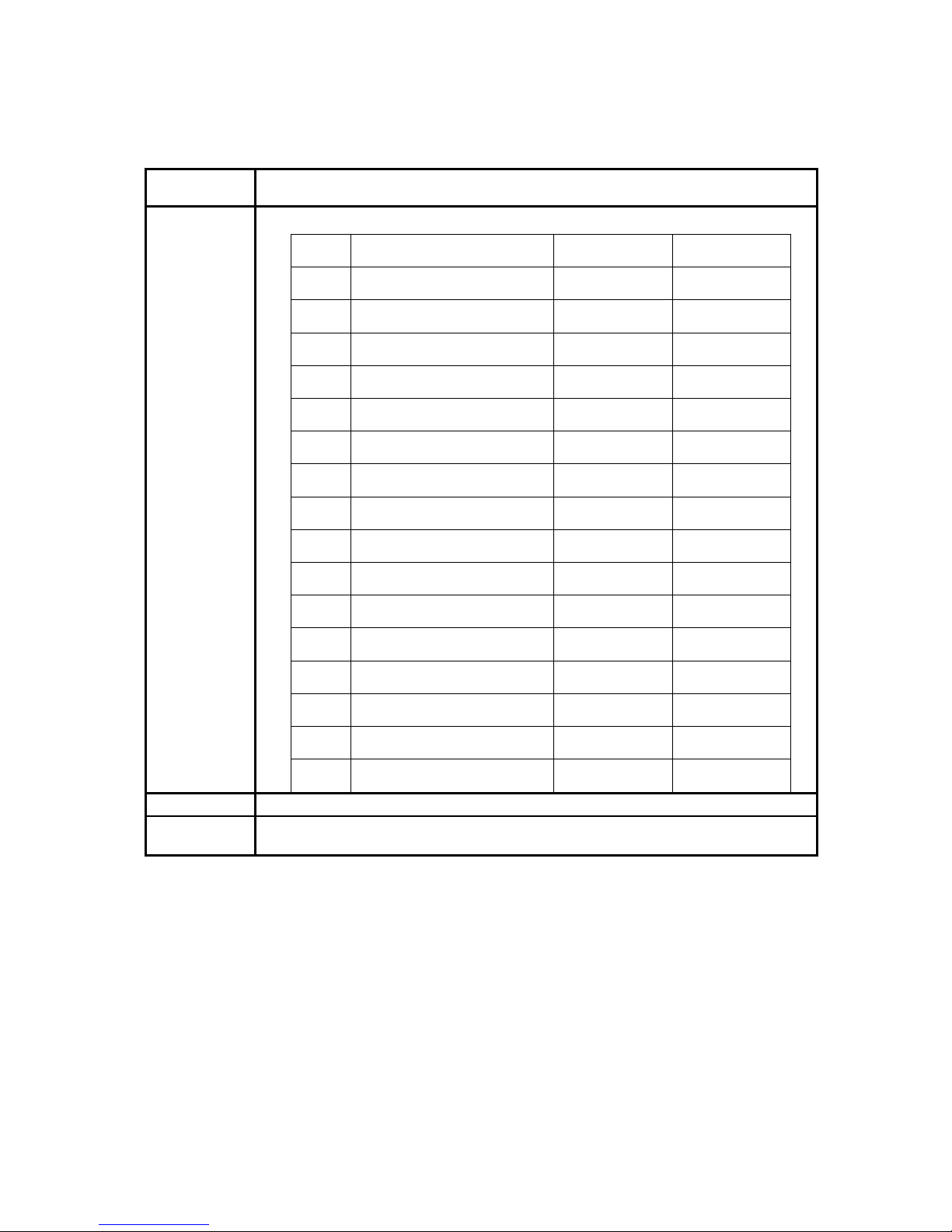
6.5.1 Command Data (Readable and Writable)
Register No. Content
101H
Operation Signal
Bit Description 1 0
0 Operation Command Run Stop
1 Reverse Command Reverse Forward
2 External Fault Fault (EFO)
3 Fault Reset Reset
4 Jog Command Jog
5 Multi-function Command S1 ON OFF
6 Multi-function Command S2 ON OFF
7 Multi-function Command S3 ON OFF
8 Multi-function Command S4 ON OFF
9 Multi-function Command S5 ON OFF
A Multi-function Command S6 ON OFF
B Multi-function Command AIN ON OFF
C Multi-function Command RY1 ON OFF
D Multi-function Command RY2 ON OFF
E (Not used)
F (Not used)
102H
Frequency Command
103H~11FH
(Reserved)
Note: Write in zero for Not used BIT, do not write in data for the reserved register.
Page 24
7300CV MODBUS COMMUNICATION PROTOCOL
File No. :PC-CV-08
Version : 1.A
Page :
24/34
6.5.2 Monitor Data (Only for reading)
Register No. Content
Bit Description 1 0
0 Operation state Run Stop
1 Direction state Reverse Forward
2 Inverter operation prepare state ready unready
3 Abnormal Abnormal
4 DATA setting error Error
5-F (unused)
120H
Fault Description
Code Description
Code Description
00 The inverter is normal 01 Program abnormal(CPF)
02 EEPROM abnormal (EPR) 03 Over voltage ( OV )
04 Under voltage( LV ) 05 Inverter over heat ( OH )
06~09 (unused) 10 Over current during decelerating ( OC-D )
11 Over current during accelerating ( OC-A ) 12 Over current at constant speed ( OC-C )
13
Over voltage at constant speed / decelerating
( OV-C )
14 Inverter over heat at constant speed ( OH-C )
15 Inverter over speed ( OVSP ) 16 CPU interrupted ( CTER )
17 (OC_S) 18~19 (Unused)
20 Over current at stop( OC ) 21 Motor over load (OL1)
22 Inverter over load ( OL2 ) 23 Over torque detected ( OL3 )
24 Under voltage during running ( LV-C ) 25~27 (unused)
28 (unused) 29 (Err8)
30 Stop at 0 Hz( STP0 ) 31 Direct start disable ( STP1 )
32 Control panel emergency stop ( STP2 ) 33 Emergency stop ( E.S )
34 External BB( bb ) 35 Auto testing error( ATER )
36 PID feedback signal loss( PDER ) 37 Communication error(EFO)
38 Encoder signal loss ( ECER ) *1 39 Analog converting error(Err4)
40 Parameter locked( LOC ) 41 Keypad operation error ( Err1 )
42 Parameter setting error ( Err2 ) 43
Modifying the parameter in
communication( Err5 )
44 Communication failure ( Err6 ) 45 Parameter setting error ( Err7 )
121H
Note: Write in zero for Not used BIT
Page 25

7300CV MODBUS COMMUNICATION PROTOCOL
File No. :PC-CV-08
Version : 1.A
Page :
25/34
Register No. Content
Bit Description 1 0
0 Terminal S1 Closed Opened
1 Terminal S2 Closed Opened
2 Terminal S3 Closed Opened
3 Terminal S4 Closed Opened
4 Terminal S5 Closed Opened
5 Terminal S6 Closed Opened
Sequence input
status
6 Terminal AIN Closed Opened
7~9 (unused)
A
Multi-function
output1(RELAY1)
ON OFF
B
Multi-function
output 1(RELAY2)
ON OFF
Contact output
C~F (unused)
122H
0123H
Frequency command
0124H
Output frequency
0125H
Output voltage command (1/1V)
0126H
Output DC voltage command (1/1V)
0127H
Output current (10/1A)
0128H
Reserved
0129H
Output torque
012AH
PID Feedback value (100% / Max output frequency, 10/1% )
012BH
PID input value (100% / Max output frequency, 10/1% , sign attached)
012CH
TM2 AIN input value (1024 / 10V) *1
012DH
TM2 AV2 input value (1024 / 10V) *1
Note: Write in zero for Not used BIT
Note: Do not write in data for the reserved register
Page 26

7300CV MODBUS COMMUNICATION PROTOCOL
File No. :PC-CV-08
Version : 1.A
Page :
26/34
6.5.3 Read the data in the holding register [03H]
Master unit reads the contents of the holding registers with the continuous numbers for the specified
quantity.
(Example) Read the SLAVE station No: 01, 7300CV drive's frequency command.
ASCII Mode
Instruction Message Response Message (Normal) Response Message (Fault)
3AH
STX
3AH
STX
3AH
STX
30H 30H 30H
31H
SLAVE
Address
31H
SLAVE
Address
32H
SLAVE
Address
30H 30H 38H
33H
Function
Code
33H
Function
Code
33H
Function
Code
30H 30H 35H
31H 32H
DATA
number
32H
Error Code
32H 31H 0DH
33H
Start Address
37H 0AH
END
30H 37H
30H 30H
First holding
register
30H ?
31H
Quantity
?
LRC CHECK
? 0DH
?
LRC CHECK
0AH
END
0DH
0AH
END
RTU Mode
Instruction Message Response Message (Normal) Response Message (Fault)
SLAVE Address
01 H SLAVE Address 01H SLAVE Address 02H
Function Code
03H Function Code 03H Function Code 83H
High
01H DATA number 02H Error Code 52H
Start Address
Low
23H
High
17H
High
C0H
High
00H
First holding
register
Low
70H
CRC-16
Low
CDH
Quantity
Low
01H
High
AFH
High
74H
CRC-16
Low
82H
CRC-16
Low
3CH
Page 27

7300CV MODBUS COMMUNICATION PROTOCOL
File No. :PC-CV-08
Version : 1.A
Page :
27/34
6.5.3 Loop back testing [08H]
The function code is check communication between MASTER and SLAVE, the Instruction message is
returned as a response message without being change, Any values can be used for test codes or data
ASCII Mode
Instruction Message Response Message (Normal) Response Message (Fault)
3AH STX 3AH STX 3AH STX
30H 30H 30H
31H
SLAVE
Address
31H
SLAVE
Address
31H
SLAVE
Address
30H 30H 38H
38H
Function
Code
38H
Function
Code
38H
Function
Code
30H 30H 32H
30H 30H 30H
Error Code
30H 30H ?
30H
Test Codes
30H
Test Codes
?
LRC CHEC
0DH
41H 41H
0AH
END
35H 35H
33H 33H
37H
DATA
37H
DATA
? ?
?
LRC CHECK
?
LRC CHECK
0DH 0DH
0AH
END
0AH
END
RTU Mode
Instruction Message Response Message (Normal) Response Message (Fault)
SLAVE Address 01 H SLAVE Address 01H SLAVE Address 01H
Function Code 08H Function Code 08H Function Code 88H
High
00H
High
00H Error Code 20H Test
Codes
Low 00H
Test
Codes
Low 00H
High
47H
High
A5H
High
A5H
CRC-16
Low
D8H
DATA
Low
37H
DATA
Low
37H
High
DAH
High
DAH
CRC-16
Low
8DH
CRC-16
Low
8DH
Page 28
7300CV MODBUS COMMUNICATION PROTOCOL
File No. :PC-CV-08
Version : 1.A
Page :
28/34
6.5.3 Write holding register [06H]
The specified data are written into the specified holding register.
(Example) Set SLAVE station No: 01, 7300CV drive's frequency command is 60.0Hz.
ASCII Mode
Instruction Message Response Message (Normal) Response Message (Fault)
3AH STX 3AH STX 3AH STX
30H 30H 30H
31H
SLAVE
Address
31H
SLAVE
Address
31H
SLAVE
Address
30H 30H 38H
36H
Function Code
36H
Function
Code
36H
Function
Code
30H 30H 35H
31H 31H 32H
Error Code
30H 30H ?
32H
Start Address
32H
Start Address
?
LRC CHECK
0DH
31H 31H
0AH
END
37H 37H
37H 37H
30H
DATA
30H
DATA
? ?
?
LRC CHECK
?
LRC CHECK
0DH 0DH
0AH
END
0AH
END
RTU Mode
Instruction Message Response Message (Normal) Response Message (Fault)
SLAVE Address 01 H SLAVE Address 01H SLAVE Address 01H
Function Code 06H Function Code 06H Function Code 86H
High
01H
High
01H Error Code 52H Start
Address
Low 02H
Start
Address
Low 02H
High
C3H
High
17H
High
17H
CRC-16
Low
9DH
DATA
Low 70H
DATA
Low 70H
High
27H
High
27H
CRC-16
Low E2H
CRC-16
Low E2H
Page 29

7300CV MODBUS COMMUNICATION PROTOCOL
File No. :PC-CV-08
Version : 1.A
Page :
29/34
6.5.3Write in several holding registers [10H]
Specified data are written into the several specified holding registers from the specified number,
respectively.
(Example) Set SLAVE station No: 01, 7300CV drive as forward run at frequency reference 60.0Hz
ASCII Mode
Instruction Message Response Message (Normal) Response Message (Fault)
3AH
STX
3AH
STX
3AH
STX
30H 30H 30H
31H
SLAVE
Address
31H
SLAVE
Address
31H
SLAVE
Address
31H 31H 39H
30H
Function
Code
30H
Function
Code
30H
Function
Code
30H 30H 35H
31H 31H 32H
Error Code
30H 30H ?
31H
Start Address
31H
Start Address
?
LRC CHECK
0DH
30H 30H
0AH
END
30H 30H
30H 30H
32H
Quantity
32H
Quantity
30H ?
34H
DATA
Number*
?
LRC CHECK
30H 0DH
30H 0AH
END
30H
31H
First DATA
31H
37H
37H
30H
Next DATA
?
?
LRC CHECK
0DH
0AH
END
* Data numbers are the actual number times 2
Page 30

7300CV MODBUS COMMUNICATION PROTOCOL
File No. :PC-CV-08
Version : 1.A
Page :
30/34
RTU Mode
Instruction Message Response Message (Normal) Response Message (Fault)
SLAVE Address
01 H
SLAVE Address
01H
SLAVE Address
01H
Function Code
10H
Function Code
10H
Function Code
90H
High
01H
High
01H
Error Code
52H
Start
Address
Low
01H
Start
Address
Low
01H
High
CDH
High
00H
High
00H
CRC-16
Low
FDH
Quantity
Low
02H
Quantity
Low
02H
DATA Number *
04H
High
11H
High
00H
CRC-16
Low
Low
F4H
First DATA
Low
01H
High
17H
Next DATA
Low
70H
High
60H
CRC-16
Low
27H
* Data numbers are the actual number times 2
Page 31

7300CV MODBUS COMMUNICATION PROTOCOL
File No. :PC-CV-08
Version : 1.A
Page :
31/34
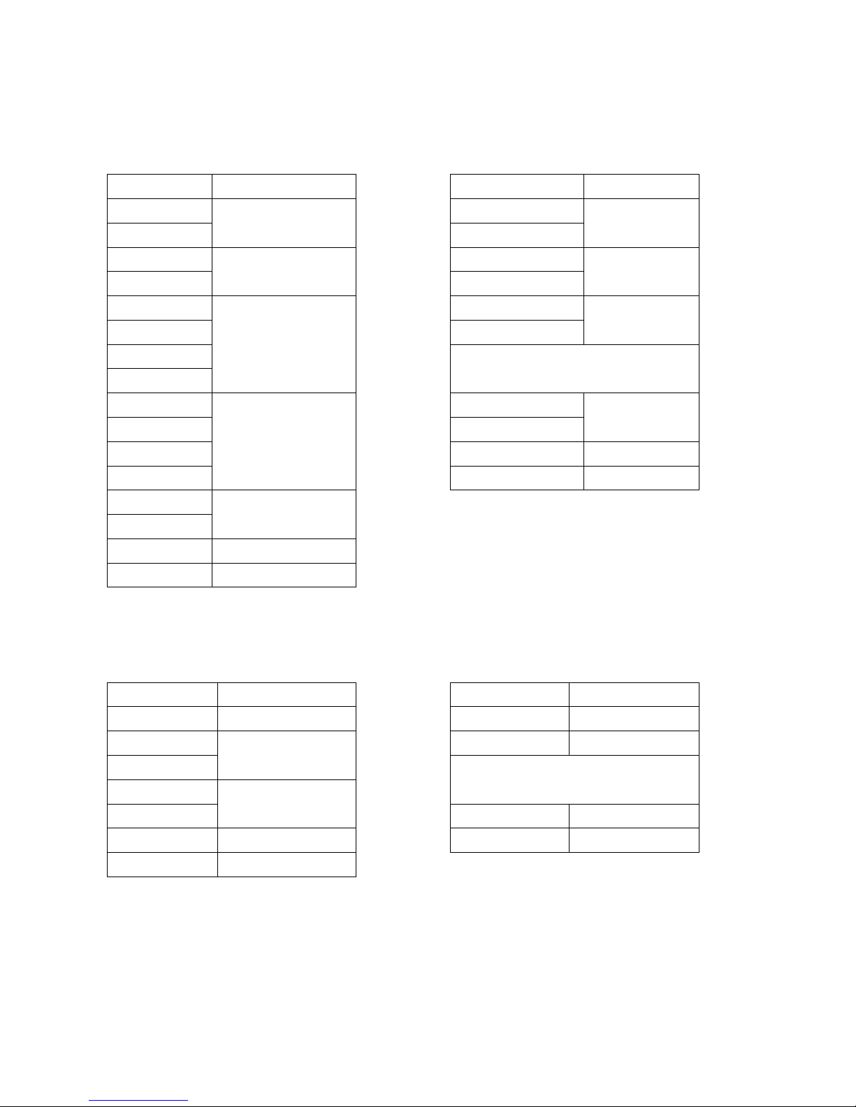
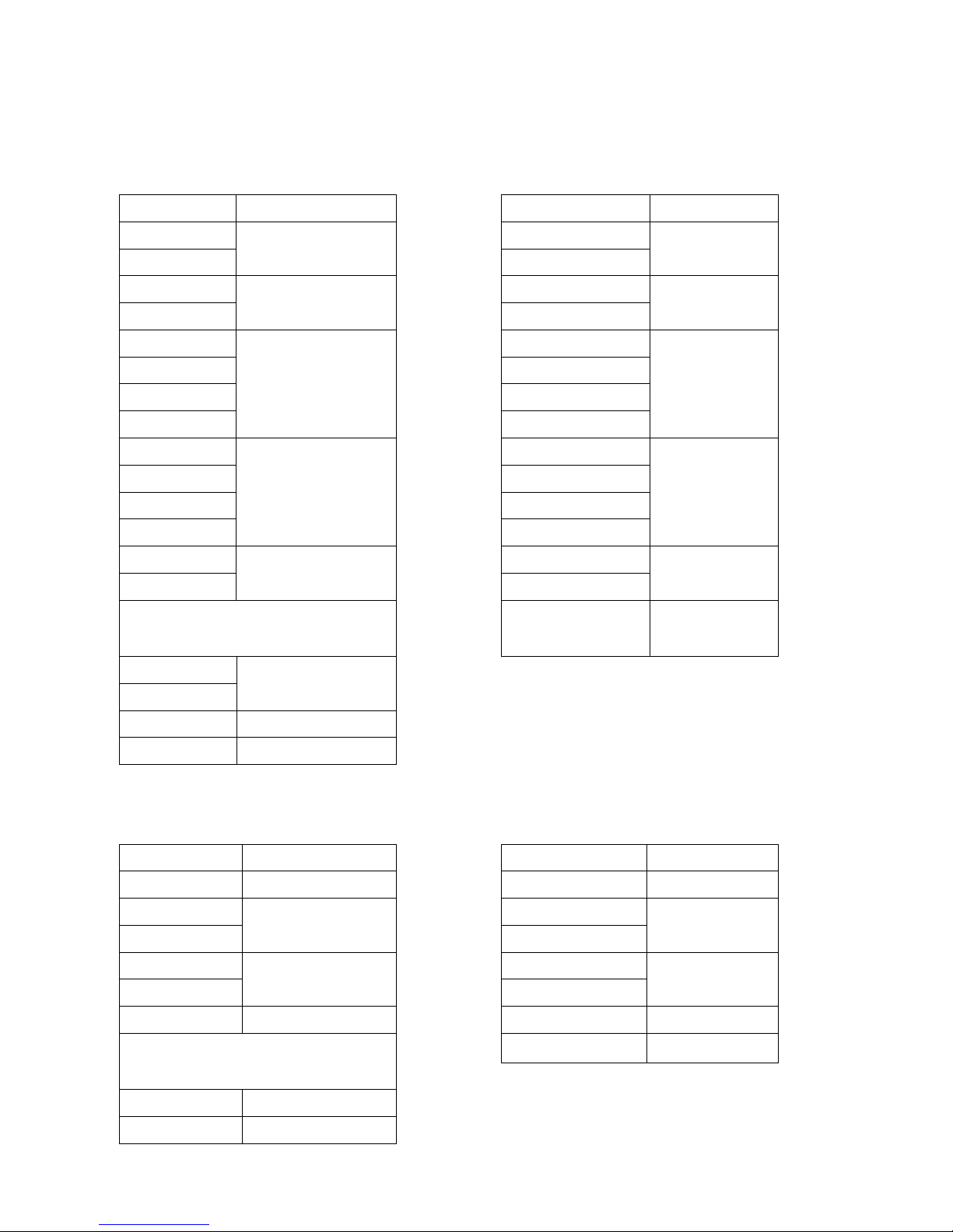
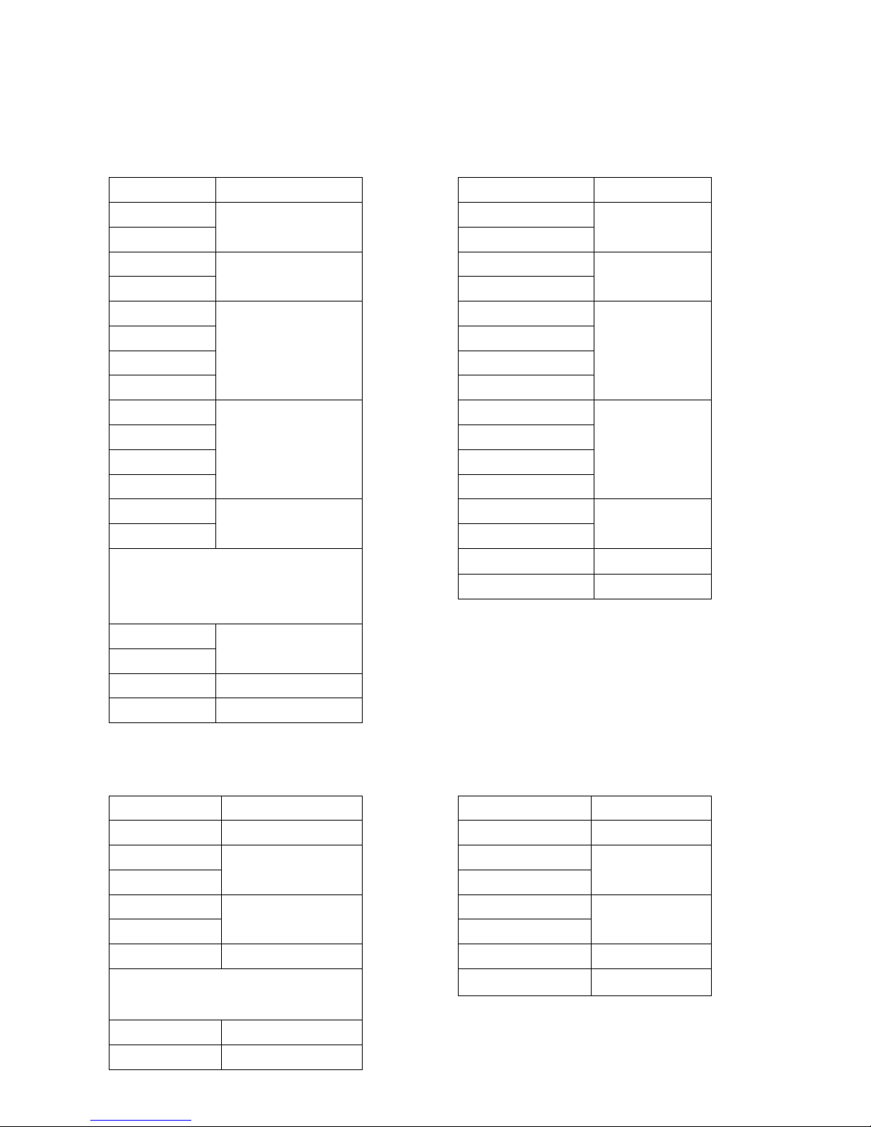
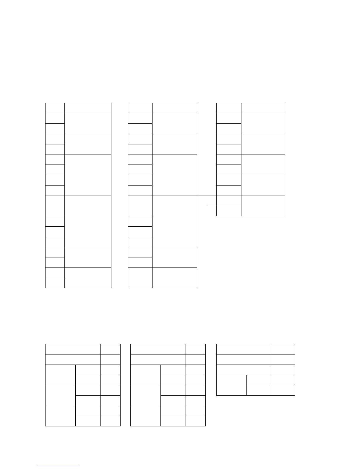
Comparison list between parameter and register
Register
No.
Function
Register No. Function
0000H
0-0
0023H
3-11
0001H 0-1 0024H 3-12
0002H 0-2 0025H 3-13
0003H 0-3 0026H 3-14
0004H 0-4 0027H 3-15
0005H 0-5 0028H 3-16
0006H 0-6 0029H 3-17
0007H 0-7 002AH 3-18
0008H 0-8 002BH 3-19
0009H
1-0
002CH
3-20
000AH
1-1
002DH
3-21
000BH
1-2
002EH
3-22
000CH
1-3
002FH
4-0
000DH
1-4
0030H
4-1
000EH
1-5
0031H
4-2
000FH
1-6
0032H
4-3
0010H
1-7
0033H
4-4
0011H
2-0
0034H
4-5
0012H
2-1
0035H
5-0
0013H
2-2
0036H
5-1
0014H
2-3
0037H
5-2
0015H
2-5
0038H
5-3
0016H
2-6
0039H
5-4
0017H
2-7
003AH
5-5
0018H
3-0
003BH
5-6
0019H 3-1 003CH 5-8
001AH 3-2 003DH 5-7
001BH 3-3 003EH 6-0
001CH 3-4 003FH 6-1
001DH 3-5 0040H 6-2
001EH 3-6 0041H 6-3
001FH 3-7 0042H 6-4
0020H
3-8
0043H
6-5
0021H
3-9
0044H 6-6
0022H 3-10 0045H 6-7
Page 32

7300CV MODBUS COMMUNICATION PROTOCOL
File No. :PC-CV-08
Version : 1.A
Page :
32/34
Register
No.
Function
Register No. Function
0046H
6-8
0069H
10-6
0047H
7-0
006AH
10-7
0048H
7-1
006BH
10-8
0049H
7-2
006CH
10-9
004AH
7-3
006DH
11-0
004BH
7-4
006EH
11-1
004CH
7-5
006FH
11-2
004DH
8-0
0070H
11-3
004EH
8-1
0071H
11-4
004FH
8-2
0072H
11-5
0050H
8-3
0073H
11-6
0051H
8-4
0074H
11-7
0052H
8-5
0075H
12-0
0053H
9-0
0076H
12-1
0054H
9-1
0077H
12-2
0055H
9-2
0078H
12-3
0056H
9-3
0079H
12-4
0057H
9-4
007AH
12-5
0058H
9-5
007BH
12-6
0059H
9-6
007CH
13-0
005AH
9-7
007DH
13-1
005BH
9-8
007EH
13-2
005CH
9-9
007FH
13-3
005DH
9-10
0080H
13-4
005EH
9-11
0081H
14-0
005FH 9-12 0082H 14-1
0060H 9-13 0083H 14-2
0061H 9-14 0084H 14-3
0062H 9-15 0085H 14-4
0063H 10-0 0086H 15-0
0064H 10-1 0087H 15-1
0065H 10-2 0088H 15-2(1)
0066H
10-3
0089H
15-2(2)
0067H
10-4
008AH 15-2(3)
0068H 10-5 008BH 15-3
Page 33

7300CV MODBUS COMMUNICATION PROTOCOL
File No. :PC-CV-08
Version : 1.A
Page :
33/34
Register
No.
Function
Register No. Function
008CH
15-4
00AFH ~
008DH
15-5
00B0H ~
008EH
15-6
00B1H ~
008FH
00B2H ~
0090H
3-23
00B3H ~
0091H
3-24
00B4H ~
0092H
3-25
00B5H ~
0093H
3-26
00B6H ~
0094H
3-27
00B7H ~
0095H
3-28
00B8H ~
0096H
3-29
00B9H ~
0097H
5-9
00BAH ~
0098H
~
00BBH ~
0099H
2-4
00BCH ~
009AH
2-8
00BDH ~
009BH
12-7
00BEH ~
009CH
12-8
00BFH ~
009DH
4-6
00C0H ~
009EH
5-10
00C1H ~
009FH
5-11
00C2H ~
00A0H ~ 00C3H ~
00A1H ~ 00C4H ~
00A2H ~ 00C5H ~
00A3H ~ 00C6H ~
00A4H ~ 00C7H ~
00A5H ~ 00C8H ~
00A6H ~ 00C9H ~
00A7H ~ 00CAH ~
00A8H ~ 00CBH ~
00A9H ~ 00CCH ~
00AAH ~ 00CDH ~
00ABH ~ 00CEH ~
00ACH ~ 00CFH ~
00ADH ~ 00D0H ~
00AEH ~ 00D1H ~
Page 34

7300CV MODBUS COMMUNICATION PROTOCOL
File No. :PC-CV-08
Version : 1.A
Page :
34/34
Register
No.
Function
Register No. Function
00D2H
~
00F7H ~
00D3H ~ 00F8H ~
00D4H ~ 00F9H ~
00D5H ~ 00FAH ~
00D6H ~ 00FBH ~
00D7H ~ 00FCH ~
00D8H ~ 00FDH ~
00D9H ~ 00FEH ~
00DAH ~ 00FFH ~
00DBH ~
00DCH ~
00DDH ~
00DEH ~
00DFH ~
00E0H ~
00E1H ~
00E2H ~
00E3H ~
00E4H ~
00E5H ~
00E6H ~
00E7H ~
00E8H ~
00E9H ~
00EAH ~
00EBH ~
00ECH ~
00EDH ~
00EEH ~
00EFH ~
00F0H ~
00F1H ~
00F2H ~
00F3H ~
00F4H ~
00F5H ~
00F6H ~
 Loading...