

Page 1

Automotive Equipment
Instruction Manual
EN
TYRE CHANGERS
TECO 22 - TECO 23
TECO 25 - TECO 27 Special
Version 2.2 - April 2016
Page 2

2 User’s manual - TECO 22 - 23 - 25 - 27 Special
Elaborazione graca e impaginazione
Ufcio Pubblicazioni Tecniche
I
diritti di traduzione, di memorizzazione elettronica, di
riproduzione e di adattamento totale o parziale con qualsiasi
mezzo (compresi microlm e copie fotostatiche) sono riservati.
Le informazioni contenute in questo manuale sono soggette a
variazioni senza preavviso.
A
ll rights of total or partial translation, electronic storage,
reproduction and adaptation by any means (including
microlm and photocopies) are reserved.
The information in this manual is subject to variation without
notice.
L
es droits de traduction, de mémorisation électronique, de
reproduction et d’adaptation totale ou partielle par n’importe
quel moyen (y compris microlms et copies photostatiques)
sont réservés.
Les informations contenues dans ce manuel sont sujettes à
des variations sans préavis.
A
lle Rechte der Übersetzung, elektronischen Speicherung,
Vervielfältigung und Teil- oder Gesamtanpassung unter
Verwendung von Mitteln jedweder Art (einschließlich Mikrolm
und fotostatische Kopien) sind vorbehalten.
Die im vorliegenden Handbuch enthaltenen Informationen
können jederzeit ohne Vorankündigung geändert werden.
Q
uedan reservados los derechos de traducción, de memori-
zación electrónica, de reproducción y de adaptación total o
parcial con cualquier medio (incluidos microlmes y fotocopias).
Las informaciones que se incluyen en este manual están sujetas
a variaciones sin aviso previo.
English
Italiano
Español
Deutsch
Français
Page 3

User’s manual - TECO 22 - 23 - 25 - 27 Special 3
ORIGINAL INSTRUCTIONS
CONTENTS
INTRODUCTION .............................................................................................4
TRANSPORT, STORAGE AND HANDLING ................................................... 5
UNPACKING/ASSEMBLY ...............................................................................6
HOISTING/HANDLING ....................................................................................6
INSTALLATION ...............................................................................................7
ELECTRICAL AND PNEUMATIC CONNECTIONS .........................................8
SAFETY REGULATIONS ................................................................................9
DESCRIPTION ..............................................................................................10
MANUFACTURER’S LABEL .........................................................................10
TECHNICAL DATA ....................................................................................... 11
STANDARD ACCESSORIES ........................................................................12
ACCESSORIES SUPPLIED ON DEMAND ...................................................12
SPECIFIED CONDITIONS OF USE ..............................................................12
MAIN OPERATING PARTS ........................................................................... 13
WARNING SIGNALS .....................................................................................15
PRACTICAL HINTS .......................................................................................16
USE ............................................................................................................... 17
DEMONTAGE ................................................................................................ 18
MONTAGE ..................................................................................................... 19
INFLATION ....................................................................................................20
MAINTENANCE ............................................................................................ 21
ENVIRONMENTAL INFORMATION ..............................................................24
INFORMATION AND WARNINGS ABOUT OIL .............................................25
RECOMMENDED FIRE-EXTINGUISHING DEVICES ..................................26
GLOSSARY ...................................................................................................27
TROUBLE SHOOTING ................................................................................. 27
ELECTRICAL SYSTEM DIAGRAM ...............................................................28
PNEUMATIC SYSTEM DIAGRAM ................................................................31
Page 4

4 User’s manual - TECO 22 - 23 - 25 - 27 Special
INTRODUCTION
The purpose of this manual is to furnish the owner and operator with a set of practical, safe instructions on the use and maintenance of the TECO tyre changer.
Follow all the instructions carefully and the machine will give you the efcient and long-lasting service
that has always characterized TECO products, making your work considerably easier.
The following points dene the levels of danger regarding the machine, associated with the warning
captions found in this manual:
DANGER
Refers to immediate danger with the risk of serious injury or even death.
WARNING
Dangers or unsafe procedures that can cause serious injury or even death.
CAUTION
Dangers or unsafe procedures that can cause minor injuries or damage to property.
Read these instructions carefully before powering up the machine. Keep this manual and all illustrative
material supplied with the machine in a folder near the tyre changer where it is readily accessible for
consultation by the machine operators.
The technical documentation supplied is considered an integral part of the machine; and must always
accompany the equipment if it is sold or transferred to a new owner.
The manual is only to be considered valid for the model with the serial number indicated on the
nameplate applied to it.
WARNING
Observe the contents of this manual: the producer declines all liability in the case of uses of
the machine not specically described and authorized in this manual.
WARNING
This machine must be used only by qualied and authorized personnel. A qualied operator
is construed as a person who has read and understood the tyre changer manufacturer’s
instructions as well as the tyres and wheel rims manufacturers’, is suitably trained, and is
conversant with safety and adjustment procedures to be adhered to during operations. Use
of the machine by unskilled staff may constitute a serious risk for the operator and for the
nal user of the product processed (the wheel rim and tyre assembly).
NB:
Some of the illustrations in this manual have been taken from photographs of prototypes: standard
production machines may vary in some respects.
These instructions are intended for people with basic mechanical skills. We have therefore omitted
detailed descriptions of procedures such as how to loosen or tighten the xing devices on the machine. Do not attempt to perform operations unless properly qualied and with suitable experience.
In case of need, contact an authorized Service Centre for assistance.
Page 5
User’s manual - TECO 22 - 23 - 25 - 27 Special 5
TRANSPORT, STORAGE AND HANDLING
Conditions for transporting the machine
The tyre changer must be transported in its original packing and stowed in the position shown on
the external packing.
- Packing dimensions (Teco 22 - 23 - 25 - 27 Sp.):
• width ................................................................................................................................765 mm
• depth ...............................................................................................................................980 mm
• height ...............................................................................................................................970 mm
- Weight of the machine with packing (Teco 22 - 23 - 25 - 27):
• standard ............ (TECO 22: 170kg; TECO 23: 183kg; TECO 25: 193kg; TECO 27 Sp.: 200kg)
• t.i. version ......................................(TECO 23: 198kg; TECO 25: 208kg; TECO 27 Sp.: 215kg)
Ambient conditions for machine transport and storage
Temperature: -25° ÷ +55°C.
WARNING
Do not stack other goods on top of the packing to avoid damaging it.
Handling
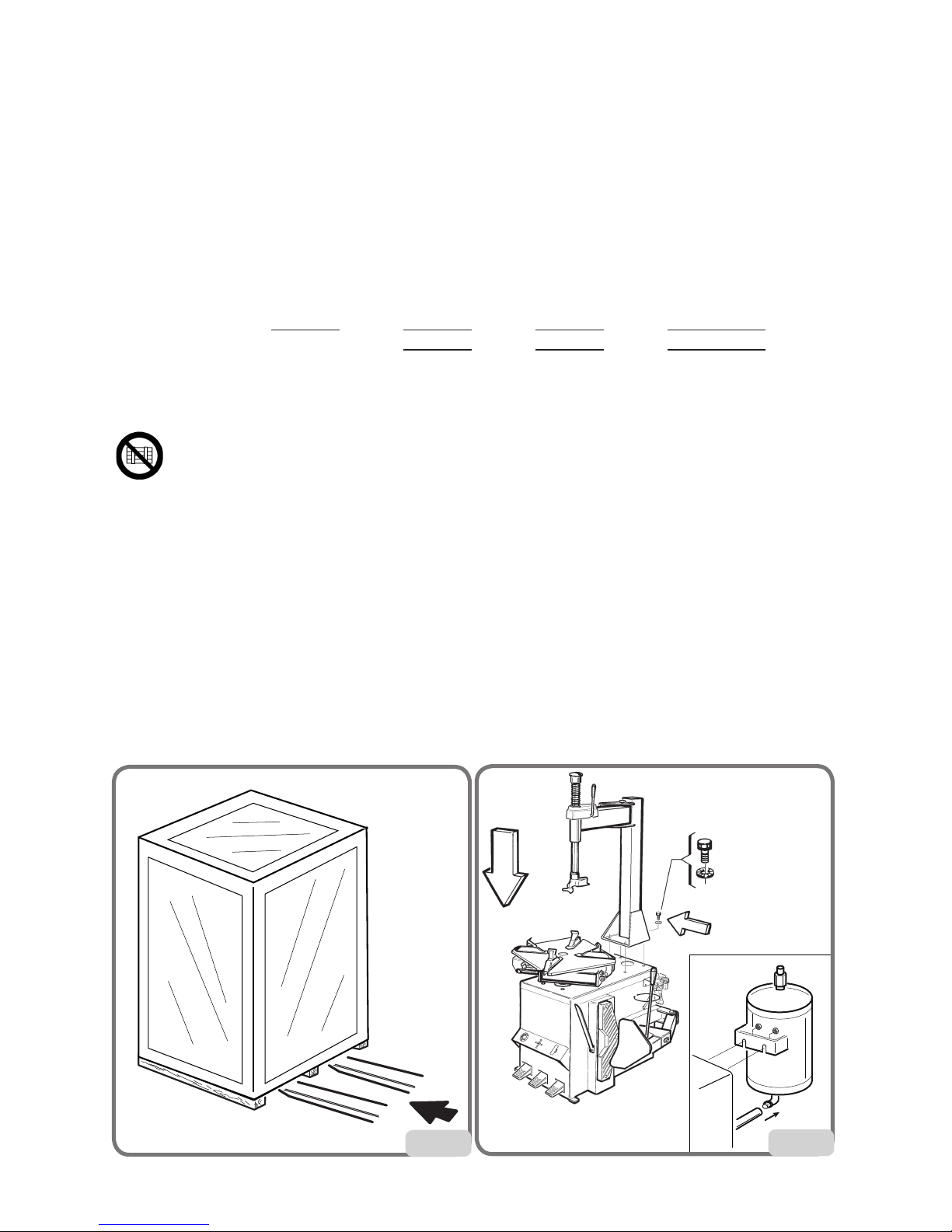
To move the packing, insert the tines of a fork-lift truck into the slots on the base of the packing itself
(pallet) (g. 1).
ATTENTION
Carry out the moving operations with great care, paying attention to move the packaged machine
only from the side clearly indicated on the packaging.
Failure to follow these recommendations may result in damage to the machine and put the operator’s
safety at risk.
Before moving the machine, refer to the HOISTING/HANDLING section.
1
1a
Page 6

6 User’s manual - TECO 22 - 23 - 25 - 27 Special
UNPACKING/ASSEMBLY
WARNING
Take utmost care when unpacking, assembling, hoisting and installing the machine as described
in this heading.
Keep the original packing in good conditions to be used if the equipment has to be shipped in the
future and make sure that the machine has not suffered damage in transit.
Failure to comply with these instruction may damage the machine and risk the operator’s safety.
Remove the upper part of the packing.
Proceed with the following operations:
- Remove the tower (horizontal + vertical arms) from their position on the pallet.
- Fit the tower into the threaded holes.
- Fasten the tower on the machine’s body with the screw; do not forget to interpose the not ched
washers wihch allow the electric continuity of the machine.
- Assemble the bead breaker with the proper pin and fasten it with the locknut until there is a slight
resistance in the rotation of the bead breaker.
- Connect the tank union to the air connection pipeline provided, securing it with a band clamp.
Fix the air tank to the machine (g.1a).(T.I. version only).
HOISTING/HANDLING
To remove the machine from the pallet :
Lift the machine sideways enough to insert the forks of the fork-lift truck between the machine and
the pallet as showed in g.2.
At this point is possible to release the working arm removing the cord which binds the arm to the
turntable.This hoisting point must be used whenever you need to change the installation position of
the machine. Do not attempt to move the machine until it has been disconnected from the electricity
and compressed air supply systems.
2
®
3
800
800
700
®
Page 7

User’s manual - TECO 22 - 23 - 25 - 27 Special 7
INSTALLATION CLEARANCES
WARNING
The installation site must be chosen in strict compliance with the relevant regulations regarding
Safety in the workplace.
IMPORTANT: for correct, safe use of the equipment, users must ensure a lighting level of at least
300 lux in the place of use.
CAUTION
The installation of the machine must be performed in a dry area which must be protected
from adverse weather conditions.
Install the tyre changer in the chosen work position, complying with the minimum clearances shown
in g. 3, adjust the height of the bead breaking support foot so that the machine is correctly positioned on the ooring.
Place the machine so that the plug-socket combination is easily accessible.
The machine must be placed on a horizontal surface, preferably concrete or tiled oor. Do not install
on unstable or damaged surfaces.
The surface on which the machine rests must withstand the loads transmitted during operation. The
surface must have a load-carrying capacity of at least 500 kg/m2.
Ambient working conditions
- Relative humidity 50% (temp. 40°C) ÷ 90% (temp. 20°C) without condensation.
- Temperature 5°C ÷ 40°C.
WARNING
Use of the machine in a potentially explosive atmosphere is not permitted.
A
B
5
4
®
Page 8

8 User’s manual - TECO 22 - 23 - 25 - 27 Special
ELECTRICAL AND PNEUMATIC CONNECTIONS
WARNING
All operations required for the electrical connections of the equipment must be carried out
exclusively by a quali ed electrician.
Before connecting the air supply system, make sure the machine is set up as in g. 4:
pedal totally downwards.
- The electrical supply must be suitably sized in relation to:
• the machine input power as speci ed in the corresponding machine data plate;
• the distance between the machine and the power supply hook-up point, so that voltage drops
under full load do not exceed 4% (10% during start-up) compared with the rated voltage speci ed
on the data plate.
- The operator must:
• t a power plug on the power supply lead in compliance with the relevant safety standards (A g 5);
• Connect the machine to an ef cient grounding circuit in compliance with the relevant electric stan-
dards, provided with a circuit breaker (residual current set to 30mA);
• t fuses to protect the power supply line, rated as indicated on the general wiring diagram in this
manual.
- In order to prevent the machine from being used by unauthorized personnel, it is advisable to
disconnect the power supply plug when the machine remains idle (switched off) for long periods.
WARNING
A good grounding connection is essential for correct operation of the machine.
NEVER connect the earth wire to a gas or water pipe, telephone line or any other unsuitable
objects.
Check that the pressure and ow-rate provided by the compressed air system are compatible with
those required for proper operation of the machine - see “Technical Data” section. For correct machine
operation the compressed air supply line must provide a pressure range from no less than 8 bar to
no more than 16 bar.
Connect the compressed air system by means of a supply pipe connected to the intake of the air
treatment unit on the REAR SIDE of the machine base.
Check that there is air lubrication oil in the Lubricating unit; re ll if there is little or no oil. Use SAE20 oil.
The customer must provide an air cut-off valve upstream of the air treatment and regulating device
supplied with the machine.
WARNING
Connection 1 should be considered as an emergency valve to
disconnect the machine from the air line ( g.6)
1
6
Page 9

User’s manual - TECO 22 - 23 - 25 - 27 Special 9
SAFETY REGULATIONS
The equipment is intended for professional use only.
WARNING
Only one operator may work on the equipment at a time.
WARNING
Failure to comply with the instructions and danger warnings may seriously injure operators
and any other person present near the machine. Do not operate the machine until you have
read and understood all the danger, warning and caution notices in this manual.
This machine must be used only by qualied and authorized personnel. A qualied operator is construed
as a person who has read and understood the manufacturer’s instructions, is suitably trained, and
is conversant with safety and adjustment procedures to be adhered to during operations. Operators
must not use the machine under the inuence of alcohol or drugs which may affect their capacity.
The operator must, in all cases:
- Be able to read and understand all the information in this manual.
- Have a thorough knowledge of the capabilities of this machine.
- Keep unauthorized persons well clear of the area of operation.
- Make sure the machine has been installed in compliance with all relevant regulations and legislation.
- Make sure that all machine operators are suitably trained, that they are capable of using the
equipment correctly and that they are adequately supervised.
- Never leave nuts, bolts, tools or any other equipment on the tyre changer as they may become
entrapped between moving parts.
- Not touch power lines or the inside of electric motors or any other electrical equipment before
making sure the power supply has been disconnected.
- Read this manual carefully and learn how to use the machine correctly and safely.
- Always keep this user and maintenance manual in an easily accessible place and consult it
whenever necessary.
WARNING
Do not remove or deface the Danger, Warning or Instruction decals. Replace any missing or
illegible decals. If one or more decals have been detached or damaged, replacements can be
obtained from your nearest dealer.
- When using and servicing the machine, observe the standardized industrial accident
prevention regulations for high voltages.
- Any unauthorized alterations or changes made to the machine shall automatically release the
manufacturer from any liability for damage or accidents attributable to such modications.
Specically,tampering with or removing the safety devices is a breach of the regulations for Safety
in the workplace.
- User must wear personal protective equipment such as gloves, safety footwear and goggles.
WARNING
When operating or servicing the equipment, tie back long hair and do not wear loose-tting clothes,
ties, necklaces, rings or wristwatches which could become entrapped by moving parts.
Page 10
10 User’s manual - TECO 22 - 23 - 25 - 27 Special
DESCRIPTION
The machine is a electro-pneumatic tyre changer semi-automatic, to be used with wheels with drop
centre featuring weights and dimensions as described in the technical data section.
It is designed to work effectively on:
- Conventional wheels;
- Reverse rim wheels or wheels without central hole (use optional kit);
- Run-at tyres with reinforced sidewalls*.
* WARNING: There are specically studied procedures for this type of wheels.
NB: It may be difcult and sometimes impossible to clamp and/or demount wheels of Vintage
cars (cars out of production for over 30 years), some types of rally wheels and non-standardized
street wheels.
The machine is solidly constructed. It operates with the wheel in a vertical position for bead breaking
and horizontal for mounting and demounting tyres. All machine movements are controlled by the
operator by means of the pedals.
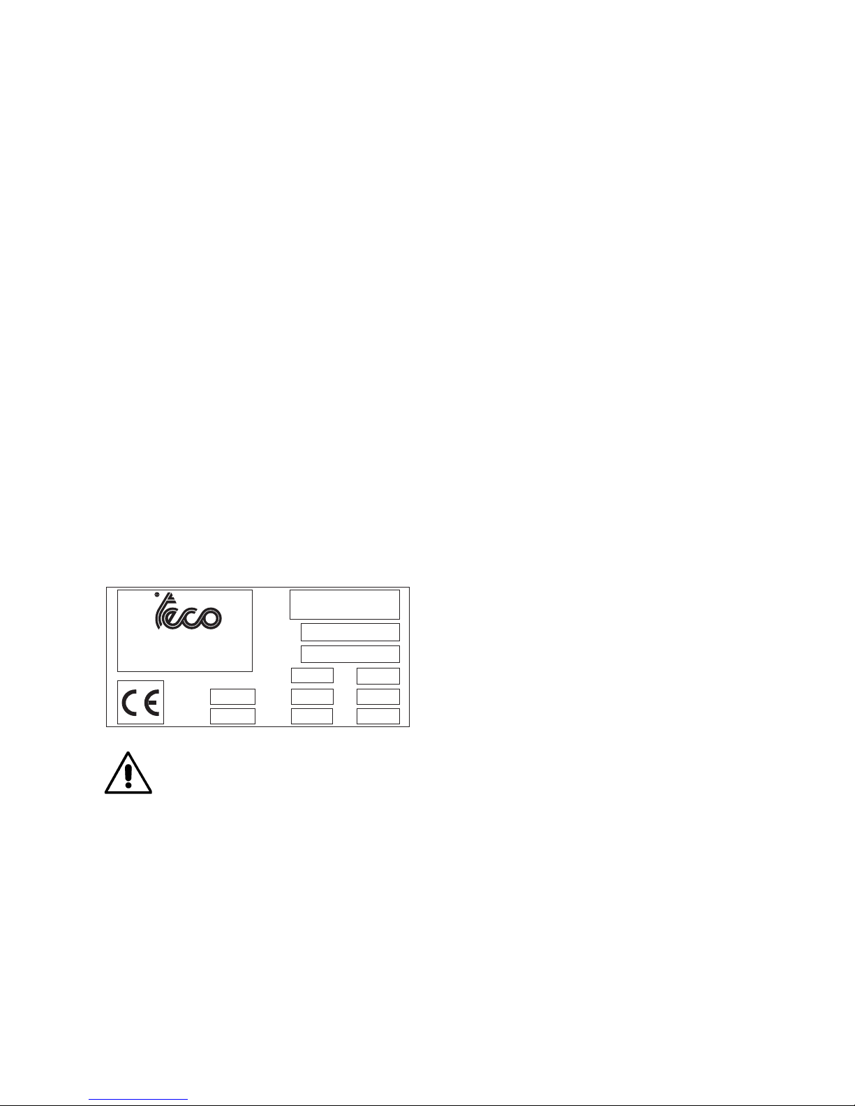
MANUFACTURER’S LABEL
Each machine carries a plate with its identication and some technical data.
As well as the manufacturer’s details, it indicates:
Mod. - Machine model;
V - power supply voltage in Volts;
A - Input voltage in Amperes;
kW - Absorbed power in kW;
Hz - Frequency in Hz;
Ph - Number of phases;
bar - Operating pressure in bar;
Serial No. - Machine serial number;
EC - EC marking.
Mod.
Ser. N.
Volt
Kw
Amp.
Year
Weight
Ph
Hz
Bar
Automotive Equipment
TECO s.r.l. Via Pio La Torre 10
42015 Correggio (R.E.) - ITALY
tel. 0522/631562 - fax 0522/642373
WARNING
It is forbidden to modify or remove the data in the plate.
Page 11

User’s manual - TECO 22 - 23 - 25 - 27 Special 11
TECHNICAL DATA
- Overall dimensions (Teco 22 - Teco 23 - Teco 25 - Teco 27 Sp. - see g. 7):
• Length ............................................................................................. 900/1200 (t.i.) min 1260 max
• Width .............................................................................................................. 820 min 1200 max
• Height ........................................................................................................... 1520 min 1820 max
- Table top clamping capacity (Teco 22 - Teco 25):
• inside clamping .................................................................................................................. 13”-21”
• outside clamping ................................................................................................................. 10”-18”
- Table top clamping capacity (Teco 23):
• inside clamping .................................................................................................................. 13”-23”
• outside clamping ................................................................................................................. 10”-20”
- Table top clamping capacity (Teco 27 Sp.):
• inside clamping .................................................................................................................. 14”-24”
• outside clamping ................................................................................................................. 12”-22”
- Rim width: ............................................................................................................................335 mm
- Maximum tyre diameter: ....................................................................................................1000 mm
- Bead breaking pressure: ................................................................................................... .2900 Kg
- Air pressure ........................................................................................................................8-10 Bar
- Motor electrical features:
• 1ph version - 1 speed 220V - 50Hz ................................................................. 6A - 0,75 kW
• 3ph version - 1 speed 230V - 50Hz ............................................................. 2,8A - 0,55 kW
• 3ph version - 1 speed 400V - 50Hz ............................................................. 1,6A - 0,55 kW
• 3ph version - 2 speed 230V - 50Hz ................................................... 5,3/6,8A - 0,8/1,1 kW
• 3ph version - 2 speed 400V - 50Hz ................................................... 2,8/4,4A - 1,1/1,5 kW
- Weight (Teco 22) ...................................................................................................................150 kg
- Weight (Teco 23) ................................................................................................163 kg (178 kg t.i.)
- Weight (Teco 25) ................................................................................................173 kg (188 kg t.i.)
- Weight (Teco 27 Sp.) .........................................................................................185 kg (200 kg t.i.)
- Weight of electrical/ electronic components: ........................................................................ 11,5 kg
- Noise level: A-weighted sound pressure level (LpA) at the working position ...... < 70 dB (A)±3dB(A)
The noise levels indicated correspond to emission levels and do not necessarily represent safe
operating levels. Although there is a relationship
between emission levels and exposure levels,
thiscan not be used reliably to establish whether
or not further precautions are necessary. The
factors which determine the level of exposure
to which the operator is subject to include the
duration of the exposure, the characteristics of
the workplace, other sources of noise, etc. The
permitted exposure levels may also vary according to the country. However, this information will
enable machine users to make a more accurate
assessment of hazard and risks.
7
Min 820 - Max 1200
Min 1520 - Max 1820
Min 900/1200 - Max 1260
(t.i.)
Page 12

12 User’s manual - TECO 22 - 23 - 25 - 27 Special
STANDARD ACCESSORIES
044900800.........................................................................................................................Tyre lever
040000100.......................................................................................................................Brush (BR)
3-01523 ................................................................................................................Grease 4Kg (TG4)
ACCESSORIES ON DEMAND
100012100........................................................................................................................... UWA 24
(Adapters to increase the turntable clamping capacity (to be used in combination with US TPH)
100012000................................................................................................................................ UMA
Universal motorcycle adapters
100001500.................................................................................................................................CRA
Adapters for convex rims
8-11600005............................................................................................................................. PLS 2
(Pneumatic wheel lift complete with roller rest)
SPECIFIED CONDITIONS OF USE
The TECO tyre changers has been designed exclusively for mounting and demounting tyres, using
the tools the machines are equipped with, following the instructions in this manual.
WARNING
Any other operation carried out on the machine is considered as improper use and shall be
construed as negligence.
These machines are equipped with an ination system independent from any other function described
above. Take great care when using it (read the INFLATION chapter).
WARNING
You are strongly advised not to use equipment
or tools not originally manufactured by TECO .
Figure 8 shows the positions assumed by the operator
during the various stages of work with the machine.
A Bead breaker
B Tyre demounting and mounting
C Ination area.
WARNING
Keep hands well away from machine moving
parts.
WARNING
To stop the machine in an emergency:
- disconnect the power supply plug;
- isolate the compressed air supply network by disconnecting the (quick-coupling) shut-off valve (g. 6).
8
C
B
A
Page 13

User’s manual - TECO 22 - 23 - 25 - 27 Special 13
MAIN OPERATING PARTS
WARNING
Get to know your machine: the best way to prevent accidents and obtain top performance is to get
to know exactly how it works. Learn the function and location of all the controls. Check carefully that
each of the controls operates properly. To avoid any risk of accidents and injuries, the machine must
be installed and operated correctly and serviced regularly.
The machine main operating parts are shown in g. 9:
1 Reverse control pedal
2 Turntable
3 Bead breaker pedal
4 Bead breaker arm
5 Clamp control pedal
6 Clamp
7 Vertical arm
8 Horizontal arm
10 Mounting bar
11 Inating gun with pressure gauge
12 Pressure regulator
13 Wheel support
14 Bead breaker
15 Grease container holder
16 Mounting head
17 Tyre lever
18 Air lubricator
19 Inator pedal for t.i. version
20 Inating unit
21 Air tank
22 Body
23 Tyre deating push button
Page 14

14 User’s manual - TECO 22 - 23 - 25 - 27 Special
9
13
14
11
22
standard version
12
t.i. version
(tubeless inating)
18
10
16
6
2
7
4
17
3
5
1
8
15
21
19
20
23
Page 15

User’s manual - TECO 22 - 23 - 25 - 27 Special 15
WARNING SIGNALS
PAY THE UTMOST ATTENTION TO THE WARNING LABELS ATTACHED TO THE MACHINE.
USING THE MACHINE WITHOUT READING THE WARNING SIGNALS MAY BE
SERIOUSLY DANGEROUS FOR THE OPERATOR.
DANGER OF CRUSHING PARTS OF THE
BODY BETWEEN THE BEAD BREAKER AND
THE MACHINE
C
DANGER OF HAND CRUSHING
BETWEEN CLAMP AND RIM.
DANGER OF HAND CRUSHING
BETWEEN MOUNTING HEAD
AND WHEEL.
D
CAUTION: AIR BLAST.
MAX. AIR SUPPLY LINE
PRESSURE 16 BAR
E
INFLATING GUN CONNECTION.
DO NOT DIRECTLY CONNECT
THE COMPRESSOR.
(only on standard version)
CAUTION: ELECTRIC CURRENT
DANGER OF CRUSHING PARTS OF THE
BODY BETWEEN THE BEAD BREAKER AND THE
WHEEL.
DANGER OF CRUSHING PARTS OF THE
BODY BETWEEN THE BEAD BREAKER ARM
AND THE MACHINE.
A
CAUTION: TOWER TILTING
000103700
000103500
000103000
000103100
000102800
F
000102700
G
000103600
H
I
J
000103400
000103200
000103300
B
®
D
G
B
H
I
J
F
A
C
E
Page 16

16 User’s manual - TECO 22 - 23 - 25 - 27 Special
Preliminary checks
Check that there is a pressure of at least 8 bar on the pressure gauge of the Filter Regulator +
Lubricator unit.
Check that the machine has been adequately connected to the power mains.
Deciding from which side of the wheel the tyre must be demounted
See g. 10.
Find the position of the drop centre A on the wheel rim. Find the largest width B and the smallest width C.
The tyre must be demounted or mounted with the wheel positioned on the turntable with the side
with the smallest width C facing upward.
Special instructions
Some types of wheels on the market require special procedures and precautions which differ from
the standard procedure.
This applies in particular to the following types of wheels:
Alloy rim wheels: some wheels have alloy rims where the drop centre A is very small or non-existent g. 10-B. These rims are not approved by the DOT (Department of Transportation) standards - these
initials certify that tyres comply with the safety standards adopted by the United States and Canada
(these wheels cannot be sold in these markets).
DANGER
Take utmost caution when mounting the tyre. The rim and/or the tyre may be damaged
accidentally, with the risk of the tyre exploding during the ination stage.
European style high-performance wheels (asymmetric curvature) - g.10-C: some European
wheels have rims with very pronounced curvature C, except in the area of the valve hole A where the
curvature is less pronounced B. On these wheels the bead must rst be broken in correspondence
with the valve hole, on both the top and bottom sides of the wheel.
Wheels with low pressure indicator system - g.10-D.
CC
A
B
A
B
A
C
C
A
B
D
C
A
B
10
Page 17

User’s manual - TECO 22 - 23 - 25 - 27 Special 17
USE
BEAD BREAKING
-Fully close the turntable clamps acting on pedal 5 fig. 9.
-Remove the weights from the rim.
-Fully deate the tyre, removing the valve
- Adjust the rim rest depending on wheel diameter
-Place the wheel as shown in g. 11 and take the blade near the bead, keeping the necessary safety
distance between the rim and the bead breaker blade, so that the latter works on the tyre and not
on the rim.
-Press pedal 3 (g 9) to activate the bead breaker and free the bead from the rim.
Release the pedal. Pressing the bead breaker pedal (3 g. 9) the arm moves (4 g.9) and it may be
dangerous (crushing danger); pay the utmost attention during bead breaking.
Repeat this operation on the other side of the wheel.
It may be necessary to break the bead at several points to free it completely.
WHEEL CLAMPING
-Check if there are any weights left on the rim; if so, remove them.
-Thoroughly lubricate the sides of the tyre around the entire circumference of the lower and upper
bead to facilitate the demounting and avoid damaging the beads (g.12).
-Tilt the tower backwards.
-Depending on the diameter of the rim, close the four clamps if the rim is to be clamped from inside
or open them if the rim is to be clamped from outside. Place the wheel on the turntable, push it lightly
down and act on the control pedal to lock the wheel in its proper position (g. 13).
Acting on the turntable pedal (3 g.9) closes the clamps and may be dangerous (danger of hand
crushing). During rim clamping, do not keep the hands under the tyre.
11
12
Page 18

18 User’s manual - TECO 22 - 23 - 25 - 27 Special
• Tool positioning (g.14 - 15)
- Set the mounting bar in work position and let the
mounting head touch the edge of the rim.
- Adjust the position of the operating arm by
turning the handwheel on the pole unit the tool
has moved 2 to 3 mm away from the edge of the
rim.
- Pull the lever placed on the horizontal arm until
the mounting bar is locked; the mounting head
will automatically move 2/3 mm. away from the
edge of the rim, thus protecting it from damage.
DEMOUNTING
- Position the tyre lever between the mounting
head and the tyre bead and lift the bead above the forward portion of the mounting head itself.
- Make the turntable rotate clockwise by pressing the relevant pedal lightly and repeatedly, then
keep the pedal continuously pressed.
- Rotate the wheel through one turn and at the same time press down with a hand on the side of
the tyre opposite to the mounting head, in order to position the bead in the central groove of the
rim.
- If the wheel has an inner tube, remove it after swinging the horizontal arm + mounting bar in
non-work position.
- Repeat the above described procedures to take out the second bead. Then move the horizontal
arm + mounting bar in non-work position and take the tyre off the rim.
13
14
15
Page 19

User’s manual - TECO 22 - 23 - 25 - 27 Special 19
MOUNTING
CAUTION
Always check that the tyre/rim combination is correct in terms of compatibility (tubeless tyre on
tubeless rim; tube type tyre on tube type rim) and geometrical size (keying diameter, cross-section
width, Off-Set and shoulder prole) before mounting.
Also check that rims are not deformed, that their xing holes have not become oval, that they are
not scaled or rusty and that they do not have sharp burrs on the valve holes.
Check that the tyre is in good condition with no signs of damage.
• Tyre preparation (g. 18)
- Grease both the tyre beads.
- Place the tyre on the rim
• Head positioning
- Set the mounting bar in work position
NB: The tool is already in the correct position for mounting the tyre, unless the type of rim
has been changed.
16
17
18
19
Page 20

20 User’s manual - TECO 22 - 23 - 25 - 27 Special
• Lower bead mounting
- Place the bottom bead of the tyre underneath the tool and at the same time apply a little pressure
to
the tyre by hand while starting to rotate the wheel (pedal 1) for easier bead insertion.
- Rotate until tyre mounting is complete.
• Upper bead positioning (g. 19)
- Position the upper tyre bead.
Take care that the tyre does not slip underneath the tool.
• Upper bead mounting
- Rotate the wheel using pedal 5 to start mounting the upper bead. Press manually the tyre bead to
keep it inserted in the channel until the bead assembly is successfully completed.
- Return the tool into its rest position.
NOTE: for oversized (more than 19’’) or particularly tough wheels, it is recommended the use of the
pneumatic bead presser. In this case the following procedure must be applied:
• Tyre ination
- For ination, see “INFLATION” section.
• Tilt the tower backwards in non-work position.
• Free the wheel from the clamps and remove it from the tyre changer.
INFLATION
WARNING
Ination is well known to be a dangerous operation. It must be carried out in accordance with
the instructions below. Safety goggles with plain lenses and safety footwear must be worn.
CAUTION
During this operation, noise levels assessed at 85 dB(A) may occur. Operators are advised
to wear hearing protection devices.
DANGER
Although the machine limits the pressure, it does not provide sufcient protection if the tyre
bursts during ination.
Failure to comply with the instructions below will render tyre ination dangerous.
DANGER
NEVER exceed the pressure recommended by the tyre manufacturer. Tyres may burst if they
are inated beyond these limits or their structures may incur serious damage not visible at
the time. KEEP YOUR HANDS AND THE WHOLE BODY WELL AWAY FROM THE TYRE DURING
INFLATION. Make sure you are concentrated during this operation and check tyre pressure
continuously to avoid excess ination. A bursting tyre can cause serious injuries or even death.
- Release the wheel from the sliding clamps on the table top.
- Pull the horizontal arm all away out.
- Lower the vertical bar till it touches the rim.
- Lock the horizontal and vertical arms in the positions described on Fig.2.4.
- Connect the Doyfe ination chuck (32) on the air hose to the valve stem.
- Inate the tyre by using the inaction gun
Page 21

User’s manual - TECO 22 - 23 - 25 - 27 Special 21
Inating tubeless tyres
(T.I. versions only)
WARNING
Before carrying out the operations described below, always make sure that there is no dirt,
dust or other impurities on the jaws near the air outlet holes.
- Make sure that the wheel is secured to the table top with inside clamping.
- Pull the horizontal arm all away out.
- Lower the vertical bar till it touches the rim.
- Lock the horizontal and vertical arms in the positions described on Fig.20.
- Connect the Doyfe inator chuck on the air hose to the valve stem.
- Hold the tyre with your hands and lift it until there is a slight gap between the lower bead and bottom
edge of the rim in order to close the upper bead and the top of the rim.
- Press the ination pedal fully down for a short period to the bead seating position (g.20). The tyre
will expand and the beads will seat.
- Continue to press the pedal in the ination position (g.21) until the beads are completely sealed.
Note: to improve the operation of the tubeless tyre ination system the compressed air line pressure
must be between 8/10 bar.
MAINTENANCE
CAUTION
The “Spare parts” handbook does not authorize users to carry out work on the machine with the
exception of those operations expressly described in the user manual. It only enables users to
provide the technical assistance service with precise information in order to minimize delays.
WARNING
TECO declines all liability for claims deriving from the use of non-original spare parts or
accessories.
CAUTION
Any operation intended to modify the setting value of the relief valves or pressure limiter is forbidden.
The manufacturer declines all liability for damage resulting from tampering with these valves.
20
21
Page 22

22 User’s manual - TECO 22 - 23 - 25 - 27 Special
WARNING
Before proceeding with any adjustment or maintenance activity, disconnect the machine from
the air supply and electrically insulate the machine by means of an omnipolar disconnection
device. Make sure that all the mobile parts are locked.
CAUTION
In case of replacement of the power supply cable, follow the indications listed in the table
below for the most appropriate cable choice:
SUPPLY CABLE TYPE NR OF WIRES WIRE SECTION
400/3/50
400/3/60
230/3/50
230/3/60
200/3/50
200/3/60
FROR 450-750V
UNEL 35011
3 - phase
1 - grounding 1mm
2
240/1/50
230/1/50
220/1/60
FROR 450-750V
UNEL 35011
1 - phase
1 – neutral
1 - grounding
1,5mm
2
115/1/60
UL 1569 300V
105°C
1 - phase
1 – neutral
1 - grounding
AWG 14
CAUTION
Do not remove or modify any parts of this equipment except in the case of service operations.
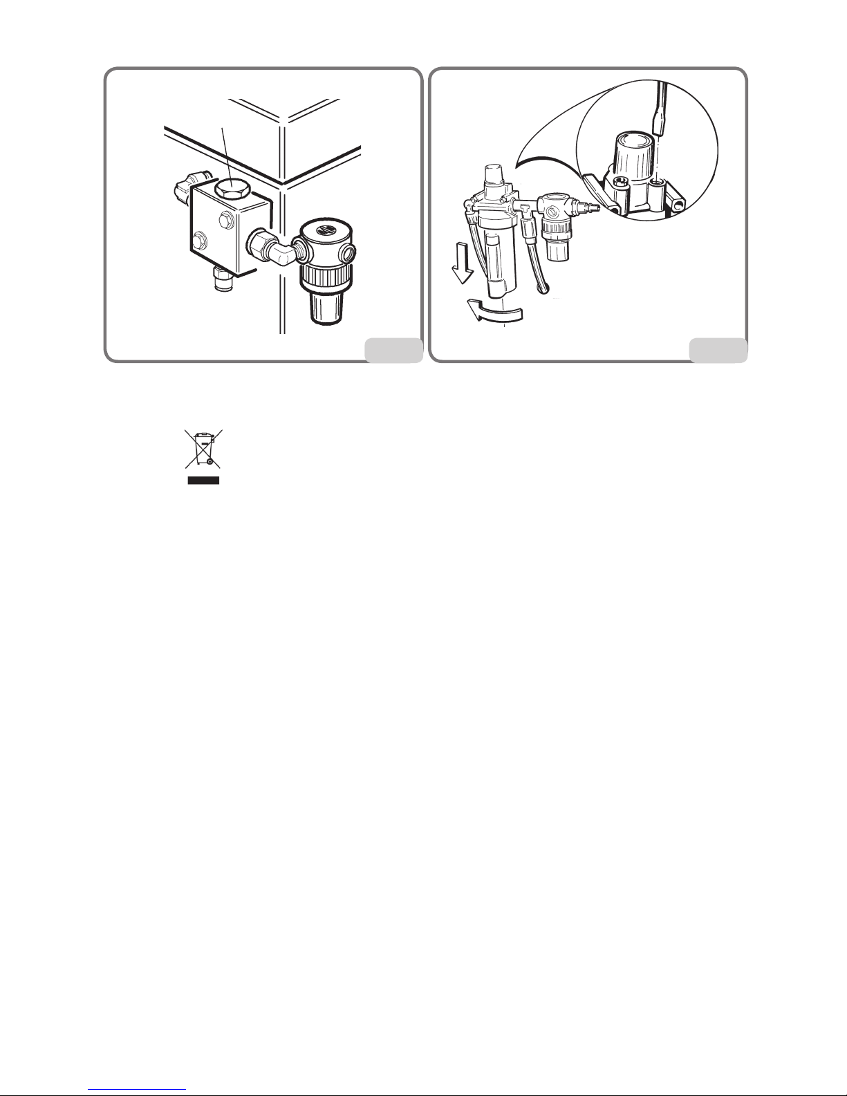
DANGER
When the machine is disconnected from the air supply system, the devices marked with the
warning sign shown above may remain pressurised.
- The lter+regulator+lubricator (Teco 27 Sp.) is equipped with a semiautomatic condensation drain
device. This device operates automatically whenever the compressed air supply to the machine
is cut off. Drain the condensation manually (push-button d, g 22 ) when the level exceeds the
mark X, g. 22.
- Clean the top plate of the turntable every week: remove any accumulated dirt and clean with
environmentally-friendly solvents.
- Monthly checks (Teco 25 - Teco 27 Sp.):
• Clean the arms of the tool-carrying head, the bead breaking unit and the relative travel screws
with environmentally-friendly solvents only. Lubricate.
• Check the oil level in the air lubricator (g. 22) and, if necessary, top up with non-detergent
SAE20 oil to the indicated level Z.
• Clean with a dry cloth. Avoid contact with solvents.
Page 23

User’s manual - TECO 22 - 23 - 25 - 27 Special 23
• Check the oil ow-rate through the transparent cover K (correct ow-rate: 1 drop of oil every
4 bead breaking cycles). Adjust if necessary by turning the set screw Y g. 22.
- Monthly checks (Teco 22 - Teco 23):
• Clean and lubricate with naphta the horizontal arm and mounting bar.
• Disconnect the machine from the pneumatic circuit.
• Remove cap 1 and let a few drops of non-detergent (SAE 20) in using an ampoule.
• put cap 1 back on and tighten rmly.
• Check the stretch of the motor/reduction gear driving belt; using the machine, such belt
may become loosen and worn out.
CAUTION
Keep the working area clean.
Never use compressed air, jets of water or solvent to remove dirt or deposits off the machine.
When cleaning, take care not to create and raise dust as far as possible.
22
a
b
c
e
d
x
Page 24
24 User’s manual - TECO 22 - 23 - 25 - 27 Special
ENVIRONMENTAL INFORMATION
The following disposal procedure shall be exclusively applied to the machines having the crossed-out
bin symbol
on their data plate.
This product may contain substances that can be hazardous to the environment or to human health
if it is not disposed of properly.
We therefore provide you with the following information to prevent releases of these substances and
to improve the use of natural resources.
Electrical and electronic equipment should never be disposed of in the usual municipal waste but
must be separately collected for their proper treatment.
The crossed-out bin symbol, placed on the product and in this page, remind you of the need to
properly dispose of the product at the end of its life.
In this way it is possible to prevent that a not specic treatment of the substances contained in these
products, or their improper use, or improper use of their parts may be hazardous to the environment
or to human health. Furthermore this helps to recover, recycle and reuse many of the materials used
in these products.
For this purpose the electrical and electronic equipment manufacturers and dealers set up proper
collection and treatment systems for these products.
At the end of life of your product contact your dealer to have information on the collection arrangements.
When buying this new product your dealer will also inform you of the possibility to return free of
charge another end of life equipment as long as it is of equivalent type and has fullled the same
functions as the supplied equipment.
A disposal of the product different from what described above will be liable to the penalties prescribed
by the national provisions in the country where the product is disposed of.
We also recommend you to adopt further measures for environment protection: recycle the internal and
external packing of the product and properly dispose of dead batteries (if contained in the product).
With your help the amount of natural resources used to produce electrical and electronic equipment
can be reduced, the use of landlls for the disposal of the products, minimized, and the quality of life
improved by preventing that potentially hazardous substances are released into the environment.
23
1
TECO 22 -23
24
TECO 25
Page 25

User’s manual - TECO 22 - 23 - 25 - 27 Special 25
INFORMATION AND WARNINGS ABOUT OIL
Disposing of old oil
Do not dispose of used oil in sewers, storm drains, rivers or streams; collect it and consign it to an
authorized disposal company.
Oil spills or leaks
Contain the spilt product from spreading using soil, sand or any other absorbent material.
Degrease the contaminated area with solvents, taking care to disperse solvent fumes. The residual
cleaning material must be disposed of as prescribed by law.
Precautions for the use of oil
- Avoid contact with the skin.
- Do not allow oil mists to form or spread in the atmosphere.
- Observe the following elementary health precautions:
• protect against oil splashes (appropriate clothing, protective guards on machines);
• wash frequently with soap and water; do not use cleaners or solvents that can irritate your skin
or remove its natural protective oil;
• do not dry hands with dirty or greasy rags;
• change clothing if impregnated with oil, and in any case at the end of every working shift;
• do not smoke or eat with greasy hands.
- Also adopt the following preventive and protective equipment:
• gloves resistant to mineral oils, with lining;
• goggles, in case of splashes;
• aprons resistant to mineral oils;
• screens to protect against oil splashes.
Mineral oil: first aid procedures
- Swallowing: seek medical attention, providing the characteristics of the type of oil swallowed.
- Inhalation: in case of exposure to high concentrations of fumes or mists, take the affected person
to the open air and seek medical attention immediately.
- Eyes: rinse with plenty of running water and seek medical attention as soon as possible.
- Skin: wash with soap and water.
RECOMMENDED FIRE-EXTINGUISHING DEVICES
For guidance on the most suitable type of extinguisher, refer to the table below:
Dry mate-
rials
Flamma-
ble
liquids
Electrical
equip-
ment
Water YES NO NO
Foam YES YES NO
Powder YES* YES YES
CO
2
YES* YES YES
YES* Use only if more appropriate extinguishers are not at hand or when the re is small.
WARNING
This table contains general instructions intended to be used as guidelines for users. Contact
the manufacturer for details of the applications of each type of extinguisher.
Page 26

26 User’s manual - TECO 22 - 23 - 25 - 27 Special
GLOSSARY
Air delivery regulator: Union allowing regulation of the air ow.
Beading: Operation which takes place during ination and ensures perfect centring between the
bead and the rim edge.
Bead breaking: Operation in which the bead of the tyre is detached from the edge of the rim.
Bead pressing gripper: A tool intended for use when mounting the top bead. It is tted so that it
grips the shoulder of the rim and holds the tyre top bead inside the drop centre. It is generally used
for mounting low prole tyres.
Tubeless Inator: An ination system which simplies inating tubeless tyres.
Bead: The edge of the tyre that remains in contact with the rim when the tyre is installed.
Tubeless: A tyre without an inner tube..
TROUBLE SHOOTING
CAUTION
In case of unexpected failure, electrically insulate the machine by means of an omnipolar disconnection device.
Turntable not turning
Feeding plug not connected or defective.
- Check the plug.
Machine not powered.
- Restore the electric connections.
Defective inverter.
- Replace the inverter (skilled staff needed in this case).
Motor shorted.
- Replace the motor (skilled staff needed in this case).
Belt broken.
- Replace belt.
Rotation control pedal fails to return to central position
Control spring broken.
• Replace the control spring.
Bead breaker pedal and table top pedal do not return to home position
Control spring broken.
- Renew the spring.
No oil in lubricator.
- Top up lubricator with SAE20 non-detergent oil.
Air leak inside the machine
Air leak from bead breaker cock.
- Renew the cock.
- Renew bead breaker cylinder.
Air leak from the table top cock.
- Renew table top cylinder.
- Renew swivel connector.
Page 27

User’s manual - TECO 22 - 23 - 25 - 27 Special 27
Bead breaker cylinder lacks force, fails to break beads and leaks air
Silencer plugged.
- Renew silencer.
Cylinder seals worn.
- Renew seals.
- Renew bead breaker cylinder.
Bead breaker cylinder leaks air around the rod
Air gaskets worn.
- Replace gaskets.
- Replace bead breaker cylinder.
Table top will not rotate in either direction
Inverter faulty.
- Replace inverter.
Belt broken.
- Renew belt.
Gear unit broken.
- Renew gear unit.
Gear unit noisy. The table top makes 1/3 of a spin and then stops
Gear unit seizing.
- Replace gear unit.
Table top fails to clamp wheels
Table top does not clamp rim.
- Renew table top cylinder.
Table top mounts or demounts wheels with difficulty
Insufcient belt tension.
- Adjust tension or replace belt.
Tyre pressure gauge needle fails to return to 0
Pressure gauge faulty or damaged.
- Replace pressure gauge.
WARNING
The “Spare parts” handbook does not authorize users to carry out work on the machine
with the exception of those operations expressly described in the user manual. It only
enables users to provide the technical assistance service with precise information in order
to minimize delays.
Page 28

28 User’s manual - TECO 22 - 23 - 25 - 27 Special
1
3 5
7
9 11
2
4
6
8
10 12
0
RL
3 Ph ~
L2
L3
PE
XS1
SPINA E PRESA
Plug & Socket
INVERTITORE COMMUTATORE DI POLARITA’
Reverse Polarity Switch
x 11-12
x 9-10
x 7-8
x 5-6
x 3-4
x 1-2
L 0 R
1
2
3
L1
ELEMENTI - Elements
CONTATTI - Contacts
W2
U1
U2
V2
V1
W1
W2
U1
U2
V2
V1
W1
200-220-240V
380-415-440V
MORSETTIERA Junction Box
F
F
F
Power
Phase
400V / 3 / 50 Hz - 0,55 kW 500V, 4A
400V / 3 / 50 Hz - 0,75 kW 500V, 6A
230V / 3 / 50 Hz - 0,55 kW 250V, 10A
230V / 3 / 50 Hz - 0,75 kW 250V, 10A
200V / 3 / 50 Hz - 0,75 kW (Japan) 250V, 10A
F: Fuse
Page 29

User’s manual - TECO 22 - 23 - 25 - 27 Special 29
1
3 5
7
9 11
2
4
6
8
10 12
0
RL
1 Ph ~
C
L1
N
PE
XS1
SPINA E PRESA
Plug & Socket
INVERTITORE COMMUTATORE DI POLARITA’
Reverse Polarity Switch
x 11-12
x 9-10
x 7-8
x 5-6
x 3-4
x 1-2
L 0 R
1
2
3
ELEMENTI - Elements
CONTATTI - Contacts
F
F
Power
Phase Neutral
230V / 1 / 50 Hz 250V, 16A 250V, 16A
240V / 1 / 50 Hz 250V, 16A 250V, 16A
220V / 1 / 60 Hz 250V, 16A 250V, 16A
115V / 1 / 60 Hz 250V, 20A 250V, 20A
F: Fuse
W2
U1
U2
V2
V1
W1
C
8
12
3
2
MORSETTIERA Junction Box
Page 30

30 User’s manual - TECO 22 - 23 - 25 - 27 Special
0
R
L1
3 Ph ~
L2
L3
PE
XS1
SPINA E PRESA
Plug & Socket
INVERTITORE COMMUTATORE DI POLARITA’
Reverse Polarity Switch
L1
ELEMENTI - Elements
CONTATTI - Contacts
1
3 5
7
9 11
2
4
6
8
10
12
13
15
17 19 21 23
14
16
18
20
22 24
L2
23-24
x
x x 21-22
x 19-20
x 17-18
x x 15-16
x x 13-14
x 11-12
x 9-10
x 7-8
x x 5-6
x x 3-4
x 1-2
L2 L1 0 R
1
2
3
4
5
6
V2U2W2
W1
V1
U1
PE
22
13
15
24
9
11
F
F
F
Power
Phase
400V / 3 / 50 Hz 500V, 6A
230V / 3 / 50 Hz 250V, 16A
400V / 3 / 60 Hz 500V, 6A
230V / 3 / 60 Hz 250V, 12A
F: Fuse
28
Page 31

User’s manual - TECO 22 - 23 - 25 - 27 Special 31
29
REF. DESCRIZIONE DESCRIPTION
01 INNESTO RAPIDO MASCHIO QUICK UNION
02 GRUPPO FRL WATER SEPARATOR AND PRESSURE REGUL+LUBRIFICATOR
03 VALVOLA GONFIAGGIO RAPIDO QUICK INFLATING VALVE
04 PISTOLETTA DI GONFIAGGIO INFLATING GUN AND GAUGE
05 VALVOLA STALLONATORE BEAD BREAKING VALVE
06 VALVOLA SCARICO RAPIDO QUICK DISCHARGED VALVE
07 CILINDRO STALLONATORE BEAD BREAKING CYLINDER
08 VALVOLA AUTOCENTRANTE SELF-CENTERING CHUCK VALVE
09 RACCORDO GIREVOLE ROTATING UNION
10 CILINDRO AUTOCENTRANTE SELF-CENTERING CHUCK CYLINDER
11 VALVOLA DI GONFIAGGIO INFLATING VALVE
12 VALVOLA A MEMBRANA VALVE
13 VALVOLA DI SICUREZZA SAFETY VALVE
14 UNITA’ DI GONFIAGGIO INFLATE UNION BOX
8-16 bar
MAX 10 bar
01
02
03
04
05
06
07
08
09
10
10
SCHEMA PNEUMATICO STD
Pneumatic STD Diagram
8-16 bar
MAX 10 bar
MAX 11 bar
01
02
03
11
05
06
07
08
09
10
10
SCHEMA PNEUMATICO T.I.
Pneumatic T.I. Diagram
12
13
14
09
Page 32

EC DECLARATION OF CONFORMITY
WE,
Teco Srl
Via Pio La Torre 10
42015 Correggio (RE)
Italy,
DECLARE UNDER OUR SOLE AND EXCLUSIVE RESPONSIBILITY THAT THE MACHINE:
TYPE:
tyre changer
MODEL:
SERIAL No.:
serial number
TO WHICH THIS STATEMENT REFERS AND FOR WHICH WE HAVE PREPARED AND HOLD THE RELATIVE TECHNICAL BOOKLET, COMPLIES WITH THE BASIC REQUISITES DEFINED BY THE FOLLOWING EUROPEAN UNION
DIRECTIVES:
- 2006/42/EC;
- 2014/35/EU;
- 2014/30/EU;
- 2011/65/EU;
- 2014/29/EU*.
*Only valid for the version with T.I.
THE FOLLOWING HARMONISED STANDARDS HAVE BEEN APPLIED TO VERIFY COMPLIANCE WITH THE FOLLOWING DIRECTIVES:
EN ISO 12100:2010; EN 60204-1:2006/AC:2010; EN 61000-6-2:2005/AC:2005;
EN 61000-6-3:2007/A1:2011/AC:2012
Correggio, 01/04/2016
TECHNICAL DIRECTOR
Ing. Mauro Barbetti
THE TECHNICAL DOSSIER RELATIVE TO CONSTRUCTION WILL BE KEPT AND WILL BE RENDERED AVAILABLE
BY ING. MAURO BARBETTI, C/O TECO SRL, VIA PIO LA TORRE , 10 42015 CORREGGIO (RE) ITALY.
IMPORTANT:THIS DECLARATION SHALL NO LONGER APPLY IF CHANGES ARE MADE TO THE PRODUCT WITH
RESPECT TO ITS CONFORMATION AT THE TIME OF SALE OR IF CHANGES ARE MADE TO THE COMPONENTS
WITHOUT THE PRIOR AUTHORIZATION OF THE MANUFACTURER, OR IN THE CASE OF NON-COMPLIANCE
WITH THE INFORMATION CONTAINED IN THE USER MANUAL.
THE MODEL FOR THIS DECLARATION COMPLIES WITH WHAT IS SET FORTH IN EN ISO/IEC 17050-1 AND EN
ISO/IEC 17050-2
Page 33

Page 34

Page 35

Page 36

Automotive Equipment
Teco Srl - Via Pio La Torre, n°10
42015 Correggio (RE) Italy
www.teco.it - www.tecorus.ru
www.youtube.com/user/TECOsrl
Telephone: +39.0522.631562
Fax: +39.0522.642373
E-mail: teco@teco.it
 Loading...