

SERVICE Manual
RANGE HOOD CONTENTS
• Safety precautions
• Distance from the hob
• Technical specications
• Technical data
• Parts supplied
• Non-return valve - parts supplied
• Aluminium panel / charcoal lter
• Installation
• Control drawing
• Touch control
• Bulbs
• Transformer
• Power board
• Electrical assembly
• Motor
• Condenser
• Wiring diagram
• Exploded view
• Spare parts list
• Troubleshooting
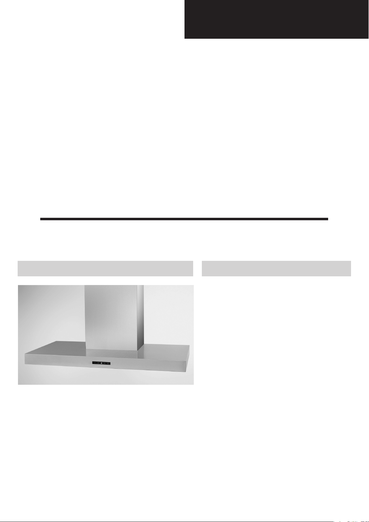
Model:
EAGLE


SUMMARY
1. Safety precautions.....................................................................................................................................................................4
2. Distance from the hob.........................................................................................................................................................7
3. Technical specifications.........................................................................................................................................................8
4. Technical data............................................................................................................................................................................9
5. Parts supplied .......................................................................................................................................................................10
6. Non-return valve - parts supplied .....................................................................................................................................11
7. Aluminium panel / charcoal filter .......................................................................................................................................12
7.1 replacing the aluminum panel
7.2 replacing the charcoal filter
8. Installation...................................................................................................................................................13
8.1 fixing the appliance to a wall
8.2 fixing the decorative telescopic flue
8.3 installing the charcoal filters and aluminum panels
9. Control drawing......................................................................................................................................................................19
9.1 configuration
9.2 technical drawing of control board
10. Touch control............................................................................................................................................................................21
10.1 replacing the touch control
11. Bulbs.............................................................................................................................................................................................23
11.1 replacing the halogen bulbs
11.2 replacing the halogen bulbs socket
12. Transformer................................................................................................................................................................................26
12.1 replacing the transformer
13. Power board...............................................................................................................................................................................29
13.1 replacing the power board
14. Electrical assembly.................................................................................................................................................................31
15. Motor.............................................................................................................................................................................................32
15.1 replacing the motor
16. Condenser...................................................................................................................................................................................37
16.1 replacing the condenser
17. Wiring diagram.........................................................................................................................................................................40
18. Exploded view...........................................................................................................................................................................41
19. Spare parts list.....................................................................................................................................................................42
20. Troubleshooting.......................................................................................................................................................................43
- 3 -
Safety precautions
Before connecting the model to the electricity
network:
- Control the data plate (positioned inside the appliance)
to ascertain that the voltage and power correspond to
the network and the socket is suitable. If in doubt ask
a qualied electrician.
- If the power supply cable is damaged, it must be replaced with another cable or a special assembly, which
may be obtained direct from the manufacturer or from
the Technical Assistance Centre.
- This device must be connected to the supply network
through either a plug fused 3A or hardwired to a 2 fase
spur protected by 3A fuse.
WARNING !
In certain circumstances electrical appliances may
be a danger hazard.
A) Do not check the status of the filters while the
cooker hood is operating
B) Do not touch bulbs or adjacent areas, during or
straight after prolonged use of the lighting installation.
C) Flambè (Flamed) cooking is prohibited underneath the cooker hood
D) Avoid free flame, as it is damaging for the filters
and a fire hazard
E) Constantly check food frying to avoid that the
overheated oil may become a fire hazard
F) Disconnect the electrical plug prior to any maintenance.
G) This appliance is not intended for use by young
children or infirm persons without supervision
H) Young children should be supervised to ensure
they do not play with the appliance
I) There shall be adequate ventilation of the room
when the rangehood is used at the same time as
appliances burning gas or other fuels
L) There is a risk of fire if cleaning is not carried out
in accordance with the instructions
M) Please use a private plug receptacle for power
plug.
: It might set a fire.
N) Please don’t operate the hood when taking fire
on the dishes or frying pan.
: It might set a fire.
O) Please don’t touch the product or operate the
switch with wet hands.
: You might get a shock of electricity.
P) Please don’t wipe off the hood with the chemi-
cals when cleaning.
This appliance conforms to the European Directive
EC/2002/96, Waste Electrical and Electronic Equipment (WEEE). By making sure that this appliance is
disposed of in a suitable manner, the user is helping
to prevent potential damage to the environment or to
public health.
The symbol on the product or on the accompanying paperwork indicates that the appliance
should not be treated as domestic waste, but
should be delivered to a suitable electric and electronic appliance recycling collection point. Follow local guidelines when disposing of waste. For more information on the treatment, re-use and recycling of
this product, please contact your local authority, domestic waste collection service or the shop where the
appliance was purchased.
Assembly and electrical connections must be carried out by specialised personnel.
• Electric Connection
The appliance has been manufactured as a class II,
therefore no earth cable is necessary.
The connection to the mains is carried out as follows:
BROWN = L line
BLUE = N neutral
If not provided, connect a plug for the electrical load
indicated on the description label. Where a plug is
provided, the cooker hood must be installed in order
that the plug is easily accessible. An omnipolar switch
with a minimum opening of 3mm between contacts,
in line with the electrical load and local standards,
must be placed between the appliance and the network in the case of direct connection to the electrical
network.
Before proceeding with the assembly operations, remove the anti-grease filter(s) so that the unit is easier
to handle. In the case of assembly of the appliance in
the suction version prepare the hole for evacuation of
the air.
• We recommend the use of an air exhaust tube which
has the same diameter as the air exhaust outlet hole.
If a pipe with a smaller diameter is used, the efficiency
of the product may be reduced and its operation may
become noisier.
- 4 -
Safety precautions
• We recommend that the cooker hood is switched on
before any food is cooked. We also recommend that
the appliance is left running for 15 minutes after the
food is cooked, in order to thoroughly eliminate all
contaminated air.
The effective performance of the cooker hood depends on constant maintenance; the anti-grease filter
and the active carbon filter both require special attention.
• The anti-grease filter is used to trap any grease particles suspended in the air, therefore is subject to saturation (the time it takes for the filter to become saturated depends on the way in which the appliance is
used).
- To prevent potential re hazards, the anti-grease lters
should be washed a minimum of every 2 months (it is
possible to use the dishwasher for this task).
- After a few washes, the colour of the lters may change.
This does not mean they have to be replaced.
If the replacement and washing instructions are not followed, the anti-grease lters may present a re hazard.
detergent.
CAUTION!
Wear gloves during the installation of the product otherwise injury at ngers could happen by sharp edges.
• The acrylic filter, which is found resting on the grille,
should be replaced when the text, visible through the
grille, changes colour and the ink spreads; the new fil-
ter should be fitted in such a way that the text can be
seen through the grille from outside the cooker hood.
• If the filters do not have any text on them, or if metal
filters or aluminium panel filters are used, they should
be washed every 2 months in order to prevent the risk
of fire.
To wash the filters, proceed as follows:
- Remove the filter from the grille and wash it using a
solution of water and neutral liquid detergent, leaving
the dirt to soften.
- Rinse thoroughly with warm water and leave to dry.
• The active carbon filters are used to purify the air
which is released back into the room. The filters are
not washable or re-usable and must be replaced at
least once every four months. The active carbon filter
saturation level depends on the frequency with which
the appliance is used, the type of cooking performed
and the regularity with which the anti-grease filters
are cleaned.
• Remove build-up from the fan and other surfaces
of the cooker hood regularly using a cloth moistened
with denatured alcohol or non-abrasive neutral liquid
- 5 -
Safety precautions
WARNING !
• Take care when the cooker hood is operating simultaneously with an open fireplace or burner that depend
on the air in the environment and are supplied by other than electrical energy, as the cooker hood removes
the air from the environment which a burner or fireplace need for combustion. The negative pressure in the
environment must not exceed 4Pa (4x10⁻⁵ bar). Provide adequate ventilation in the environment for a safe
operation of the cooker hood. Follow the local laws applicable for external air evacuation.
- 6 -
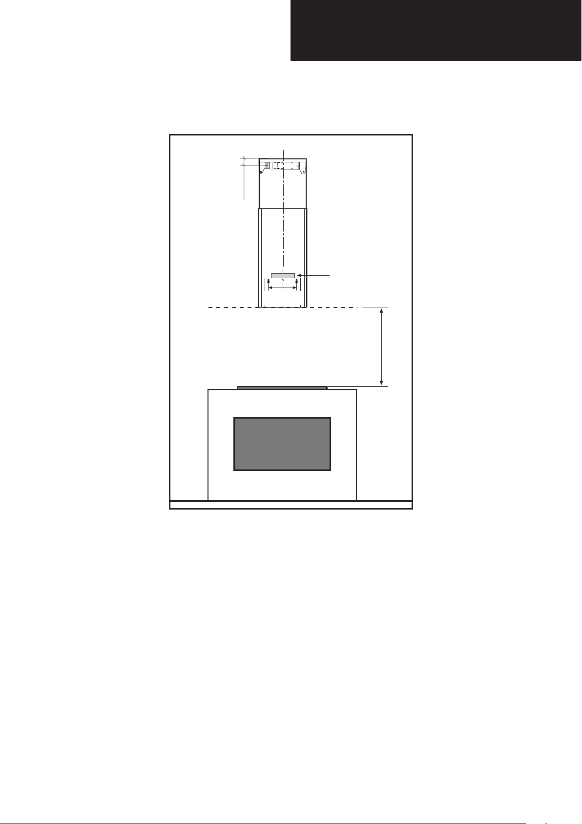
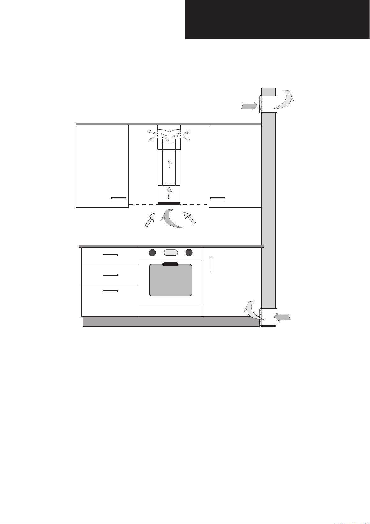
Distance from the hob
• The minimum distance between the support surfaces of the cooking pots on the cooker top and the lowest part
of the cooker hood must be at least 650 mm.
If a connection tube composed of two parts is used, the upper part must be placed outside the lower part.
Do not connect the cooker hood exhaust to the same conductor used to circulate hot air or for evacuating fumes
from other appliances generated by other than an electrical source.
- 7 -
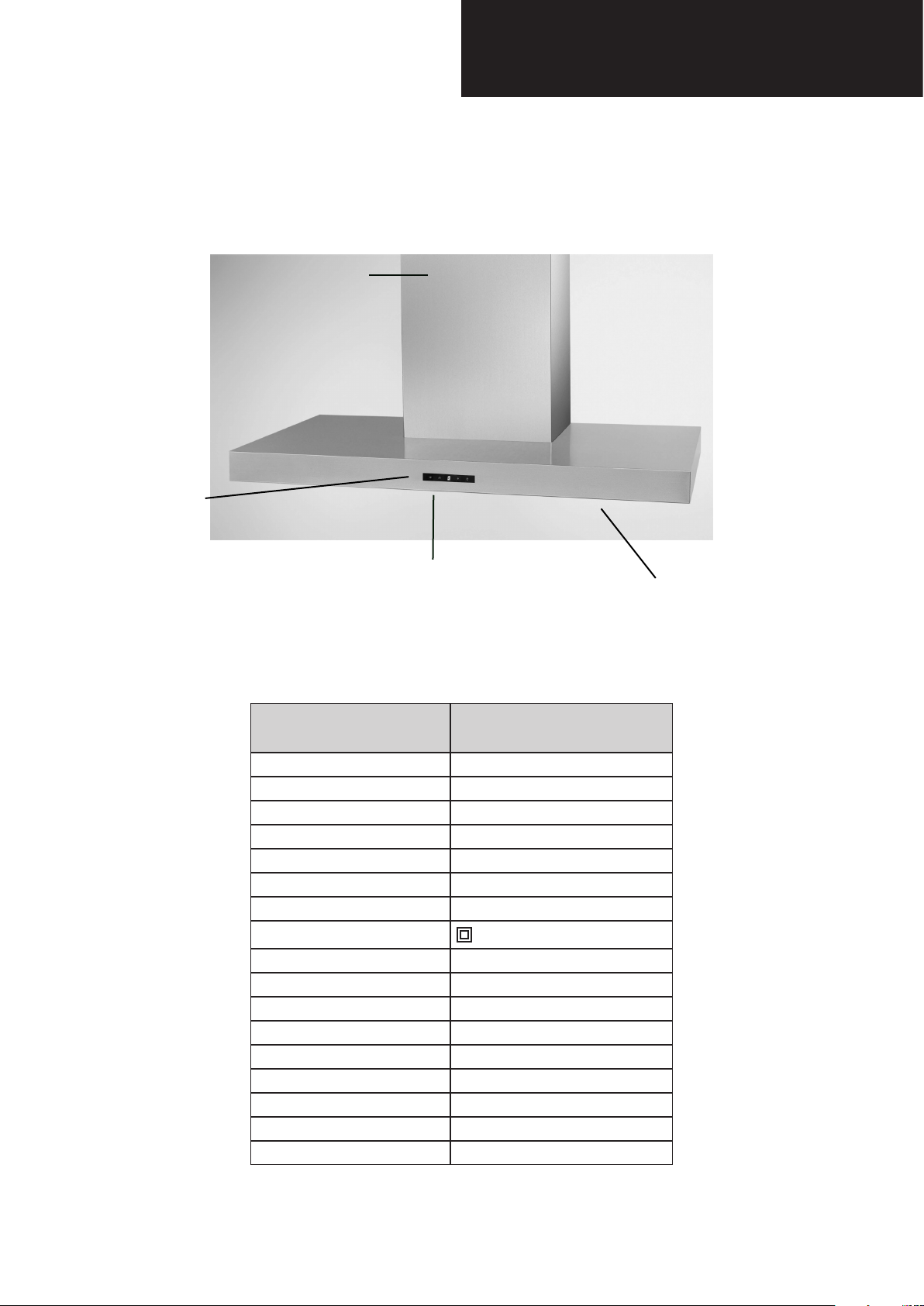
CONTROLS
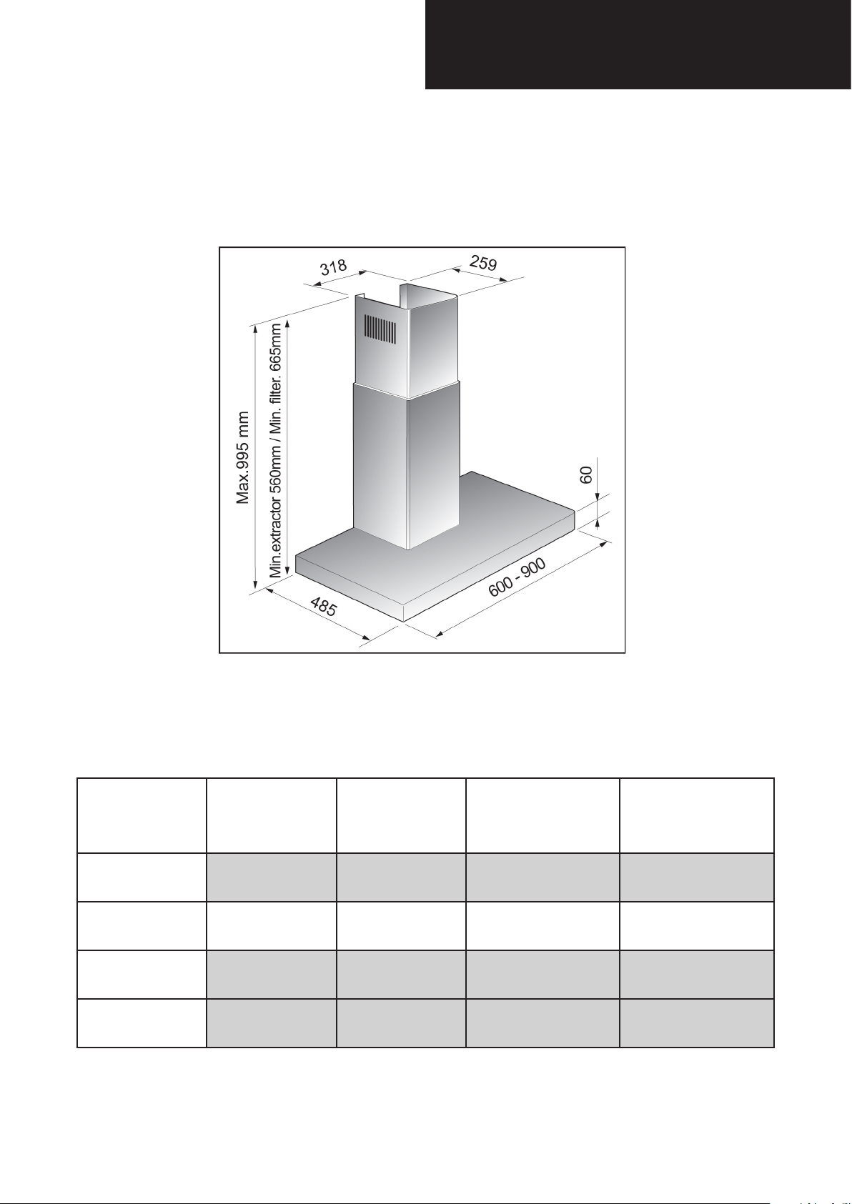
Technical specications
DUCTS
ALUMINIUM PANELS
MODEL
Size 600-900 mm
Finish St.steel A430
Motor JC2
Extracting power (m³/h) 500
Voltage 220-240V ~ 50/60Hz
Motor power consumption 1 x 130 W
Product certication CE - NEMKO
Product class II
Type model TYPE TOP..... MODEL:1J2HE
Air outlet diameter (mm) 150
Controls Touch Control
Speeds 3+1
Version Recycling
Filters Aluminium panels
Charcoal Filters 2 Circular lters
Bulbs 2 x 20 W Halogen lamps
Weight Gross 13,6 - 16 Kg
EAGLE
LIGHT
- 8 -
Technical data
motor power consumption 130 W
Speed
Suction
(m³/h)
Pressure
(Pa)
Noise Level
(sound pressure)
dBA
Noise Level
(sound power)
1 172 135 34 44
2 279 213 44 54
3 380 257 52 62
4 500 286 57 67
- 9 -
dBA
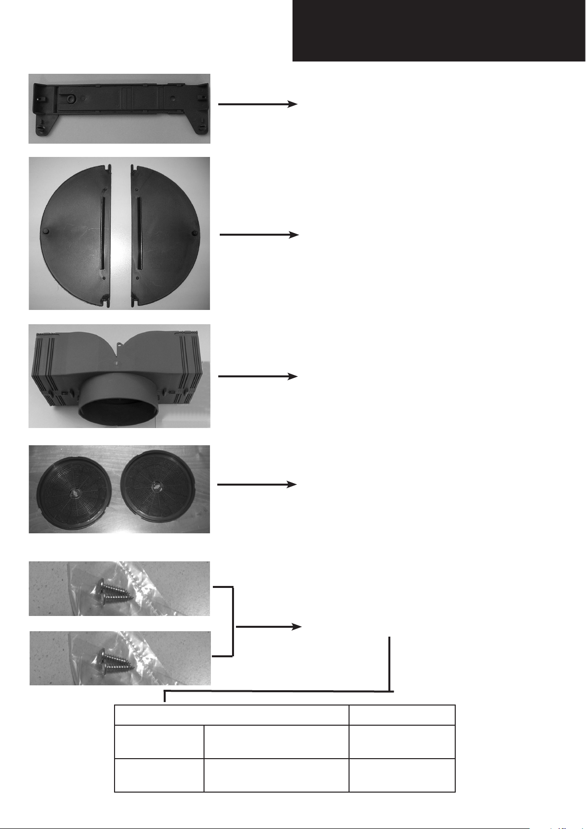
Parts supplied
CHIMNEY BRACKET
NON RETURN VALVE
AIR DEVIATOR
2 CHARCOAL FILTERS
MOUNTING SCREWS
3,2x13
3,5x6
TYPE INSERT
self-tapping screw
self-tapping screw
- 10 -
Pz 2
Pz 2
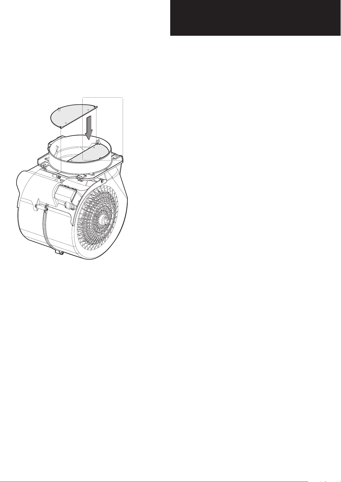
Non-return valve
parts supplied
The non-return valve is recommended when the appliance is installed in the extracting version, to prevent
cold air blowing back in from outside.
The valve is made up of two parts which must be fixed
to the air outlet flange on the motor assembly
If the appliance is installed in the filtering version, the
non-return valve is not necessary.
- 11 -
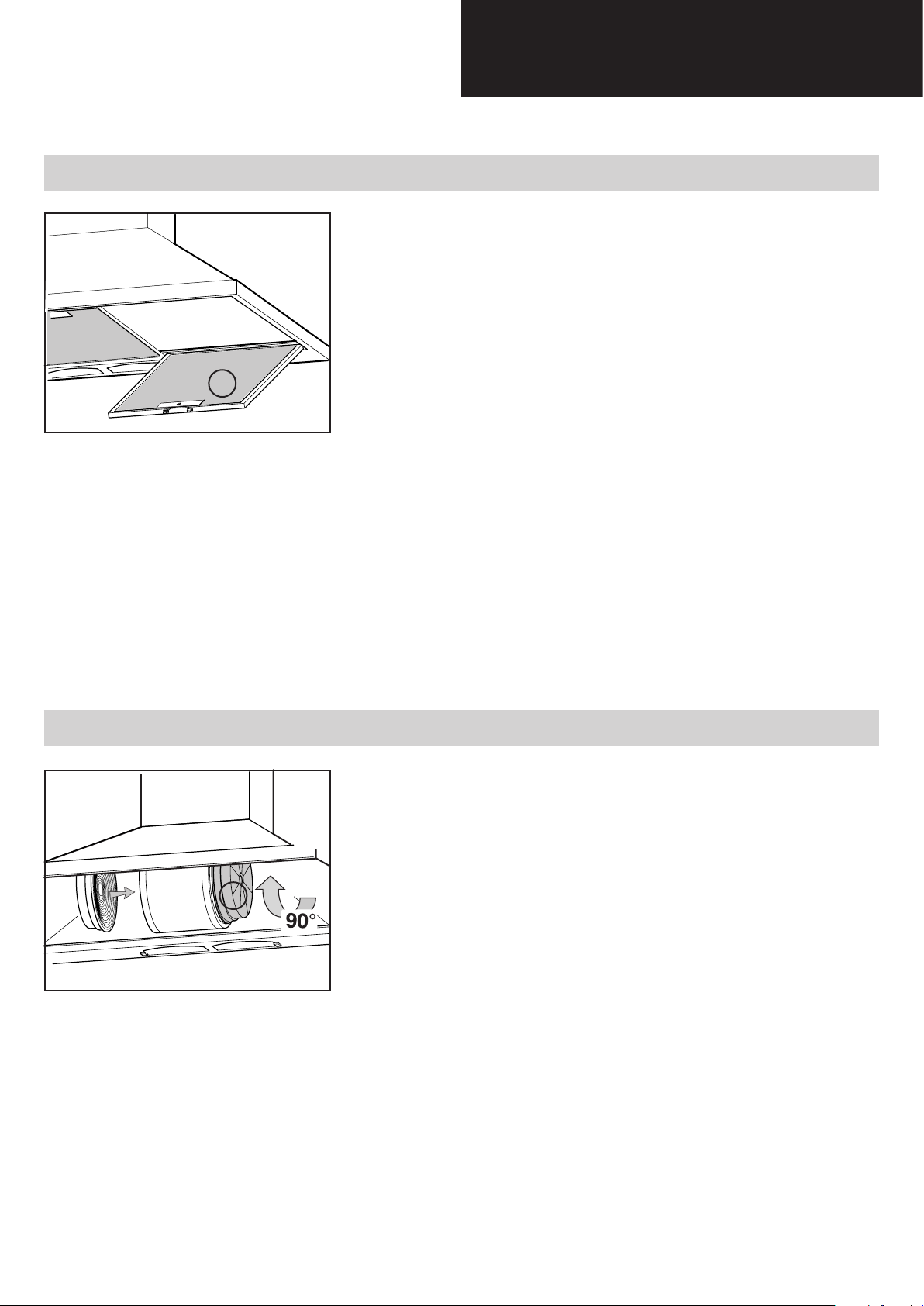
Aluminium panel
Replacing the aluminium panel (a) 7.1
The metal filters and/or aluminium panel are also dishwasher
safe. If the filters are made using aluminium, or if an aluminium
panel is used, after a few washes the colour may change. This
does not mean they have to be replaced.
If the replacement and washing instructions are not followed, the
anti-grease filters may present a fire hazard.
Charcoal lter
a
To replace the aluminium panels, simply operate the handle (a)
provided for the purpose, as illustrated in the drawing.
Replacing the charcoal lter (b) 7.2
The active carbon filters are used to purify the air which is released back into the room. The filters are not washable or re-usable
and must be replaced at least once every four months. The active carbon filter saturation level depends on the frequency with
b
which the appliance is used, the type of cooking performed and
the regularity with which the anti-grease filters are cleaned.
To replace the active charcoal filters, simply operate the handle
provided for the purpose, as illustrated in the drawing.
- 12 -
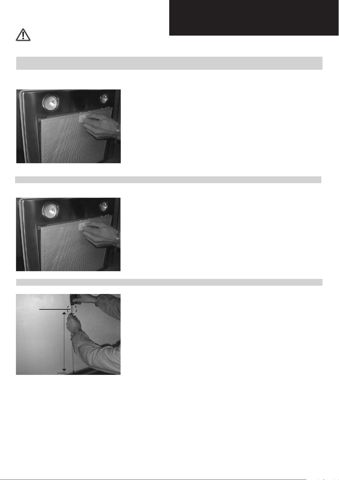
Installation
CAUTION!
Wear gloves during the installation of the product otherwise injury at ngers could happen by sharp edges.
Fixing the appliance to a wall 8.1
Before starting to fix the hood, disconnect the anti-grease
filter for easier appliance handing. Before this operation, perform
the following steps:
Phase 1
Phase 2
650 mm
Phase 1
- Pull handle as shown in the picture and remove the anti-grease
filter.
Phase 2
- Check the distance between the surface which carries the cooking utensils on the cooking device and the bottom surface of
the cooker hood, which must be not less than 650 mm. Mark the
position of the lower side of the hood on the wall.
- 13 -
Phase 3
Phase 4
Installation
Phase 3
- Drill the holes A respecting the distances indicated. Fix the appli-
ance to the wall and align it in horizontal position to the wall units.
Phase 4
- When the appliance has been adjusted, definitely fix the hood
using the screws A. For the various installations use screws and
screw anchors suited to the type of wall (e.g. reinforced concrete,
plasterboard, etc.). If the screws and screw anchors are provided
with the product, check that they are suitable for the type of wall
on which the hood is to be fixed.
The hood is now fixed to the wall.
- 14 -
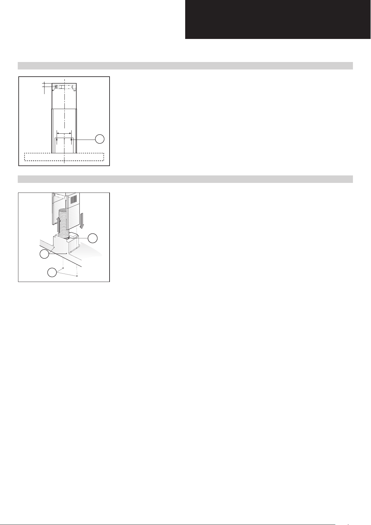
Phase 1
A
Installation
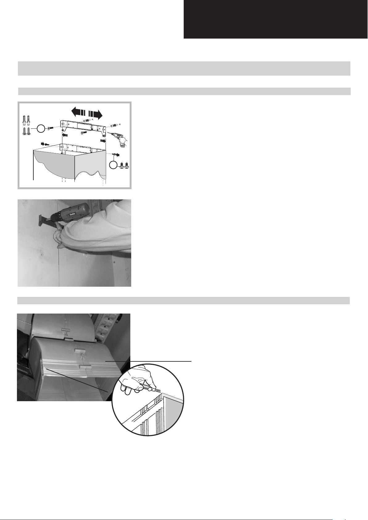
Fixing the decorative telescopic ue 8.2
Phase 1
- Arrange the electrical power supply within the dimensions of
the decorative ue. If your appliance is to be installed in the ducting version or in the version with external motor, prepare the air
exhaust opening.
Phase 2
B
- Adjust the width of the support bracket of the upper ue.
- Then x it to the ceiling using the screws A in such a way that it is
in line with your hood and respecting the distance from the ceiling.
Phase 2
- Cut the air deviator D with a cutter, following carefully the first
pre-cut starting from the outer edge on both sides, as indicated
in the picture.
Air deviator D
- 15 -

Phase 3
Installation
Phase 3
- Take the air deviator D and make two holes as shown in the photographs.
Ø 6
C
Phase 4
D
- Secure the duct fixing bracket to the air deviator D as shown in
the photograph.
C
D
Phase 4
- Carry out final fixing of the air deflector D to the wall with a
fixing screw as shown in the photograph.
D
- 16 -

Phase 5
Phase 6
Installation
Phase 5
- Connect the flexible pipe (not supplied) to the deviator D.
D
F
- Fix the flexible pipe onto the connector flange G.
G
Phase 7
Phase 6
- Take care not to scratch the duct; wear gloves when removing
the protective lm.
Phase 7
- Extend the upper decorative duct as far as bracket C and fix it in
place using screws X.
C
- 17 -

Phase 1
Installation
Installing the charcoal lters and aluminum panels 8.3
Phase 1
- Take the active charcoal filters and position them in their housings.
Phase 2
Phase 2
- Take the aluminum panels and position them in their housings.
- 18 -

Control drawing
Conguration 9.1
A = on/o lights switch
B = on/o cooker hood switch
C = indicates the motor speed level selected
D = switches on the cooker hood. Increases the motor speed
E = timer
- 19 -

Control drawing
Technical drawing of control board 9.2
- 20 -

Touch Control
Before carring out any kind of maintenance work, disconnect the appliance from the domestic electrical supply.
Replacing the touch control 10.1
Phase 1
Phase 1
- Disconnect the aluminium panels.
Phase 2
Phase 3
Phase 2
- Unscrew the screws as shown in the picture.
Phase 3
- Take away the control support.
Phase 4
Phase 4
- Disconnect the flat cable.
- 21 -

Phase 5
Phase 6
Touch Control
Phase 5
- Take away the control.
Phase 6
- Unscrew the two screws as shown in the picture.
Phase 7
Phase 7
- Replace the touch control.
- 22 -

Bulbs
Before carring out any kind of maintenance work, disconnect the appliance from the domestic electrical supply.
Replacing the halogen bulbs 11.1
Phase 1
- To replace the halogen bulbs B, remove the glass cover C using
a screw driver in the slots provided.
Replace the bulbs with new ones of the same type.
B
C
CAUTION!
Do not touch the bulb with bare hands.
- Put in completely when assemblying glass.
Note!
• The light on the cooker hood is designed for use during cooking and not for prolonged use for general room
illumination.
Prolonged use of the light considerably reduces the average life of the bulbs.
- 23 -

Phase 1
Phase 2
Bulbs
Replacing the halogen bulbs socket 11.2
Phase 1
- Disconnect the aluminium panels.
Phase 2
- Unscrew the screws as shown in the pictures
- 24 -

Phase 3
Phase 4
Bulbs
Phase 3
- Disconnect the two fast connector.
Phase 4
- Push the halogen bulb socket downwards and replace the bulbs
socket.
CAUTION!
Be careful because the lamp holder metal could be damaged by
pressure.
- 25 -

Transformer
Before carring out any kind of maintenance work, disconnect the appliance from the domestic electrical supply.
Replacing the Transformer 12.1
Before proceeding with replacement of the transformer, the following steps must be carried out:
- lift up the lower duct A
- secure the lower duct adequately with adhesive tape B to the
upper duct.
CAUTION!
Wear gloves during the installation of the product otherwise
injury at ngers could happen by sharp edges.
- 26 -

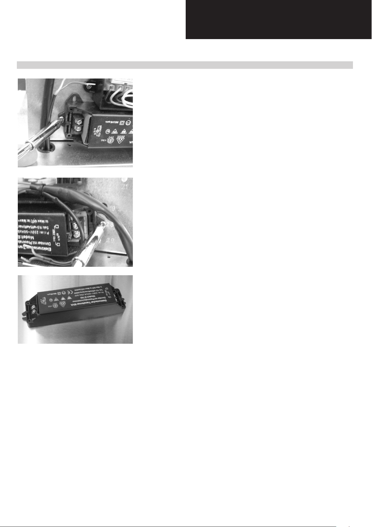
Phase 1
Transformer
Phase 1
- Unscrew the 4 screws as shown in the picture.
Phase 2
Phase 2
- Unscrew the 4 screws as shown in the picture and disconnect
the cables.
- 27 -
Phase 3
Transformer
Phase 3
- Unscrew the 2 screws. Now you can replace the transformer.
- 28 -

Power board
Before carring out any kind of maintenance work, disconnect the appliance from the domestic electrical supply.
Replacing the power board 13.1
Before proceeding with replacement of the power board, the following steps must be carried out:
- lift up the lower duct A
- secure the lower duct adequately with adhesive tape B to the
upper duct.
CAUTION!
Wear gloves during the installation of the product otherwise injury at ngers could happen by sharp edges.
- 29 -

Phase 1
Phase 2
Power board
Phase 1
- Unscrew the 5 screws as shown in the picture
Phase 2
- Disconnect the at cable and the electrical pins. Now you can
replace the power board.
ATTENTION!
during the reassembling phases be carefull because there is only
one correct way to connect the flat cable. All the electrical pins
must be reassembled in the right position. Refer to the wiring
diagram.
- 30 -

Electrical Assembly
- 31 -

Motor
Before carring out any kind of maintenance work, disconnect the appliance from the domestic electrical supply.
Replacing the motor 15.1
Before proceeding with replacement of the motor, the following
steps must be carried out:
- Remove the 2 srews B fixing the upper decorative duct A to the
wall fixing bracket C.
- Put the uyper decorative duct A inside the lower one D.
- Remove the 2 decorative ducts plaicing them on a level surface.
CAUTION!
1
Wear gloves during the installation of the product otherwise injury at ngers could happen by sharp edges.
B
3
C
A
2
B
4
D
- 32 -

Phase 1
Motor
Phase 1
- Unscrew the 2 screws as shown in the picture. And disconnect
the cables.
Phase 2
Phase 2
- Unscrew the 7 screws as shown in the picture, remove the motor
and place it on a solid surface.
- Cut the tie.
- 33 -

Phase 3
Phase 4
Motor
Phase 3
- Unscrew the 2 screws.
Phase 4
- Open the connector housing and disconnect the connector.
Phase 5
Phase 6
Be careful while you carry out this operation. Hold the motor
rmly.
Phase 5
- Remove the screws fixing the motor to the bracket and remove
the bracket from the motor.
Phase 6
- Remove all the screws indicated.
- 34 -

Motor
- 35 -

Phase 7
Phase 8
Motor
Phase 7
- Separate the RIGHT impeller housing from the LEFT
Phase 8
- Remove the plugs from the motor support.
Phase 9
Phase 9
- Remove the screws which secure the motor to the impeller housing.
- Replace the motor, unsoldering the electrical wires and resoldering them on the new motor
Please note!
To reassemble the parts, the operation must be carried out in reverse.
- 36 -

Condenser
Before carring out any kind of maintenance work, disconnect the appliance from the domestic electrical supply.
Replacing the condenser 16.1
Before proceeding with replacement of the condenser, the following steps must be carried out:
- Remove the 2 srews B fixing the upper decorative duct A to the
wall fixing bracket C.
- Put the uyper decorative duct A inside the lower one D.
- Remove the 2 decorative ducts plaicing them on a level surface.
CAUTION!
1
Wear gloves during the installation of the product otherwise injury at ngers could happen by sharp edges.
B
3
C
A
2
B
4
D
- 37 -

Phase 1
Phase 2
Condenser
Phase 1
- Remove the motor following the steps indicated in the previous
paragraph.
Phase 2
- Unscrew the tree screws as shown in the pictures.
- 38 -

Phase 3
Condenser
Phase 3
- Remove the plastic protection and disconnect the condenser.
Note!
This condenser is not polarized.
- 39 -

Wiring diagram
- 40 -

Model: EAGLE
Exploded view
- 41 -
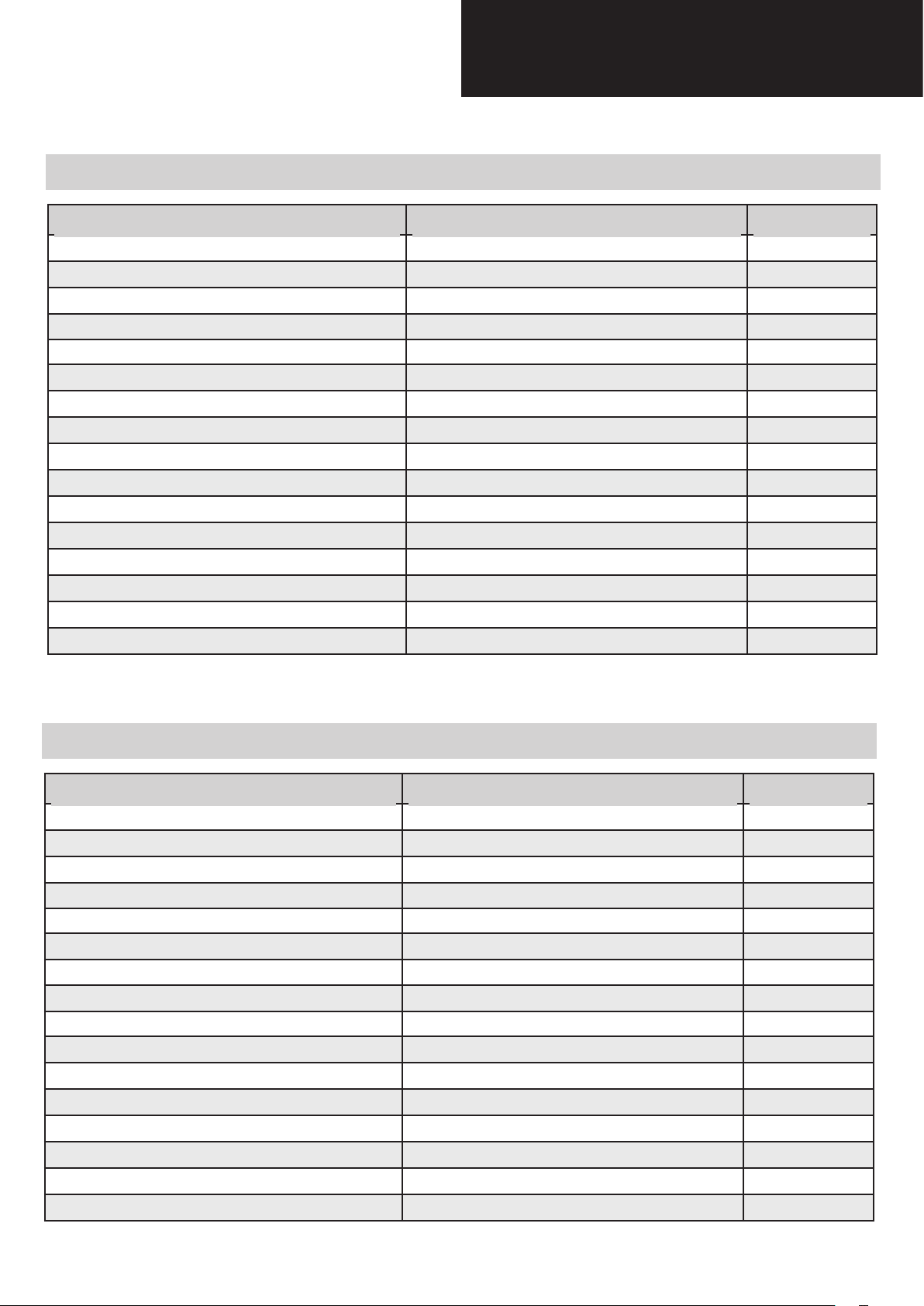
Spare parts list
Model: EAGLE 60
DESCRIPTION CUST CODE POSITION
ALUMINUM PANEL 29
CHIMNEY 30
CONVEYOR 39
FAN WHEEL 734
MOTOR 70
BODY 100
CONTROL 110
POWER CIRCUIT 120
MOTOR GROUP 140
SUPPORT 171
CONDENSER 261
BODY FOR TANGENTIAL MOTOR 469
TRANSFORMER 554
HALOGEN LAMP 609
CHIMNEY BRACKET 654
AIR DEVIATOR 656
Model: EAGLE 90
DESCRIPTION CUST CODE POSITION
ALUMINUM PANEL 29
CHIMNEY 30
CONVEYOR 39
FAN WHEEL 734
MOTOR 70
BODY 100
CONTROL 110
POWER CIRCUIT 120
MOTOR GROUP 140
SUPPORT 171
CONDENSER 261
BODY FOR TANGENTIAL MOTOR 469
TRANSFORMER 554
HALOGEN LAMP 609
CHIMNEY BRACKET 654
AIR DEVIATOR 656
- 42 -

Troubleshooting
ATTENTION!
1. The appliance has been manufactured as a class II therefore no earth cable is necessary.
2. Before carrying out any kind of maintenance job, disconnect the appliance from the domestic network supply.
3. Assembly and electrical connections must be carried out by specialized personnel.
Electrical Malfunction
SYMPTOM CAUSE CORRECTIONS
Complete appliance is not
working (lamps + unit motor)
Lamps are not working
Main network supply
Defective Connection of Power
supply cable
Defective Power supply cable Check if it’s damaged.
Defective Motor fast connection Check if it’s properly connected.
Defective Main Power Board
Defective Push Button Board
Defective Connections
Defective Lamps Replace lamps.
Defective Transformer Replace transformer.
Defective Main Power Board
Check if you have main network
supply in your house
- Check if it’s properly plugged
- Check if it’s properly
connected to the power socket
Check if it’s properly connected.
Replace Main Power Board
Check if it’s properly connected.
Replace Push Button Board
- Check lamp connection
- Check transformer connection
Check if it’s properly connected.
Replace Main Power Board
Motor or speeds are not
working
Control unit is not working
Defective Push Button Board
Defective Connections
Defective Main Power Board
Defective Push Button Board
Defective Condenser
Defective Motor unit Replace motor unit.
Defective Connections Check Connections
Defective Main Power Board
Defective Push Button Board
- 43 -
Check if it’s properly connected.
Replace Push Button Board.
Check motor control
connections
Check if it’s properly connected.
Replace Main Power Board
Check if it’s properly connected
Replace Main Power Board
- Check Connections
- Replace condenser
Check if it’s properly connected
Replace Main Power Board
Check if it’s properly connected
Replace Push Button Board.

3LIS0034
 Loading...