

Page 1

Battery BOX
ATA Energy Storage System MM
User’s Manual
Manuale Utente
Page 2

Page 3

Index - Indice
User’s Manual - English .......................................................................... 1
1 Safety Warnings .............................................................................. 1
1.1 Product Disposal .......................................................................... 1
1.2 Lead Batteries ............................................................................ 1
2 Mechanical Drawings for Battery Box 100Ah ........................................... 2
3 Mechanical Drawings for Battery Box 200Ah ........................................... 3
4 FBBATA48V1 and FBBATA48V2............................................................ 4
4.1 CONNECTION BATTERY 100Ah ........................................................ 5
4.2 CONNECTION BATTERY 200Ah ........................................................ 5
5 Box Battery Mounting Instructions ....................................................... 6
6 Connection with ATA ...................................................................... 11
Manuale Utente – Italiano ..................................................................... 12
1 Avvisi di Sicurezza ......................................................................... 12
1.1 Smaltimento del Prodotto ............................................................ 12
1.2 Batterie al Piombo ..................................................................... 12
2 Disegno Meccanico Box con Batterie 100Ah .......................................... 13
3 Disegno Meccanico Box con Batterie 200Ah .......................................... 14
4 FBBATA48V1 e FBBATA48V2 ............................................................. 15
4.1 CONNESSIONE BATTERIE 100Ah ..................................................... 16
4.2 CONNESSIONE BATTERIE 200Ah ..................................................... 16
5 Istruzioni Montaggio Box Batterie ...................................................... 17
6 Connessione con ATA ..................................................................... 22
© Copyright 2014 TECNOWARE s.r.l. All rights reserved.
All trademarks are property of their respective owners.
TECNOWARE s.r.l.
Via Montetrini, 2E – Molino del Piano – Florence – Italy
www.tecnoware.com
This manual has been printed and edited by TECNOWARE s.r.l.
February 2014 edition – version 1.0
Page 4

Page 5
User’s Manual - English
1 Safety Warnings
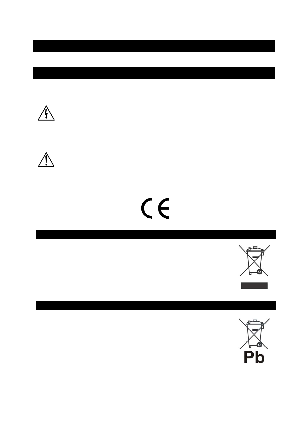
Risk of electric shock: if all the batteries are connected, inside the Battery Box there are
internal parts which are at a high Voltage and are potentially dangerous, capable of
causing injury or death by electric shock.
Any repair or maintenance work must be performed exclusively by qualified technical
personnel authorized by TECNOWARE. TECNOWARE declines any responsibility if this
warning is disregarded.
Danger of explosion and fire if the batteries of the wrong type or number are used.
Do not dispose of batteries in a fire. The batteries may explode. Do not open or mutilate
batteries. Released electrolyte is harmful to the skin and eyes. It may be toxic
The Battey Box is compliant with the European Community directives. Hence it is marked:
1.1 Product Disposal
This Battery Box cannot be disposed as an urban waste, but must be treated as a separate waste. Any
violation is indictable with financial sanctions as per in force regulations.
An incorrect waste disposal or an improper use of the same or of any parts can be damaging for the
environment and for human health.
A correct waste disposal of products having the dustbin symbol marked by a cross help to avoid
negative consequences to the environment and to human health.
1.2 Lead Batteries
The Battery Box may contain lead acid, sealed, maintenance free batteries.
This kind of batteries, if handled by non-experienced personnel, can cause electric shock or short-
circuit.
For this reason the batteries can be removed only by qualified technical personnel, specialized and
authorized by Tecnoware. Tecnoware declines any responsibilities if this rule is not followed.
The batteries cannot be disposed as an urban waste, but must be treated in conformity with
2006/66/CE European Directive; any violation is indictable with financial sanctions as established into
2006/66/CE European Directive.
Battery box for ATA Energy Storage System 1 User’s Manual
Page 6
cm
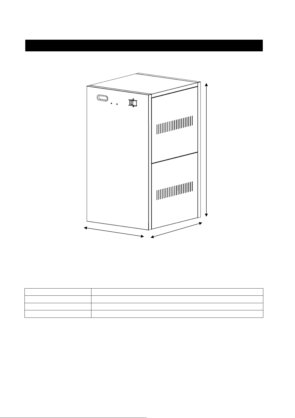
2 Mechanical Drawings for Battery Box 100Ah
71 cm
Dimension (W x H x D) (39.7 x 71 x 44.3) cm
Net Weight without Batteries 25 Kg
Batteries Number 4
Net Weight with Batteries 100Ah 155 Kg
39.7 cm
44.3
User’s Manual 2 Battery box for ATA Energy Storage System
Page 7
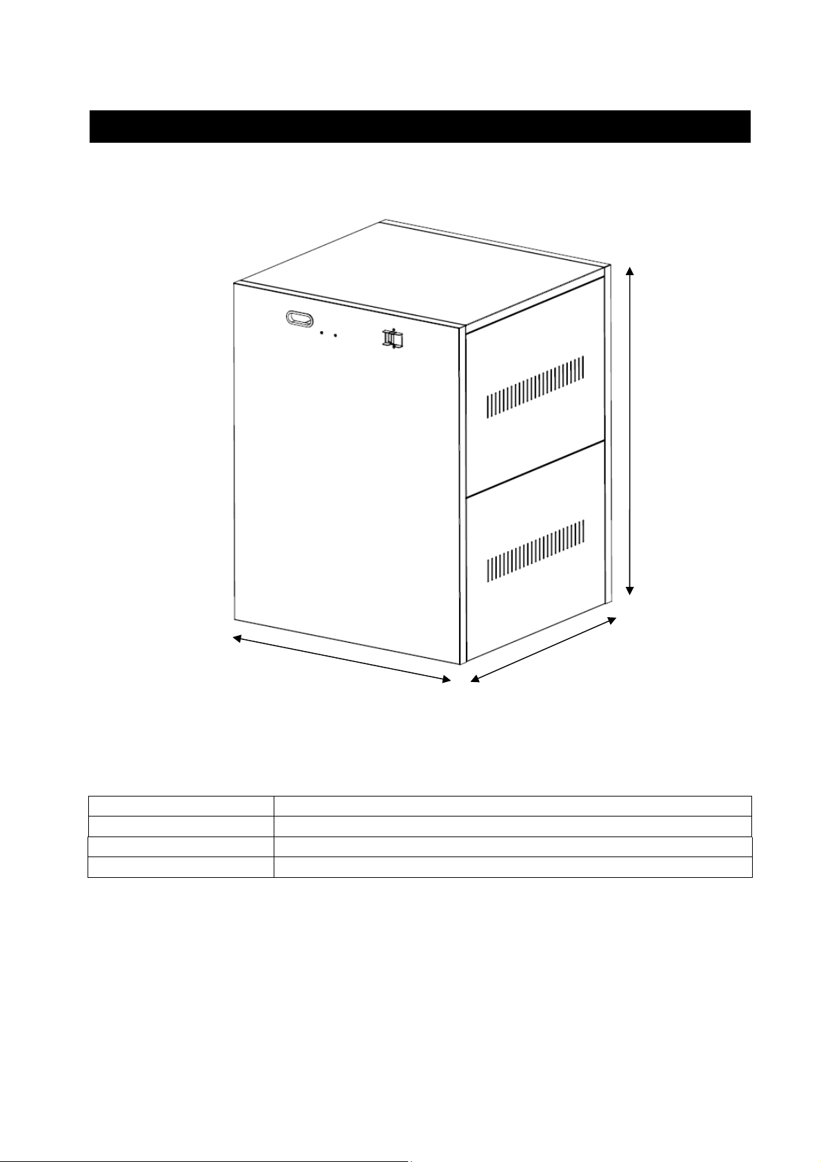
3 Mechanical Drawings for Battery Box 200Ah
76 cm
Dimension (W x H x D) (59.5 x 76 x 57.5) cm
Net Weight without Batteries 36 Kg
Batteries Number 4
Net Weight with Batteries 200Ah 300 Kg
59.5 cm
57.5cm
Battery box for ATA Energy Storage System 3 User’s Manual
Page 8
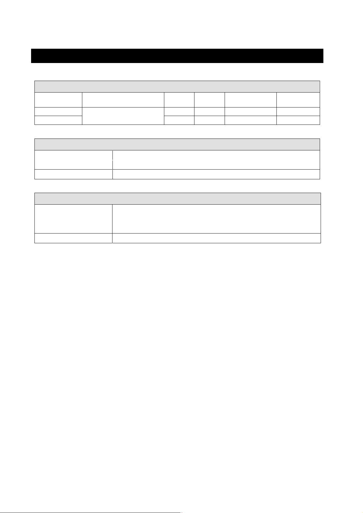
4 FBBATA48V1 and FBBATA48V2
MODELLI DISPONIBILI
Box Battery Code Description
FBBATA48V1/100
FBBATA48V2/200 4-5 KVA 200Ah 4 AWG (2 x 8 AWG) 125 A
Battery Box Compatible with ATA
Energy Storage System
ATA
Power
4-5 KVA 100Ah 4 AWG (2 x 8 AWG) 125 A
Battery
Capacity
Cables Section
BATTERIES
Battery Type Lead acid, sealed, free maintenance, 12 Vdc
Battery Number 1 x 4
Nominal Battery Voltage 48 Vdc
ENVIRONMENTAL CONDITIONS
Storage Temperature Range -25°C to +55°C (15°C to 30°C recommended for longer Battery life)
Operating Temperature Range 0°C to +40°C (20°C to 25°C recommended for longer Battery life)
Relative Humidity Range 0% - 95% (non condensing)
Max. Altitude without Derating 3000 meters
Breaker Max
Current
User’s Manual 4 Battery box for ATA Energy Storage System
Page 9
cm 25 cm
cm 38 cm
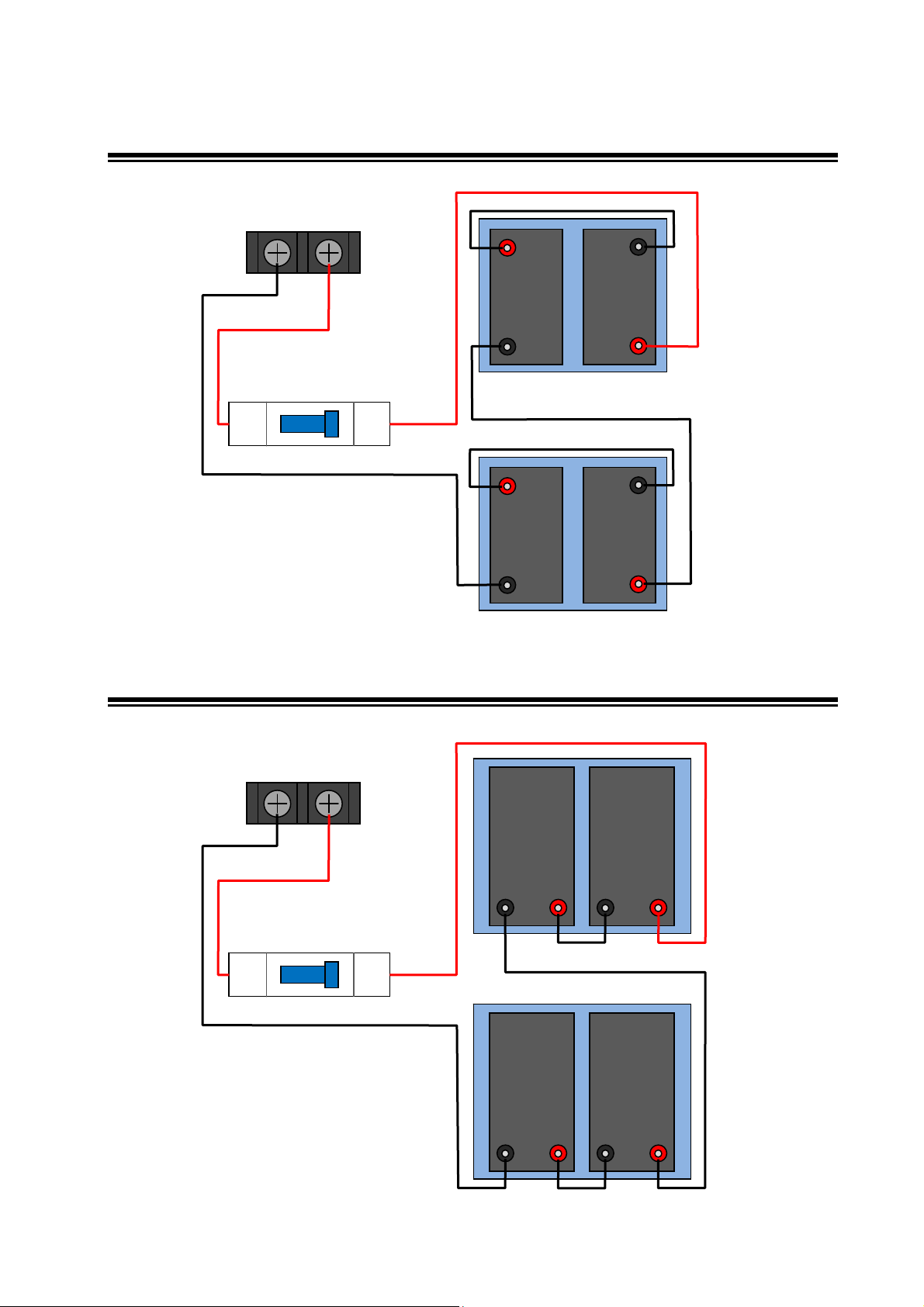
4.1 CONNECTION BATTERY 100Ah
+
TOP PART
38
-
48 cm
TERMINAL BLOCK
WITH BATTERY
CONNECTION
SECOND FLOOR
cm
14
-
+
BATTERY SELECTOR
OFF
ON
55 cm
-
FIRST
58 cm
-
+
BOTTOM PART
4.2 CONNECTION BATTERY 200Ah
TERMINAL BLOCK
WITH BATTERY
CONNECTION
16 cm
BATTERY SELECTOR
OFF
ON
70 cm
SECOND FLOOR
FIRST
-
-
TOP PART
+
25
+
60 cm
+
70 cm
+
-
-
BOTTOM PART
Battery box for ATA Energy Storage System 5 User’s Manual
Page 10
5 Box Battery Mounting Instructions
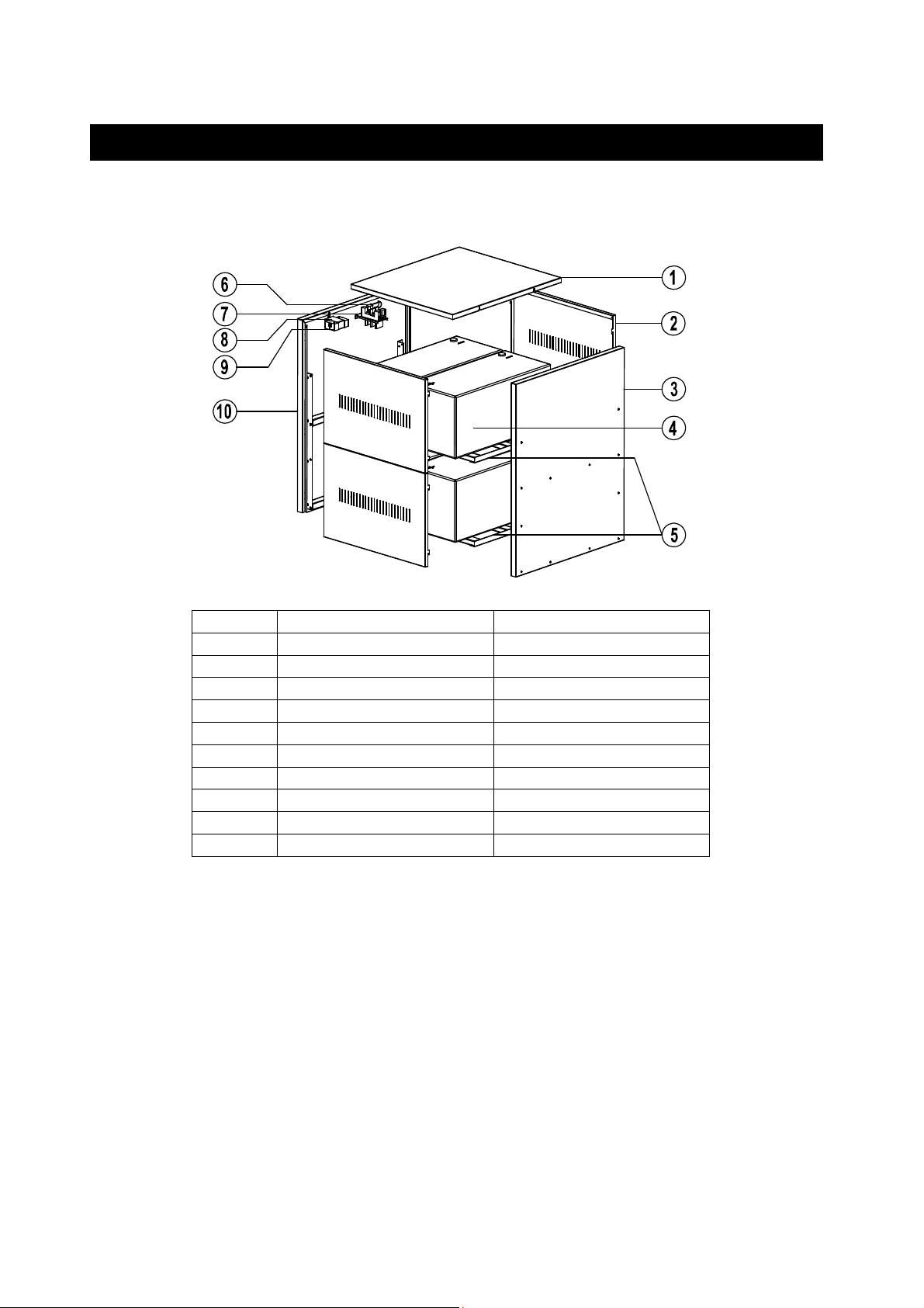
PACKING CONTENT:
Below is reported the packing content:
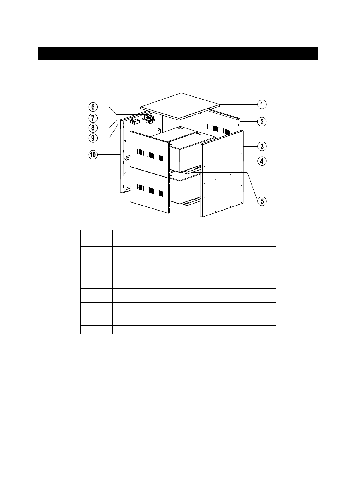
Item Description Quantity
1 Top case 1
2 Side case 4
3 Rear case 1
4 Battery packs * 4
5 Bracket 2
6 Battery terminal block 1
7 Connector fixing plate 1
8 U-type fixing plate 1
9 Breaker 1
10 Front case 1
*The batteries are not included with the battery box. There is the cable kit for battery
connection.
User’s Manual 6 Battery box for ATA Energy Storage System
Page 11
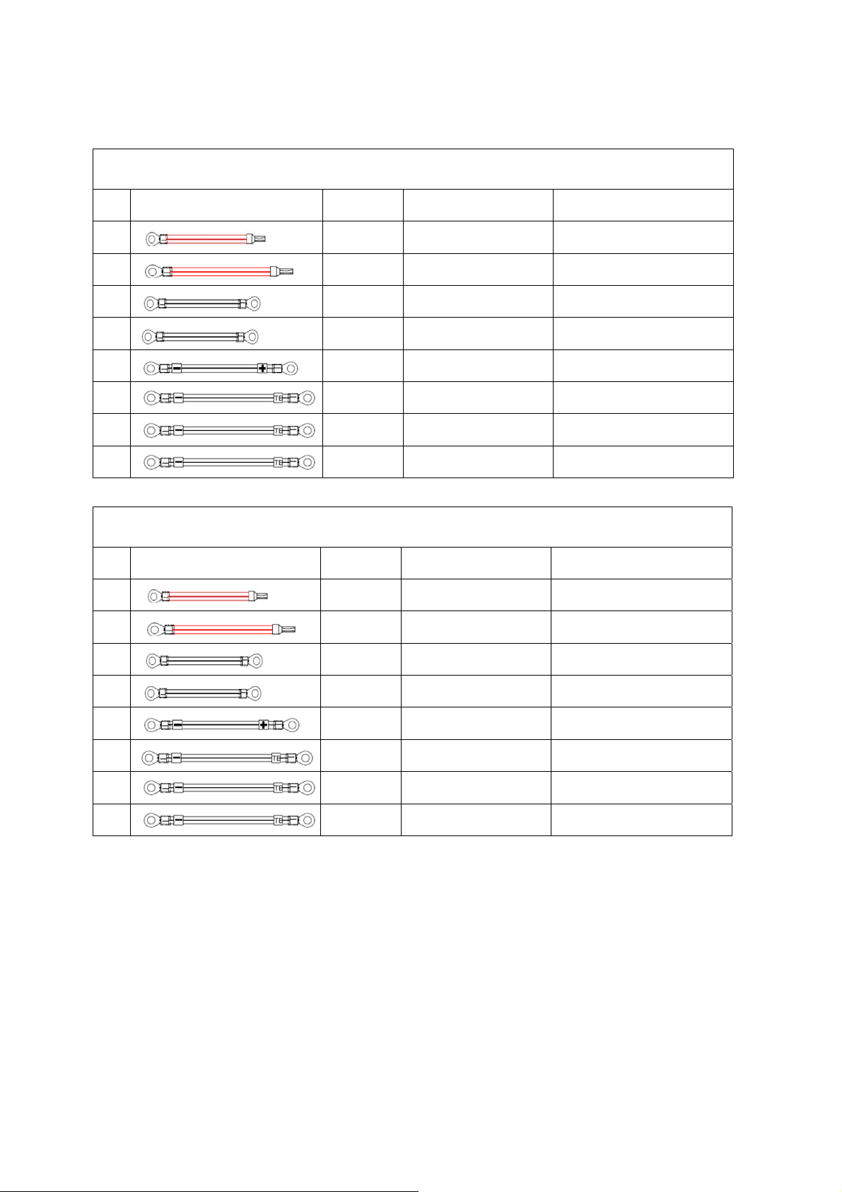
BATTERY CABLE CONNECTION KIT:
SPECIFICATIONS BA TTERY CABLE KIT FOR BOX BATTERY 100Ah
N° Cable Cable Color Cable Specifications Application
1
2
3
4
5
6
7
8
Red L=140mm,AWG#8*2PCS
Red L=480mm,AWG#8*2PCS From battery to breaker
Black L=380mm,AWG#8*2PCS From battery to battery
Black L=250mm,AWG#8*2PCS From battery to battery
Black L=580mm,AWG#8*2PCS From battery to battery
Black L=550mm,AWG#8*2PCS
Red L=2000mm,AWG#8*2PCS From battery box to ATA
Black L=2000mm,AWG#8*2PCS From battery box to ATA
From breaker to battery
terminal block
From battery to battery
terminal block
SPECIFICATIONS BA TTERY CABLE KIT FOR BOX BATTERY 200Ah
N° Cable Cable Color Cable Specifications Application
1
2
3
4
5
6
7
8
Red L=160mm,AWG#8*2PCS
Red L=600mm,AWG#8*2PCS From battery to breaker
Black L=250mm,AWG#8*2PCS From battery to battery
Black L=250mm,AWG#8*2PCS From battery to battery
Black L=700mm,AWG#8*2PCS From battery to battery
Black L=700mm,AWG#8*2PCS
Red L=2000mm,AWG#8*2PCS From battery box to ATA
Black L=2000mm,AWG#8*2PCS From battery box to ATA
From breaker to battery
terminal block
From battery to battery
terminal block
Battery box for ATA Energy Storage System 7 User’s Manual
Page 12
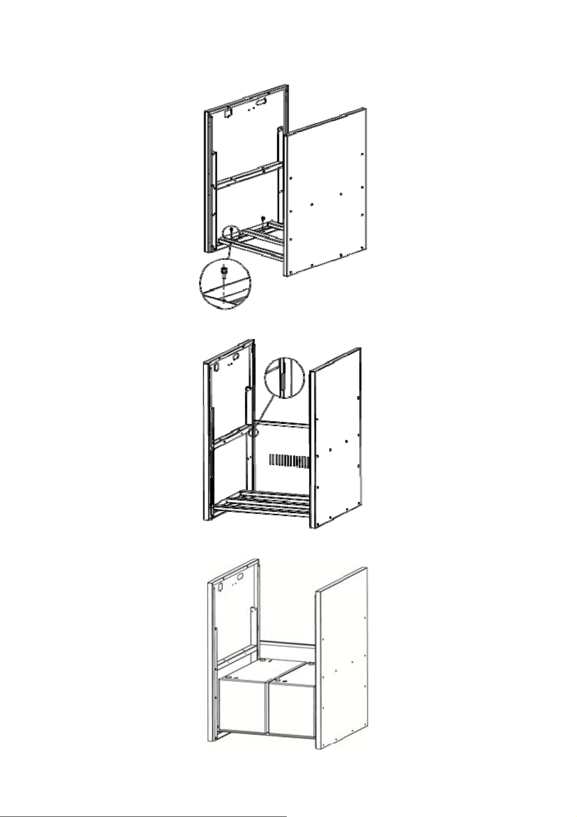
1 Fix bottom bracket between front case and rear case with four M4 screws.
2 Fix one side case in slot between front case and rear case. Refer to below diagram.
3 Put two pieces of batteries on the bottom bracket as shown below.
User’s Manual 8 Battery box for ATA Energy Storage System
Page 13
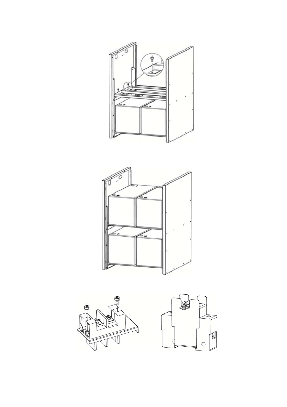
4 Fix one bracket in the middle of battery box with four M4 screws. Refer to below diagram.
5 Put two pieces of battery packs on the middle bracket as shown below.
6 Follow below diagrams to assemble battery connector with connector fixing plate. Insert breaker into U-type fixing plate.
Battery box for ATA Energy Storage System 9 User’s Manual
Page 14
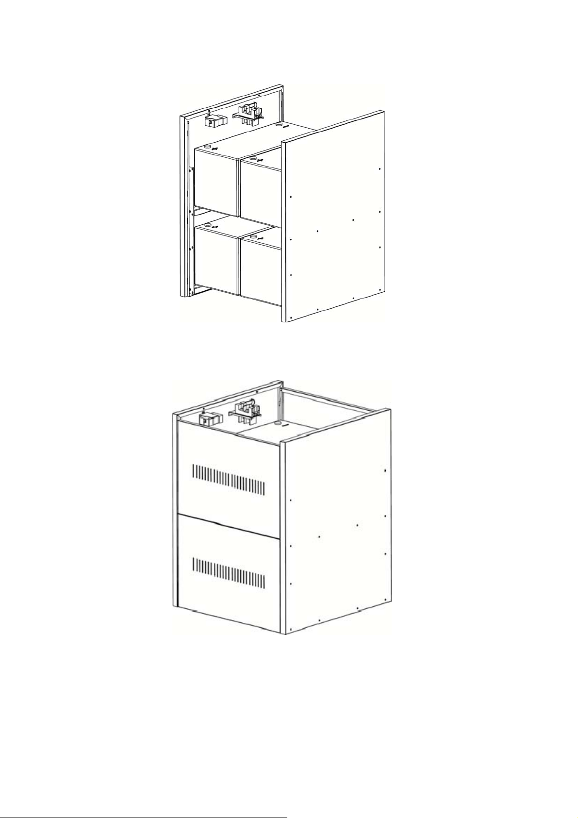
7 Install assembled breaker and battery connector into side case with screws as shown below.
8 Connect the batteries as explained to the chapter 4.1 (for 100Ah batteries) or 4.2 (for 200Ah batteries).
9 Install the remaining 3 pieces of side cases by following same procedure in step 2.
User’s Manual 10 Battery box for ATA Energy Storage System
Page 15
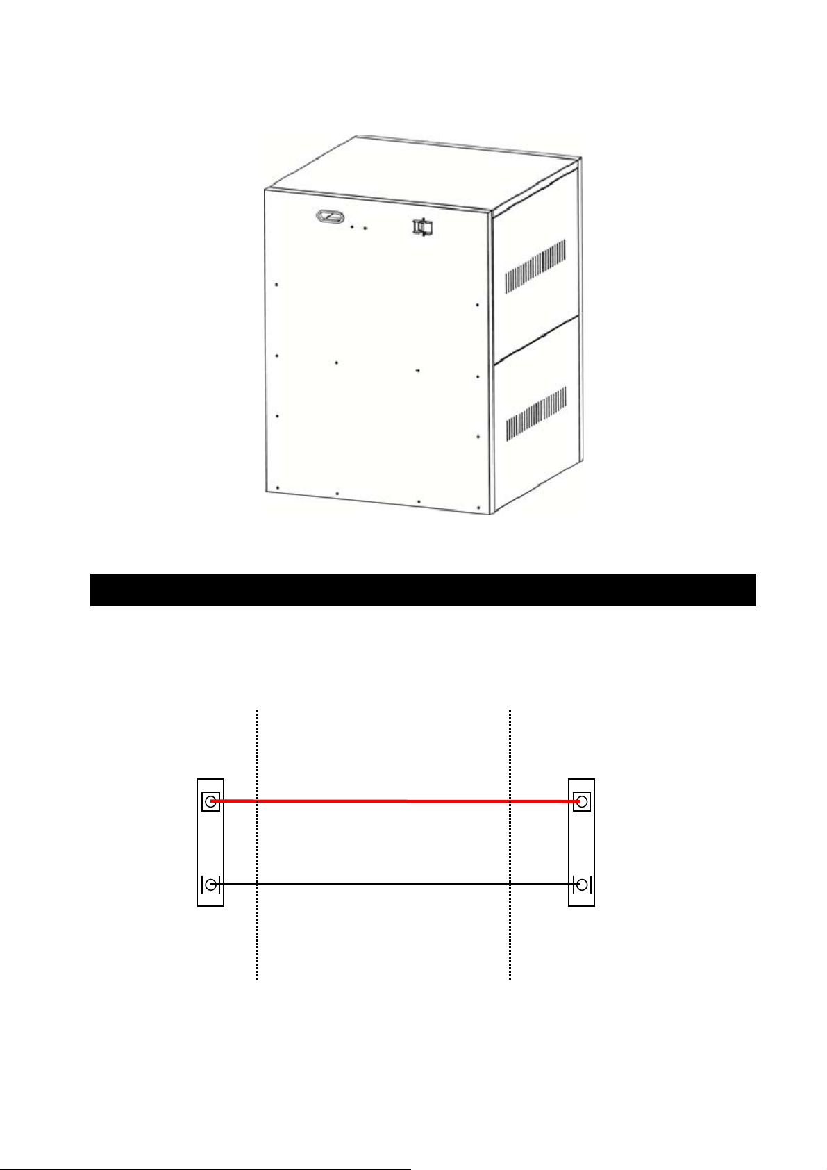
S
R
10 Simply fix top case into slots. Refer to below diagram.
6 Connection with ATA
Through the supplied connecting cables, connect ATA to the ATA battery box (See ATA user’s manual).
To active the system, see the instructions reported in ATA user’s manual.
ATA
+ BATTERIES
+
- BATTERIES
-
ATA BATTERY
CONTACT
BATTERY BOX
+
- BATTE
BOX BATTERY
CONTACT
BATTERIE
IES
Battery box for ATA Energy Storage System 11 User’s Manual
Page 16
Manuale Utente – Italiano
1 Avvisi di Sicurezza
Elevato rischio di shock elettrico: se nel Box Batterie sono state montate le batterie,
all’interno del Box Batterie sono presenti pericolose tensioni che possono provocare
lesioni o morte per shock elettrico.
Interventi tecnici di qualsiasi tipo devono essere compiuti solo da personale tecnico
specializzato ed autorizzato da TECNOWARE. In caso contrario TECNOWARE declina ogni
sua responsabilità.
Pericolo di esplosione o di incendio se si utilizzano batterie di tipo sbagliato o un numero
errato di batterie.
Non avvicinare le batterie al fuoco. Le batterie possono esplodere. Non aprire o
danneggiare le batterie. L’elettrolita contenuto nelle batterie che può fuoriuscire è
nocivo alla pelle e agli occhi.
Il Box Batterie è conforme alle Direttive Europee. Quindi ha il marchio:
1.1 Smaltimento del Prodotto
Il prodotto Box Batterie non può essere smaltito come rifiuto urbano, ma deve esserlo tramite raccolta
separata; qualsiasi violazione è punita con sanzioni pecuniarie ai sensi delle vigenti norme.
Lo smaltimento non corretto del prodotto, o l’uso improprio dello stesso o di sue parti, è dannoso per
l’ambiente e per la salute umana.
Il corretto smaltimento dei prodotti recanti il simbolo del bidone segnato da una croce aiuta ad evitare
possibili conseguenze negative per l’ambiente e la salute umana.
1.2 Batterie al Piombo
Il prodotto Box Batterie può contenere batterie al piombo acido, ermetiche, senza manutenzione.
Tali batterie, se manovrate da personale inesperto, possono essere causa di shock elettrico e di alte
correnti di cortocircuito.
Per questo motivo la rimozione delle batterie può essere compiuto solo da personale tecnico
specializzato ed autorizzato da Tecnoware. In caso contrario Tecnoware declina ogni sua
responsabilità.
Le batterie non possono essere smaltite come rifiuto urbano, ma devono essere smaltite nelle modalità
previste dalla direttiva europea 2006/66/CE; qualsiasi violazione è punita con sanzioni pecuniarie ai
sensi della direttiva stessa.
Manuale Utente 12 Box Batterie per ATA Energy Storage System
Page 17
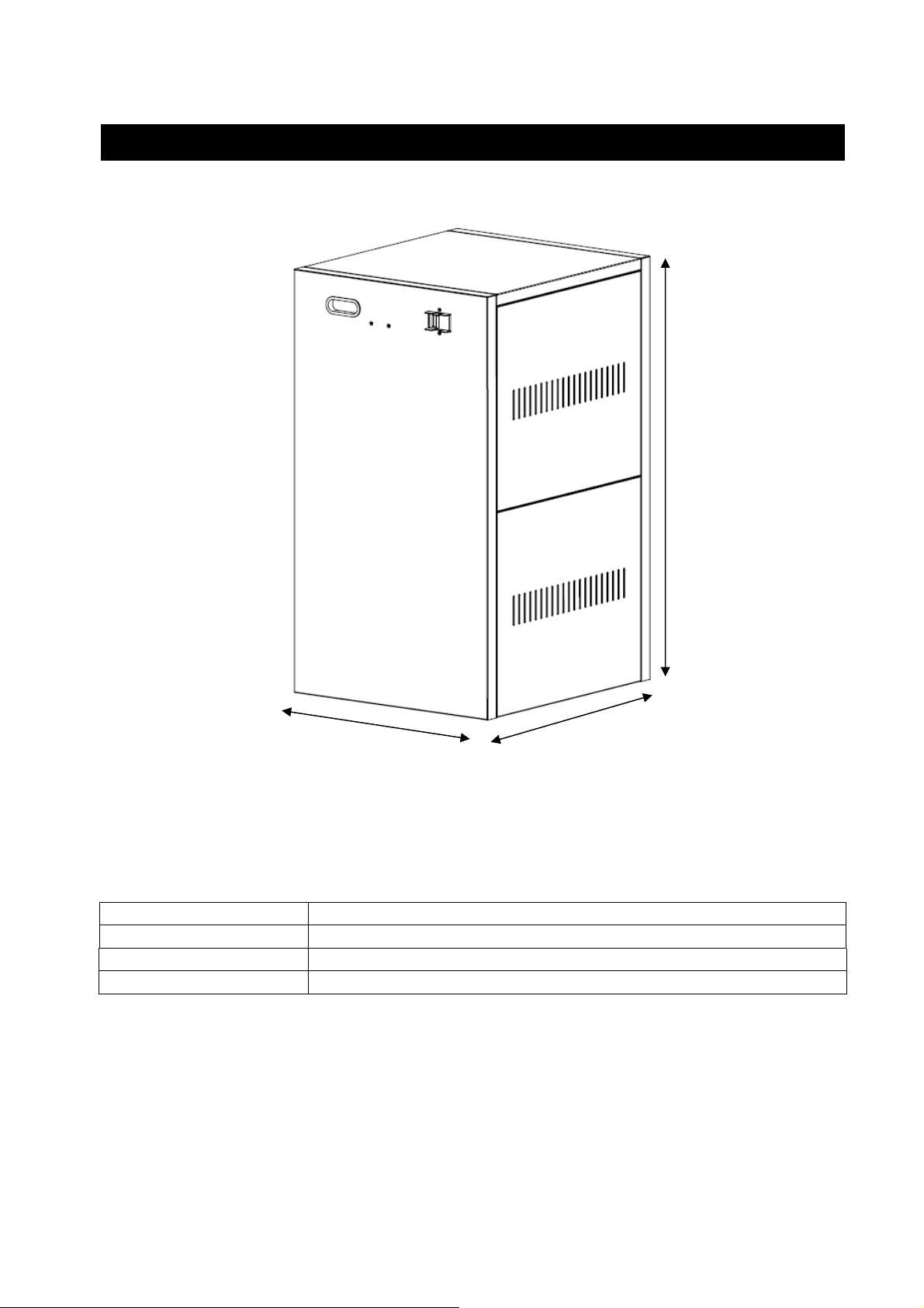
2 Disegno Meccanico Box con Batterie 100Ah
71 cm
Dimensioni (LxHxP) (39.7 x 71 x 44.3) cm
Peso Netto senza Batterie 25 Kg
Numero Batterie 4
Peso Netto con Batterie 100Ah 155 Kg
39.7 cm
44.3 cm
Box Batterie per ATA Energy Storage System 13 Manuale Utente
Page 18
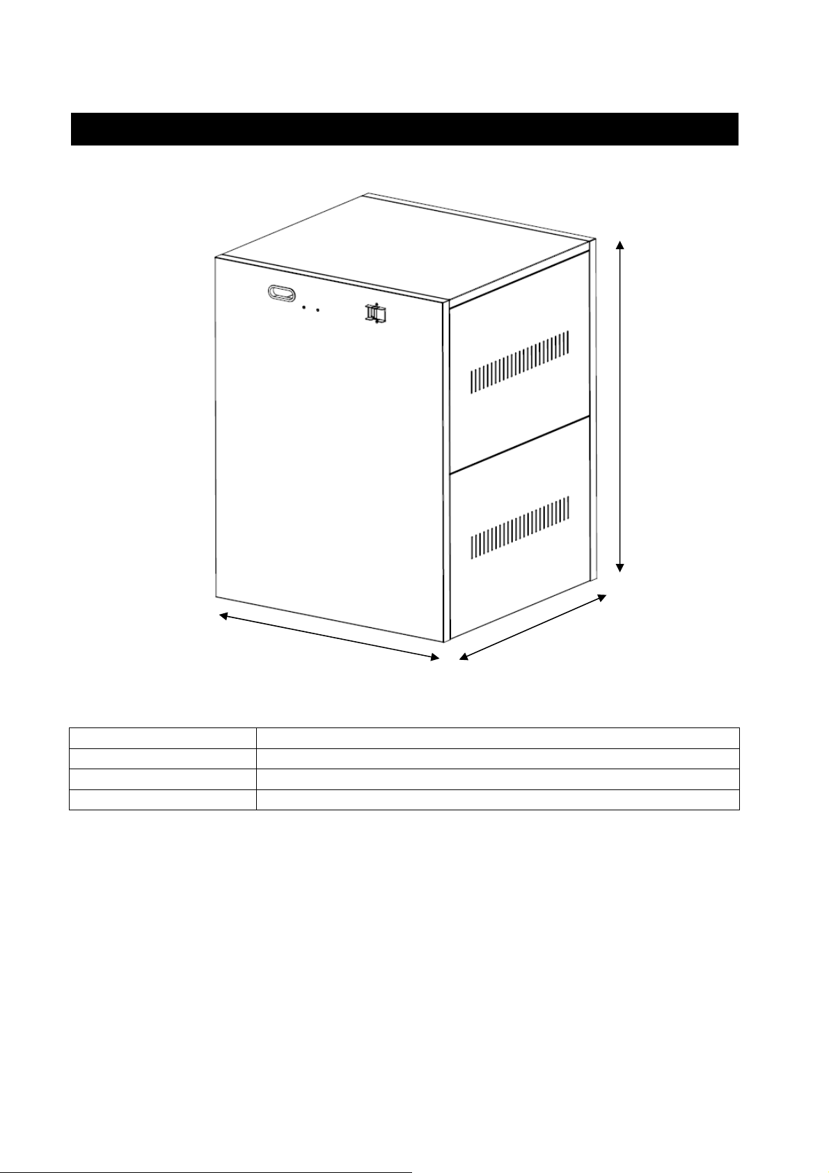
3 Disegno Meccanico Box con Batterie 200Ah
76cm
Dimensioni (LxHxP) (59.5x 76 x 57.5) cm
Peso Netto senza Batterie 36 Kg
Numero Batterie 4
Peso Netto con Batterie 200Ah 300 Kg
59.5 cm
57.5cm
Manuale Utente 14 Box Batterie per ATA Energy Storage System
Page 19
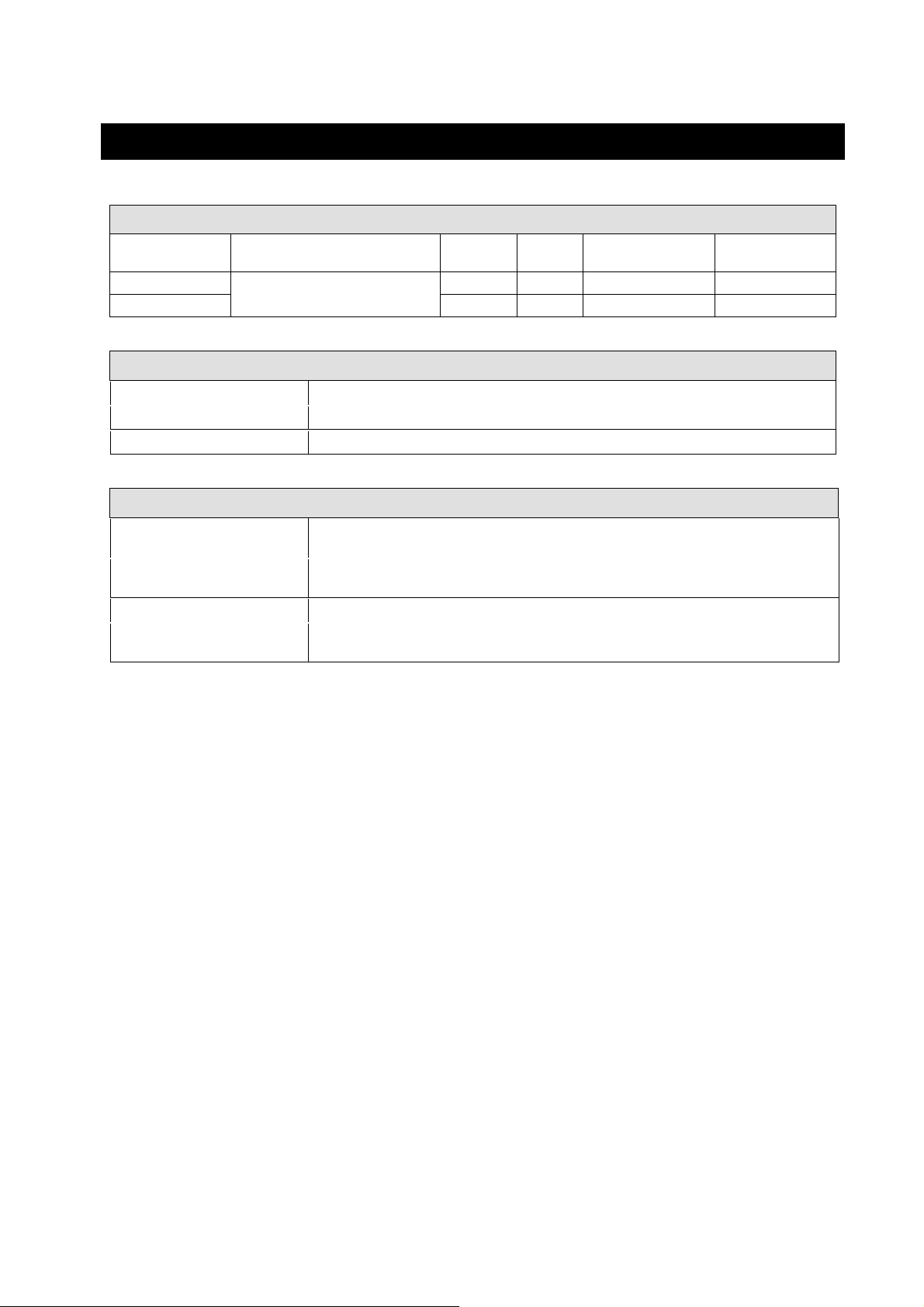
4 FBBATA48V1 e FBBATA48V2
MODELLI DISPONIBILI
Codice Box
Batterie
FBBATA48V1/100
FBBATA48V2/200 4-5 KVA 200Ah 4 AWG (2 x 8 AWG) 125 A
Box Batterie compatibile con ATA
Descrizione
Energy Storage System
Potenza
ATA
4-5 KVA 100Ah 4 AWG (2 x 8 AWG) 125 A
BATTERIE
Tipo Batterie Piombo acido, sigillate, senza manutenzione, 12 Vdc
Numero di Batterie 1 x 4
Tensione Nominale Batterie 48 Vdc
CONDIZIONI AMBIENTALI
Range temperatura
d’immagazzinamento
Range temperatura di
funzionamento
Range umidità relativa 0% - 95% (senza condensazione)
Altitudine massima senza
declassamento
da -25°C a +55°C (è raccomandato da 15°C a 30°C per avere una più lunga vita delle
da 0°C a +40°C (è raccomandato da 20°C a 25°C per avere una più lunga vita delle batterie)
Tipo
Batterie
batterie)
3000 metri
Sezione Cavo Corrente Massima
Box Batterie per ATA Energy Storage System 15 Manuale Utente
Page 20
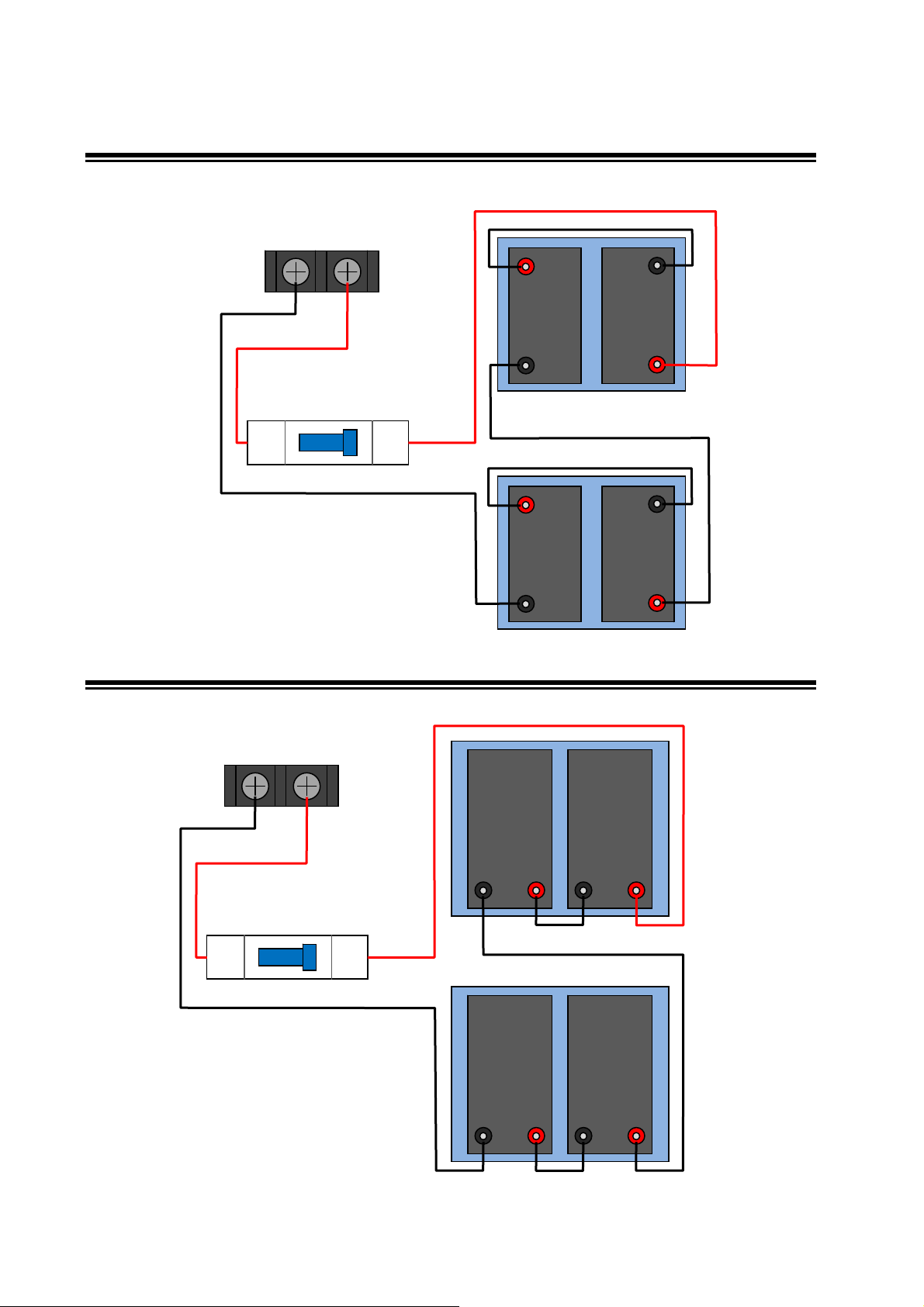
cm 38 cm
4.1 CONNESSIONE BATTERIE 100Ah
TERMINALI PER
COLLEGAMENTO
BATTERIE
14 cm
SECONDO PIANO
SEZIONATORE BATTERIE
OFF ON
55 cm
PRIMO PIANO
4.2 CONNESSIONE BATTERIE 200Ah
+
+
-
SOPRA
38
-
48 cm
-
SOTTO
+
+
-
58 cm
TERMINALI PER
COLLEGAMENTO
BATTERIE
SOPRA
SECONDO PIANO
60 cm
16 cm
-
+
-
+
SEZIONATORE BATTERIE
25 cm
OFF ON
70 cm
PRIMO PIANO
70 cm
-
+
-
+
25 cm
SOTTO
Manuale Utente 16 Box Batterie per ATA Energy Storage System
Page 21
5 Istruzioni Montaggio Box Batterie
CONTENUTO IMBALLO:
Sotto riportato il contenuto dell’imballo:
Numero Descrizione Quantità
1 Coperchio superiore 1
2 Pannelli laterali 4
3 Pannello posteriore 1
4 Pacco batterie * 4
5 Pianetti interni 2
6 Morsettiera batterie 1
7
8
9 Sezionatore Batterie 1
10 Pannello fontale 1
*Le batterie non sono incluse con il box batterie. Nella confezione è compreso il kit per
la connessione delle batterie.
Placca metallica per montaggio
morsettiera
Placca metallica ad U per
montaggio sezionatore batterie
1
1
Box Batterie per ATA Energy Storage System 17 Manuale Utente
Page 22
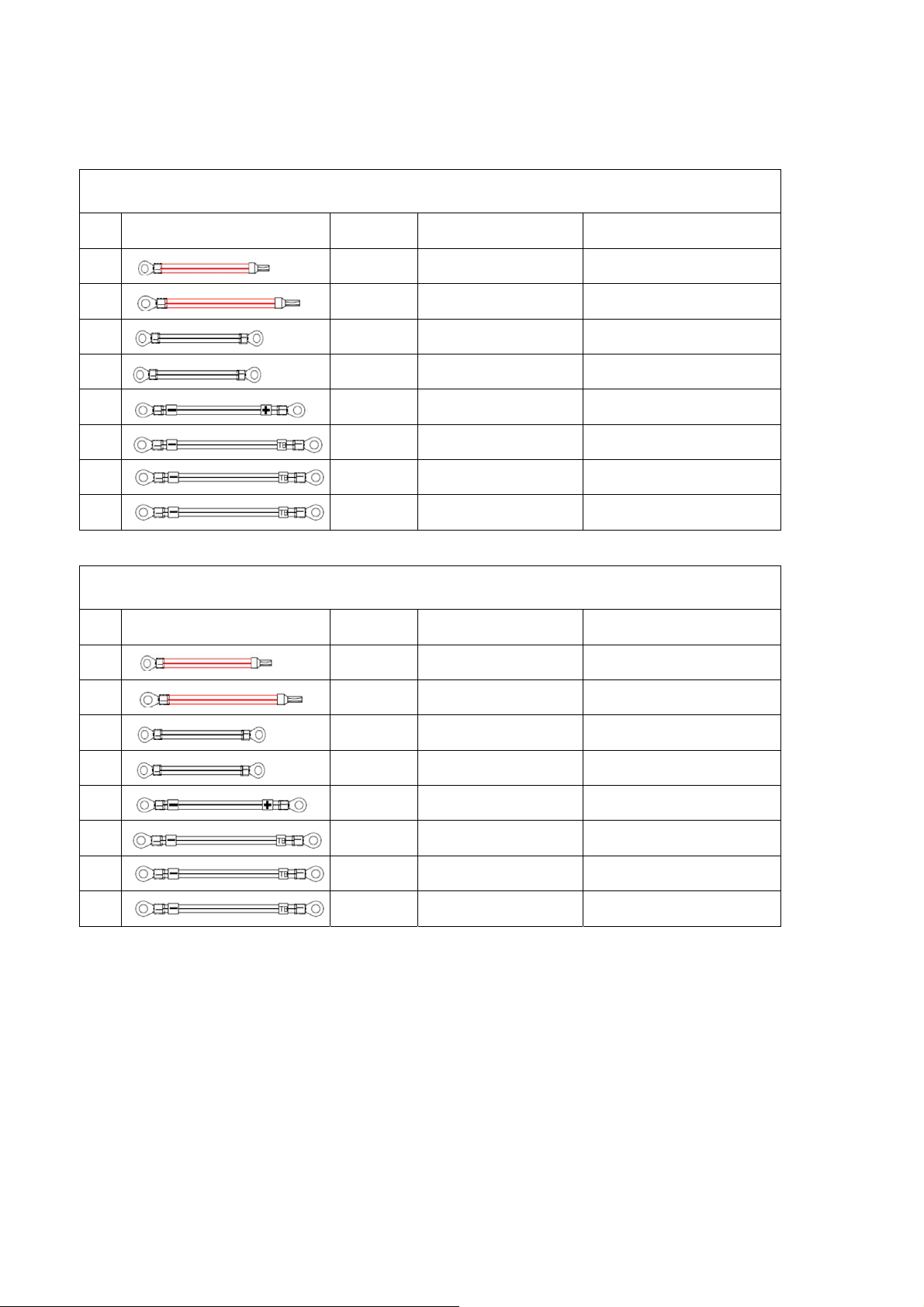
KIT CONNESSIONE BATTERIE:
SPECIFICHE KIT CAVI CONNESSIONI BATTERIE PER BOX BATTERIE 100Ah
N° Cavo Colore Cavo Specifiche Cavo Applicazione
1
2
3
4
5
6
7
8
Rosso L=140mm,AWG#8*2PCS Da sezionatore a morsettiera
Rosso L=480mm,AWG#8*2PCS Da batteria a sezionatore
Nero L=380mm,AWG#8*2PCS Da batteria a batteria
Nero L=250mm,AWG#8*2PCS Da batteria a batteria
Nero L=580mm,AWG#8*2PCS Da batteria a batteria
Nero L=550mm,AWG#8*2PCS Da batteria a morsettiera
Rosso L=2000mm,AWG#8*2PCS Dal box battery ad ATA
Nero L=2000mm,AWG#8*2PCS Dal box battery ad ATA
SPECIFICHE KIT CAVI CONNESSIONI BATTERIE PER BOX BATTERIE 200Ah
N° Cavo Colore Cavo Specifiche Cavo Applicazione
1
2
3
4
5
6
7
8
Rosso L=160mm,AWG#8*2PCS Da sezionatore a morsettiera
Rosso L=600mm,AWG#8*2PCS Da batteria a sezionatore
Nero L=250mm,AWG#8*2PCS Da batteria a batteria
Nero L=250mm,AWG#8*2PCS Da batteria a batteria
Nero L=700mm,AWG#8*2PCS Da batteria a batteria
Nero L=700mm,AWG#8*2PCS Da batteria a morsettiera
Rosso L=2000mm,AWG#8*2PCS Dal box battery ad ATA
Nero L=2000mm,AWG#8*2PCS Dal box battery ad ATA
Manuale Utente 18 Box Batterie per ATA Energy Storage System
Page 23
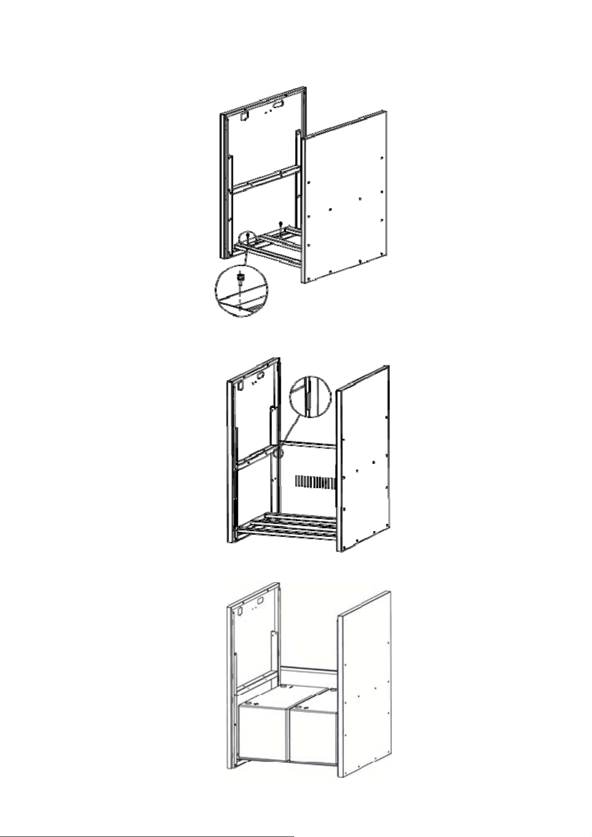
1 Fissare uno dei pianetti interni tra il pannello frontale e quello posteriore utilizzando 4 viti tipo M4.
2 Fissare uno dei pianetti laterali nell’apposito slot tra il pannello frontale e quello posteriore. Fare riferimento all’immagine
sottostante.
3 Posizionare due batterie sul pianetto interno, precedentemente installato, come riportato nell’immagine sottostante.
Box Batterie per ATA Energy Storage System 19 Manuale Utente
Page 24
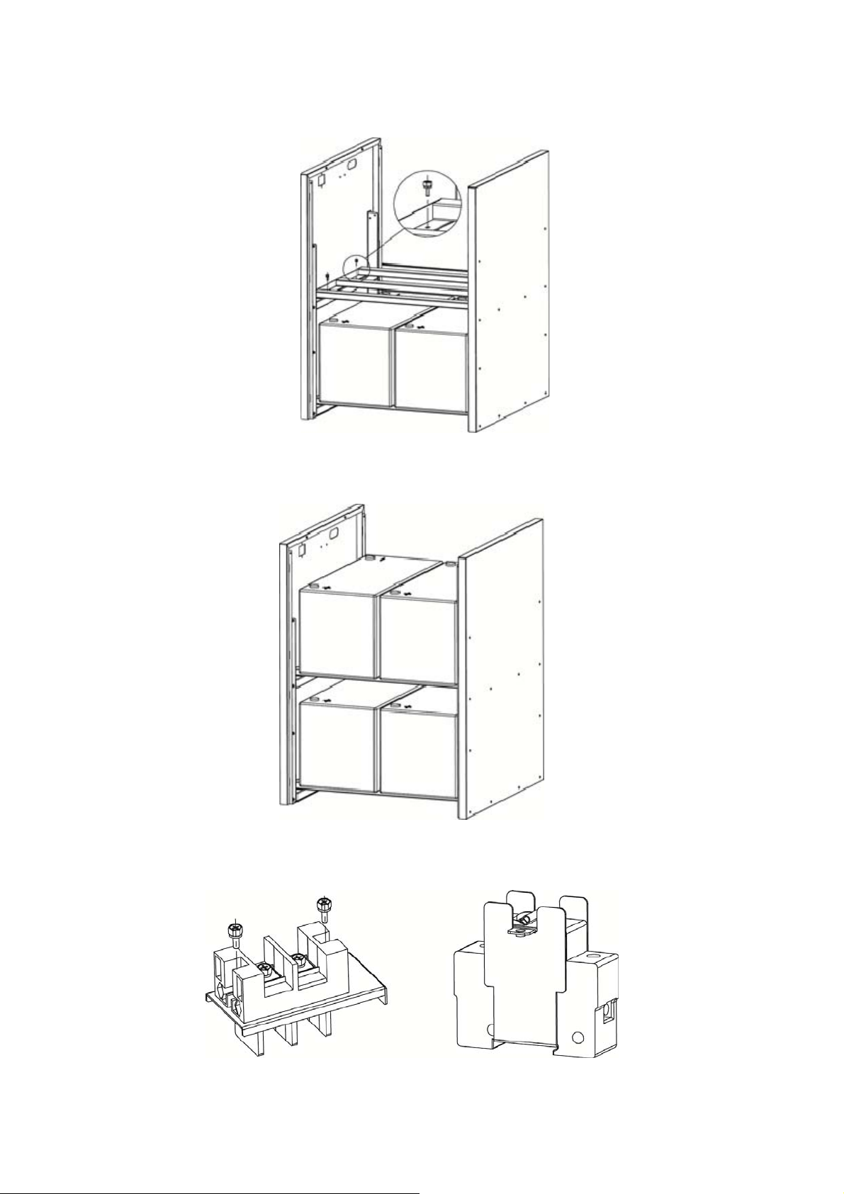
4 Fissare il secondo pianetto interno al centro del box, tra il pannello frontale e quello posteriore, utilizzando 4 viti di tipo
M4. Fare riferimento all’immagine sottostante.
5 Posizionare le altre due batterie sul pianetto centrale come riportato nell’immagine sottostante.
6 Assemblare la morsettiera sul sua placca metallica di montaggio e il sezionatore batterie con placca metallica ad U di
montaggio. Fare riferimento all’immagine sottostante.
Manuale Utente 20 Box Batterie per ATA Energy Storage System
Page 25
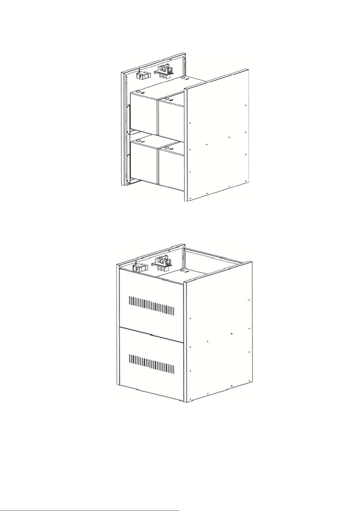
7 Installare la morsettiera e il sezionatore assemblati sul box batterie come riportato nell’immagine sottostante.
8 Connettere le batterie interne come riportato nel capitolo 4.1 (per batterie da 100Ah) o nel capitolo 4.2 (per batterie da
200Ah).
9 Installare i 3 restanti pannelli laterali come precedentemente fatto al punto 2. Fare riferimento all’immagine sottostante.
Box Batterie per ATA Energy Storage System 21 Manuale Utente
Page 26
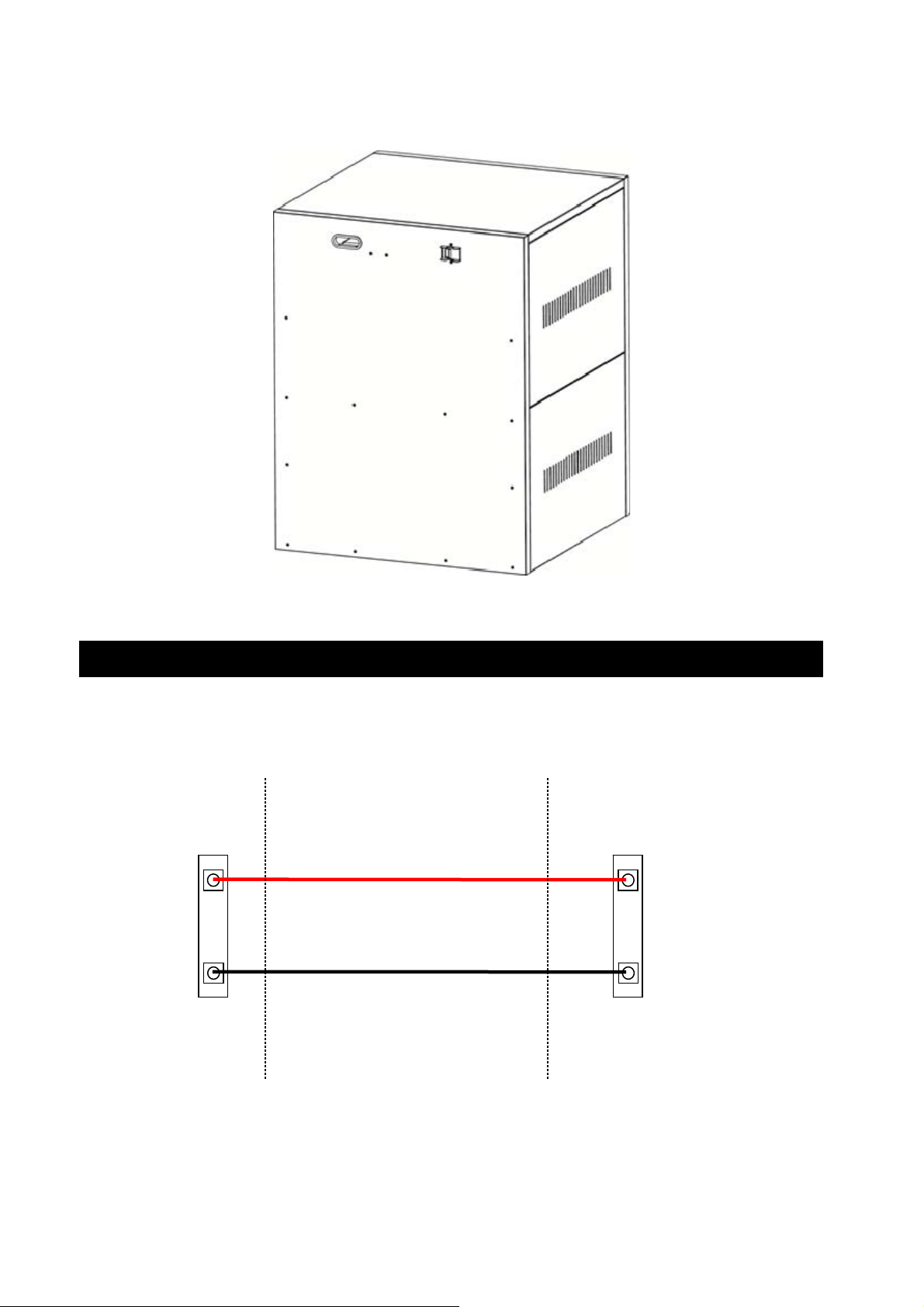
10 Posizione il coperchio superiore sul box batterie come riportato nell’immagine sottostante..
6 Connessione con ATA
Tramite i cavi di collegamento forniti connettere il box batteria all’ATA (vedi manuale ATA).
Per l’attivazione del sistema seguire le istruzioni indicate nel manuale dell’ATA.
ATA
+ BATTERIE
+
- BATTERIE
-
CONTATTI
BATTERIE ATA
BOX BATTERIE
CONTATTI BOX
BATTERIE
+
BATTERIE
-
BATTERIE
Manuale Utente 22 Box Batterie per ATA Energy Storage System
Page 27

Page 28

TECNOWARE s.r.l.
www.tecnoware.com
 Loading...