


EVO TM
Uninterruptible Power Supply
EVO TM 6.0 (6 KVA)
EVO TM 8.0 (8 KVA)
EVO TM 10.0 (10 KVA)
EVO TM 12.0 (12 KVA)
EVO TM 15.0 (15 KVA)
USER’S MANUAL


User’s manual 1 UPS EVO TM
TABLE OF CONTENTS
TABLE OF CONTENTS ......................................................................................................... 1
1.
SAFETY WARNINGS ................................................................................................. 2
2.
INTRODUCTION....................................................................................................... 3
3.
GENERAL CHARACTERISTICS .................................................................................... 4
4.
RECEIPT AND SITE SELECTION.................................................................................. 5
5.
OPERATING MODES ................................................................................................. 5
6.
EXTERNAL DESCRIPTION.......................................................................................... 7
7.
ELECTRICAL INSTALLATION .....................................................................................11
8.
FIRST START UP.....................................................................................................13
9.
FUNCTIONING........................................................................................................14
10. COMPUTER INTERFACE............................................................................................15
11. TECHNICAL CHARACTERISTICS ................................................................................16
12. RECOMMENDATIONS FOR CORRECT USE ...................................................................17
13. TROUBLESHOOTING ...............................................................................................19
14. PICTURES..............................................................................................................21
Copyright 2007 TECNOWARE s.r.l. All rights reserved.
All trademark are property of their respective owners.
TECNOWARE s.r.l.
www.service.tecnoware.com
This manual has been printed and edited by TECNOWARE s.r.l.
December 2007 Edition, version 4.0

UPS EVO TM 2 User’s manual
1. SAFETY WARNINGS
Read this manual carefully and completely before installing and using the
TECNOWARE EVO TM Uninterruptible Power Supply, which, from here after, will also
be referred to as UPS.
The UPS must be used only by properly trained personnel. To ensure correct and safe
operations, it is necessary that operators and maintenance personnel observe the
general safety Standards as well as the specific instructions included in this manual.
Risk of electric shock: do not remove the cover. The UPS contains internal parts
which are at a high voltage and are potentially dangerous, capable of causing injury
or death by electric shock.
There are no internal parts in the UPS which are user serviceable. Any repair or
maintenance work must be performed exclusively by qualified technical personnel
authorized by TECNOWARE. TECNOWARE declines any responsibility if this warning is
disregarded.
The electric installation, has to be done by qualified personnel. Follow all the Safety
Standards (CEI Standards in Italy) for the IN/OUT connections and for the right
section of IN/OUT cables. We recommend to use a dedicated AC input/output power
Line for the UPS.
It is compulsory to ground the UPS according to safety Standards.
Risk of electric shock at the output socket when the UPS is ON.
Risk of electric shock at the output socket while the unit is connected to the AC utility
line.
For respect of the safety norms is necessary the presence of a differential switch
after of the UPS output.
We recommend to use a dedicate AC input/output power Line for the UPS.
Do not obstruct ventilation slots or holes and do not rest any object on top of the
UPS.
Do not insert objects or pour liquids in the ventilation holes.
Install the UPS indoors, in a protected, clean and moisture-free environment.
Do not expose to the direct sun light.
Do not keep liquids, flammable gases or corrosive substances near the UPS.

User’s manual 3 UPS EVO TM
2. INTRODUCTION
UPS EVO TM
The UPS EVO TM (Uninterruptible Power Supplies) are the result of constant technological
research aimed at obtaining the best performance at the lowest cost.
The EVO TM units are advanced ON-LINE UPS built specifically to protect your computer from
any irregularities in the AC line (for example blackouts, brownouts, over voltages, microinterruptions) which often cause damage to hardware and software.
All that is possible because EVO TM is a Double-Conversion ON-LINE UPS.
Under normal AC line condition UPS EVO TM provides an automatic output voltage regulation
from the Rectifier and Inverter blocks and filters out frequently occurring electrical
disturbances (high voltage transients, spikes, interferences, etc.), thus protecting the devices
connected to its outlets. During a power failure, UPS EVO TM continues supplying adequate AC
power (with a true sine wave) to all connected devices through its internal batteries and by its
DC/AC converter (Inverter).
UPS EVO TM protects the devices from accidental overload or Inverter fault by an AUTOMATIC
BYPASS that directly connects the AC input line with its outlets.
The EVO TM models are factory-equipped with a RS-232 interface which may be used for notify
to a computer a power failure or a low battery condition: this allows automatic data backup
during an extended blackout with the most common operating systems (Windows, Novell,
Linux, etc). Thanks to Interface RS232, UPS EVO TM can communicate the several made
measurements (input and output voltage, batteries, absorption, frequency…), and can also be
programmed in order to start-up or shutdown automatically at fixed times.
WARNING
Read this manual carefully before using an UPS EVO TM; it includes important safety
warnings and useful advices for correct use and installation.
EVO TM is constantly being developed and improved: consequently, your unit may differ
somewhat from the description contained in this manual.
This manual includes the follows models of the EVO TM series:
• EVO TM 10.0
• EVO TM 6.0 • EVO TM 12.0
• EVO TM 8.0 • EVO TM 15.0
In this manual, which covers all 5 models, EVO TM will simply be referred to as UPS.

UPS EVO TM 4 User’s manual
3. GENERAL CHARACTERISTICS
UPS EVO TM has all the modern features which guarantee maximum reliability and safety:
Double-Conversion ON-LINE technology
Sinusoidal wave generated by an IGBT INVERTER
Output voltage regulation ±1%
Protection from overload and short circuits
Automatic BYPASS to protect from accidental overload or Inverter fault
Start-up even under MAINS OFF conditions
Automatic protection when battery is low
Automatic restart, following an automatic shut-down due to low battery, once AC
utility power comes back on.
Selectable input frequency (50/60 Hz)
Display LCD for visualization of the input and output voltage measurements,
batteries voltage, percentage of power used, percentage of load, frequency and
operating temperature.
Visual warnings through led, indicating low battery, overload and fault conditions
Dry Contact board (optional)
SNMP Adapter (optional)
EPO (Emergency Power OFF)
Remote ON/OFF
Acoustic signals of various kinds indicating alarm situations
Communication with the computer through RS-232
Available extended autonomy by adding external Battery Boxes
High efficiency
Maximum reliability
Smart design and easy to use.

User’s manual 5 UPS EVO TM
4. RECEIPT AND SITE SELECTION
Carefully remove the UPS from its packaging, and carry out a meticulous inspection. We
recommend keeping the original packaging in case you need to send the UPS for maintenance
purposes. In case of transport damage, notify the carrier and dealer immediately. We
recommend keeping the original packaging in a secure place, in case you need to ship the UPS
for maintenance purposes.
We recommend to pay attention to the below points in order to choose a correct placement for
your UPS:
• The UPS is designed to operate in a protected environment (e.g. offices). We therefore
recommend installing it in a place with very little or no humidity, dust or smoke.
• In all circumstances, see the TECHNICAL CHARACTERISTICS chapter for environmental
specifications and check that the selected area meets these criteria.
• During normal operation UPS EVO TM discharges a minimal amount of heat. So it is
necessary to leave at least 10 cm of unobstructed space all around the UPS in order to
keep it properly ventilated.
• Do not obstruct ventilation holes.
• Do not insert objects or pour liquids in the ventilation holes.
• Do not rest any object on top of the UPS.
• Do not keep liquids, flammable gases or corrosive substances near the unit.
• Install UPS EVO TM on a properly tiled floor. Avoid the installation on a floor that is not
tiled flat.
5. OPERATING MODES
The operation modes are: LINE MODE, BATTERIES mode and BYPASS mode.
For details see figure 1.
LINE MODE
UPS EVO TM typically works in LINE mode, input mains power is available and its amplitude is
within specifications.
After the filter has eliminated any high frequency interferences present on the mains, the input
line Is rectified and conditioned in the RECTIFIER board (AC/DC conversion); the continuous
power now enters into the INVERTER board and is then reconverted in alternated power
(DC/AC conversion), overcoming the AUTOMATIC BYPASS and feeding the load after an extra
filtration. At the same time UPS EVO TM recharges the batteries through the BATTERY
CHARGER block. Please refer to figures 2A/2B, that describes the UPS front panel, the LINE
MODE is identified by:
• Led LINE and UPS are on

UPS EVO TM 6 User’s manual
BATTERY MODE
During operation in the LINE MODE, if the UPS finds the MAINS OFF condition (due to a
blackout or overvoltage/brownout), it then switches into BATTERY mode. In this case, the
batteries supplies the required output power thanks to the DC/AC conversion carried out by
the INVERTER. UPS EVO TM switches back to LINE MODE a few seconds after AC input power
is restored or voltage comes back to internal specifications.
The BATTERY mode is identified by:
• Led LINE off and led UPS on.
• The UPS emits an acoustic signal approximately every 2 seconds, in order to indicate
the BATTERY MODE
The acoustic signal will be automatically de-activated after 90 seconds.
BYPASS MODE
In BYPASS mode, the AC input line is directly connected with the UPS outlets by an
AUTOMATIC BYPASS.
As it is indicated in figure 1, in BYPASS mode the UPS recharge however the batteries.
UPS EVO TM uses the BYPASS mode during the start-up phase; furthermore the UPS
switches automatically to BYPASS mode as a consequence of accidental overload or
Inverter fault thus protecting the supplied devices.
The BYPASS mode is identified by:
• BYPASS Led and LINE led are lit.
When EVO TM functions in BYPASS mode it can be considered as “not active”, since the
INVERTER block is not active.
EVO TM is considered “active” when the INVERTER block is on (LINE mode and BATTERY
mode).
To activate or de-activate UPS EVO TM use the INV ON/OFF button on the front panel.
WARNING
When UPS EVO TM works in BYPASS mode there isn’t output power if the input
power is OFF.

User’s manual 7 UPS EVO TM
6. EXTERNAL DESCRIPTION
FRONT PANEL
On the front panel there is an LCD display, 3 buttons and some led which indicate the various
operating and alarm conditions. Please refer to figure 1, describing the UPS several operation
modes (LINE MODE, BATTERY mode and BYPASS mode) and to the figures 2A/2B we give a
short description of the frontal panel elements.
LCD Display
At the top of the frontal panel is present a two rows LCD display showing the UPS functioning
state and the UPS measurements values. After approximately 2 minutes without pressing any
of the frontal panel buttons the display back-lighting turns off. To relight it press SELECTION
button.
ON Button
By pressing the “ON” button the inverter is activated and will supply the output power within
20 second.
OFF Button
By pressing the “OFF” button for approximately 3 seconds the inverter is deactivated and the
UPS switches in BYPASS mode.
SELECTION Button
Using the button, represented by two vertical arrows, is possible to change the slide visualized
on the LCD display. Every time the button is pressed the slide changes in according to the
sequence described in Table 1 (the display shows the actual screen number visualized by a
fractional number 2/8, 5/8, etc).
Table 1: Indications of LCD display LCD
Display show
Description
TECNOWARE
EVO TM XXX
Welcome message
STATUS
AC:IN BAT:OK
State of the system (*refer following note)
INPUT VOLTAGE
220 V 2/8
INPUT VOLTAGE
OUTPUT VOLTAGE
220 V 3/8
OUTPUT VOLTAGE
INPUT FREQUENCY
50 HZ 4/8
INPUT FREQUENCY
OUTPUT FREQUENCY
50 HZ 5/8
OUTPUT FREQUENCY
BATTERY VOLTAGE
220V 6/8
BATTERY VOLTAGE
CURRENT LOAD
100% 7/8
CURRENT LOAD (%)
TEMPERATURE
33° 8/8
INTERNAL TEMPERATURE

UPS EVO TM 8 User’s manual
*AC and BAT refer respective to the mains voltage and to the battery, in particular:
AC:IN
Normal mains voltage
AC:LOSS
Anomalous mains voltage
BAT:OK
Normal Battery autonomy
BAT:LOW
Low Battery autonomy
Table 2: led present on the frontal panel
Indication on the panel Description
LINE
This led indicates the presence of the input mains voltage is within specifications.
UPS
This led indicates that the inverter is active and supplies the output.
BY-PASS
This led indicates that the UPS is in BYPASS mode and therefore the inverter is
not active.
FAULT
This led indicates the THERMAL PROTECTION FOR OVERLOAD conditions or for
the INVERTER FAULT.
BATTERY LOW
It indicates when the level of the battery is low.
OVERLOAD
Overload indication.
REAR SIDE
To view the rear side of UPS EVO TM (see figure 4):
1. Main switch (ON/OFF): is the general switch of the UPS; in the OFF position it interrupts
the input power line and the battery circuit (see figure 4).
WARNING
UPS EVO TM is completely inactive only if the main switch is in the OFF position (see
figure 4).
If instead the switch is in the ON position, UPS EVO TM is active and voltage is
present in the output.
2. Computer Interface (connector female 9 poles DB9): it is the communication port
RS-232.
3. Metallic panel for access to the input/output terminal board: by removing it and
unscrewing related screws, it is possible to access to the input/output terminal board (see
figure 3).
4. Slot for Dry contact board (optional)/Slot for SNMP adapter (optional).
5. Manual BYPASS switch: to force the UPS into BYPASS mode (see chapter “Running
Operations”).
6. Remote ON/OFF connector.
7. EPO (Emergency Power OFF) connector.
User’s manual 9 UPS EVO TM
EPO (EMERGENCY POWER OFF)
EPO
1
2
REMOTE EPO
SWITCH
The EVO TM models have the EPO, Emergency Power OFF, (
see figure 4),
connector on the rear
side.
This permits to immediately switch the UPS OFF from a distance in case of emergency.
To use an external switch to activate EPO function it is sufficient to connect the switch to the
EPO terminal as described in the above figure.
Warning
If the switch is close the UPS works normally, if on the contrary, the switch becomes
open then the main switch (ON/OFF) releases immediately in OFF position and UPS
turns OFF immediately.
To switch ON the UPS again after an EPO, it is necessary to close the EPO switch and then
manually restart the UPS first moving again the main switch to the ON position end then press
the front panel ON button.
The EPO terminals are isolated and do not need an external feeding voltage.
REMOTE ON/OFF
ON
1
2
Remote ON
Button
OFF
3
4
Remote OFF
Button
5
The EVO TM models have remote ON/OFF terminals connector on the rear side (see figure 4),
this permits to switch the UPS ON and OFF from a distance. Using the ON/OFF external button
(as described in the above picture) the frontal panel button capacity can be used from a
distance.
EVO TM is on; pressing the OFF button connected to terminal 1 and 2 for at least 3 seconds,
EVO TM turns OFF.
EVO TM is off; pressing the ON button connected to terminal 4 and 5 for at least 3 seconds,
EVO TM turns ON.
The remote ON function is disabled when the UPS is off and the AC input line voltage is not
present.

UPS EVO TM 10 User’s manual
DRY CONTACTS BOARD (OPTIONAL)
Com. Fault AC fail Bypass Low Bat Com.
1 2 3 4 5 6 7 8 9 10
The Dry Contacts board has a 10 pin connector on the rear side of the UPS.
1. Common
Pin 1 and Pin 10 are common pins.
2. Fault
Pin 2 is the normal-open output: when UPS works normally, Pin 2 and Pin 1-10 will be open, when UPS is
failed, Pin 2 and Pin 1-10 will be closed.
Pin 3 is normal-closed output: when UPS works normally, Pin 3 and Pin 1-10 will be closed, when is
failed, Pin 3 and Pin 1-10 will be open.
3. AC fail
Pin 4 is the normal-open output: when UPS works normally, Pin 4 and Pin 1-10 will be open, when UPS
works in AC failure mode, Pin 4 and Pin 1-10 will be closed.
Pin 5 is normal-closed output: when UPS works normally, Pin 5 and Pin 1-10 will be closed, when UPS
works in AC failure mode, Pin 5 and Pin 1-10 will be open.
4. Bypass
Pin 6 is normal-closed output: when UPS works normally, Pin 6 and Pin 1-10 will be open, when UPS
works in bypass mode, Pin 6 and Pin 1-10 will be closed.
Pin 7 is normal-open output: when UPS works normally, Pin 7 and Pin 1-10 will be closed, when UPS
works in bypass mode, Pin 7 and Pin 1-10 will be open.
5. Low Bat
Pin 8 is the normal-open output: when UPS works normally, Pin 8 and Pin 1-10 will be open, when UPS
works in Low Battery mode, Pin 8 and Pin 1-10 will be closed.
Pin 9 is normal-closed output: when UPS works normally, Pin 9 and Pin 1-10 will be closed, when UPS
works in Low Battery mode, Pin 9 and Pin 1-10 will be open.
The Dry Contacts board is OPTIONAL

User’s manual 11 UPS EVO TM
7. ELECTRICAL INSTALLATION
WARNING
The electric installation, has to be done by qualified personnel. Follow all the Safety
Standards (CEI Standards in Italy) for the IN/OUT connections and for the right
section of IN/OUT cables. We recommend to use a dedicated AC input/output power
Line for the UPS.
The installation procedure is shown on figures 3 and 4.
EVO TM are made of two separate units: the base unit that contains the electronics and the
BATTERY BOX unit containing the batteries.
WARNING
Before starting the installation procedure, be sure that:
1. Main ON/OFF switch on the rear panel is OFF (see figure 4).
2. AC Input voltage for the UPS is OFF
INSTALLATION
Check the following operations:
1. Remove the metallic panel placed on the rear side. The terminal block is shown in
figure 3. All the cables connected to the terminal block have to reach from the bottom
side using the proper holes on the rear side.
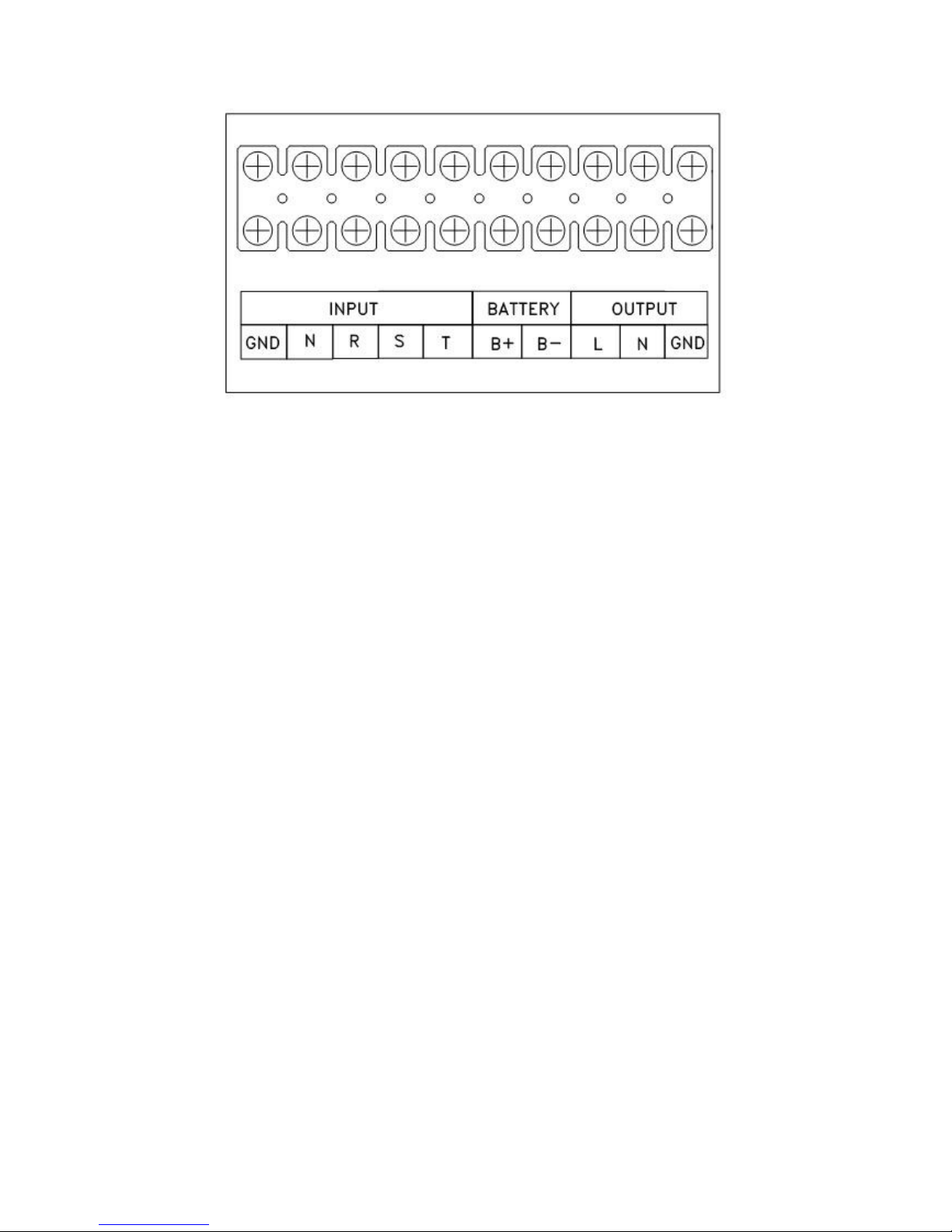
2. Connect the input cables (PHASE R-S-T, LINE and GROUND), paying attention to the right
polarity, in accordance with figure 3:
INPUT R = INPUT R PHASE
INPUT S = INPUT S PHASE
INPUT T = INPUT T PHASE
INPUT N = INPUT LINE
GND = GROUND
3. Connect the three output cables (PHASE, LINE, GROUND):
OUTPUT L = OUTPUT PHASE
OUTPUT N = OUTPUT LINE
GND = GROUND

UPS EVO TM 12 User’s manual
WARNING
All the EVOT TM models need an external BATTERY BOX which must be connected in
accord with the modalities exposed to point 4, because this models don’t have
internal battery.
WARNING
The instructions below describe the operations to connect in right way the UPS to a
BATTERY BOX supplied by Tecnoware.
We suggest to use only BATTERY BOX supplied by TECNOWARE. TECNOWARE declines
any responsibilities if this rule is not followed.
Before starting whichever operation be sure that the switch of BATTERY BOX is in
position OFF: in order to approach to the switch place is necessary remove the
metallic panel on the back of BATTERY BOX.
4. Proceed with the connection of BATTERY BOX (if present) through the following operations:
- Connect, the red cable in equipment, terminal 4 (called BATTERY B+) of the UPS
terminal blocks to the terminal (+) on the BATTERY BOX.
- Connect, the black cable in equipment, terminal 3 (called BATTERY B-) of the UPS
terminal blocks to the terminal (-) on the BATTERY BOX.
- Connect, the green and yellow cable in equipment, terminal (GND) of the UPS
terminal blocks to the terminal (GND) on the BATTERY BOX.
5. Reassemble the metallic panel that gives access to the terminal blocks.
6. Place the switch of BATTERY BOX in the ON position.
7. Reassemble the metallic panel of the BOX BATTERY.
8. Restore the input mains voltage to the UPS.
WARNING
The terminals 4 (BATTERY+) and 3 (BATTERY-) have to be used exclusively for the
external box battery connection. Otherwise they MUST NOT BE CONNECTED.
WARNING
It is compulsory to ground the UPS according to Safety Standards.
The UPS is internally connected to the ground terminal (GND) of the IN/OUT terminal
blocks (see figure 3) in order to guarantee safety to the user. For this safety rule to
be effective it is necessary to make sure that the local electrical installation is
supplied with ground (in compliance with the norms in force) and that a valid
connection is guaranteed between the ground of the UPS and the ground of the local
electrical installation.
Any interruption of the ground conductor is absolutely prohibited.
Risk of electric shock at the output socket if the UPS is ON, even when the UPS is not
connected to AC utility line.
Risk of electric shock at the output socket while the unit is connected to the AC utility
line.

User’s manual 13 UPS EVO TM
WARNING
We recommend to use a dedicate AC input/output power Line for the UPS.
Risk of electric shock: do not remove the cover. The UPS contains internal parts
which are at a high voltage and are potentially dangerous, capable of causing injury
or death by electric shock.
There are no internal parts in the UPS which are user serviceable. Any repair or
maintenance work must be performed exclusively by qualified technical personnel
authorized by TECNOWARE. TECNOWARE declines any responsibility if this warning is
disregarded.
Disregard for these warnings may lead to a risk of electric shock to operators
8. FIRST START UP
Turning the UPS on is very easy. Nevertheless we recommend that, on first start up, the
following procedure is observed for greater safety.
1. Check if the main on the rear side is in the OFF position.
2. Check that no load is connected to the UPS output.
3. Check that the AC input voltage is within input specifications.
4. Turn ON the main switch placed on the rear; LINE led, BYPASS led and fans turn ON; UPS
EVO TM works in BYPASS mode.
5. Press the ON button on frontal panel: the led LINE and BYPASS still remains on, and
display LCD will light; UPS EVO TM is functioning in BYPASS mode.
6. After approximately 20 sec. the inverter starts: led LINE still remains on, but the BYPASS
led turns off, and will light UPS led; LCD display shows welcome message and UPS EVO TM is
functioning in LINE mode.
7. Simulate a black-out removing the AC utility line. UPS EVO TM starts working in BATTERY
mode and LINE led turns OFF. Moreover UPS emits a brief acoustic signal every 2 seconds, for
approximately 90 sec and then it turns off automatically. When battery level is ending the
acoustic signal will be emitted every 1 second.
8. Restore AC utility line. LINE led turns ON, and after a few seconds UPS EVO TM turns back
in LINE mode.
9. UPS EVO TM has passed first start up check: now connect the loads to be supplied to the
UPS output and turn on them, checking UPS doesn’t report OVERLOAD informations
(OVERLOAD led turned off). By LCD display check the connected load percentage is less than
100% otherwise is necessary to remove part of the loads at the output line.
Before using UPS EVO TM leave it in LINE mode for at least 10 hours in order to charge battery
completely (UPS EVO TM charges battery also in BYPASS mode). The batteries arrive at 90%
of their capacity after about 10 hours of recharge.

UPS EVO TM 14 User’s manual
9. FUNCTIONING
TURNING ON AND OFF
UPS EVO TM is equipped with a main switch placed on the rear (see figure 4). If this switch
is in OFF position than UPS is completely OFF; else UPS is ON in one of the three functioning
modes (LINE mode, BATTERY mode, BYPASS mode).
If UPS is used daily is recommended to leave the main switch always ON and turn ON/OFF the
UPS by the ON and OFF buttons on the frontal panel to activate/de-activate the INVERTER.
If UPS EVO TM has to be turn OFF for several days is recommended to turn OFF the main
switch.
Let’s see carefully the consequences of the pressure of buttons ON and OFF.
The UPS is in BYPASS MODE (INVERTER is OFF); if the ON button is pressed, after few seconds
the INVERTER starts and after 20 seconds UPS switches in LINE mode.
If the ON button is pressed when AC utility line is not present, UPS EVO TM switches on even,
and works in BATTERY mode after about 20 seconds.
If UPS is ON, press OFF button continuously for approximately 3 seconds to deactivate
INVERTER: if AC utility line is present, then the UPS switches from LINE mode to BYPASS
mode, but if the UPS is functioning in BATTERY mode, then the INVERTER switches off and
consequently there will be no output power.
WARNING
As showed before, in BYPASS mode, the INVERTER is de-activated and UPS EVO TM
doesn’t work as a UPS, but only as a bypass between input and output of the mains.
In BYPASS mode, the UPS supplies the load only if AC utility line is restored. The load
in BYPASS mode isn’t protected in case of black-out.
LOW BATTERY AND AUTOMATIC RESTART
UPS EVO TM reaches LOW BATTERY condition (BATTERY LOW) whenever, during functioning
in BATTERY mode, the battery reaches a charge level allowing connected devices to operate for
approximately 1,5 more minutes.
UPS EVO TM warns operators of LOW BATTERY lighting the BATTERY LOW led, by emitting an
acoustic signal every second, and on LCD display is visualized the message:
“AC: LOSS BAT: LOW ”.
If AC utility power does not come back on within a minute, the UPS shuts down
automatically thus preventing the battery from discharging excessively; EVO TM stops
supplying output power, deactivates control panel indication and goes to a waiting state. Once
AC utility power comes back on, it restarts automatically like is pressed ON button in frontal
panel and after 20 seconds backs to work in LINE mode.
After a complete discharge, the UPS needs 10 hours to recharge completely the batteries. UPS
recharges batteries automatically if it works in LINE mode or in BYPASS mode.

User’s manual 15 UPS EVO TM
LOAD TESTING
UPS EVO TM indicates the output power percentage (respect to the nominal value) by the LCD
display, visualizing it on the second row of the display.
UPS EVO TM has the capability to accept an overload less than 110% for an indefinite time.
An overload between 110% and 150% (indicate by an intermittent acoustic alarm and
OVERLOAD led flashing) respect to the nominal value, is accepted for about 20 seconds and
after UPS switches automatically to the BYPASS mode.
An overload higher than 150% is accepted for 10 cycles (about 200 ms), but after UPS EVO TM
switches automatically to the BYPASS mode.
Once the requested power is back within range, UPS EVO TM switches automatically to the LINE
mode.
WARNING
OVERLOAD led indicates overload condition. Make sure that the UPS never indicates
OVERLOAD.
Do not connect a load greater than rated value to the UPS (see POWER specifications in
the chapter TECHNICAL CHARACTERISTICS), as this may damage the unit. In this case
the warranty is void.
10. COMPUTER INTERFACE
UPS EVO TM is factory-equipped with a RS-232 Interface to be used to communicate with a
Personal Computer.
On the rear side of the UPS there is a 9-pin female connector (DB9).
On the DB9 connector there are the following signals:
•
RX
(pin 2)
•
TX
(pin 3)
•
GND
(pin 5)
To control with a Computer the UPS status (LINE or BATTERY mode functioning, LOW BATTERY
condition, UPS safety shot up conditions), check the measurements (mains voltage, output,
battery voltage, frequency, etc.) and program automatic start up and shout up times, is
available (optional) an interface kit (software and cable connection compatible with the most
used Operative System).
The signals of the RS232 Interface are OPTOCOUPLED.

UPS EVO TM 16 User’s manual
11. TECHNICAL CHARACTERISTICS
UPS EVO TM MODEL 6.0 TM
8.0 TM 10.0 TM
12.0 TM
15.0 TM
POWER
6000 VA
4800 W
8000 VA
6400 W
10000 VA
8000 W
12000 VA
9600 W
15000 VA
12000 W
TECNOLOGY
ON-LINE Double Conversion with transformer
NOMINAL INPUT VOLTAGE
Triphase 380 V
INPUT VOLTAGE RANGE
+
20% / -25%
INPUT / OUTPUT FREQUENCY
50 / 60 Hz (selectable)
INPUT FREQUENCY RANGE
±5%
NOMINAL OUTPUT VOLTAGE Monophase 220 / 230 V
OUPUT VOLTAGE REGULATION ±1%
OUTPUT INVERTER WAVEFORM TRUE SINE WAVE
OUTPUT TOTAL HARMONIC DISTORSION (THD)
< 3%
OVERLOAD ACCEPTED
< 150% for 30 sec; > 150% for 10 cicli
TRANSFER TIME (typical)
0 ms (ON-LINE)
AUTOMATIC AND MANUAL BYPASS
Uninterrupted transfer of 100% load from UPS to Bypass and vice versa
CERTIFICATIONS
CE (reference: CEI EN 62040-1-1; CEI EN 62040-2 / EN 50091-2)
BACK UP TIME (typical) 10 10 8 6 10
NOMINAL BATTERY VOLTAGE
192 Vcc
SEALED, MAINTENANCE FREE, LEAD ACID
BATTERY
16 units
12V 7,2Ah
16 units
12V 9Ah
16 units
12V 9Ah
16 units
12V 9Ah
32 units
12V 9Ah
SET POSITIONING BATTERIES Box battery
RECHARGE TIME (typical) 8 ore
AUDIBLE NOISE (at 1 meter) < 50 dBA
COOLING
Forced by cooling fan
NET WEIGHT (Kg)
118 (UPS)
66 (Box Bat.)
135(UPS)
74 (Box Bat.)
155 (UPS)
74 (Box Bat.)
195 (UPS)
74 (Box Bat.)
262 (UPS)
119 (Box Bat.)
DIMENSION (W x H x D) cm
31 x 87 x 59 (UPS)
27 x 73 x 63 (Box Batterie)
73 x 118 x 46
(UPS)
27 x 73 x 63
(Box Batterie)
OPERATIVE ENVIRONMENTAL
SPECIFICATIONS
Temperature: 0-40 °C
Humidity: 0-95% (without condensation) Maximum altitude: max 3.000mt
EXTENDED AUTONOMY
Available, by external box battery (optional)
COMPUTER INTERFACE
1 port RS232
SOFTWARE Included software UPSilon 2000 compatible with: Windows, Linux, Novell
EPO (Emergency Power OFF)
Included
REMOTE ON/OFF Included
DRY CONTACTS BOARD Optional
SNMP ADAPTER Optional
IN/OUT Terminal Blocks On the rear, in the bottom part
EQUIPMENT
Software UPSilon 2000 and serial cable
WARRANTY
2 years
TECHNICAL DATA MAY CHANGE WITHOUT PRIOR NOTICE

User’s manual 17 UPS EVO TM
12. RECOMMENDATIONS FOR CORRECT USE
UPS CLEANING
WARNING
Before any cleaning operation, make sure that the main switch (see figure 4) of the
UPS is OFF and that mains input power has been removed.
Use only a cloth dampened with water to clean the unit.
If UPS works in an environmental unusually dusty or dirty, remove the dirty from the
ventilation holes.
Before to restart UPS EVO TM be sure it is completely dry. If any liquid gets inside the UPS, do
not start the unit and contact authorized technical personnel immediately.
INPUT/OUTPUT CONNECTIONS
WARNING
Before any checking operation, make sure the main switch (see figure 4) of the UPS
is OFF and that mains input power has been removed.
We recommend checking periodically the input power cord, the output connections and the
IN/OUT Terminal Board.
LONG NOT WORKING PERIODS
If EVO TM is not going to be used for a long period of time, we recommend to perform the
following operations:
• make sure that the battery is left fully charged
• position the main switch in OFF position to full turn off the UPS.
If the UPS has not been used for more than three month, go through the procedure described
in the chapter FIRST START UP before using it again.
Please keep in mind that battery must be recharged at least once a month. Take in mind that
the battery is recharged automatically (if the UPS is on and working in LINE or in BYPASS
mode) for approximately 10 hours with AC utility line present.
BATTERIES EFFICIENCY
We recommend checking batteries every six month. To check the batteries it is sufficient to
switch the UPS in BATTERY mode for some minutes.

UPS EVO TM 18 User’s manual
PROTECTION OF POWERED DEVICES
The UPS assure continuos adjusted and jammed alimentation only if it is NOT functioning in
BYPASS mode. In this mode the INVERTER is off and at the output there is only the voltage
that is present at the input by the AUTOMATIC BYPASS
To light powered devices by the UPS make following operations:
• If UPS EVO TM is in BYPASS mode press ON button on frontal panel and wait the
passage in LINE mode
• Turn on all the devices using the relative switches.
To turn off devices make following operations:
• Turn off all devices using the relative switches.
• Press OFF button on frontal panel so to generate switching in BYPASS mode
We recommend to oversize the UPS about 20% referring to nominal power requested
by the devices to supply.
OPERATOR SAFETY
Whenever UPS EVO TM is not responding anymore to original characteristics, the UPS must
become not operative and every usage not authorised must be avoided. After will be necessary
to refer to qualified technical personnel.
Original safety characteristics might not be if, per example, UPS EVO TM presents visible
damages or irregular functioning.

User’s manual 19 UPS EVO TM
13. TROUBLESHOOTING
Following are described some functioning anomalies and relating solutions:
UPS doesn’t lights on without giving any information
• Check if main switch on the rear is in ON position.
UPS continues to function in BATTERY mode also if AC input line is
present at the input
• Make sure that is present AC input line at the input of the UPS and that AC input line
voltage amplitude is inside specified ranges.
• Before making following operations turn off the UPS, positioning main switch
on the rear side on OFF, and removing AC input line at UPS input.
• Check all input line cables.
• Check connections to IN/OUT terminal blocks.
OVERLOAD indication on the UPS
• Check UPS powered devices and if UPS is really overloaded.
• Report power request in specified range disconnecting devices that generates overload.
UPS POWERED DEVICES DOESN’T LIGHTS ON
• Before making following operations turn off the UPS, positioning main switch
on the rear side on OFF, and removing mains voltage at UPS in.
• Check connections with in/out terminal blocks.
• Check for every single connection cable state.
Overload thermic protection or inverter fault
The anomaly condition is highlighted by:
• FAULT led lighting on and continuos acoustic alarm signal
Make the following operations:
• Deactivate the INVERTER the OFF button.
• Disconnect all loads at the UPS output.
• Reactivate the INVERTER pressing the ON button.
• Check that UPS EVO TM is functioning regularly in LINE mode and the FAULT led off
(alarm disappeared).
• In event of alarm disappeared reconnect by degrees the output load, locating and
removing the ones generated alarm condition.
The UPS autonomy is less then specified
• Recharge batteries for at leas 10 hours and then check again their autonomy.

UPS EVO TM 20 User’s manual
Risk of electric shock: do not remove the cover. The UPS contains internal parts
which are at a high voltage and are potentially dangerous, capable of causing injury
or death by electric shock.
There are no internal parts in the UPS which are user serviceable. Any repair or
maintenance work must be performed exclusively by qualified technical personnel
authorized by TECNOWARE.
TECNOWARE declines any responsibility if this warning is disregarded.
If the described anomalies should continue despite the advised troubleshooting, or
should they manifest in any other form, please contact
TECNOWARE SUPPORT
www.service.tecnoware.com

User’s manual 21 UPS EVO TM
14. PICTURES
Figure 1 – Functioning mode

UPS EVO TM 22 User’s manual
ON
OFF
LINE
UPS
BY-PASS
LOAD
-
ON LINE SYSTEM
UNINTERRUPTIBLE POWER SUPPLY
+
Figure 2A – Frontal Panel for
EVO TM 6.0, EVO TM 8.0, EVO TM 10.0, EVO TM 12.0
1. ON button
2. OFF button
3. SELECTION button
4. BATTERY LOW led (yellow)
5. OVERLOAD led (red)
6. FAULT led (red)
7. LINE led (blue)
8. UPS led (blue)
9. BY-PASS led (blue)
10. LCD Display

User’s manual 23 UPS EVO TM
Figure 2B – Frontal Panel for EVO TM 15.0
BUTTON LED
LINE
OFF Button
UPS
BYPASS
ON Button
FAULT
BATTERY LOW
SELECTION Button
OVERLOAD
UPS EVO TM 24 User’s manual
Figure 3 – IN/OUT Terminal Blocks

User’s manual 25 UPS EVO TM
RS232
RS232
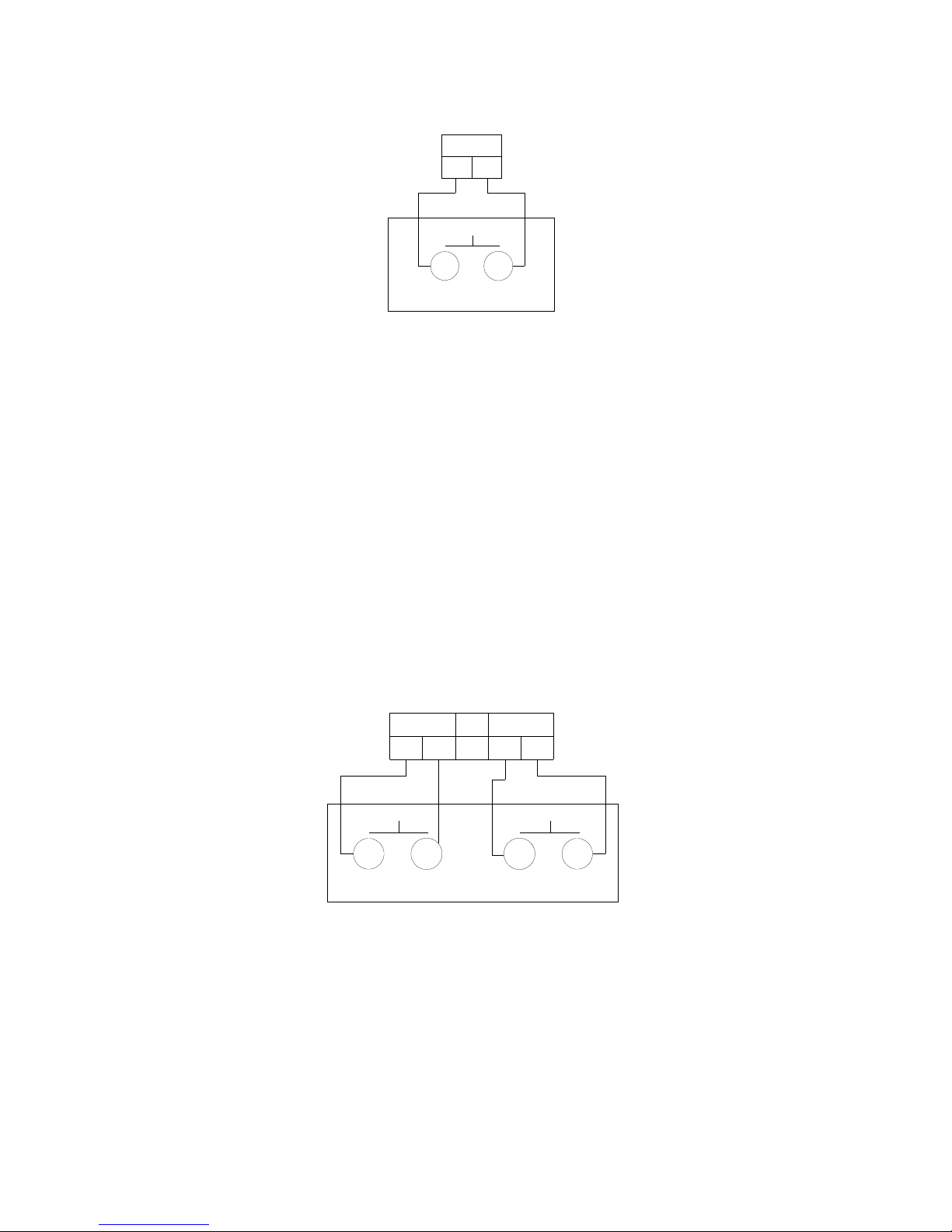
Figure 4 - UPS EVO TM rear view
On the left: EVO TM 6.0, in the middle: EVO TM 8.0, EVO TM 10.0, EVO TM 12.0; on the right: EVO TM 15.0
1. Main Switch
WARNING Only EVO TM 8.0 -15.0
Mains Switch (1) is made by 2 switches:
(1A): AC input switch (breaker)
(1B): BATTERY switch (breaker)
Main Switch in ON position means: both switches (1A) AC input breaker (1B) and BATTERY
breaker are in ON position.
Main Switch in OFF position means: both switches in OFF position.
2. RS232 communication port
3. Metallic panel for access to IN/OUT terminal blocks
4. Manual BYPASS Switch
5. Slot for Dry Contact Board / Slot for SNMP adapter
6. Remote ON OFF connector
7. EPO (EMERGENCY POWER OFF) connector

UPS EVO TM 26 User’s manual
WARRANTY RULES– valid in all UE countries
TECNOWARE S.r.l. guarantees the product for a period of 24 months from the original date of
purchase.
The date of purchase is proved with the receipt of account released by the authorised reseller,
which clearly indicates the date in which the product was sold and the product identification code
(model and serial number). Upon request of Technical assistance, a copy of your receipt must be
surrendered.
This guarantee implies free reparation or free substitution of any products parts or components
which result faulty due to defective manufacture.
In the event of irreparable fault, or should the same malfunction repeat itself, TECNOWARE S.r.l
will provide the final decision on the product substitution.
Any parts damaged due to the negligence or carelessness in using the product (such as failing to
follow the correct operating instructions indicated in the user manual), violations, incorrect
installation or maintenance operated by non authorized personnel, transportation damages,
natural calamities, accidental causes, phenomenon not subordinated to the normal product
functioning, non qualification of environment in which the product operates, and in any case: any
circumstances in which one cannot date back to the defective manufacture, will not be covered
by the guarantee.
Compensation is excluded for: direct or in direct damages of any nature caused to people or
objects, by the incorrect use of product; by the discontinuance of product functioning, or for
stopping the usage due to the product servicing.
This guarantee is valid upon the terms and conditions cited above, in all the countries belonging
to the UE countries.
CONFORMITY TO THE EUROPEAN DIRECTIVES
TECNOWARE S.r.l. confirms that EVO TM models comply with the requirements set out in: the Low Voltage
Directive (Safety) 73/23/EEC and following amendments, the EMC (Electro-Magnetic Compatibility)
Directive 89/336/EEC and following amendments.
The following standards were applied:
Low Voltage Directive (Safety): EN62040-1-1: 2003
EMC Directive (Electro-Magnetic Compatibility): IEC62040-2: 2001, IEC61000-3-2: 2001, IEC61000-3-3:
2001, EN55022: 1998, IEC61000-6-4: 2001
PRODUCT DISPOSAL
UPS EVO TM cannot be disposed as an urban waste, but must be treated as a
separate waste. Any violation is indictable with financial sanctions as per in force
regulations.
An incorrect waste disposal or an improper use of the same or of any parts can be
damaging for the environment and for human health.
A correct waste disposal of products having the dustbin symbol marked by a cross
help to avoid negative consequences to the environment and to human health.

User’s manual 27 UPS EVO TM
TECNOWARE S.r.l.
www.service.tecnoware.com
 Loading...