

Tecnoware EVO STAR 120, EVO STAR 60, EVO STAR 150, EVO STAR 200, EVO STAR 250 Installation And User Manual
...
EVO STAR
Uninterruptible Power Supply
EVO STAR 60 – 800 KVA
Installation and User Manual

________________________________________________________________________________
EVO STAR 60-800
1
.
Copyright 2007 TECNOWARE s.r.l. All rights reserved.
All trademark are property of their respective owners.
TECNOWARE s.r.l.
www.service.tecnoware.com
This manual has been printed and edited by TECNOWARE s.r.l.

________________________________________________________________________________
EVO STAR 60-800
2
INDEX
INTRODUCTION...................................................................................................5
WARNING ............................................................................................................6
EMERGENCY PROCEDURES ...................................................................................7
1 IDENTIFYING PACKAGED U.P.S. .......................................................................8
1.1 VERIFYING THE GOODS..........................................................................................................................8
2 HANDLIND, STORING AND POSITIONING .........................................................9
2.1 HANDLING...................................................................................................................................................9
2.2 U.P.S. STORAGE..........................................................................................................................................9
2.2.1 U.P.S..................................................................................................................................................................9
2.2.2 BATTERY CABINETS ....................................................................................................................................9
2.3 POSITIONING............................................................................................................................................10
2.3.1 CHOOSING THE ROOM........................................................................................................................10
3 GENERAL DESCRIPTION.................................................................................11
3.1 OPERATING PRINCIPAL........................................................................................................................11
3.2 DESCRIPTION AND PARTS....................................................................................................................11
3.1.1 RECTIFIER.....................................................................................................................................................12
3.1.2 INVERTER......................................................................................................................................................12
3.1.2 STATIC COMMUTATOR..............................................................................................................................12
3.1.4 MANUAL BY-PASS......................................................................................................................................13
3.1.5 PART LAYOUT..............................................................................................................................................13
3.1.6 BREAKERS ....................................................................................................................................................16
3.1.7 FUSES.............................................................................................................................................................16
3.1.8 TERMINAL CONNECTORS.................................................................................................................. 17
POWER UP TO 150 KVA.....................................................................................................................................................................................17
POWER OVER 150 KVA...................................................................................................................................................................................... 17
4 CONNECTING THE U.P.S. TO THE MAINS SUPPLY.............................................. 18
4.1 COMPATIBILITY WITH THE POWER SUPPLY.......................................................................................... 18
4.2 INDIRECT POWER SUPPLY............................................................................................................................18
4.2.1 TRANSFORMER............................................................................................................................................18
4.2.2 GENERATOR.................................................................................................................................................18
4.3 INPUT WIRE SIZING .........................................................................................................................................18
4.4 PROTECTION OF THE U.P.S. OUTPUT LINE...............................................................................................19
4.5 CONNECTING THE SYSTEM...........................................................................................................................19
4.5.1 CONNECTION WITHOUT BACK-UP LINE ...............................................................................................20
4.5.2 CONNECTION WITH BACK-UP LINE........................................................................................................21
4.6 CONNECTING THE BATTERIES TO THE U.P.S..........................................................................................22
4.6.1 CONNECTION TO A BATTERY CABINET................................................................................................22
4.6.2 CONNECTION TO A 180cm HEIGHT BATTERY CABINET....................................................................22
4.7 MECANICAL OPERATIONS............................................................................................................................23
4.7.1 OPEN FRONT PANEL................................................................................................................................... 23
4.7.3 REMOVE SECONDARY DOOR...................................................................................................................23
4.7.4 REMOVE ROOF.............................................................................................................................................23
4.7.1 REMOVE SIDE DOORS.......................................................................................................................23
5 STARTING-UP AND SHUTTING DOWN THE MACHINE........................................24
5.1 STARTING-UP THE MACHINE.......................................................................................................................24
5.1.1U.P.S with independent reserve line.................................................................................................................24
5.1.2 First time starting-up........................................................................................................................................24
5.2 SHUTTING DOWN..............................................................................................................................................25

________________________________________________________________________________
EVO STAR 60-800
3
5.2.1 EMERGENCY POWER OFF SWITCH ( optional) .......................................................................................
25
5.2.2 RESTORING FROM EPO..............................................................................................................................25
RESTORING FROM PARTIAL SHUTDOWN:............................................................................................................................................. 25
RESTORING FROM TOTAL SHUTDOWN:................................................................................................................................................. 25
6 ACTIVATING THE MANUAL BY-PASS ................................................................ 26
6.1 ACTIVATING THE BY-PASS SHUTTING DOWN THE U.P.S............................................................ 26
RESTORING NORMAL FUNCTIONING FROM THE PREVIOUS CONDITION: ................................................................................. 26
6.2 ACTIVATING THE BY-PASS KEEPING THE U.P.S SWITCHED ON AND BATTERY CHARGING....26
RESTORING NORMAL FUNCTIONING FROM THE PREVIOUS CONDITION: ................................................................................. 27
7 CONTROL PANNEL........................................................................................ 28
7.1 THE CONTROL PANEL AND ITS FUNCTIONS...................................................................................28
7.1.1 MONITORING.........................................................................................................................................29
7.1.2 DIAGNOSTIC TOOLS............................................................................................................................29
7.1.2.1 LED..................................................................................................................................................................................................30
7.1.2.2 EVENT AND HISTORY MENUS ....................................................................................................................................................30
7.1.2.3 BATTERY TEST............................................................................................................................................................................... 31
7.1.3 FUNCTIONING MODE CONFIGURATION.........................................................................................32
7.1.3.1 BATTERY CHARGE MODE ...........................................................................................................................................................32
7.1.3.2 FORCING ON INVERTER MODE ................................................................................................................................................. 32
7.1.4 SYSTEM AUTONOMY .................................................................................................................................32
7.1.5 BUZZER..........................................................................................................................................................32
7.1.6 STRUCTURE MENU..................................................................................................................................... 33
..................................................................................................................................................................................33
7.2 OTHER INFORMATION....................................................................................................................................35
Clear history without reset: ..........................................................................................................................................................................35
Relay programming: .......................................................................................................................................................................................35
Other measure.................................................................................................................................................................................................. 35
Working time..................................................................................................................................................................................................... 35
8 OTHER BOARD................................................................................................ 36
8.1 INVERTER...........................................................................................................................................................36
LED ..........................................................................................................................................................................36
8.2 RECTIFIER..........................................................................................................................................................36
LED ..........................................................................................................................................................................36
8.3 POWER SUPPLY.................................................................................................................................................37
LED E FUSES..........................................................................................................................................................37
8.4 DRIVER IGBT......................................................................................................................................................37
LED ..........................................................................................................................................................................37
8.5 FUSES BOARD.....................................................................................................................................................37
REPLACING THE FUSES...................................................................................................................................... 37
8.6 STATIC DRIVER.................................................................................................................................................37
8.7 TRANSFORMER BOARD..................................................................................................................................38
8.8 RECTIFIER DRIVER..........................................................................................................................................39
8.9 HALL BOARD......................................................................................................................................................39
8.10 RELAY BOARD..........................................................................................................................................40
8.11 RECTIFIER FILTER.........................................................................................................................................41
8.12 BATTERY FUSE................................................................................................................................................41
9 BACK-UP LINE ................................................................................................ 42
10 REMOTE PANEL (OPTIONAL) ..........................................................................42
INSTALLATION OF REMOTE PANEL WITHOUT E.P.O.................................................................................43
INSTALLING THE REMOTE PANEL WITH E.P.O............................................................................................45
11 EMERGENCY POWER OFF ............................................................................... 46
11.1 EPO TYPE...........................................................................................................................................................46
11.1.1 EPO ON CONTROL PANEL .......................................................................................................................46
11.1.2 EPO ON REMOTE PANEL.......................................................................................................................... 46
11.2 PROGRAM EPO ................................................................................................................................................46

________________________________________________________________________________
EVO STAR 60-800
4
11.3
RECOVERY FROM EPO.................................................................................................................................. 46
12 RS232 SERIAL CONNETCION .........................................................................47
13 SNMP ...........................................................................................................48
13.1 SNMP...................................................................................................................................................................48
13.2 ISTALLATION...................................................................................................................................................48
14 OUTPUT FREQUENCY ....................................................................................48
15 BATTERIES....................................................................................................49
15.1 EXTERNAL BATTERY CABINETS........................................................................................................50
15.1.1 DESCRIPTION OF THE MAX 32 BATTERIES CABINET UP TO 44Ah............................................51
15.1.2 DESCRIPTION OF THE MAX 32 BATTERIES CABINET UP TO 120 Ah......................................... 52
16 TECHNICAL CHARTS ..................................................................................53
A BREAKER BOX ............................................................................................
56
B INPUT TWELVE PULSES AND FILTERS..............................................................57
B.1 INPUT TWELVE PULSES.........................................................................................................................57
C GREEN MODE.............................................................................................58

________________________________________________________________________________
EVO STAR 60-800
5
INTRODUCTION
The Uninterruptible Power Supply provides critical loads with continuous computer grad e power. Reliability and
performance are the key design considerations. The UPS design also maximizes isolation of the load from disturbances
and interruptions, minimizes maintenance and repair time with its slide out modular system, and provides monitoring of
significant system operating characteristics.
Proper installation and operation of the UPS are equally important factors in system reliability. This manual provides
complete information on installation, operating and preventative maintenance of the UPS and Battery Cabinet.
Illustrations showing the function of all operator controls, instruments, alarms and indicating lights are also given.
The UPS series is available in different power ratings from 10 to 800KVA.
This manual is from 60 to 800 Kva.
WARNING
The equipment manufacturer supplies this handbook to the companies that will actually use the
equipment.
Reprinting part or whole of this handbook is forbidden.
All the information in this handbook is of exclusive right of the manufacturer.
All rights are reserved.
This handbook is to be used only inside the works in order to find all necessary information to
prevent injuries and to install and use the U.P.S.
Not right use of this information is very danger for device an people
________________________________________________________________________________
EVO STAR 60-800
6
WARNING
PLEASE READ THIS TECHNICAL HANDBOOK VERY CAREFULLY BEFORE
CARRYING OUT INSTALLATION PROCEDURES
PLEASE KEEP THIS HANDBOOK IN A WELL-KNOWN PLACE WITHIN REACH
OF ALL UPS USERS
In this handbook you will find explanations on how to install, set-up, and use the uninterrupted static power supply.
All technicians and users who are about to use these UPS must have previously read this handbook.
Technicians trained only must carry out installation and maintenance.
Inside this machine there are continuously working fans, therefore do not insert any type of
object in the ventilation grids.
Please use protective rubber gloves when working on damaged batteries.
Never remove the doors and protection covers while the equipment is operative.
When working on the UPS you must remove any metallic o bjects you may be wearing, such
as rings, watches, pens and any other type of object which could provoke a short circuit when
operating inside the machine.
There are dangerous voltages in the uninterruptible static power supply even when it’s turned off
with all the switches switched off and with the access covers removed!
There is a dangerous voltage at the ends of the batteries even when the switches are disconnected.
Please operate very carefully on the batteries; a short circuit can cause great damage to people or
things.
Do not smoke and do not use a naked flame when working on the equipment.
If the uninterruptible power supply system or the room where this is installed should catch fire
never use water to put out the flames.

________________________________________________________________________________
EVO STAR 60-800
7
CAUTION!
EMERGENCY PROCEDURES
If there is an emergency it is possible to disconnect the power supply charge by switching off all the switches on the
control panel. On the machines that are equipped you may press the E.P.O. button.
PEOPLE HIT BY ELECTRICAL DISCHARGE
Ask immediately for the help of a qualified and trained person.
When a rather high voltage and high intensity electric hit a body current this can provoke burns. The burns appear in
and around the areas where the current enters and exits the body. Even if only small burns are visible on the skin, the
tissues beneath could be seriously damaged. In any case, and however serious the burn may be, NEVER TOUCH the
injured person with bare hands until you are sure that the electricity has been cut off.
SYMPTOMS AND SIGNS
Redness, edema, skin burns or skins carbonisation in the areas where the electricity entered and exited the body.
The person may loose consciousness.
The person may stop breathing or his/her heart may stop beating .
Shock symptoms.
FIRST AID
Cut off the power supply and move the injured person away from the source of contact. Call immediately for an
ambulance and, if necessary, for the help of a technician specialised in electrical equipment.
PEOPLE WHO HAVE COME INTO CONTACT WITH CORROSIVE LIQUIDS
Ask immediately for qualified expert help.
All batteries installed in this system are completely dry and no corrosive liquids leak out of their cases if the
batteries are in perfect condition. If the storage batteries get damaged in any way, this could provoke the leakage of the
electrolyte or a short circuit of the internal cells; the electrolyte is corrosive and causes burns.
SYMPTOMS AND SIGNS
A piercing sensation on the skin
The skin will appear reddened sometimes with small blisters and exfoliation.
FIRST AID
Place the injured area under a strong jet of cold running water for at least 10 minutes so as to avoid further damage
to the tissues. N.B. Make sure that the water can flow away freely as the substance that caused the burn contaminates it.
While swilling the injured area be careful not to splash yourself with contaminated water. Call for an ambulance
immediately.
.
If the electrolyte comes into contact with eyes you must intervene immediately by washing them with running water
until expert medical help arrives.
If the battery electrolyte is swallowed it is advisable to make the injured person drink plenty of milk or water.
IN ALL CASES ASK FOR EXPERT MEDICAL HELP
________________________________________________________________________________
EVO STAR 60-800
8
1 IDENTIFYING PACKAGED U.P.S.
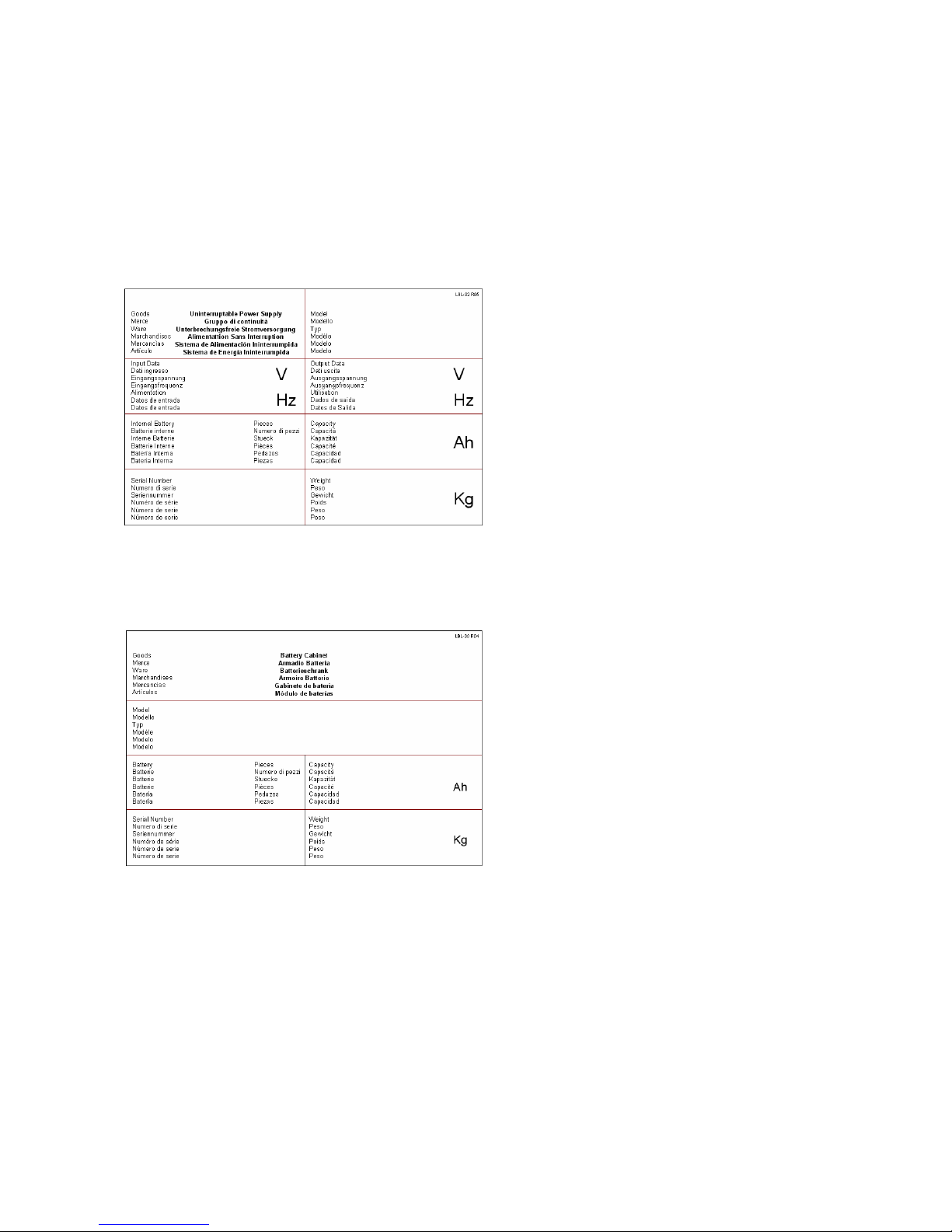
On receiving the goods you should verify the contents. On the front of the package you will find the sticker which
will allow you to identify the contents.
In the picture you can see the identity sticker which is placed on the packaging of the equipment:
1. Ups type
2. Specifies voltage and frequency input admittance
3. Specifies voltage and frequency output admittance
4. Specifies the number of batteries which may be
inside the machine
5. Specifies internal battery capacity
6. Specifies the serial number of the product
7. Specifies weight
In the picture you can see the identity sticker placed on the packaging of the battery:
1. Specifies the battery cabinet model
2. Specifies the number of batteries contained
3. Specifies battery capacity
4. Specifies the serial number of the product
5. Specifies weight
1.1 VERIFYING THE GOODS
After making sure that the goods are those required, please check that the equipment has not been damaged. In order
to do this you must verify the integrity of the p ackaging. After having removed the packaging check that the metal
panels have not been damaged during transport. If the goods are not compliant in any way please put them back in their
original packaging and send them back to the manufacturer.
Picture 1.1
Picture 1.2
1
2 3
4 5
1
3
5
7
2
4
6
________________________________________________________________________________
EVO STAR 60-800
9
2 HANDLIND, STORING AND POSITIONING
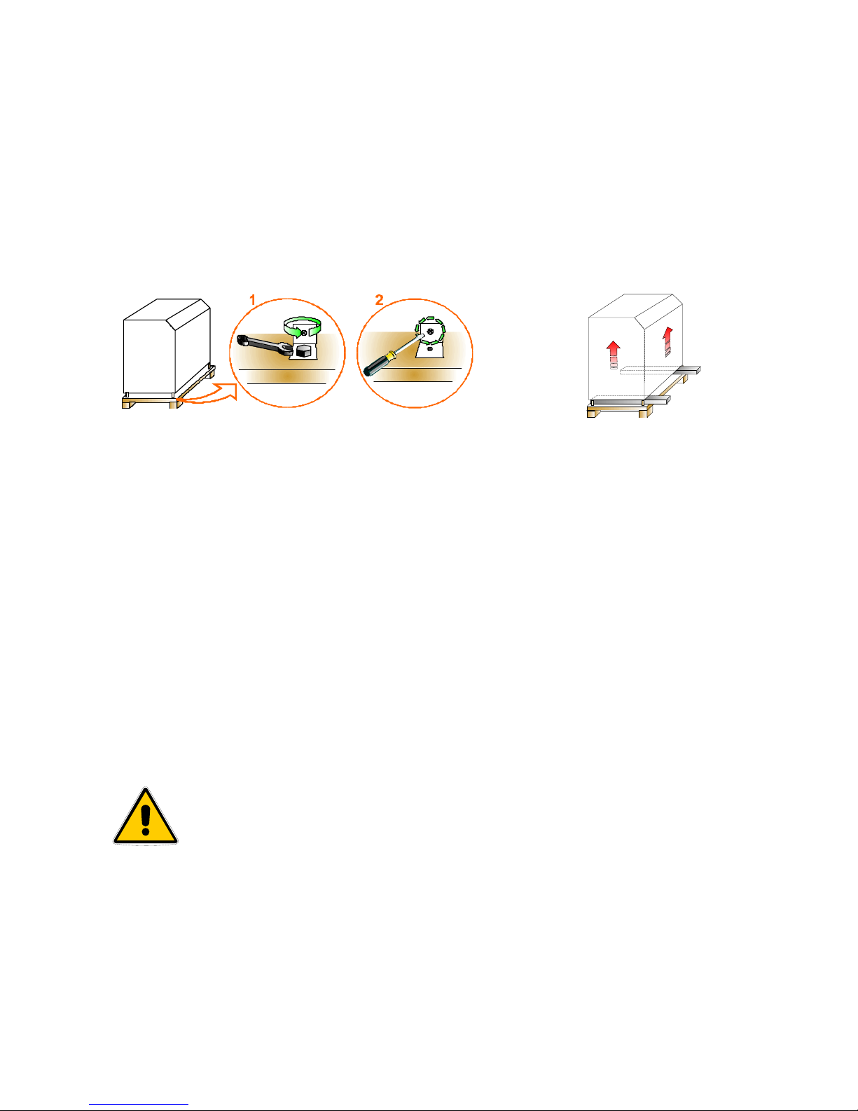
2.1 HANDLING
1. Remove the screws which fasten the machine to the pallet (Picture 2.1)
2. Remove the wooden pallet by using a lift truck and carefully place it on the floor (Picture 2.2)
3. For floor handling you will only need a transpallet with a suitable loading capacity
2.2 U.P.S. STORAGE
2.2.1 U.P.S.
If you need to store the UPS this must be protected from dust and dirt (even if it is well packaged). It must not be
exposed to the inclemency of the weather and the room shouldn’t be too humid (humidity below 90% noncondensing), nor should the UPS be exposed to sources of heat; room temperature should be between +1 e +40°C.
2.2.2 BATTERY CABINETS
If you need to store a complete battery cabinet, you should respect all the conditions mentioned in the previous
paragraph. You should also remember that battery discharge over time, even when not in use, therefore it is necessary
to recharge them every 4 months.
In any case, you must follow the manufacturers’ indications to store the batteries.
Non-compliance with these indications can cause an efficiency decrease and a
shorter life of the storage batteries.
Picture2.1
Picture 2.2
________________________________________________________________________________
EVO STAR 60-800
10
2.3 POSITIONING
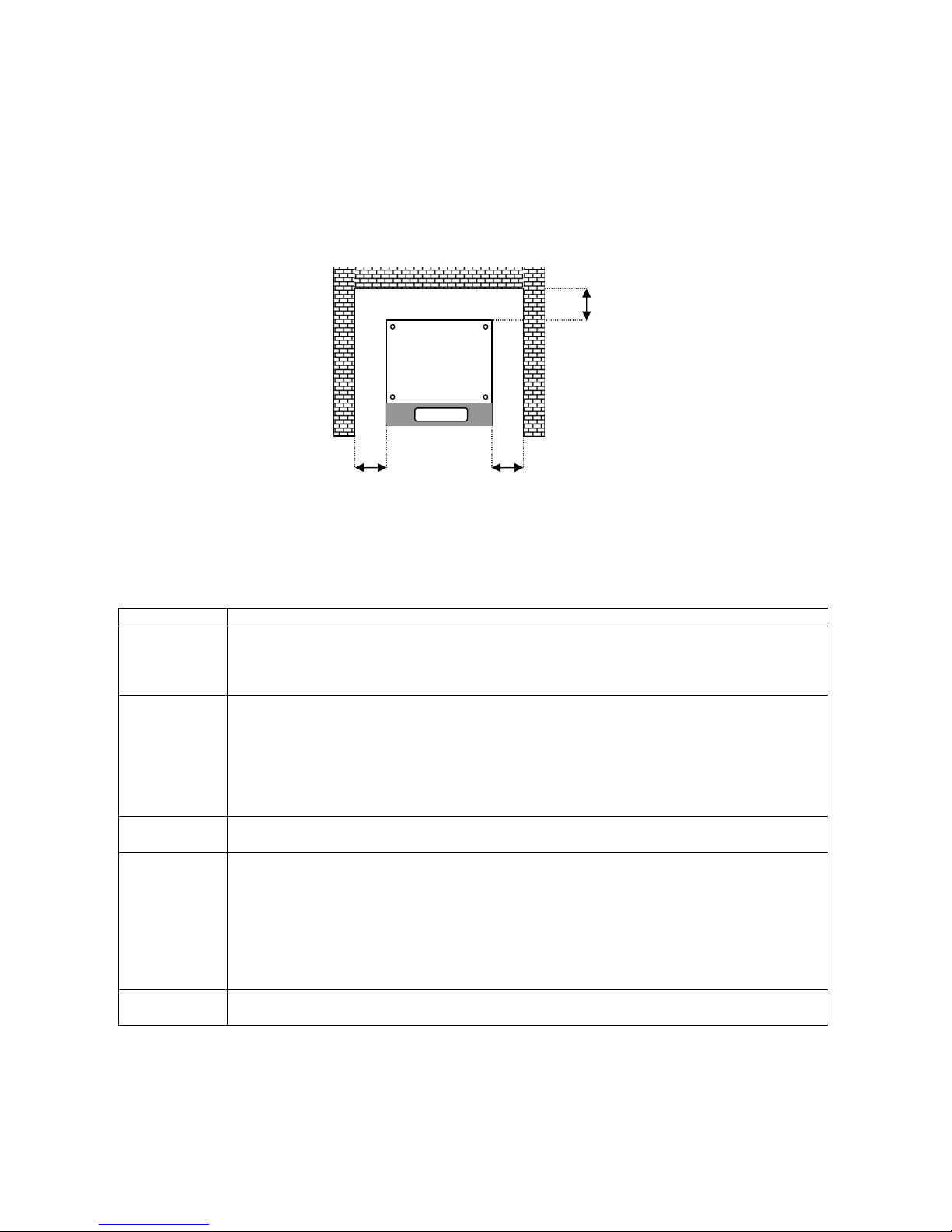
Installation space varies according to the size of the U.P.S and to the battery cabinet. A distance margin from the
walls of the room where the U.P.S. is positioned is also necessary for air circulation and ordinary/extraordinary
maintenance. Please refer to picture 2.3 for minimum margin distances. All models need a distance margin of at least
40cm either side or at least a metre from the ceiling.
2.3.1 CHOOSING THE ROOM
Element Requirements
Room access
• All the doors which the equipment has to go through in order to reach the chosen room have to
be large enough to allow the passage of the U.P.S (c harts 8) and its handling equipment. We
advise you to forbid access to the place where the U.P.S. and its battery cabinets are placed to
all non authorized users.
Room size
• Room space must be suitable to allow installation of the equipment and periodical and
extraordinary maintenance.
• When choosing the rooms please remember that the equipment must not be exposed to the
inclemency of the weather, to corrosive substances, to excessive humidity (humidity below 90%
non-condensing) or to very high sources of heat.
• The environment should not be very dusty. Please be very careful if you decide to carry out any
building work after setting up the machine.
Floor load
• According to the data in charts 8 you must check that the floors of the chosen rooms can support
the equipment’s weight.
Ventilation
• Room temperature should be preferably between 15° and 25°C
• Ventilators expel the heat dissipated by the U.P.S. into the air, therefore the room structure must
be suitable to guarantee sufficient aeration to eliminate the heat produced by the U.P.S.
• If room temperature does not comply with the recommended parameters or if air circulation in
the room is not adequate, you must supply the room with a ventilation system or, if this should
not be sufficient, install an air conditioning system.
Safety rules
• The rooms where the U.P.S. is installed must be equipped according to fire and safety
regulations.
Picture 2.3
40 cm
40 cm 40 cm
U.P.S. from 60 to 800 KVA
________________________________________________________________________________
EVO STAR 60-800
11
3 GENERAL DESCRIPTION
3.1 OPERATING PRINCIPAL
The U.P.S. is a continuous double conversion system with an output transformer. It works by carrying out a
continuous double conversion of the main supply, guaranteeing a constant stabilized supply of both voltage and
frequency, maintaining charge and control of the batteries (On-line functioning). In order to guarantee continuous
supply when the voltage of the electric system are no longer correct, power is drawn from the batteries. The system is
supplied complete with an automatic static commutator that connects the output to the back-up power supply, or if there
are special alarms such as the E.P.O. (Emergency Power Off) it shuts down completely output voltage.
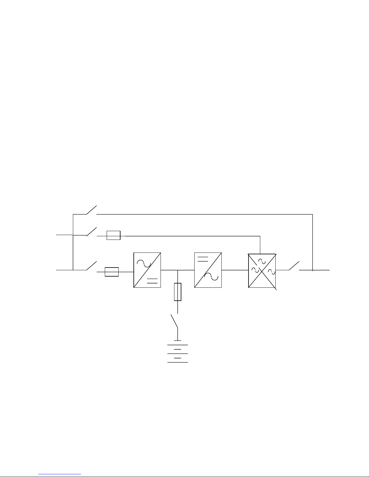
3.2 DESCRIPTION AND PARTS
During normal functioning (figura 3.1) the system takes power from the mains by means of the input terminal (1).
The voltage goes through the disconnecting switch (4) and the fuse board (6/a ) in order to reach the rectifier module
(7), exiting which is a continuous controlled voltage available to charge or maintain battery efficiency (cross fuse (6/b)
and battery switch (8)) and to the inverter input (10). This step is to generate a three-phase voltage, stabilized and
synchronized with the back-up voltage. The static commutator (11) selects the power source to power the load, usually
on inverter (10). If there is an increase of output current or with specific alarms, the device (11) will commutate to the
emergency supply maintaining output continuity. If transferring takes place, output continuity is allowed by the
synchronism of the voltages generated with the emergency voltage. If asynchronous commutation should take place
there will be a power “dip” for maximum 20 ms.
When the power supply is not in the set parameters, the equipment maintains output voltage by taking power fro m
the batteries (9). The system is provided with a current control that keeps the current inside set parameters in the event
of current overloaded.
4
3
2
5
6/a
7
6/b
1
10
8
9
11
12
13
Back-up line
By-pass Line
1. Power supply
2. Manual By-pass
3. Back-up line switch
4. Mains switch
5. Back-up fuses board
6. Fuses board
a) Mains b)Battery
7. Rectifier
8. Battery switch
9. Inverter
10. Static switch
11. Output switch
12. Output
Picture 3.1
1/A
RECT.
INV.
M.B.
I.B.
BATT.
________________________________________________________________________________
EVO STAR 60-800
12
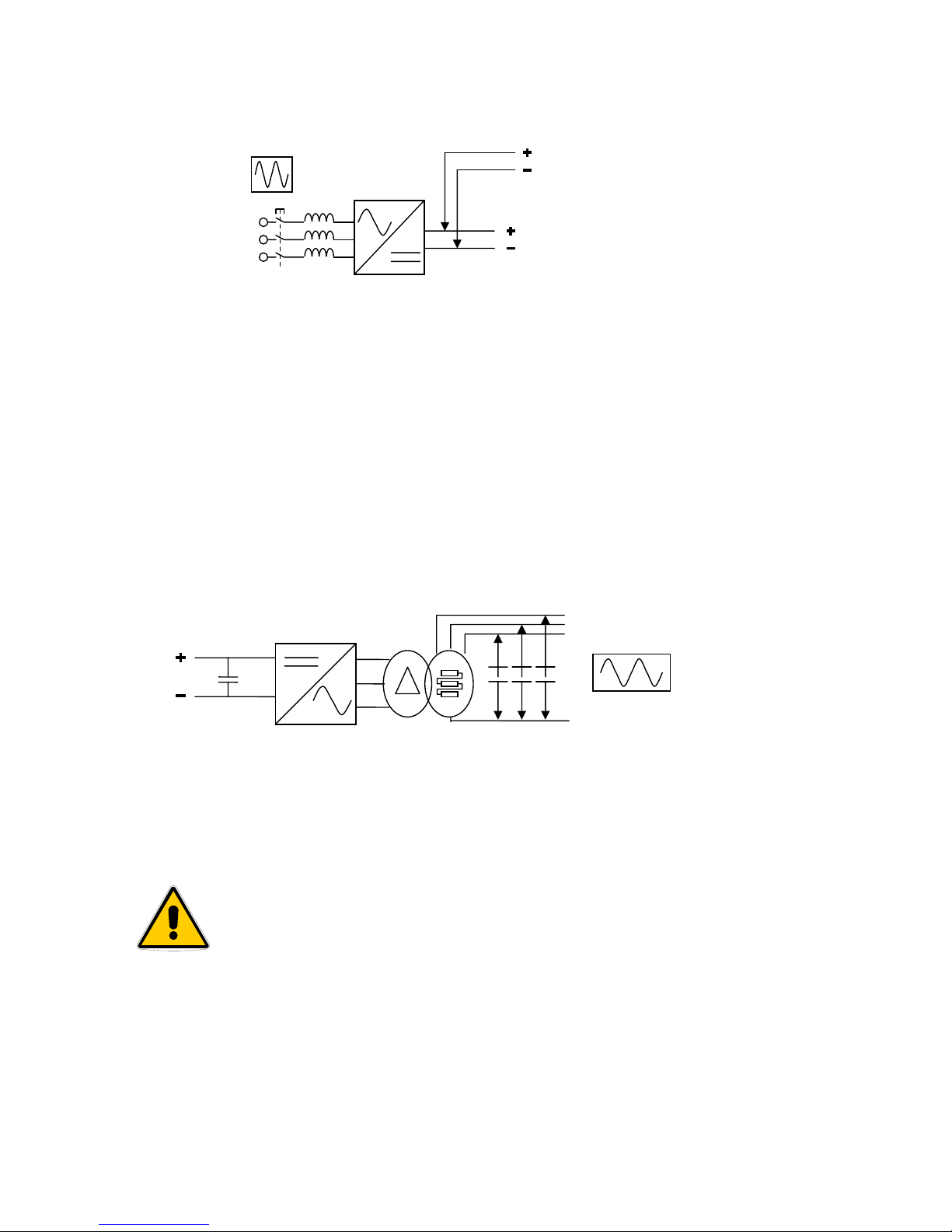
3.1.1 RECTIFIER
Rectifier indicated in picture with the abbreviation RECT, transforms alternating current voltage from main line to
direct current voltage. Its engineering allows, through a six pulse absorption to feed the inverter in its status of
maximum voltage output at the same time as the battery charge. Normally, direct current voltage is constantly set at
436Vdc (sustaining voltage), but when recharging the batteries, this voltage will be automatically limited b y a current
limiter.
In the following description the link from rectifier to inverter is defined as “Dc-link” and the voltage between its
poles is defined as “Dc link voltage”
3.1.2 INVERTER
The inverter, indicated in picture 3.1 with the abbreviation INV, has the role of transforming direct current voltage,
taken from the rectifier output, into sinusoidal voltage, which may be used by the user; This process is carried out by
using power semiconductors, piloted by a PWM signal, which through a transformer and a capacitance filter give us a
very stable three-phase voltage with a harmonic distortion lower than one unit.
The controlling logic of the inverter also controls output current intensity limiting it to a value which corresponds to
150% nominal current voltage.
3.1.2 STATIC COMMUTATOR
The static commutator indicated in picture 5 as B.S., is a commutator made with semiconductors which can select
which power source to connect appliances to. During normal functioning the U.P.S. output is taken at the inverter
output (U.P.S. on-line), but if there is an internal or external event it will commute to the reserve system.
Commutating from one source to another occurs without creating voltage
“dips” only with conditions of synchronism between inverter output and the
reserve system. If there is forced commuting, without synchronism, decided by
the user, this will occur with a voltage dip of max. 20 Sm.
Commuting Conditions on inverter:
1. Inverter switched on and working and synchronized with the
reserve system
2. Loss of system
3. Voluntary forcing through control panel
Commuting Conditions on reserve:
1. Malfunctioning of the inverter
2. Current overcharge
3. U.P.S. switched off
4. Voluntary forcing through control panel
Output voltage
L1 L2 L3
LN
Picture 3.3
Input voltage
To battery
To inverter
U
V
W
Picture 3.2
________________________________________________________________________________
EVO STAR 60-800
13
5. By-manual closing of the breaker
3.1.4 MANUAL BY-PASS
Il by-pass manuale, indicated in picture 3.1 as M.B., consists in a breaker which powers the critical load directly
from the main system. This device is particularly useful during ordinary/extraordinary maintenance, as it allows the
operator to deal with the internal circuits with a minimum risk of contact with voltaged elements.
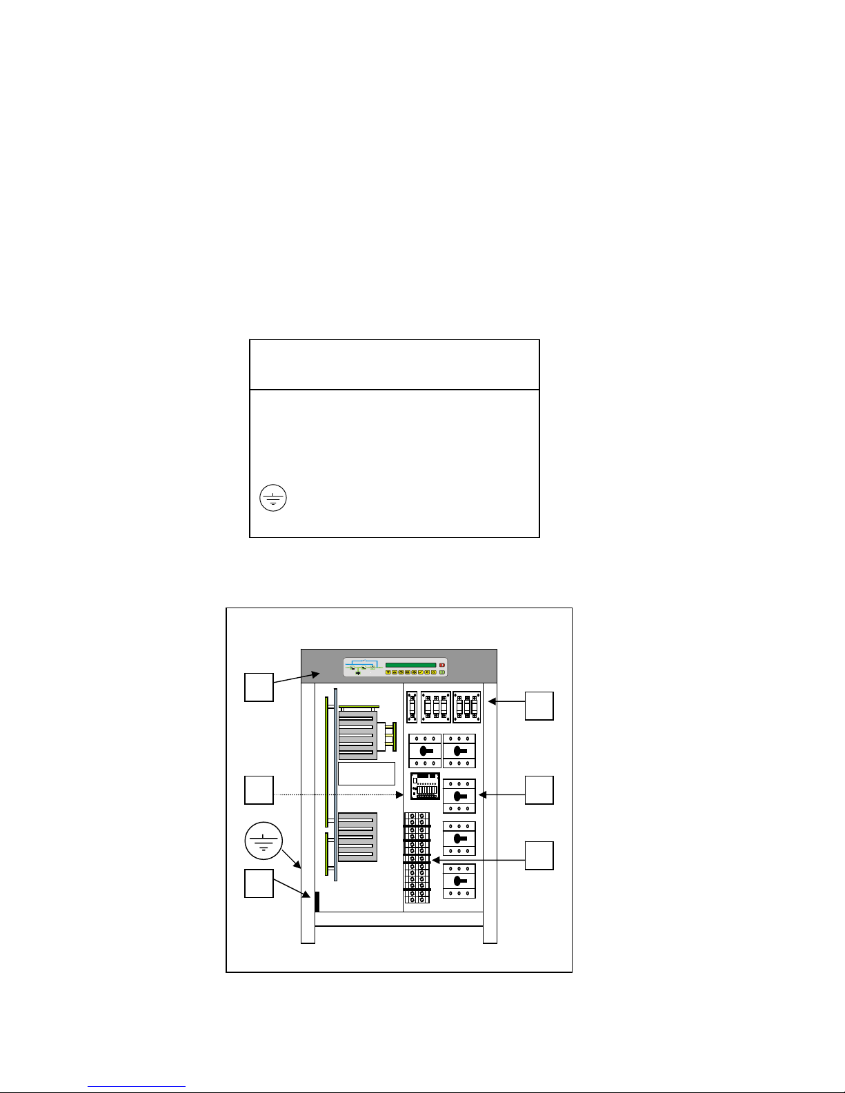
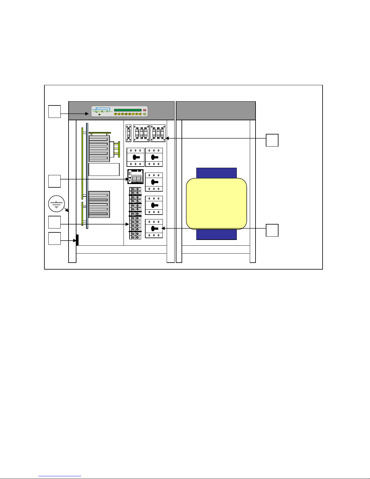
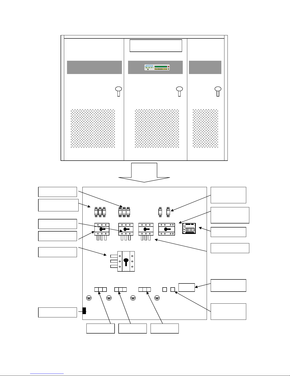
3.1.5 PART LAYOUT
It is important to be familiar with the parts that are necessary during the connection procedures before connecting
the equipment. In order to access the parts which will be described you must remove the “second access”, which is the
metal panel used to protect the inside parts of the U.P.S. and also to protect the user from accidental contacts with live
parts.
A = Display board
B = Relay board
C = Interface connector
D = Terminal
E = Breakers
F = Fuse cards
= Earthing
KEY
U.P.S. from 60 to 100 KVA
A
C
F
D
E B
Picture 3.4
________________________________________________________________________________
EVO STAR 60-800
14
U.P.S. from 120 to 150 KVA
A
B
C
D
E
F
Picture 3.5
________________________________________________________________________________
EVO STAR 60-800
15
Battery
connection
Mains switch
Reserve switch
Output switch
Battery fuses
Battery switch
Spare fuses
Neutral bar
Rectifier fuses
Relay board
RS 232
By-pass switch
Reserve Input Output
Picture 3.6
U.P.S from 200 to 800
________________________________________________________________________________
EVO STAR 60-800
16
3.1.6 BREAKERS
The U.P.S. has a system of breakers, which allows the user to carry out the necessary operations in order to use and
carry out maintenance on the equipment and to shut down the power supply if there is an emergency. A sticker placed
on the second access specifies the name of each switch near the switch itself. The by-pass switch contains a protection
device so, as it cannot be disconnected inadvertently. The user can remove this protection device if he/she decides to
carry out a manual by-pass.
1. MAINS SWITCH Break the mains supply, as specified in point 1 picture 3.1
2. RESERVE SWITCH Break the secondary power supply, as specified in point 7 picture 3.1
3. MANUAL BY-PASS Short-circuits the secondary input with the output
4. OUTPUT SWITCH Break the loading power supply.
5. BATTERY SWITCH Break, according to the model, one or both battery polarities.
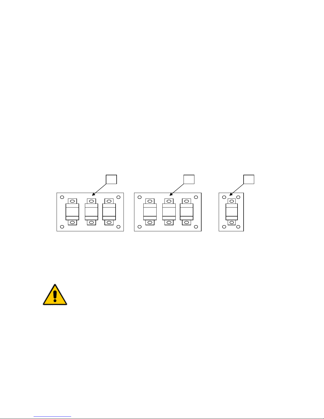
3.1.7 FUSES
The U.P.S. includes a system with two fuse groups, both counting three fuses each which are able to disconnect
electrical power input (points 1 and 7 picture 3.1), when the electrical power is not within the set parameters. The type
of fuse, which is used, guarantee quick intervention and therefore are a guarantee also for optimum protection of the
internal devices. Furthermore, there is also a fuse on the line, which connects the U.P.S. to the batteries (point 6 picture
3.1), both for internal and external batteries.
Board A, (picture 12), to the user’s left, protects the state of the rectifier input, board B , to the user’s right, protects
the reserve line. Whereas the single-fuse board C protects the battery line. In UPS over 150 KVA fuses are on
connection bars without board, for battery there are two fuses.
REPLACING THE FUSES
CAUTION! : ALL CONNECTING PROCEDURES DESCRIBED IN THIS CHAPTER
MUST BE CARRIED OUT BY AUTHORIZED ELECTRICIANS OR BY QUALIFIED
TECHNICIANS.
CAUTION! : BEFORE REPLACING THE FUSES YOU MUST CARRY OUT THE
MANUAL BY-PASS PROCEDURE WITH THE U.P.S. DISCONNECTED (CHAPTER 5)
A nut screw fastens each fuse. When replacing a fuse you must unscrew the two knurled nuts corresponding to the
fuse, which must be replaced, remove the washers, replace the fuse and put back the washers and the knurled nut in this
order. IMPORTANT spare fuses are supplied together with the U.P.S. If they have to be purchased please make sure
that they are extra-fast fuses for the current same as on machine so as to guarantee total protection.
A B C
Picture 3.7
________________________________________________________________________________
EVO STAR 60-800
17
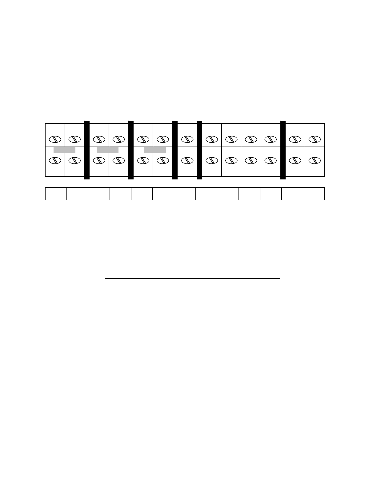
3.1.8 TERMINAL CONNECTORS
POWER UP TO 150 KVA
In all the models the terminal board is on the front of the U.P.S. protected by the second access.
It can be perpendicular or horizontal according to the model.
In any case, please refer to the alphanumeric specifications on the terminal board. The jumpers are arranged as in the
picture (highlighted in grey), and are used to short-circuit the main input and the reserve input. According to the type of
installation, you can remove them to connect the system to an auxiliary power source (back-up supply, generator).
U, V, W = Main input
U1, V1, W1, N1 = Reserve input
U2, V2, W2, N2 = Output
D(-),C(+) = Battery pole input. D(-) negative pole, C(+) positive pole.
In 100KVA device terminal D and C are double, in 120-150KVA also N1 and N2 are double
In this manual fase name U, V, W or R, S, T, or R, Y, B are equivalent.
POWER OVER 150 KVA
In the high power systems instead of using terminal boards for power connections a group of copper bars with
perforated ends are used. Therefore with the help of cable terminals, knurled screws and nuts a suitable connection for
the current values in circulation. As for the connection references please refer to the alphanumeric specifications on the
copper bars which respect the same specifications present on the terminal boards in equipment up to 200KVA.
U U1 V V1 W W1 N1 U2 V2 W2 N2 D(-) C(+)
Picture 3.8

________________________________________________________________________________
EVO STAR 60-800
18
4 CONNECTING THE U.P.S. TO THE MAINS
SUPPLY
CAUTION! : ALL CONNECTING PROCEDURES DESCRIBED IN THIS CHAPTER MUST
BE CARRIED OUT BY AUTHORIZED ELECTRICIANS OR BY QUALIFIED
TECHNICIANS.
CAUTION! : THE U.P.S. NEED A NEUTRAL WIRE. THE SYSTEM CANNOT WORK
WITHOUT IT.
4.1 COMPATIBILITY WITH THE POWER SUPPLY
The parallel connection to the public mains is normally allowed, as the U.P.S. is comparable to a passive charge.
The mains supply must supply a higher power than the U.P.S rated power as it has to take into account several factors,
such as:
1. Power absorbed by the output charge on the uninterruptible power supply
2. System efficiency
3. Power needed to charge the batteries
4. Input harmonic distortion
If you know the amount of power needed by the connected electrical equipment and you can evaluate the probable
expansion margins it is possible to make a first rough estimate of the power required. As for the power absorbed by the
batteries while charging, you can easily work out the power required by multiplying 436 ti mes 1/10 of the total battery
capacity (E.g.: For a 40A/h battery space, the power needed to charge the battery will be: 436 X (40 / 10) = 1,744 kW).
As for input harmonic distortion please remember that for the power supply the uninterruptible power supply is to be
considered as a non-linear load, which generates harmonic frequency currents multiples of the (50/60 Hz). In function
of the line impedance these create a harmonic voltage distortion. This latter value (total harmonic voltage distortion)
must not exceed the specific environment reference parameters. There are several ways of reducing this parameter: by
increasing the power supply, the section of power supplies cables or by choosing an interruptible power supply with
specific features (twelve-phase input, with filter).
4.2 INDIRECT POWER SUPPLY
4.2.1 TRANSFORMER
If you are using a system input isolation transformer this will reduce distortion effects and stop its diffusion in the
system. Therefore, apart from decreasing harmonic disturbance you can also probably avoid oversizing the power
supply line.
4.2.2 GENERATOR
Particular attention must be paid when sizing a possible input power unit; this has high output impedance, which is
defined on the rating plate as subtransient reactance of the alternator. This parameter makes a negligible harmonic
current distortion become a seriously disturbing element for the correct functioning of the U.P.S.
4.3 INPUT WIRE SIZING
When choosing the wir e you mu st b ea r in mind a technical, economical and safety evaluation. Technically speaking,
the main factors that affect wire sizing are voltage, current, overcurrent, temperature and how the wires are laid.
However, it is always a good rule to size the wires so as the voltage drop on each wire is below 3% of the applied
voltage. Particularly important is the sizing of the neutral wire especially when the U.P.S. is used to power unbalanced

________________________________________________________________________________
EVO STAR 60-800
19
loads or loads with strong harmonic distortion. Taking into account these last remarks, the enlargement factor must be
decided according to the size of the phase wire (usually 1,5-2 times).
4.4 PROTECTION OF THE U.P.S. OUTPUT LINE
The main electric distribution systems to which the U.P.S. can be connected are the TN-S and TT systems (pictures
4.1 and 4.2). If you do not have this type of equipment please talk to a specialized technician. The protection devices,
which can be applied to the U.P.S. output line, are against overcurrent and are differential. As for their size, please bear
in mind that if there is a power shortage the U.P.S. works on its own (disconnected from the main line), with a current
restriction equal to 150% of the rated current, therefore in order to protect against overcurrent you must choose a device
that is activated within this threshold. As for differential protections you must use type A differentials (for alternate
current and for switches with continuous components), which are low sensitivity (0,3–0,5-1 A).
4.5 CONNECTING THE SYSTEM
To connect the U.P.S. you must carry out the following procedures:
1. Open the front door, the key is attached to one of the supporting feet
2. Shutdown all breakers.
3. Verify the integrity of the by-pass breaker lock out
4. Make sure there is no voltage on the mains supply
5. Unscrew the second access panel setscrews and remove the panel
6. Connect the earthling wire for the mains to the earth bar
7. Connect the general mains to the U, V and W terminals of the U.P.S. ( in cyclic sense)
8. If the back-up supply mains are available disconnect the jumpers from terminals U1 and U, V1 and V, W1 and W,
then connect the back-up supply to the U1, V1 and W1 terminals
9. Connect the supply mains neutral wire to the N1 terminal
10. Connect the mains that power the connected electric equipment to U2, V2 e W2 terminals at the U.P.S. output
11. Connect the mains neutral wire that powers the connected electric equipment to the N2 terminal at the U.P.S.
output
12. If you need to connect external battery compartments please proceed to the following paragraph.
13. Replace the second access panel and fasten its screws.
14. Lock the front door with its key
Reassemble the side grids on the supporting base
N
PE
TN-S
L1
L2
L3
N
PEN
U.P.S
The TN-S system has the neutral grounded in a
specific point to which the system’s earth is also
connected with a separate protection wire.
TT
L1
L2
L3
N
U.P.S
The TT system has the neutral grounded in a
specific point and the system’s earth is connected
to an earth which is independent from the neutral.
This is the most used device at distribution level.
Picture 4.1
Picture 4.2

________________________________________________________________________________
EVO STAR 60-800
20
4.5.1 CONNECTION WITHOUT BACK-UP LINE
INPUT LINE
L1
L2
L3
LN
U-V-W
Mains
switch
By-pass
switch
Output
switch
N1
C+
D-
U2-V2-W2-N2
USER
L1
L2
L3
LN
Battery
switch
BATTERY
BOX
Picture 4.3

________________________________________________________________________________
EVO STAR 60-800
21
4.5.2 CONNECTION WITH BACK-UP LINE
Picture 4.4
MAINS LINE
L1
L2
L3
U-V-W
Mains
switch
By-pass
switch
Output
switch
N1
C+
D-
U2-V2-W2-N2
USER
L1
L2
L3
LN
Battery
switch
Battery
box
L1 RESERVE
L2 RESERVE
L3 RESERVE
LN RESERVE
BACK-UP LINE
Reserve
switch
U1-V1-W1

________________________________________________________________________________
EVO STAR 60-800
22
4.6 CONNECTING THE BATTERIES TO THE U.P.S.
CAUTION! : ALL CONNECTING PROCEDURES DESCRIBED IN THIS PARAGRAPH
MUST BE CARRIED OUT BY AUTHORIZED ELECTRICIANS OR BY QUALIFIED
TECHNICIANS.
CAUTION! : FOR SECURITY REASONS THE BATTERIES ARE TRANSPORTED WITH
SOME OF THE JUMPERS DISCONNECTED, THEREFORE PLEASE
REMEMBER TO RE-CONNECT THEM. SEE CHAPTER 7
4.6.1 CONNECTION TO A BATTERY CABINET
1. Make sure that the U.P.S. is switched off and that all switches are off
2. Unscrew the setscrew from the second access panel of the U.P.S. and remove it
3. Unscrew the setscrew from the battery cabinet roof and remove it
4. Make sure there is no voltage on the U.P.S. battery terminals and on battery box terminal
5. Connect the earthling wire to the earth bar of the U.P.S
6. Connect the earthling wire to the earth bar of the U.P.S
7. Connect the two wires, supplied to connect the external battery cabinet, to the C and D terminals of the U.P.S. (C=
positive, D= negative)
8. Connect the wires from the U.P.S. to the C and D terminals of the battery cabinet
9. N.B. Check and control all the connections of the jumpers inside the batteries of the battery cabinet
10. Make sure that the corresponding battery breaker placed on the U.P.S is off, then shut down the battery switch on
the cabinet
11. Using a multimeter verify the correct polarity on the U.P.S. battery terminals
12. Close the second access of the U.P.S. by fastening its screws
13. Close the battery cabinet roof by fastening its screws
14. Reassemble the side grids on the supporting base
4.6.2 CONNECTION TO A 180cm HEIGHT BATTERY CABINET
1. Make sure that the U.P.S. is switched off and that all switches are off
2. Unscrew the setscrew from the second access panel of the U.P.S. and remove it
3. Open the front access door of the battery cabinet with its key
4. Make sure there is no voltage on the U.P.S. battery terminals
5. Connect the earthling wire to the earth bar of the U.P.S
6. Connect the earthling wire to the earth bar of the U.P.S
7. Connect the two wires, supplied to connect the external battery cabinet, to the C and D terminals of the U.P.S. (C=
positive, D= negative
8. Connect the wires from the U.P.S. to the C and D terminals of the battery cabinet
9. N.B. Check and control all the connections of the jumpers inside the batteries of the battery cabinet
10. Make sure that the corresponding battery breaker placed on the U.P.S is off, then shut down the battery switch on
the cabinet
11. Using a multimeter verify the correct polarity on the U.P.S. battery terminals
12. Close the second access of the U.P.S. by fastening its screws
13. Reassemble the side grids on the supporting base

________________________________________________________________________________
EVO STAR 60-800
23
CAUTION! : THE U.P.S. AUTONOMY DEPENDS ON THE STATE OF THE BATTERIES; A
CORRECT AND PROGRAMMED MAINTENANCE IS
FUNDAMENTAL TO AVOID A BAD CONDITION OF THE
BATTERIES FROM HAMPERING U.P.S. FUNCTIONING WHEN
NECESSARY.
NOTE: WHEN BATTERIES ARE CONNECTED DON’T CLOSE BATTERY SWITCH IF UPS
IS OFF
4.7 MECANICAL OPERATIONS
4.7.1 OPEN FRONT PANEL
• Open the lock with supplied key
In model of power 120KVA -800KVA open door where the control panel is mounted
4.7.3 REMOVE SECONDARY DOOR
• Open front panel
• Remove screws on sides
• Remove ground wire fix on secondary door (remember to connect it before closing secondary door)
4.7.4 REMOVE ROOF
• Remove the four screws on roof
• Lift roof
• Remove ground wire fix under roof (remember to connect it before closing roof)
4.7.1 REMOVE SIDE DOORS
• Remove the four screws on side door
• Lift door
• Remove the four screws on roof
• Remove ground wire fix on door (remember to connect it before closing door)

________________________________________________________________________________
EVO STAR 60-800
24
5 STARTING-UP AND SHUTTING DOWN THE
MACHINE
5.1 STARTING-UP THE MACHINE
CAUTION! : IF THE BATTERY BREAKER IS CLOSED, BEFORE STARTING UP T2000,
THIS CAN CAUSE U.P.S DAMAGE.
5.1.1U.P.S with independent reserve line
1. Make sure that the wires are correctly connected respecting the cyclic sense of the phases U,V,W
2. Make sure that the “Manual By-pass” switch is turned off and blocked by its blocking device
3. Give power to the mains
4. Close the “Reserve switch” breaker, the display will turn on and the message “UPS STOPPED” will appear, all the
synoptic led’s will be red except led “H ” which remain green; wait till led “A” start flashing, if this does not
happen the supply voltage is not adequate or the cyclic sense of the phases is incorrect, therefore you must
disconnect the equipment, verify the connections and start this procedure again from the beginning.
5. Close the “Mains switch” and “Output switch” breakers, led’s “G and B” will turn green
6. Press the
button for about two seconds, on the display the message “switch on proced ure started” will appear,
if the steps of procedure have been followed correctly led “C” and led “E” will become green and the message
“UPS in alarm mode” will appear
7. Once you have carried out the turning on procedure and led’s “C” and “E” are green, it is possible to close the
“Battery switch” breaker and led “D” will be green.
8. If installation has been correctly carried out and the turning on procedure done successfully, the message “UPS in
normal operation operation” will appear and all the synoptic led’s will be green
9. Go to paragraph 5.1.2
5.1.2 First time starting-up
If the turning on procedure has been carried out for the first time we advise you to continue this procedure to verify the
real efficiency and to get familiar with the system
1. Select the language you wish to use by following the indications in the menu (diagram 1a/b)
2. Carry out the battery test (see 6.1.2.2) and verify the outcome
3. Carry out the complete by-pass procedure with the U.P.S. switched on (paragraph 5.1) and all operations to restore
the by-pass
4. Carry out a power shortage test by turning off the “Mains switch” and make sure that the U.P.S. goes into alarm
mode and that led D starts flashing and led F stays green (picture 1and 7) then turn on the “Mains switch” and
check that normal functioning has been restored.

________________________________________________________________________________
EVO STAR 60-800
25
5.2 SHUTTING DOWN
CAUTION! : THE FOLLOWING PROCEDURE WILL DISCONNECT THE LOAD!
In order to turn off you must:
1. Press for about 5 seconds the
button. On the display the message “TURN OFF UPS” will appear and leds
“C”,”E” and “F” (picture 17) will be red and the message “UPS STOPPED” will appear on display
2. Open “Output switch” and led “G” will be red
3. Open “Battery switch” and led “D” will be red
4. Open “Reserve switch” and led “A” will be red
5. Open “Mains switch” and the U.P.S. will be off completely
5.2.1 EMERGENCY POWER OFF SWITCH ( optional)
The Emergency Power Off switch (E.P.O.) allows, after pre-setting the function, U.P.S. shutdown totally or partially
in emergencies. Standard setting only has the totally turned off feature. If you want to modify this set up please ask for
a specialized technician to do. It is installed on the machine or on the remote control panel.
Specialised technicians can carry out After-sales installation only.
The switch on board the machine is on the right-hand side of the control panel; for the switch on the remote control
panel, please see picture 19.
Partial shutdown results in deactivating the static and the inverter, which in consequence will turn off all the electric
equipment connected to the system’s output, whereas the rectifier and battery will continue receiving charge current.
Total shutdown deactivates all functions (including the rectifier). During the emergency the message “WARNING
emergency shutdown” will appear on the control panel. There are two ways to restore normal functioning:
5.2.2 RESTORING FROM EPO
RESTORING FROM PARTIAL SHUTDOWN
:
RESTORING FROM TOTAL SHUTDOWN
:
Press switch off button
for about three
seconds then press the switch on button
for
about five seconds and wait till the end of the
shutdown procedure.
Press the switch on button
for about five
seconds and wait till the end of the shutdown
procedure.

________________________________________________________________________________
EVO STAR 60-800
26
6 ACTIVATING THE MANUAL BY-PASS
CAUTION! : IF YOU CARRY OUT THIS PROCEDURE INCORRECTLY YOU COULD
DAMAGE THE U.P.S.
THE MANUFACTURER DECLINES ALL RESPONSABILITIES FOR
DAMAGE DUE TO INCORRECT MANOUEVRING.
CAUTION! : DURING THE ENTIRE PERIOD OF FUNCTIONING IN BY-PASS MODE, THE
ELECTRIC EQUIPMENT CONNECTED TO THE OUTPUT OF THE
DEVICE WILL BE SUBJECT TO THE FLUCTUATIONS MAINS
VOLTAGE.
This manual operation transfers the load directly to the mains during maintenance or if the equipment breakdown.
6.1 ACTIVATING THE BY-PASS SHUTTING DOWN THE U.P.S
1. Verify that led “A” is green .
2. Press the
button for about 5 seconds; the message “ Turn off U.P.S ” will appear on the display and leds
“C”,”E” and “F” will turn red and the message “UPS stopped” will appear on the display
3. Turn on the “by-pass switch” breaker and led “D” will be red
4. Turn off the “Output switch” breaker and led “G” will be red
5. Turn off the “Reserve switch” breaker
6. Turn off the “Mains switch” breaker
7. Turn off the “Battery switch” breaker
RESTORING NORMAL FUNCTIONING FROM THE PREVIOUS CONDITION
:
1. Turn on the “Reserve switch” breaker, the message “UPS Stopped” will appear on the display, all the synoptic leds
will be red except led “H” remain green; wait till led “A” starts flashing, if this does not happen the supply voltage
is not adequate or the cyclic sense of the phases is incorrect, therefore you must disconnect the equipment, verify
the connections and start this procedure again from the beginning.
2. Turn on the “Main switch” e “Output switch” breakers, led “B” and led “G” will be green
3. Turn off the “Manual by-pass” breaker.
4. Press the
button for about 2 seconds; the message “Switch on procedure started” will appear on the display, if
the procedure has been carried out correctly led “C” and led “E” will be green and the message “UPS in alarm
mode” will appear
5. Once you have carried out the turning on procedure and that led “C” and “E” are green, it is possible to close the
“Battery switch” breaker and led “D” will be green
6.2 ACTIVATING THE BY-PASS KEEPING THE U.P.S SWITCHED
ON AND BATTERY CHARGING
1. Verify that led “A” is green
2. Press keys F6 and F2 at the same time, using the scroll keys select “On reserve” and confirm your choice by
pressing F6; make sure that led “F” become yellow
3. Turn on the “Manual by-pass” breaker
4. Turn off the “Output switch” breaker

________________________________________________________________________________
EVO STAR 60-800
27
RESTORING NORMAL FUNCTIONING FROM THE PREVIOUS CONDITION
:
1. Make sure the led “F” is yellow
2. Turn on the “Output switch” breaker
3. Turn off the “Manual by-pass” breaker
4. Press keys F6 and F2, at the same time and wait until led “F” turns green
Picture 6.1
By-pass line
6/A
7
Auxiliary

________________________________________________________________________________
EVO STAR 60-800
28
7 CONTROL PANNEL
The user can communicate with the U.P.S. in the following ways:
1. Using the control panel on the front of the control board
2. Using relay interface
3. Using a Personal Computer connected to the U.P.S.
4. Using the remote control panel (Optional)
You can connect all these check tools described above to the same machine without creating interference or
incompatibility among the components. The use of photocouplers on all interfaces (except for relay interface)
guarantees galvanic separation of the interfaces remote controlled from the U.P.S. assuring all connected equipment
total protection from disturbance and interference.
7.1 THE CONTROL PANEL AND ITS FUNCTIONS
Panel check functions can be split into three main categories:
1. Monitoring
2. Diagnostic tools
3. Functioning mode configuration
In the interface system we refer to “elements”. For element we mean a group of components which concur to the
same function.
ELEMENTS DESCRIPTION
SYSTEM Includes the U.P.S. as a whole
RECTIFIER Includes devices for conversion from alternating to direct voltage
BATTERY Includes the device for energy storage
INVERTER Includes devices for conversion from alternating to direct voltage
BACK-UP This is the emergency mains supply
BREAKERS Includes all the breakers in the U.P.S.
Picture 7.1

________________________________________________________________________________
EVO STAR 60-800
29
7.1.1 MONITORING
Monitoring allows checking that all specific functions are within the set limits
ELEMENTS AVAILABLE MEASUREMENTS
U.P.S. System
Phase-phase output voltage
Phase-neutral output voltage
Output current
Inside temperature
Load percentage
Inverter
Phase-phase output voltage
Link DC voltage
Link DC current
Frequency
Rectifier
Input Voltage
Link DC voltage
Link DC current
Battery
Voltage
Current
Back-up
Voltage
Frequency
Chart 1
7.1.2 DIAGNOSTIC TOOLS
The diagnostic tools allow checking the U.P.S. functioning state, by checking for the presence of alarms in progress or
already activated and Battery State.
The available diagnostic tools are:
1. Event menu
2. History menu
3. Battery test

________________________________________________________________________________
EVO STAR 60-800
30
7.1.2.1 LED
Led Associated element Colour Meaning
green Back-up mains OK
Breaker is off (where is foreseen)
red
Incorrect input voltage
Incorrect frequency
A Back-up mains supply
flashing
Not synchronised
green Rectifier mains OK
red Rectifier mains alarmed
B Rectifier mains supply
flashing Incorrect cyclical sense
green Rectifier OK
Rectifier alarmed
C
Rectifier
red
Rectifier off
green battery OK
red Battery alarmed
D Battery
flashing Battery discharging
green inverter OK
Inverter alarmed
red
inverter off
E Inverter
flashing inverter current over 125%
green Static commutator on inverter
yellow Static commutator on back-up
F Static commutator
red Static commutator off or blocked
green Output voltage OK
Incorrect output voltage
red
Opened breaker
G Output voltage
flashing
Output current over the nominal
value
green Manual by-pass open
H By-pass
red Manual by-pass closed
Chart 2
7.1.2.2 EVENT AND HISTORY MENUS
The “EVENT” menu allows viewing of all the alarms in progress, whereas the “HISTORICAL” menu allows viewing
alarms which were active but which have already been restored. They are used when the alarm of the machine goes off
to locate the origin and the cause of the alarm and also to establish how serious the problem is. Both have an error code
and a short message. The historical menu also shows the date and the time the alarm went off.
1. The “error code” is the code which identifies the type of error shown by the system
2. La “ display message” shows the message that can be seen in the “EVENT” or “HISTORICAL” menu, that is, a
brief explanation of the reason for the alarm
3. The “seriousness” defines how serious the problem is:
Anomaly
: If the alarm is caused by a temporary event
User
: If incorrect or intentional manoeuvring by the user
causes the alarm
Failure
: If the alarm is caused by a system failure that can
be restored only by the user

________________________________________________________________________________
EVO STAR 60-800
31
SYSTEM
Error code Display message Description Seriousness
SY1 Inverter w/o load Inverter without load Anomaly
SY2 Load on back-up Load on mains Anomaly
SY3 Error out voltage Error in output voltage User /failure
SY4 High Temperature Temperature block Anomaly
SY5 Pretemp. alarm Critical temperature Anomaly
SY6 Error direct voltage. DC Link voltage error Anomaly
SY7 Mains error Power supply in alarm Anomaly
RECTIFIER
Error code Display message Description Seriousness
RC1 High Temperature High Temperature Anomaly
RC2 Cyclic sense error. Cyclic sense error. User
RC3 Rectifier Error Rectifier alarmed Failure
RC4 Boost charge Boost charge activity User
RC5 Voltage Error Error in mains voltage Anomaly
INVERTER
Error code Display message Description Seriousness
IV1 Inverter off Inverter off User / Anomaly
IV2 Desaturation IGBT Desaturation IGBT failure / User
IV3 Voltage Error Error in inverter voltage Anomaly / failure
IV5 Inv. Not synchronised Error in frequency synchronism Anomaly
IV6 Frequency error Frequency error Anomaly
IV7 Current > 125% Output Current > 125 % Anomaly
IV8 Current > 150% Output Current > 150 % Anomaly
IV9 High current Output Current outside parameters Anomaly
BACK-UP
Error code Display message Description Seriousness
RS1 Cyclic sense error. Cyclic sense error. User
RS2 Voltage Error Voltage Error Anomaly
RS3 Frequency error Frequency error Anomaly
BREAKERS
Error code Display message Description Seriousness
SZ1 Rectifier Error Rectifier breaker User
SZ2 Back-up error Back-up breaker User
SZ3 Output error Output breaker User
SZ4 By-Pass Manual By-pass User
SZ5 Battery error Battery breaker User
OP1 User mode Jumper in the relay board User
Chart 3
7.1.2.3 BATTERY TEST
CAUTION! : CARRY OUT THE BATTERY TEST ONLY WHEN THE MACHINE IS IN
NORMAL MODE OPERATION
The battery test allows the user to check battery connection quality and fuse condition. To carry out the test press the F6
and the F3 keys together then press F6 to confirm, as specified in diagram 1. The test lasts for a minute, during which
the U.P.S. takes the necessary energy to maintain its load from the battery. At the end of the test the result will appear
under the form of “Good Battery” or “Bad battery”.

________________________________________________________________________________
EVO STAR 60-800
32
CAUTION! : PLEASE NOTE THAT SPECIALIZED TECHNICIANS MUST CARRY OUT
THE PROCEDURES DESCRIBED BELOW ONLY
In the second case, that is to say “Bad batteries”, you must check the fuses on the connecting line between the U.P.S
and the battery cabinet. To do so you must measure the direct voltage on the battery fuse ends which are placed in the
U.P.S and in the battery cabinet with a multimeter. If the fuses are not damaged, voltage measurement is next to zero.
If the fuse check is positive, it means that the connected batteries are no longer suitable to maintain the load if there is a
power shortage.
7.1.3 FUNCTIONING MODE CONFIGURATION
This product gives you the possibility of configuring the functioning mode in order to modify its use.
7.1.3.1 BATTERY CHARGE MODE
Press the F6 key and the starting key as specified in diagram 1a/b. These keys activate the starting procedure which
consists of the starting of the rectifier only. This makes it possible to charge the batteries through the terminal contacts
C and D. This function is very useful if the U.P.S. is not used for a long time and therefore needs complete battery
charge.
7.1.3.2 FORCING ON INVERTER MODE
To activate this function press the F6 key and the F2 key together as specified in diagram 1a/b. This will mean that the
system output will constantly be connected to the inverter, thus excluding the emergency mains supply. While the
system is starting up it provides output energy only when the voltage level has reached set parameters. With this type of
forcing it is possible to start up the U.P.S. without the emergency mains supply.
7.1.4 SYSTEM AUTONOMY
During a black-out on display will appear autonomy of the system.
This time is a function of battery voltage, and load percentage.
7.1.5 BUZZER
Internal buzzer is associated to summary alarm, you can turn on or turn off it press F2 key. If you turn of f buzzer it
will be off as long as all alarms off and other alarm start.

________________________________________________________________________________
EVO STAR 60-800
33
7.1.6 STRUCTURE MENU

________________________________________________________________________________
EVO STAR 60-800
34

________________________________________________________________________________
EVO STAR 60-800
35
7.2 OTHER INFORMATION
Button
PR1 STOP
PR2 HELP F1
PR3 BUZZER F2
PR4 MEASURE F3
PR5 HISTORY F4
PR6 DATE TIME F5
PR7 CONFERMATION F6
PR8 UP F7
PR9 DOWN F8
PR10 START
PR11 Reset of board
Clear history without reset:
This operation is possible only if U.P.S. is in normal mode
Press F4 key to enter historical menu
In this menu F7,F8 can select undermenu
Press F6 key to enter menu and press F4 to escape
Enter into menu “Clear History”, is possible erase every message in history buffer. If you wont this press F6 key to
confirm erase, or press F3 to escape without erase.
Relay programming:
This operation require A11 board on machine
Press F3+F6 keys, change with F7, F8 program menu keys and select with F6 key “Relay programming” or press F3
key to escape
In the secondary menus you can select a relay (F7,F8, keys) press F6 key to confirm or F3 to escape.
In relay menu there are all the alarms possible for relay, selected alarm are marked by “*”, select desiderate alarm
and press F6 to confirm or F3 to escape without modify. Is possible to select more alarm for one relay. The complete
default relay configuration is in chapter 11. Note: the leds on A11 turn on when one alarm associated to relay is in
progress.
Other measure
From version software 3.01 on are available on measure menu indication about output power, active power, power
factor.
Working time
It is possible to read information about working time of machine and are available calcs of the hours in the
following mode
On inverter: total time in which load was supplied by UPS
On reserve: total time in which load was supplied by back-up line
On battery: total time in which load was supplied by UPS and UPS supply by batteries
Summary time: UPS on time.

________________________________________________________________________________
EVO STAR 60-800
36
8 OTHER BOARD
8.1 INVERTER
Board control: AC voltage generate to UPS, output voltage, static switch, internal temperature and syncro.
LED
LED
Number Name Description Colour
DL1 SIOK
Syncro between back-up voltage and inverter voltage. When this occours
UPS can transfer supply of load from one line to other without discontinuity.
If there is forced commuting, without synchronism, decided by the user, this
will occur with a voltage dip of max. 20 ms.
green
DL2 FIOK
Back-up frequency in tolerance range.
greem
DL3 RPSKO
Cyclic sense error on back-up line
red
DL4 VRKO
Back-up voltage out of tolerance
red
DL5 VROK
Back-up voltage OK
green
DL6 PRTEM
Inside the UPS there are two temperature probes, these are mounted on
heatsink with power modules, one is front of air input, secondi is on back
near air output. The first is temperature alarm, the second is prealarm, hair
flow go from front to back. Probe turns on at 70°C.
yellow
DL7 HITEM
If air flow is too hot probe turn on and temperature alarm is set. Probe turns
on at 90°C. Temperature alarm will turn off UPS and load supply is
transferred to back-up line.
red
DL8 DESAT
One or more module IGBT have desaturation
red
DL9 START
Inverter on
green
DL10 VDCKO
DClink voltage out of range
red
DL11 F0OK
Phase zero ok
green
DL12 FRAL
Problem on control of frequency generate by device
yellow
DL13 VIOK
Inverter voltage ok
green
DL14 I125%
Output current overload, over 25% of nominal value
red
DL15 II150%
Output current overload, over 50% of nominal value
red
DL16 LMAINS
Load supply by back-up line
green
DL17 VUKO
Output voltage low, under 20% of nominal value
red
DL18 LINV
Load supply by inverter voltage
green
DL19 IUMAX
Output voltage over max value
red
8.2 RECTIFIER
Logic rectifier board controls: DC voltage generate by AC/DC conversion, driver of rectifier’s SCR, input current and
battery current.
LED
LED
Number Name Description Colour
DL1
SUPP Input voltage board OK
green
DL2
PHMKO Input order phases wrong
red
DL3
BTEST Battery test in progress
yellow
DL4
RDON Rectifier on
green
DL5
BOOST Battery boost (not used)
yellow
DL6
HTEMP Temperature high
red
DL7
VMKO Mains voltage out of range
red

________________________________________________________________________________
EVO STAR 60-800
37
8.3 POWER SUPPLY
This board supplies all other boards taking energy from A08 board and from DC voltage when rectifier is on. So it can
supply the boards in case of input line black out.
LED E FUSES
LED
Number Name Description Colour
DL1
VAL Input board voltage ok
green
DL2
+12v Output board voltage ok
green
DL3
-12v Output board voltage ok
green
DL4
+5v Output board voltage ok
green
FUSES
FU1 = + DC fuse on connection with positive pole of DC voltage
FU2 = - DC fuse on connection with negative pole of DC voltage
Fuses are 6,3*32 2A
8.4 DRIVER IGBT
This board supply driver signal for IGBT modules.
LED
LED
Number Description Colour
DL1
Isolated A -8V supply voltage
Verde
DL2
Isolated A -15V supply voltage
Verde
DL3
Isolated B -8V supply voltage
Verde
DL4
Isolated B +15V supply voltage
Verde
8.5 FUSES BOARD
REPLACING THE FUSES
CAUTION! : ALL CONNECTING PROCEDURES DESCRIBED IN THIS CHAPTER MUST
BE CARRIED OUT BY AUTHORIZED ELECTRICIANS OR BY QUALIFIED
TECHNICIANS.
CAUTION! : BEFORE REPLACING THE FUSES YOU MUST CARRY OUT THE MANUAL
BY-PASS PROCEDURE WITH THE U.P.S. DISCONNECTED (CHAPTER 5)
A nut screw fastens each fuse. When replacing a fuse you must unscrew the two knurled nuts corresponding to the
fuse, which must be replaced, remove the washers, replace the fuse and put back the washers and the knurled nut in this
order. The fuses used are extra-fast fuses for the current specified in charts 9a and 9b.
If you replace fuses with models different to the above described the guarantee will no longer be valid.
8.6 STATIC DRIVER
Static switch is made by SCR, this board drives them.

________________________________________________________________________________
EVO STAR 60-800
38
8.7 TRANSFORMER BOARD
These boards supply A04, voltage probes for logic board and fans.
The positioning of boards on device is as in picture 8.2, on CN1 enters AC voltage to measure, from CN2 comes out a
signal proportional to this voltage, CN3 supplies voltage to A04, CN4 supplies AC voltage to fans (CN4 on A08
position 1 supplies A04).
Picture 8.1
FU1
FU2
FU3
FU4
CN1 CN4
CN2
4) Output system
3) Back-up line
2) Output Inverter
1) Input Mains
Picture 8.2
CN3

________________________________________________________________________________
EVO STAR 60-800
39
Position
Description
1 Mains input voltage
2 Inverter output voltage
3 Back-up input voltage
4 Static output voltage
Fuses
0.5A 250V 6x32 (FU1 FU2 FU3)
0.2A 250V 6x32 (FU4)
8.8 RECTIFIER DRIVER
This board takes signal generated from rectifier A03 and transforms it in signals for SCR driver, so it’s possible AC-DC
conversion.
8.9 HALL BOARD
On machine there are eight hall probes, you can find them by flat and wire on which they are positioned
Position Wire Flat Jumper Description
1 13 FC3 Jp1 Positioned on wire from DClink to battery switch, it is used to
read Dc current from Dc to battery
2 13 FC3 Jp2 Positioned on wire to connect retcifier to inverter, it is used to
read current between these parts
3 20 FC14 Jp1 Measure current on phase R generate to inverter
4 23 FC14 Jp2 Measure current on phase S generate to inverter
5 26 FC14 Jp3 Measure current on phase T generate to inverter
6 32 FC17 Jp1 Measure output system current on phase R
7 33 FC17 Jp2 Measure output system current on phase S
8 34 FC17 Jp3 Measure output system current on phase T

________________________________________________________________________________
EVO STAR 60-800
40
8.10 RELAY BOARD
The relay board is a user interface system, which allows viewing of the U.P.S. State through eight diverters, one
standard and seven optional, which are controlled. These contacts are used especially to start up the acoustic and visual
alarm systems when specific events occur. The types of relays, which are used, allow connecting functioning electric
equipment up to 250V alternating, with a 5A maximum absorption.
For each relay we can associate an alarm or we keep the standard setting. In case of particular requirement for relay
programming, to aks our engineers.
The position of this board varies according to the model, but in any case once you have removed the second access it is
always visible and accessible to the user.
RELAY RELATED STATE (STANDARD)
CONTACT
NUMBER
AVAILABLE
CONTACTS
ALARM CONFIGURATION
TABLE
1 N.C.
Output current > 150%
Load on
reserve
A RECTIFIER STARTED(OPTIONAL) 2
3 N.A.
Output current > 125%
Load on
inverter
4 N.C. Frequency alarm
Reserve frequency
KO
B INVERTER STARTED(OPTIONAL) 5
6 N.A. Sincro alarm
Reserve voltage
KO
7 N.C. Zero phase alarm
Wrong reserve
phase seq.
C
LOAD ON RESERVE
LINE(OPTIONAL)
8
9 N.A. V Inverter bad Main voltage
KO
10 N.C. IGBT Desaturation Boost charge
D LOAD ON INVERTER(OPTIONAL) 11
12 N.A. Inverter on Rectifier ON
13 N.C. Summary alarm
Rec. Phase seq.
Wrong
E
PRE-ALARM
TEMPERATURE(OPTIONAL)
14
15 N.A. VDC < 350V High temp.
Rectifier
16 N.C.
Iout > Rating current
Relay board
jumper
F
TEMPERATURE ALARM OR
DESATURATION(OPTIONAL)
17
18 N.A.
Power supply alarm
Battery switch
19 N.C. DC Link fault By-pass switch
G
LOW BATTERY
VOLTAGE(OPTIONAL)
20
21 N.A. Pre Temp. Alarm Output switch
22 N.C. High Temp. Alarm Reserve switch
H
OUTPUT CURRENT >
125%(OPTIONAL)
23
24 N.A. Voltage out KO Main switch
CN2
CN3
Led
Jumper
A B C D E F G H
Terminal
CN1
Picture 18

________________________________________________________________________________
EVO STAR 60-800
41
Chart 4 (N.C.= Normally closed N.O.= Normally open)
The states associated to the relay are standard, but a specialised technician according to necessity can modify them. You
can verify the state of the relays with the led’s (picture 18) which are placed above each relay.
8.11 RECTIFIER FILTER
This board is a RC filter on DC voltage generated from rectifier.
8.12 BATTERY FUSE
It is on battery connection line. It is placed on A13 wire to protection against battery overcurrent.
Jumper M2. It
must be
removed if you
in
sta
ll rem
ote
Jumper R9. It
must be removed
if you install
remote EPO
JP1: A01 program
Connection from A14
Picture 8.4

________________________________________________________________________________
EVO STAR 60-800
42
9 BACK-UP LINE
Back-up line (sometime named reserve or auxiliary line) is available only on demand, with this line is available an other
input line.
10 REMOTE PANEL (optional)
The remote panel is an extension of the synoptic supervision (picture 17 plus char t 1); this is particularly useful when
you need to monitor machine functioning in a remote place. Furthermore, it is possible to supply it with an E.P.O.
switch (chapter 4.2.1). This device is composed of two main parts, one interface board inside the machine and an actual
synoptic which should be installed in a place of your choice to carry out monitoring at a maximum distance of 25
meters.
The synoptic is in a wall box with a bottom cable passage.
Please remember that the remote panel needs a 220-240V/50-60Hz power supply, which is to be taken only from the
U.P.S. output.
A specialized technician is recommended to install these devices.
Please refer to picture 7.1 for the meaning of the state of the leds.
Picture 10.1
E.P.O.
Switch
(optional)
Cable
p
assage

________________________________________________________________________________
EVO STAR 60-800
43
INSTALLATION OF REMOTE PANEL WITHOUT E.P.O.
To install this board please follows the procedures below:
Make sure that the U.P.S. is off and that all the switches are off (if the U.P.S. is already operative please proceed to bypass setting chapter 5)
Unscrew the set screws from the second access panel of the U.P.S. and remove it.
Check if there is an interface board (picture 20); (present only if requested before purchase). Its position varies
according to the different models but it is always viewable and accessible by the user.
If there is a board please go directly over, otherwise continue with the following procedures.
Insert the four supports for the printed circuit in the holes
Fasten the board as specified in picture , to the supports you have just inserted
Create a connection with the supplied flat-cable between connector A and connector CN3 on the relay board ,
respecting polarity, that is to say, the coloured wire level with the sign on the board
1 14
B
A
Picture 10.2
Picture 10.3

________________________________________________________________________________
EVO STAR 60-800
44
Position the remote panel in the place chosen for monitoring
Proceed to connect power supply (220-240V/50-60Hz) to the M3 connector of the PCB board, remembering to leave
the central terminal free
Carry out connection between interface connector indicated with the letter B (picture 20) and the M1 connector . Bear
in mind that the connection must be carried out symmetrically (pin1-pin14, pin2-pin13, . . ., pin13-pin2, pin14-pin1)
Close the U.P.S second access by fastening the screws
Continue the starting procedure (if already operative restore functioning from U.P.S by-pass following the relative
instructions)
The remote panel kit is composed by:
N 1 remote panel
N 1 interface board
1. Mount remote panel in a place designed to monitoring
2. Supplies it (220-240V/50-60Hz) from socket M3 (picture 10.2), where pin1 is the phase, and pin 3 is a
neutral, pin 2 must be void
3. A14 and A16, must be connected by 14 poles wire not supplied. Corrispondance between A14 and A16
connector is as follows:
A14
1 2 3 4 5 6 7 8 9 10 11 12 13 14
A16
14 13 12 11 10 9 8 7 6 5 4 3 2 1
M1 M2
M3
1 14
Picture 10.4
Picture 10.5

________________________________________________________________________________
EVO STAR 60-800
45
INSTALLING THE REMOTE PANEL WITH E.P.O.
CAUTION! : FOLLOW THE INSTRUCTIONS VERY CAREFULLY. ANY MISTAKE WILL
CAUSE AN OUTPUT VOLTAGE DROP.
To carry out the installation of a remote panel with E.P.O., you must first carry out all installation procedures for the
normal remote panel, as in paragraph 6.4.1 then check the actual efficiency of the remote panel by checking that the
leds respect the colours on the control panel.
After doing so please carry out the following instructions:
Make sure that the U.P.S. is off and that all the switches are off (if the U.P.S. is already operative please proceed to bypass setting chapter 5)
Unscrew the set screws from the second access panel of the U.P.S. and remove it.
Using cutting nippers cut the jumper as shown on the relay board (picture 18)
Turn on the “Reserve switch” disconnecting switch, the message “UPS Off” will appear on the display and all the
synoptic leds will turn red except for led “H” which will be green; wait till led “A” (picture 17) starts flashing
Turn on the “Main switch” disconnecting switch, led “B”(picture 17) will turn green
Press the
button for about two seconds, the message “Starting up procedure started”, and if the procedure has been
carried out correctly led “C” (picture 17) and led “E” will turn green in sequence and the message “UPS alarmed” will
appear on the display
Press keys F6+F3 with the arrows F7-F8 select “Level of EPO”, press F6 to confirm, select “Stop completed” and press
F6.Press F3 to go back to the main menu
Press the E.P.O. switch on the remote panel and check that the emergency butto n actual l y works (leds C, E, F picture
17) chapter 6.1 must turn red and the message (Emergency EPO block) will appear
Reset the switch
Continue the starting procedure (chapter 4) (if already operative restore functioning from U.P.S by-pass following the
instructions in paragraph 5)

________________________________________________________________________________
EVO STAR 60-800
46
11 EMERGENCY POWER OFF
Partial shutdown: results in deactivating the static and the inverter, which in consequence will turn off all the electric
equipment connected to the system’s output, whereas the rectifier and battery will continue receiving charge current.
Total shutdown deactivates all functions (including the rectifier). During the emergency the message “warning
emergency shutdown” will appear on the control panel.
CAUTION!:
THE FOLLOWING PROCEDURE WILL DISCONNECT THE LOAD
EPO (Emergency power off) is used to turn off rectifier, inverter and static bypass as soon as epo contact is close.
Load is not supplied. EPO is useful in emergency situations (for example fire) to disconnect load from supply line.
11.1 EPO TYPE
11.1.1 EPO ON CONTROL PANEL
If EPO is installed on machine, it is always visibile on control panel.
11.1.2 EPO ON REMOTE PANEL
If EPO is installed on remote panel, it is always visible on this. So it is possible to force epo from the remote place.
11.2 PROGRAM EPO
By control panel is possible to program the behaviour of EPO.
Insert J1 on A11
Press F6+F3 keys and enter menu
By F7, F8 keys select EPO and press F6 to confirm
By F7,F8 keys select behaviour type
Is possible to select between three modes:
Not active
Partial shutdown
Total shutdown
Esc to program menu and remove J1 to A11
11.3 RECOVERY FROM EPO
Press epo button and then press start green button on control panel

________________________________________________________________________________
EVO STAR 60-800
47
12 RS232 SERIAL CONNETCION
Serial port uses RS232 standard.
Futhermore the adapter is able to use other interface protocols:
- SNMP for UPS wire connection
- USB
- RS485 (half-duplex o full- du pl ex )
It’s possible by server and enterprise management SNMP (Simple Network Managing Protocol), or via world wide
web to make a remote monitoring and management. Connect U.P.S. in LAN/WAN, with usually “Ethernet” connection
(able as optional interface, or RS232), is possible monitoring UPS as any other wire elements with its IP address.
Note:
All connected devices with independent supply, must be supplied by UPS protected line
Wire for RS232 must be serial male DB9 socket on side U.P.S (connect to B24), and serial female DB9 socket on
side PC.
Max distance for connection is about 20 mt.
Connection pin of connection wire
Computer Ups
Female DB9 Male DB9
Pin 2 Pin 9
Pin 3 Pin 6
Pin 5 Pin 7

________________________________________________________________________________
EVO STAR 60-800
48
13 SNMP
13.1 SNMP
SNMP adaptor is able to monitor measure and alarms of UPS. It needs to the control kit B00. Shutdown software
can advise the user in case of main fault, can control automatic pc shutdown if battery autonomy is turning off.
Monitoring software can read in real time measures on device (output voltage, input voltage, temperature, etc).
Is possible to know alarms, voltage break down, anomalies that took place during working time or in progress, it is
possible to send e_mails, system shut down etc.
13.2 ISTALLATION
Kit Mini NetAgent
It is suggested a extension wire to connect B24 and device
Extension wire
Female DB9 Male DB9
Pin 9 Pin 9
Pin 6 Pin 6
Pin 7 Pin 7
14 OUTPUT FREQUENCY
CAUTION!:
It is necessary turn off the’U.P.S and disconnect it from load
It is possible to set input/output frequency to 50 Hz or 60 Hz. In order to change frequency ask a qualified
technicians
Don’t turn on the U.P.S. if input and output frequency are not equal
.
Frequency conversion is an operation made to F2000 devices
that are not the subject of this manual.

________________________________________________________________________________
EVO STAR 60-800
49
15 BATTERIES
The system guarantees uninterruptible power by using buffer batteries directly connected to the AC/DC
conversion output. A periodical check of the Battery State will prevent unpleasant mishaps that may occu r if there is a
power shortage, such as short autonomy or in extreme cases even non-intervention of the system with consequent load
loss. If storing battery cabinets batteries please remember to recharge them every four months (chapter 6.1.3.1), in
order to guarantee the best maintenance possible.
For transport safety the batteries inside the cabinet are disconnected in some points to discontinue circuit continuity,
therefore you must restore these connections when installing the batteries.
As already mentioned system autonomy depends on the type of battery used and, above all, on their capacity.
Battery capacity is expressed in ampere/hour, from this parameter you can work out system autonomy. This expresses
the amount of current delivered in a given time interval, discharging a storage battery at a given condition (discharge
current), until it reaches a set voltage. For example, a 50 Ah capacity can deliver 2,5 A for 20 hours. Excessively hot
temperatures, over 40°C, can drastically reduce battery life, due to plate corrosion caused by an increase of acid
aggressiveness. However, the system has a device, which can reduce working voltage according to the temperature, thus
improving battery life.
The discharge characteristic varies according to the make and model but it may be compared to the graph above.
The buffer system used is composed of a string of 32 batteries connected in series. The capacity of each single string
corresponds to the capacity of a battery, whereas for parallel series it results in the sum of all the strings. In this manner
it is possible to increase system autonomy.
Picture 24

________________________________________________________________________________
EVO STAR 60-800
50
15.1 EXTERNAL BATTERY CABINETS
In order to have a wide range of autonomy the U.P.S. has a series of cabinets with variable sizes and capacities
(chart 7), which range from (with single cabinet) 7 Ah up to 200Ah. Each cabinet has a series of breakers, one fuse, the
jumpers to restore connections (for battery safety, the batteries will be disconnected for transporte then get
connected later), the cabinet key and the terminal board. The connecting terminal board has two terminals for each
pole, in this manner it is possible to put several batteries in parallel (picture 26).
The cabinet code indicates the type of cabinet and also the number of batteries housed in it. With these last two
parameters you can establish total available capacity (A/h). For instance, if you have a cabinet containing 96 7 A/h
batteries, knowing that the string is composed of 32 batteries, if you divide 96/32= 3, you get the total number of
strings, which multiplied by the capacity of each single string gives total capacity: 3 (strings) X 7 (A/h) = 21 A/h total
capacity.
Sizes
Cabinet model
Width Depth Height
Max 32 batteries
Up to 44 Ah
600 750 120
Max 32 batteries
Up to 120 Ah
800 800 1800
Tabella 2
For more information about autonomy and batteries configuration contact Tecnoware.
.
Battery cabinet 1
Battery cabinet 2
Battery cabinet 6
U.P.S
Picture 26

________________________________________________________________________________
EVO STAR 60-800
51
15.1.1 DESCRIPTION OF THE MAX 32 BATTERIES CABINET UP TO 44Ah
The area assigned to connections and protection devices is situated under the roof. To access this area you must
remove the four fastening screws in the corners of the roof. Apart from the materials listed in picture 28, there are also
the battery jumpers. To connect to the U.P.S. we suggest using the specific cable passage. The use of both cable
passages will occur when you are connecting battery cabinets in parallel.
BATTERY SHELF SEEN
FROM ABOVE
CABLE PASSAGE
FUSE
DISCONNECTING
SWITCH
TERMINAL BOARD
JUMPERS TO BE
RE-CONNECTED
Picture 28

________________________________________________________________________________
EVO STAR 60-800
52
15.1.2 DESCRIPTION OF THE MAX 32 BATTERIES CABINET UP TO 120 Ah
The battery disposition independent from the capacity
In the 2
nd
, 3rd and 4th planes there are 8 battery elements, and in the 1st and the last one there are 4 battery elements
In the 5
th
plane there is the battery breaker and the protection fuse, while in the 1st plane there are the short circuits for
the intenal connections and the disposition for the ground connection.
BATTERY PLANES
JUMPERS TO BE
RE-
CO
NNECTED
VERTICAL VIEW FOR BATTERY
PLANE
Chart 29
1
2
3
5

________________________________________________________________________________
EVO STAR 60-800
53
16 TECHNICAL CHARTS
Code
FGCEVOST60TT FGCEVOST80TT FGCEVOST100TT FGCEVOST120TT FGCEVOST150TT
Size kVA 60 80 100 120 150
Dimensions (mm)
800x750x1200 1400x750x1200
Weight (Kg) 580 620 660 680 700
Protection degree IP 21
Cable entrance Front
MECHANICAL DATA
Code
FGCEVOST200TT FGCEVOST250TT FGCEVOST300TT FGCEVOST350TT
Size kVA 200 250 300 350
Dimensions (mm)
1000x800x1800 2000x800x1800
Weight (Kg) 1250 1400 1800 2100
Protection degree IP 21
Cable entrance Front
MECHANICAL DATA
Code
FGCEVOST400TT FGCEVOST500TT FGCEVOST600TT FGCEVOST800TT
Size kVA 400 500 600 800
Dimensions (mm)
2800x800x1800 3000x800x1800 4000x800x1800 4800x800x1800
Weight (Kg) 2900 4000 6500 7500
Protection degree IP 21
Cable entrance Front
ELECTRIC DATA
Nominal power Kva 60 80 100 120 150 200 250 300 350 400 500 600 800
Active power Kw 48 64 80 96 120 160 200 240 280 320 400 480 640
Efficiency Ac/Ac 100%
Load
91.29 91.5 91.7 91.8 91.8 92 92 92.1 92.2 92.2 92.4 92.4 92.5
Noise @ 7 mt dB(A) 59 59 59 62 63 63 63 65 65 66 68 68 68
Output current @ 400V e
cosphi 0.8
86 115 144 173 216 289 361 433 506 578 722 867 1156

________________________________________________________________________________
EVO STAR 60-800
54
Rectifier
Configuration Tiristor bridge fullcontroll – option 12 or 18 pulse
Nominal voltage 380-400-415Vac, triphase +N +PE
Frequency 50/60 Hz, +/- 10% selectable
Power factor 0.85 inductive @ 100%load @ 400vac
Tolerance on
VDC
+/-1%
Ripple on VDC <1%
Max charging
batteries current
15 15 15 15 15 15 20 20 20 20 20 20 20
Battery
Rated buffer
charge @ 20°
436V
Voltage
discharge
320VDC (adjustable)
Inverter
Configuration Trifase bridge IGBT with pwm control
Nominal output
voltage
380-400-415Vac, trifase +N +PE
Transformer Standard
Wave type Sinusoidal
Output voltage
tolerance
Static stability +/-1%
Load variation
0%-100%-0%
+/-8%, static stability in 40ms
Load variation
0%-50%-0%
+/-3% static stability in 40ms
100% unbalance
load (IEC62040)
+/-3%
Output voltage
distortion
100% linear load 2% THD max
80% not linear
load (IEC62040)
5% THD max
Crest factor 3:1 load 80%
Voltage
symmetry
100% balanced
load
120+/-1%
100%
unbalanced load
(80%-0-80%)
120 +/-2%
Output
frequency
From internal
quartz
50/60 Hz +/-0.01%
Frequency
windows
+/-5%
Overloading
(on inverter)
125% per 10 minute, 125%-150% per 60 second
Short circuit (on
inverter)
150% of nominal currentel for 60 sec with in limitation system

________________________________________________________________________________
EVO STAR 60-800
55
Static bypass
Configuration Dual input
Voltage windows +/-10% of nominal system voltage (adjustable)
Overload (on
bypass)
125% continuous, 200% for 5 minute, 1000% for ½ cycle
Manual bypass
switch
Standard
Serial
RS232 / Option: SNMP adapter, RS485 (xor RS232)
Contact relay
Board with 8 programable relay

________________________________________________________________________________
EVO STAR 60-800
56
A BREAKER BOX
Manual bypass is mounted on every U.P.S., it is possible to disconnect voltage inside the machine but supply load.
Manual bypass is used in case of normal or special maintenance, so operator can work inside machine without risk of
contact dangerous voltage, but it is not possible to work on terminal breakers (for example for remove system) without
disconnecting load. External breaker box is a system of three breaker that can turn off mains line for U.P.S. and supply
load.
For connection see terminal breakers on external box as follows:
MAINS LINE : Connect to mains supply
TO U.P.S. : Connect to input U.P.S.
FROM U.PS. : Connet to output U.P.S.
OUTPUT : Connect load
U-V-W-N : Names of phases
MAINS LINE SWITCH : Input breaker
Input
U.P.S. 1
By
pass
Output
Esternal BY-PASS
Picture 7
3
1
2
U.P.S. 1
Input
Output
By
pass
Picture 6

________________________________________________________________________________
EVO STAR 60-800
57
B INPUT TWELVE PULSES AND FILTERS
B.1 INPUT TWELVE PULSES
Twelve pulses is a particolar rectifier system. Usually rectifier is a double controlled bridge made with SCR. In this
configuration input current has a typical
wave as in picture B1. This solution has
a THD of 30% (usually) because there
are fifth and seventh harmonic. The
problems for this type of input wave are
amplificated in case of generator, (is
necessary plan a generator power three
time or more than UPS power. In a
UPS with input twelve THD is typical
of 12% with input current wave as in
picture B2.
Picture B1
Picture B2

________________________________________________________________________________
EVO STAR 60-800
58
C GREEN MODE
In green-mode configuration output voltage is not controlled, load is direct connect to input mains line by static switch..
In this case voltage and frequency on output are dependent of variations of input. Ups only supplies battery. U.P.S. will
be actived only in case of input black out. This configuration is recommended only for not critical load, for example pc
or server.
Typical use of this configuration is in lights control, or for user that don’t require continuos supply. The system
performance is more than traditional configuration (about 98%).
Picture C1
Picture C2

TECNOWARE S.r.l.
www.service.tecnoware.com
 Loading...