

Tecnoware EVO STAR 120, EVO STAR 60, EVO STAR 150, EVO STAR 200, EVO STAR 250 Installation And User Manual
...
EVO STAR
Uninterruptible Power Supply
EVO STAR 60 – 800 KVA
Installation and User Manual

________________________________________________________________________________
EVO STAR 60-800
1
.
Copyright 2007 TECNOWARE s.r.l. All rights reserved.
All trademark are property of their respective owners.
TECNOWARE s.r.l.
www.service.tecnoware.com
This manual has been printed and edited by TECNOWARE s.r.l.

________________________________________________________________________________
EVO STAR 60-800
2
INDEX
INTRODUCTION...................................................................................................5
WARNING ............................................................................................................6
EMERGENCY PROCEDURES ...................................................................................7
1 IDENTIFYING PACKAGED U.P.S. .......................................................................8
1.1 VERIFYING THE GOODS..........................................................................................................................8
2 HANDLIND, STORING AND POSITIONING .........................................................9
2.1 HANDLING...................................................................................................................................................9
2.2 U.P.S. STORAGE..........................................................................................................................................9
2.2.1 U.P.S..................................................................................................................................................................9
2.2.2 BATTERY CABINETS ....................................................................................................................................9
2.3 POSITIONING............................................................................................................................................10
2.3.1 CHOOSING THE ROOM........................................................................................................................10
3 GENERAL DESCRIPTION.................................................................................11
3.1 OPERATING PRINCIPAL........................................................................................................................11
3.2 DESCRIPTION AND PARTS....................................................................................................................11
3.1.1 RECTIFIER.....................................................................................................................................................12
3.1.2 INVERTER......................................................................................................................................................12
3.1.2 STATIC COMMUTATOR..............................................................................................................................12
3.1.4 MANUAL BY-PASS......................................................................................................................................13
3.1.5 PART LAYOUT..............................................................................................................................................13
3.1.6 BREAKERS ....................................................................................................................................................16
3.1.7 FUSES.............................................................................................................................................................16
3.1.8 TERMINAL CONNECTORS.................................................................................................................. 17
POWER UP TO 150 KVA.....................................................................................................................................................................................17
POWER OVER 150 KVA...................................................................................................................................................................................... 17
4 CONNECTING THE U.P.S. TO THE MAINS SUPPLY.............................................. 18
4.1 COMPATIBILITY WITH THE POWER SUPPLY.......................................................................................... 18
4.2 INDIRECT POWER SUPPLY............................................................................................................................18
4.2.1 TRANSFORMER............................................................................................................................................18
4.2.2 GENERATOR.................................................................................................................................................18
4.3 INPUT WIRE SIZING .........................................................................................................................................18
4.4 PROTECTION OF THE U.P.S. OUTPUT LINE...............................................................................................19
4.5 CONNECTING THE SYSTEM...........................................................................................................................19
4.5.1 CONNECTION WITHOUT BACK-UP LINE ...............................................................................................20
4.5.2 CONNECTION WITH BACK-UP LINE........................................................................................................21
4.6 CONNECTING THE BATTERIES TO THE U.P.S..........................................................................................22
4.6.1 CONNECTION TO A BATTERY CABINET................................................................................................22
4.6.2 CONNECTION TO A 180cm HEIGHT BATTERY CABINET....................................................................22
4.7 MECANICAL OPERATIONS............................................................................................................................23
4.7.1 OPEN FRONT PANEL................................................................................................................................... 23
4.7.3 REMOVE SECONDARY DOOR...................................................................................................................23
4.7.4 REMOVE ROOF.............................................................................................................................................23
4.7.1 REMOVE SIDE DOORS.......................................................................................................................23
5 STARTING-UP AND SHUTTING DOWN THE MACHINE........................................24
5.1 STARTING-UP THE MACHINE.......................................................................................................................24
5.1.1U.P.S with independent reserve line.................................................................................................................24
5.1.2 First time starting-up........................................................................................................................................24
5.2 SHUTTING DOWN..............................................................................................................................................25

________________________________________________________________________________
EVO STAR 60-800
3
5.2.1 EMERGENCY POWER OFF SWITCH ( optional) .......................................................................................
25
5.2.2 RESTORING FROM EPO..............................................................................................................................25
RESTORING FROM PARTIAL SHUTDOWN:............................................................................................................................................. 25
RESTORING FROM TOTAL SHUTDOWN:................................................................................................................................................. 25
6 ACTIVATING THE MANUAL BY-PASS ................................................................ 26
6.1 ACTIVATING THE BY-PASS SHUTTING DOWN THE U.P.S............................................................ 26
RESTORING NORMAL FUNCTIONING FROM THE PREVIOUS CONDITION: ................................................................................. 26
6.2 ACTIVATING THE BY-PASS KEEPING THE U.P.S SWITCHED ON AND BATTERY CHARGING....26
RESTORING NORMAL FUNCTIONING FROM THE PREVIOUS CONDITION: ................................................................................. 27
7 CONTROL PANNEL........................................................................................ 28
7.1 THE CONTROL PANEL AND ITS FUNCTIONS...................................................................................28
7.1.1 MONITORING.........................................................................................................................................29
7.1.2 DIAGNOSTIC TOOLS............................................................................................................................29
7.1.2.1 LED..................................................................................................................................................................................................30
7.1.2.2 EVENT AND HISTORY MENUS ....................................................................................................................................................30
7.1.2.3 BATTERY TEST............................................................................................................................................................................... 31
7.1.3 FUNCTIONING MODE CONFIGURATION.........................................................................................32
7.1.3.1 BATTERY CHARGE MODE ...........................................................................................................................................................32
7.1.3.2 FORCING ON INVERTER MODE ................................................................................................................................................. 32
7.1.4 SYSTEM AUTONOMY .................................................................................................................................32
7.1.5 BUZZER..........................................................................................................................................................32
7.1.6 STRUCTURE MENU..................................................................................................................................... 33
..................................................................................................................................................................................33
7.2 OTHER INFORMATION....................................................................................................................................35
Clear history without reset: ..........................................................................................................................................................................35
Relay programming: .......................................................................................................................................................................................35
Other measure.................................................................................................................................................................................................. 35
Working time..................................................................................................................................................................................................... 35
8 OTHER BOARD................................................................................................ 36
8.1 INVERTER...........................................................................................................................................................36
LED ..........................................................................................................................................................................36
8.2 RECTIFIER..........................................................................................................................................................36
LED ..........................................................................................................................................................................36
8.3 POWER SUPPLY.................................................................................................................................................37
LED E FUSES..........................................................................................................................................................37
8.4 DRIVER IGBT......................................................................................................................................................37
LED ..........................................................................................................................................................................37
8.5 FUSES BOARD.....................................................................................................................................................37
REPLACING THE FUSES...................................................................................................................................... 37
8.6 STATIC DRIVER.................................................................................................................................................37
8.7 TRANSFORMER BOARD..................................................................................................................................38
8.8 RECTIFIER DRIVER..........................................................................................................................................39
8.9 HALL BOARD......................................................................................................................................................39
8.10 RELAY BOARD..........................................................................................................................................40
8.11 RECTIFIER FILTER.........................................................................................................................................41
8.12 BATTERY FUSE................................................................................................................................................41
9 BACK-UP LINE ................................................................................................ 42
10 REMOTE PANEL (OPTIONAL) ..........................................................................42
INSTALLATION OF REMOTE PANEL WITHOUT E.P.O.................................................................................43
INSTALLING THE REMOTE PANEL WITH E.P.O............................................................................................45
11 EMERGENCY POWER OFF ............................................................................... 46
11.1 EPO TYPE...........................................................................................................................................................46
11.1.1 EPO ON CONTROL PANEL .......................................................................................................................46
11.1.2 EPO ON REMOTE PANEL.......................................................................................................................... 46
11.2 PROGRAM EPO ................................................................................................................................................46

________________________________________________________________________________
EVO STAR 60-800
4
11.3
RECOVERY FROM EPO.................................................................................................................................. 46
12 RS232 SERIAL CONNETCION .........................................................................47
13 SNMP ...........................................................................................................48
13.1 SNMP...................................................................................................................................................................48
13.2 ISTALLATION...................................................................................................................................................48
14 OUTPUT FREQUENCY ....................................................................................48
15 BATTERIES....................................................................................................49
15.1 EXTERNAL BATTERY CABINETS........................................................................................................50
15.1.1 DESCRIPTION OF THE MAX 32 BATTERIES CABINET UP TO 44Ah............................................51
15.1.2 DESCRIPTION OF THE MAX 32 BATTERIES CABINET UP TO 120 Ah......................................... 52
16 TECHNICAL CHARTS ..................................................................................53
A BREAKER BOX ............................................................................................
56
B INPUT TWELVE PULSES AND FILTERS..............................................................57
B.1 INPUT TWELVE PULSES.........................................................................................................................57
C GREEN MODE.............................................................................................58

________________________________________________________________________________
EVO STAR 60-800
5
INTRODUCTION
The Uninterruptible Power Supply provides critical loads with continuous computer grad e power. Reliability and
performance are the key design considerations. The UPS design also maximizes isolation of the load from disturbances
and interruptions, minimizes maintenance and repair time with its slide out modular system, and provides monitoring of
significant system operating characteristics.
Proper installation and operation of the UPS are equally important factors in system reliability. This manual provides
complete information on installation, operating and preventative maintenance of the UPS and Battery Cabinet.
Illustrations showing the function of all operator controls, instruments, alarms and indicating lights are also given.
The UPS series is available in different power ratings from 10 to 800KVA.
This manual is from 60 to 800 Kva.
WARNING
The equipment manufacturer supplies this handbook to the companies that will actually use the
equipment.
Reprinting part or whole of this handbook is forbidden.
All the information in this handbook is of exclusive right of the manufacturer.
All rights are reserved.
This handbook is to be used only inside the works in order to find all necessary information to
prevent injuries and to install and use the U.P.S.
Not right use of this information is very danger for device an people
________________________________________________________________________________
EVO STAR 60-800
6
WARNING
PLEASE READ THIS TECHNICAL HANDBOOK VERY CAREFULLY BEFORE
CARRYING OUT INSTALLATION PROCEDURES
PLEASE KEEP THIS HANDBOOK IN A WELL-KNOWN PLACE WITHIN REACH
OF ALL UPS USERS
In this handbook you will find explanations on how to install, set-up, and use the uninterrupted static power supply.
All technicians and users who are about to use these UPS must have previously read this handbook.
Technicians trained only must carry out installation and maintenance.
Inside this machine there are continuously working fans, therefore do not insert any type of
object in the ventilation grids.
Please use protective rubber gloves when working on damaged batteries.
Never remove the doors and protection covers while the equipment is operative.
When working on the UPS you must remove any metallic o bjects you may be wearing, such
as rings, watches, pens and any other type of object which could provoke a short circuit when
operating inside the machine.
There are dangerous voltages in the uninterruptible static power supply even when it’s turned off
with all the switches switched off and with the access covers removed!
There is a dangerous voltage at the ends of the batteries even when the switches are disconnected.
Please operate very carefully on the batteries; a short circuit can cause great damage to people or
things.
Do not smoke and do not use a naked flame when working on the equipment.
If the uninterruptible power supply system or the room where this is installed should catch fire
never use water to put out the flames.

________________________________________________________________________________
EVO STAR 60-800
7
CAUTION!
EMERGENCY PROCEDURES
If there is an emergency it is possible to disconnect the power supply charge by switching off all the switches on the
control panel. On the machines that are equipped you may press the E.P.O. button.
PEOPLE HIT BY ELECTRICAL DISCHARGE
Ask immediately for the help of a qualified and trained person.
When a rather high voltage and high intensity electric hit a body current this can provoke burns. The burns appear in
and around the areas where the current enters and exits the body. Even if only small burns are visible on the skin, the
tissues beneath could be seriously damaged. In any case, and however serious the burn may be, NEVER TOUCH the
injured person with bare hands until you are sure that the electricity has been cut off.
SYMPTOMS AND SIGNS
Redness, edema, skin burns or skins carbonisation in the areas where the electricity entered and exited the body.
The person may loose consciousness.
The person may stop breathing or his/her heart may stop beating .
Shock symptoms.
FIRST AID
Cut off the power supply and move the injured person away from the source of contact. Call immediately for an
ambulance and, if necessary, for the help of a technician specialised in electrical equipment.
PEOPLE WHO HAVE COME INTO CONTACT WITH CORROSIVE LIQUIDS
Ask immediately for qualified expert help.
All batteries installed in this system are completely dry and no corrosive liquids leak out of their cases if the
batteries are in perfect condition. If the storage batteries get damaged in any way, this could provoke the leakage of the
electrolyte or a short circuit of the internal cells; the electrolyte is corrosive and causes burns.
SYMPTOMS AND SIGNS
A piercing sensation on the skin
The skin will appear reddened sometimes with small blisters and exfoliation.
FIRST AID
Place the injured area under a strong jet of cold running water for at least 10 minutes so as to avoid further damage
to the tissues. N.B. Make sure that the water can flow away freely as the substance that caused the burn contaminates it.
While swilling the injured area be careful not to splash yourself with contaminated water. Call for an ambulance
immediately.
.
If the electrolyte comes into contact with eyes you must intervene immediately by washing them with running water
until expert medical help arrives.
If the battery electrolyte is swallowed it is advisable to make the injured person drink plenty of milk or water.
IN ALL CASES ASK FOR EXPERT MEDICAL HELP
________________________________________________________________________________
EVO STAR 60-800
8
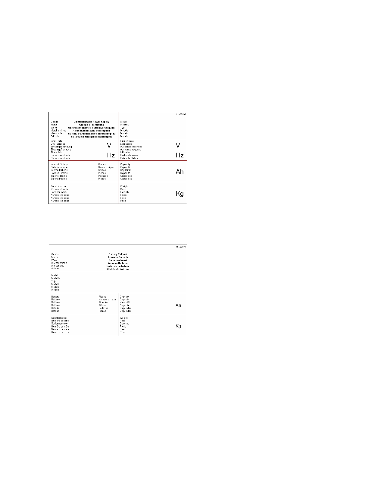
1 IDENTIFYING PACKAGED U.P.S.
On receiving the goods you should verify the contents. On the front of the package you will find the sticker which
will allow you to identify the contents.
In the picture you can see the identity sticker which is placed on the packaging of the equipment:
1. Ups type
2. Specifies voltage and frequency input admittance
3. Specifies voltage and frequency output admittance
4. Specifies the number of batteries which may be
inside the machine
5. Specifies internal battery capacity
6. Specifies the serial number of the product
7. Specifies weight
In the picture you can see the identity sticker placed on the packaging of the battery:
1. Specifies the battery cabinet model
2. Specifies the number of batteries contained
3. Specifies battery capacity
4. Specifies the serial number of the product
5. Specifies weight
1.1 VERIFYING THE GOODS
After making sure that the goods are those required, please check that the equipment has not been damaged. In order
to do this you must verify the integrity of the p ackaging. After having removed the packaging check that the metal
panels have not been damaged during transport. If the goods are not compliant in any way please put them back in their
original packaging and send them back to the manufacturer.
Picture 1.1
Picture 1.2
1
2 3
4 5
1
3
5
7
2
4
6
________________________________________________________________________________
EVO STAR 60-800
9
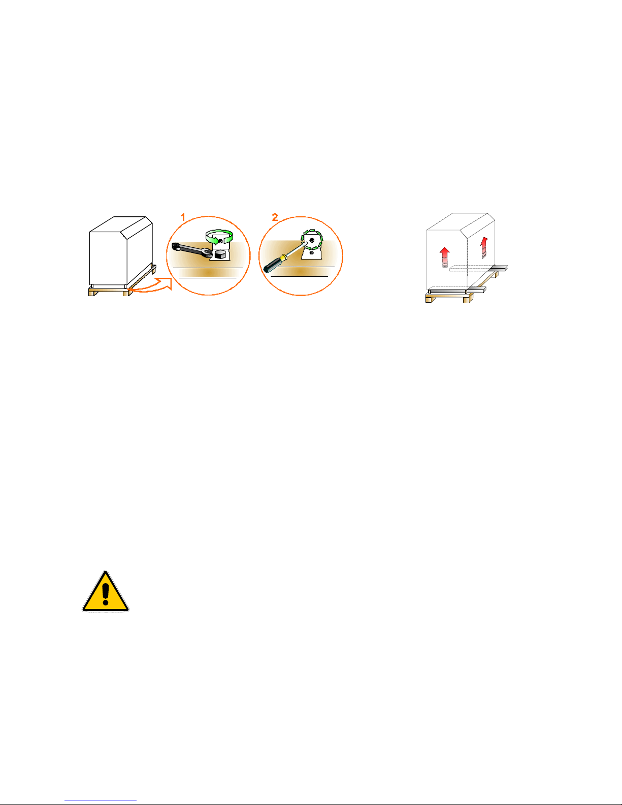
2 HANDLIND, STORING AND POSITIONING
2.1 HANDLING
1. Remove the screws which fasten the machine to the pallet (Picture 2.1)
2. Remove the wooden pallet by using a lift truck and carefully place it on the floor (Picture 2.2)
3. For floor handling you will only need a transpallet with a suitable loading capacity
2.2 U.P.S. STORAGE
2.2.1 U.P.S.
If you need to store the UPS this must be protected from dust and dirt (even if it is well packaged). It must not be
exposed to the inclemency of the weather and the room shouldn’t be too humid (humidity below 90% noncondensing), nor should the UPS be exposed to sources of heat; room temperature should be between +1 e +40°C.
2.2.2 BATTERY CABINETS
If you need to store a complete battery cabinet, you should respect all the conditions mentioned in the previous
paragraph. You should also remember that battery discharge over time, even when not in use, therefore it is necessary
to recharge them every 4 months.
In any case, you must follow the manufacturers’ indications to store the batteries.
Non-compliance with these indications can cause an efficiency decrease and a
shorter life of the storage batteries.
Picture2.1
Picture 2.2
________________________________________________________________________________
EVO STAR 60-800
10
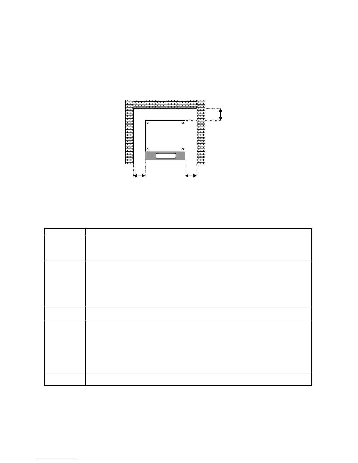
2.3 POSITIONING
Installation space varies according to the size of the U.P.S and to the battery cabinet. A distance margin from the
walls of the room where the U.P.S. is positioned is also necessary for air circulation and ordinary/extraordinary
maintenance. Please refer to picture 2.3 for minimum margin distances. All models need a distance margin of at least
40cm either side or at least a metre from the ceiling.
2.3.1 CHOOSING THE ROOM
Element Requirements
Room access
• All the doors which the equipment has to go through in order to reach the chosen room have to
be large enough to allow the passage of the U.P.S (c harts 8) and its handling equipment. We
advise you to forbid access to the place where the U.P.S. and its battery cabinets are placed to
all non authorized users.
Room size
• Room space must be suitable to allow installation of the equipment and periodical and
extraordinary maintenance.
• When choosing the rooms please remember that the equipment must not be exposed to the
inclemency of the weather, to corrosive substances, to excessive humidity (humidity below 90%
non-condensing) or to very high sources of heat.
• The environment should not be very dusty. Please be very careful if you decide to carry out any
building work after setting up the machine.
Floor load
• According to the data in charts 8 you must check that the floors of the chosen rooms can support
the equipment’s weight.
Ventilation
• Room temperature should be preferably between 15° and 25°C
• Ventilators expel the heat dissipated by the U.P.S. into the air, therefore the room structure must
be suitable to guarantee sufficient aeration to eliminate the heat produced by the U.P.S.
• If room temperature does not comply with the recommended parameters or if air circulation in
the room is not adequate, you must supply the room with a ventilation system or, if this should
not be sufficient, install an air conditioning system.
Safety rules
• The rooms where the U.P.S. is installed must be equipped according to fire and safety
regulations.
Picture 2.3
40 cm
40 cm 40 cm
U.P.S. from 60 to 800 KVA
________________________________________________________________________________
EVO STAR 60-800
11
3 GENERAL DESCRIPTION
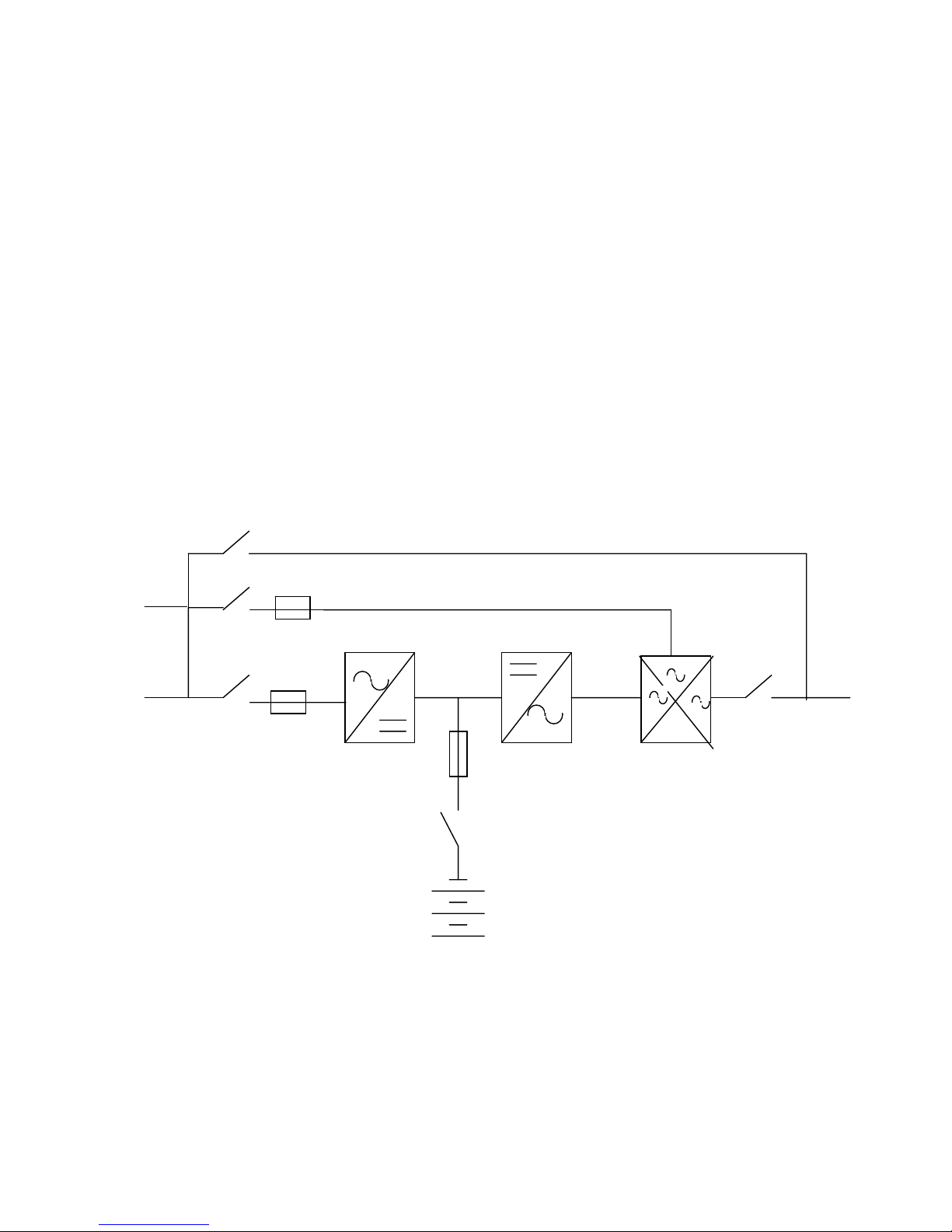
3.1 OPERATING PRINCIPAL
The U.P.S. is a continuous double conversion system with an output transformer. It works by carrying out a
continuous double conversion of the main supply, guaranteeing a constant stabilized supply of both voltage and
frequency, maintaining charge and control of the batteries (On-line functioning). In order to guarantee continuous
supply when the voltage of the electric system are no longer correct, power is drawn from the batteries. The system is
supplied complete with an automatic static commutator that connects the output to the back-up power supply, or if there
are special alarms such as the E.P.O. (Emergency Power Off) it shuts down completely output voltage.
3.2 DESCRIPTION AND PARTS
During normal functioning (figura 3.1) the system takes power from the mains by means of the input terminal (1).
The voltage goes through the disconnecting switch (4) and the fuse board (6/a ) in order to reach the rectifier module
(7), exiting which is a continuous controlled voltage available to charge or maintain battery efficiency (cross fuse (6/b)
and battery switch (8)) and to the inverter input (10). This step is to generate a three-phase voltage, stabilized and
synchronized with the back-up voltage. The static commutator (11) selects the power source to power the load, usually
on inverter (10). If there is an increase of output current or with specific alarms, the device (11) will commutate to the
emergency supply maintaining output continuity. If transferring takes place, output continuity is allowed by the
synchronism of the voltages generated with the emergency voltage. If asynchronous commutation should take place
there will be a power “dip” for maximum 20 ms.
When the power supply is not in the set parameters, the equipment maintains output voltage by taking power fro m
the batteries (9). The system is provided with a current control that keeps the current inside set parameters in the event
of current overloaded.
4
3
2
5
6/a
7
6/b
1
10
8
9
11
12
13
Back-up line
By-pass Line
1. Power supply
2. Manual By-pass
3. Back-up line switch
4. Mains switch
5. Back-up fuses board
6. Fuses board
a) Mains b)Battery
7. Rectifier
8. Battery switch
9. Inverter
10. Static switch
11. Output switch
12. Output
Picture 3.1
1/A
RECT.
INV.
M.B.
I.B.
BATT.
________________________________________________________________________________
EVO STAR 60-800
12
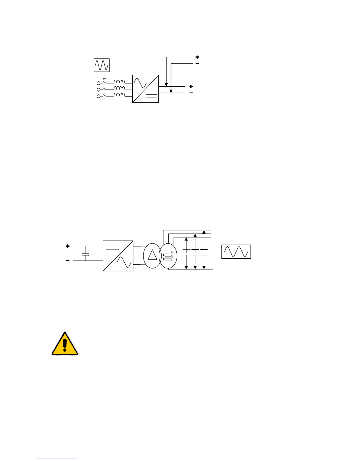
3.1.1 RECTIFIER
Rectifier indicated in picture with the abbreviation RECT, transforms alternating current voltage from main line to
direct current voltage. Its engineering allows, through a six pulse absorption to feed the inverter in its status of
maximum voltage output at the same time as the battery charge. Normally, direct current voltage is constantly set at
436Vdc (sustaining voltage), but when recharging the batteries, this voltage will be automatically limited b y a current
limiter.
In the following description the link from rectifier to inverter is defined as “Dc-link” and the voltage between its
poles is defined as “Dc link voltage”
3.1.2 INVERTER
The inverter, indicated in picture 3.1 with the abbreviation INV, has the role of transforming direct current voltage,
taken from the rectifier output, into sinusoidal voltage, which may be used by the user; This process is carried out by
using power semiconductors, piloted by a PWM signal, which through a transformer and a capacitance filter give us a
very stable three-phase voltage with a harmonic distortion lower than one unit.
The controlling logic of the inverter also controls output current intensity limiting it to a value which corresponds to
150% nominal current voltage.
3.1.2 STATIC COMMUTATOR
The static commutator indicated in picture 5 as B.S., is a commutator made with semiconductors which can select
which power source to connect appliances to. During normal functioning the U.P.S. output is taken at the inverter
output (U.P.S. on-line), but if there is an internal or external event it will commute to the reserve system.
Commutating from one source to another occurs without creating voltage
“dips” only with conditions of synchronism between inverter output and the
reserve system. If there is forced commuting, without synchronism, decided by
the user, this will occur with a voltage dip of max. 20 Sm.
Commuting Conditions on inverter:
1. Inverter switched on and working and synchronized with the
reserve system
2. Loss of system
3. Voluntary forcing through control panel
Commuting Conditions on reserve:
1. Malfunctioning of the inverter
2. Current overcharge
3. U.P.S. switched off
4. Voluntary forcing through control panel
Output voltage
L1 L2 L3
LN
Picture 3.3
Input voltage
To battery
To inverter
U
V
W
Picture 3.2
________________________________________________________________________________
EVO STAR 60-800
13
5. By-manual closing of the breaker
3.1.4 MANUAL BY-PASS
Il by-pass manuale, indicated in picture 3.1 as M.B., consists in a breaker which powers the critical load directly
from the main system. This device is particularly useful during ordinary/extraordinary maintenance, as it allows the
operator to deal with the internal circuits with a minimum risk of contact with voltaged elements.
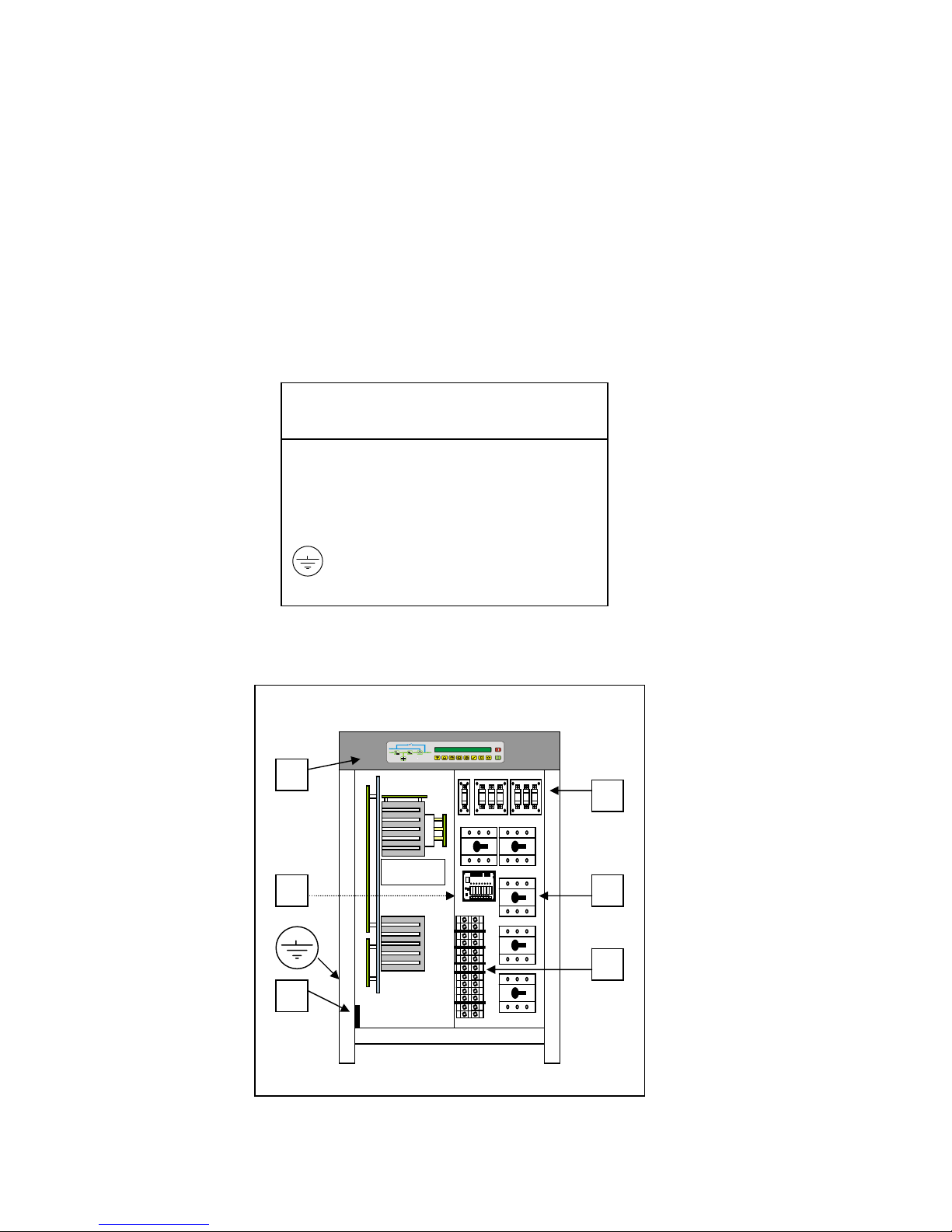
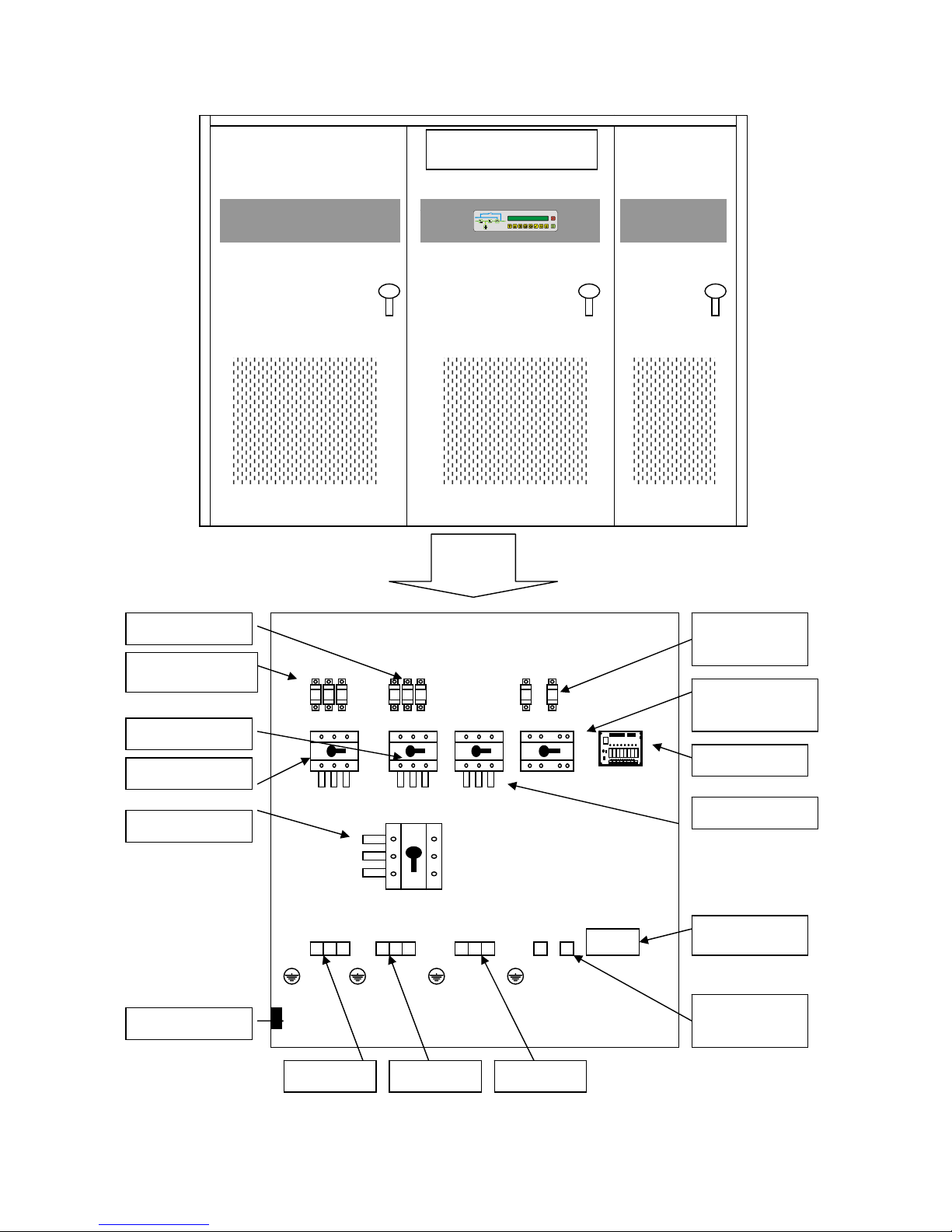
3.1.5 PART LAYOUT
It is important to be familiar with the parts that are necessary during the connection procedures before connecting
the equipment. In order to access the parts which will be described you must remove the “second access”, which is the
metal panel used to protect the inside parts of the U.P.S. and also to protect the user from accidental contacts with live
parts.
A = Display board
B = Relay board
C = Interface connector
D = Terminal
E = Breakers
F = Fuse cards
= Earthing
KEY
U.P.S. from 60 to 100 KVA
A
C
F
D
E B
Picture 3.4
________________________________________________________________________________
EVO STAR 60-800
14
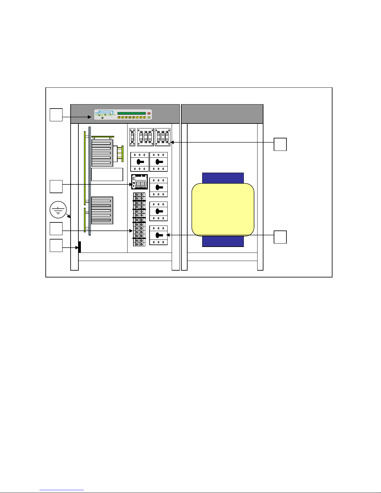
U.P.S. from 120 to 150 KVA
A
B
C
D
E
F
Picture 3.5
________________________________________________________________________________
EVO STAR 60-800
15
Battery
connection
Mains switch
Reserve switch
Output switch
Battery fuses
Battery switch
Spare fuses
Neutral bar
Rectifier fuses
Relay board
RS 232
By-pass switch
Reserve Input Output
Picture 3.6
U.P.S from 200 to 800
________________________________________________________________________________
EVO STAR 60-800
16
3.1.6 BREAKERS
The U.P.S. has a system of breakers, which allows the user to carry out the necessary operations in order to use and
carry out maintenance on the equipment and to shut down the power supply if there is an emergency. A sticker placed
on the second access specifies the name of each switch near the switch itself. The by-pass switch contains a protection
device so, as it cannot be disconnected inadvertently. The user can remove this protection device if he/she decides to
carry out a manual by-pass.
1. MAINS SWITCH Break the mains supply, as specified in point 1 picture 3.1
2. RESERVE SWITCH Break the secondary power supply, as specified in point 7 picture 3.1
3. MANUAL BY-PASS Short-circuits the secondary input with the output
4. OUTPUT SWITCH Break the loading power supply.
5. BATTERY SWITCH Break, according to the model, one or both battery polarities.
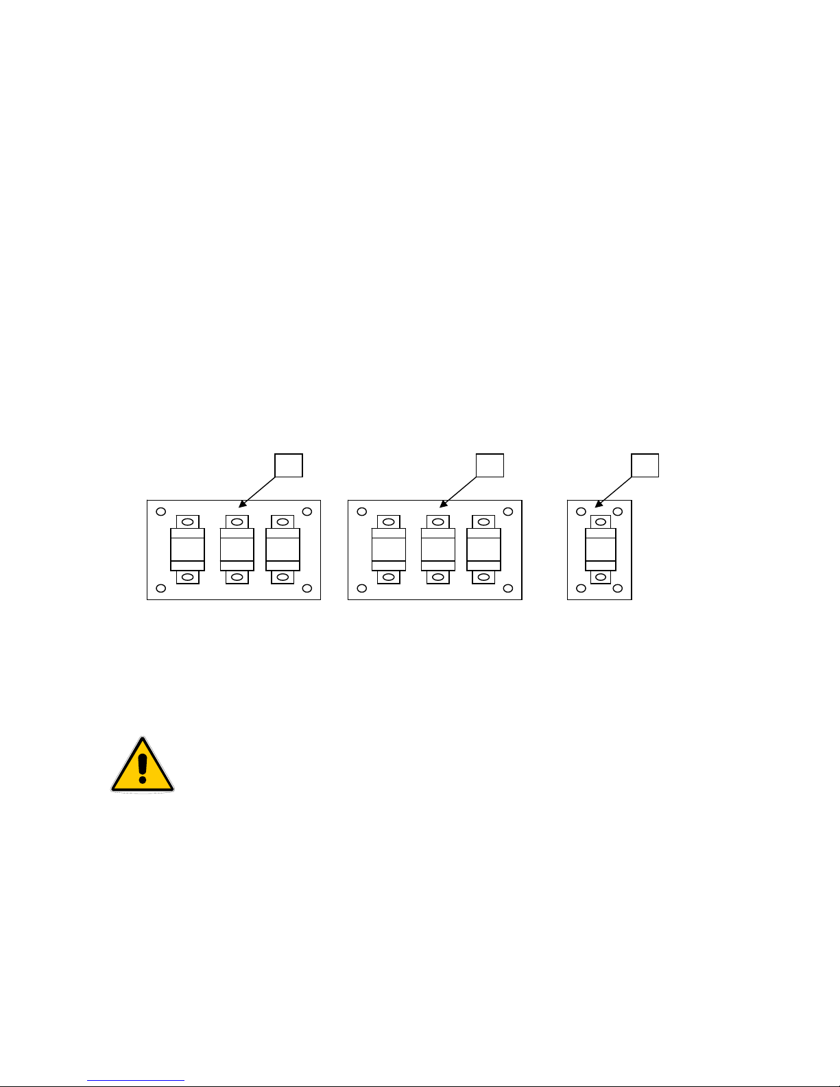
3.1.7 FUSES
The U.P.S. includes a system with two fuse groups, both counting three fuses each which are able to disconnect
electrical power input (points 1 and 7 picture 3.1), when the electrical power is not within the set parameters. The type
of fuse, which is used, guarantee quick intervention and therefore are a guarantee also for optimum protection of the
internal devices. Furthermore, there is also a fuse on the line, which connects the U.P.S. to the batteries (point 6 picture
3.1), both for internal and external batteries.
Board A, (picture 12), to the user’s left, protects the state of the rectifier input, board B , to the user’s right, protects
the reserve line. Whereas the single-fuse board C protects the battery line. In UPS over 150 KVA fuses are on
connection bars without board, for battery there are two fuses.
REPLACING THE FUSES
CAUTION! : ALL CONNECTING PROCEDURES DESCRIBED IN THIS CHAPTER
MUST BE CARRIED OUT BY AUTHORIZED ELECTRICIANS OR BY QUALIFIED
TECHNICIANS.
CAUTION! : BEFORE REPLACING THE FUSES YOU MUST CARRY OUT THE
MANUAL BY-PASS PROCEDURE WITH THE U.P.S. DISCONNECTED (CHAPTER 5)
A nut screw fastens each fuse. When replacing a fuse you must unscrew the two knurled nuts corresponding to the
fuse, which must be replaced, remove the washers, replace the fuse and put back the washers and the knurled nut in this
order. IMPORTANT spare fuses are supplied together with the U.P.S. If they have to be purchased please make sure
that they are extra-fast fuses for the current same as on machine so as to guarantee total protection.
A B C
Picture 3.7
________________________________________________________________________________
EVO STAR 60-800
17
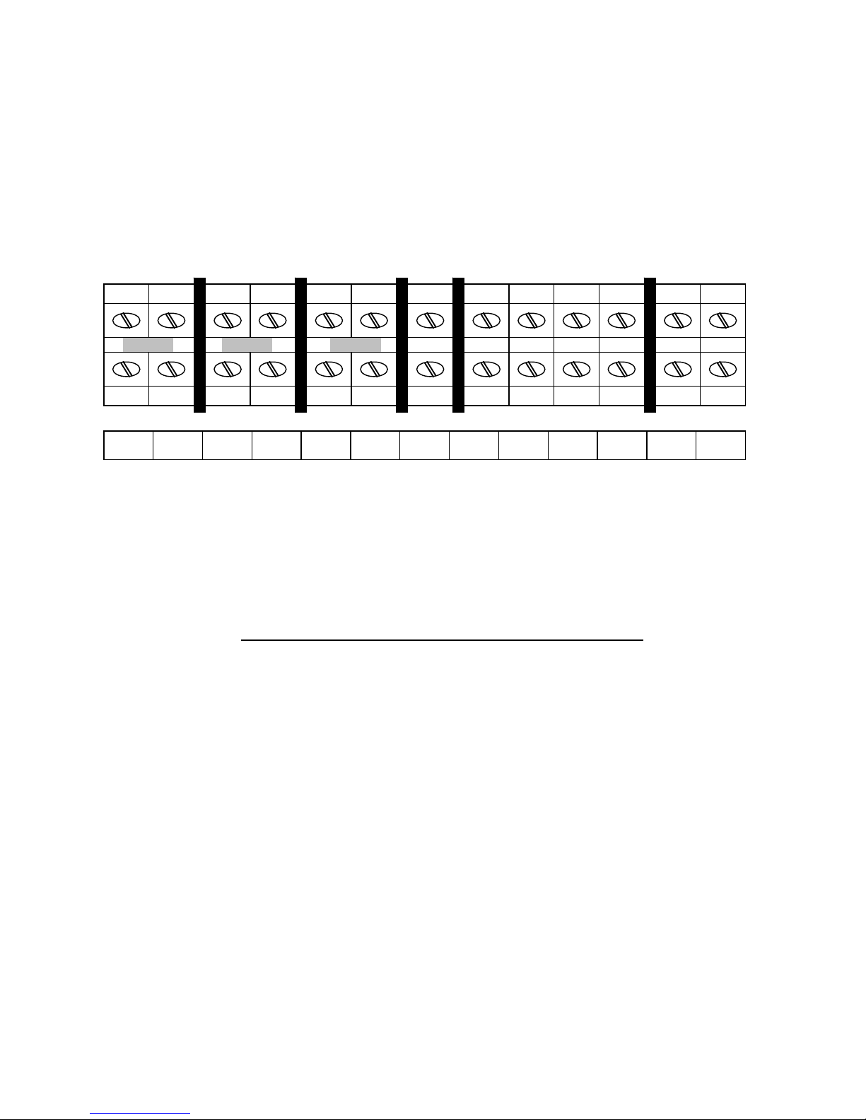
3.1.8 TERMINAL CONNECTORS
POWER UP TO 150 KVA
In all the models the terminal board is on the front of the U.P.S. protected by the second access.
It can be perpendicular or horizontal according to the model.
In any case, please refer to the alphanumeric specifications on the terminal board. The jumpers are arranged as in the
picture (highlighted in grey), and are used to short-circuit the main input and the reserve input. According to the type of
installation, you can remove them to connect the system to an auxiliary power source (back-up supply, generator).
U, V, W = Main input
U1, V1, W1, N1 = Reserve input
U2, V2, W2, N2 = Output
D(-),C(+) = Battery pole input. D(-) negative pole, C(+) positive pole.
In 100KVA device terminal D and C are double, in 120-150KVA also N1 and N2 are double
In this manual fase name U, V, W or R, S, T, or R, Y, B are equivalent.
POWER OVER 150 KVA
In the high power systems instead of using terminal boards for power connections a group of copper bars with
perforated ends are used. Therefore with the help of cable terminals, knurled screws and nuts a suitable connection for
the current values in circulation. As for the connection references please refer to the alphanumeric specifications on the
copper bars which respect the same specifications present on the terminal boards in equipment up to 200KVA.
U U1 V V1 W W1 N1 U2 V2 W2 N2 D(-) C(+)
Picture 3.8
 Loading...