

Page 1
1
Uninterruptible Power Systems
EVO DSP TT
10-100kVA
User’s manual
Page 2
2
Important Notice
Thank you for purchasing TECNOWARE UPS.
This document provides instructions about safety, installation and handling of the UPS. It is necessary to
read the manual completely before working on this equipment.
Read the manual completely before working on this equipment!
Keep this manual near UPS for easy consultation!
Symbols
This symbol points out the instructions which are especially important.
This symbol points out the risk of electric shock if the following instruction is not obeyed.
This symbol points out the instructions, which may result in injury to the operator or damage to
the equipment if not obeyed.
Copyright 2009 TECNOWARE s.r.l. All rights reserved.
All trademark are property of their respective owners.
TECNOWARE s.r.l.
www.service.tecnoware.com
This manual has been printed and edited by TECNOWARE s.r.l.
Manual Version 1.0 – May 2009 – Initial Issue
Page 3

3
Index
1 Safety ...................................................................................................................................................... 5
2 Installation ............................................................................................................................................. 6
2nd1 Transportation ................................................................................................................................................................... 6
2nd2 Unpacking........................................................................................................................................................................... 6
2nd3 Storage ................................................................................................................................................................................. 6
2nd4 Location and Connection of the UPS ........................................................ Errore. Il segnalibro non è definito.
2nd4.1 Environmental Requisites ....................................................................................................................................... 6
2nd4.2 Electrical Requisites .................................................................................................................................................. 7
2nd5 Connections ....................................................................................................................................................................... 8
2nd5.1 Power Connections .................................................................................................................................................. 8
2nd5.1.1 Protective Earth (Ground) Connections ............................................................................................................... 10
2nd5.1.2 Input Connection ....................................................................................................................................................... 10
2nd5.1.3 Separated by-pass mains input connection (optional) ........................................................................................ 11
2nd5.1.4 External Battery Connection .................................................................................................................................... 11
2nd5.1.5 Output Connection .................................................................................................................................................... 11
2nd5.2 Communication Interface Connections.............................................................................................................. 11
3 Modes of Operation .............................................................................................................................. 12
3rd1 Bypass Mode .................................................................................................................................................................... 13
3rd2 Normal Mode .................................................................................................................................................................. 14
3rd3 Battery Mode .................................................................................................................................................................... 14
4 Control and Monitoring ........................................................................................................................ 15
4th1 Front Panel ....................................................................................................................................................................... 15
4th1.1 Keypad ...................................................................................................................................................................... 15
4th1.2 Mimic Panel ............................................................................................................................................................. 16
4th1.3 Liquid Crystal Display (LCD) and User Menu .................................................................................................. 17
4th1.4 Buzzer ....................................................................................................................................................................... 20
5 Operating Procedures ........................................................................................................................... 21
5th1 Commissioning ................................................................................................................................................................ 21
5th2 Decommissioning ........................................................................................................................................................... 21
5th3 Switching into manual by-pass during operation ...................................................................................................... 22
5th4 Returning from manual bypass to UPS ....................................................................................................................... 22
5th5 Connection to a generator ............................................................................................................................................. 22
6 Operating Procedures for Parallel Systems .......................................................................................... 23
6th1 Introduction ..................................................................................................................................................................... 23
6th2 Procedure for Commissioning and Start Up ( First Installation ) ........................................................................ 23
6th3 Procedure for Transferring to Static Bypass .............................................................................................................. 26
6th4 Procedure for Transferring to ( Maintenance ) Manual Bypass .............................................................................. 26
6th5 Procedure for Switching OFF ...................................................................................................................................... 26
7 Features and operating limits .............................................................................................................. 27
7th1 Mains limits for normal operation ............................................................................................................................... 27
7th2 By-pass mains limits for bypass operation.................................................................................................................. 27
7th3 Battery test ........................................................................................................................................................................ 27
7th4 Overload behavior .......................................................................................................................................................... 28
7th5 Electronic short circuit protection ............................................................................................................................... 28
8 Communication ................................................................................................................................... 29
8th1 RS232 Communication .................................................................................................................................................. 29
Page 4

4
8th2 RS422 Communication .................................................................................................................................................. 29
8th3 Digital Inputs (UPS OFF and GEN ON) .................................................................................................................. 30
8th4 Free Contact Communication ...................................................................................................................................... 30
9 Maintenance .......................................................................................................................................... 31
9th1 Battery fuses ..................................................................................................................................................................... 31
9th2 Batteries ............................................................................................................................................................................ 31
9th3 Fans ................................................................................................................................................................................... 31
9th4 Capacitors ......................................................................................................................................................................... 31
10 Troubleshooting ................................................................................................................................... 32
11 Technical Specifications ...................................................................................................................... 35
12 Internal Battery Location & Connection Instructions ......................................................................... 37
13 Internal Battery Location & Connection Diagram .............................................................................. 38
Page 5
5
1 Safety
Information related to the safety of the UPS, loads and the user is summarized below.
But the equipment should not be installed before reading this manual completely.
The equipment may only be installed and commissioned by authorized technical persons.
When the UPS is brought from a cold place to a warmer place, humidity in the air may cause
condensation in the UPS. In this case, allow UPS to stand for two hours in the warmer place
before beginning with the installation.
Even if no connection has been done, hazardous voltages may exist on connection terminals and
inside the UPS. Do not touch these parts.
Connect the PE (Earth) ground connector before connecting any other cable.
Do not put the battery fuses into the fuse holder before operating the equipment and seeing the
“NORMAL” message on the LCD.
The connections shall be made with cables of appropriate cross-section in order to prevent the
risk of fire. All cables shall be of insulated flexible type (tri-rated) and shall not be laid out on the
walk path of persons. Cables crossing a path must be protected in accordance with local
electrical and safety regulations.
Do not expose UPS to rain or liquids in general. Do not put any solid objects into any access
/vent hole or space .
The equipment shall be operated in an environment, which is specified in “Location and
Connection of the UPS” section of this manual.
Affix a label bearing the following expression, on the distribution panels feeding the UPS :
“Isolate the Uninterruptible Power Supply before working on this circuit”
Do not plug the communication cables in or out during lightening or electrical storms.
The equipment shall only be maintained and fixed by authorized technical persons.
In case of a fault situation (damaged cabinet or connections, penetration of foreign materials into
the cabinet etc.) de-energize the UPS immediately and consult with Tecnoware Technical Service.
Used/dead batteries must be disposed of at an authorized waste disposal centre – local
regulations may apply – batteries must not be put in a land fill .
Keep this manual nearby the UPS for easy consultation.
The equipment shall be packed properly during transportation.
The equipment is compliant with the European Community directives. Hence it is marked:
Page 6
6
2 Installation
2.1 Transportation
The UPS must remain in a vertical position throughout the transportation.
Make sure that the floor can support the weight of the system – check with building engineer if not sure.
2.1 Unpacking
Equipment and batteries whose packaging is damaged during transportation shall be inspected by
a qualified technical person before starting with the installation.
The procedure is as follows:
Remove the bands and the protective packaging from the UPS.
Use suitable equipment to remove the UPS from the pallet.
Mount the cabinet parts supplied with the UPS after positioning and connecting the UPS.
The equipment shall be packed properly during transportation. Therefore it is recommended to
keep the original package for future needs (eg. Further transportation or return to Service
Department).
Check if the following are provided with the equipment
Key of the cabinet door
Battery fuses (three pieces)
Test report
2.1 Storage
Recommended storage temperature, humidity and altitude values are listed in the “Technical
Specifications” section.
If the batteries will be stored for longer than 2 months, they must be charged periodically. Charge period
depends on the storage temperature. The relationship is as shown below:
Every 9 months if the temperature is below 20 °C,
Every 6 months if the temperature is between 20 °C and 30 °C,
Every 3 months if the temperature is between 30 °C and 40 °C,
Every 2 months if the temperature is over 40 °C
2.1 Location and Connection of the UPS
2.1.1 Environmental Requisites
This product meets the safety requirements for devices to be operated in restricted access locations
according to EN 60950-1 safety standard, which states that the owner should guarantee the following:
Access to the equipment can only be gained by service persons or by users who have been
instructed about the reasons for the restrictions applied to the location and about any precautions
that shall be taken and,
Page 7

7
Access is through the use of a tool or lock and key, or other means of security and is controlled
by the authorised person responsible for the location.
Recommended operating temperature, humidity and altitude values are listed on the “Technical
Specifications” section. Air conditioning may be required to provide these values.
Other requisites are:
The equipment and the batteries shall not be exposed to direct sunlight or placed near to a heat
source.
Do not expose UPS to rain or any liquids in general. Do not introduce any solid objects.
Avoid dusty environments or areas where dust of conductive or corrosive materials is present.
Air outlets of the UPS are on sides, front and back. Leave at least 75 cm at the front and both
sides and 50 cm at the back for maintenance and ventilation.
2.1.1 Electrical Requisites
The installation must comply with local national installation regulations.
The electrical distribution panels for the mains and separate by-pass mains inputs must have a protection
and disconnection system. Disconnection devices used in these panels shall disconnect all line conductors
and the neutral conductor simultaneously. The following table shows the recommended size of the mains
and separate by-pass mains input protection devices (thermal, magnetic and differential) and the cable
cross-sections for the linear loads.
UPS
Input
thermal
protection
Bypass
mains input
thermal
protection
Input cable
cross-
section
Bypass
mains input
cable
cross-
section
Battery
cable cross-
section
Neutral
Cable
Cross
section
Leakage
current
protection*
10 kVA
25 A 25 A 6 mm2
6 mm2
6 mm2
10 mm
2
30 mA
15 kVA
25 A 25 A 6 mm2
6 mm2
6 mm2
10 mm
2
30 mA
20 kVA
40 A 40 A 10 mm
2
10 mm
2
10 mm
2
16 mm
2
30 mA
30 kVA
63 A 63 A 16 mm
2
16 mm
2
16 mm
2
25 mm
2
30 mA
40 kVA
80 A 80 A 16 mm
2
16 mm
2
16 mm
2
25 mm
2
30 mA
60 kVA
100 A
100 A
25 mm
2
25 mm
2
25 mm
2
35 mm
2
30 mA
80 kVA
125 A
125 A
35 mm
2
35 mm
2
35 mm
2
50 mm
2
30 mA
100 kVA
160 A
160 A
35 mm
2
35 mm
2
35 mm
2
50 mm
2
30 mA
Input magnetic protection devices shall have D characteristic.
*Load leakage currents are added to those generated by the UPS. If loads with high leakage currents are
present, adjust this value accordingly. It is recommended to adjust the protective device after measuring
the total leakage current with the UPS installed and operational with the intended load.
During transitory phases (power failure, return and voltage fluctuations) short leakage current peaks may
occur. Make sure that the protection is not activated in such cases.
If the loads have a nonlinear characteristic, the current on the mains input, separate by-pass
mains input and output neutral conductors may have a value that is 1.5-2 times the phase value
during operation. In this case, size the neutral cables and the input/output protection accordingly.
Page 8
8
According to EN 62040-1-2, the user shall place a warning label on the input distribution panel
and the other primary power isolators, in order to prevent the risk of electric shock caused by a
fault voltage on the UPS. The label shall carry the following wording:
Isolate uninterruptible power supply (UPS) before working on this circuit
2.1 Connections
Connections shall be done by authorized technical staff only.
When the UPS is brought from a cold place to a warmer place, humidity of the air may
condensate in it. In this case, wait for two hours before beginning with the installation.
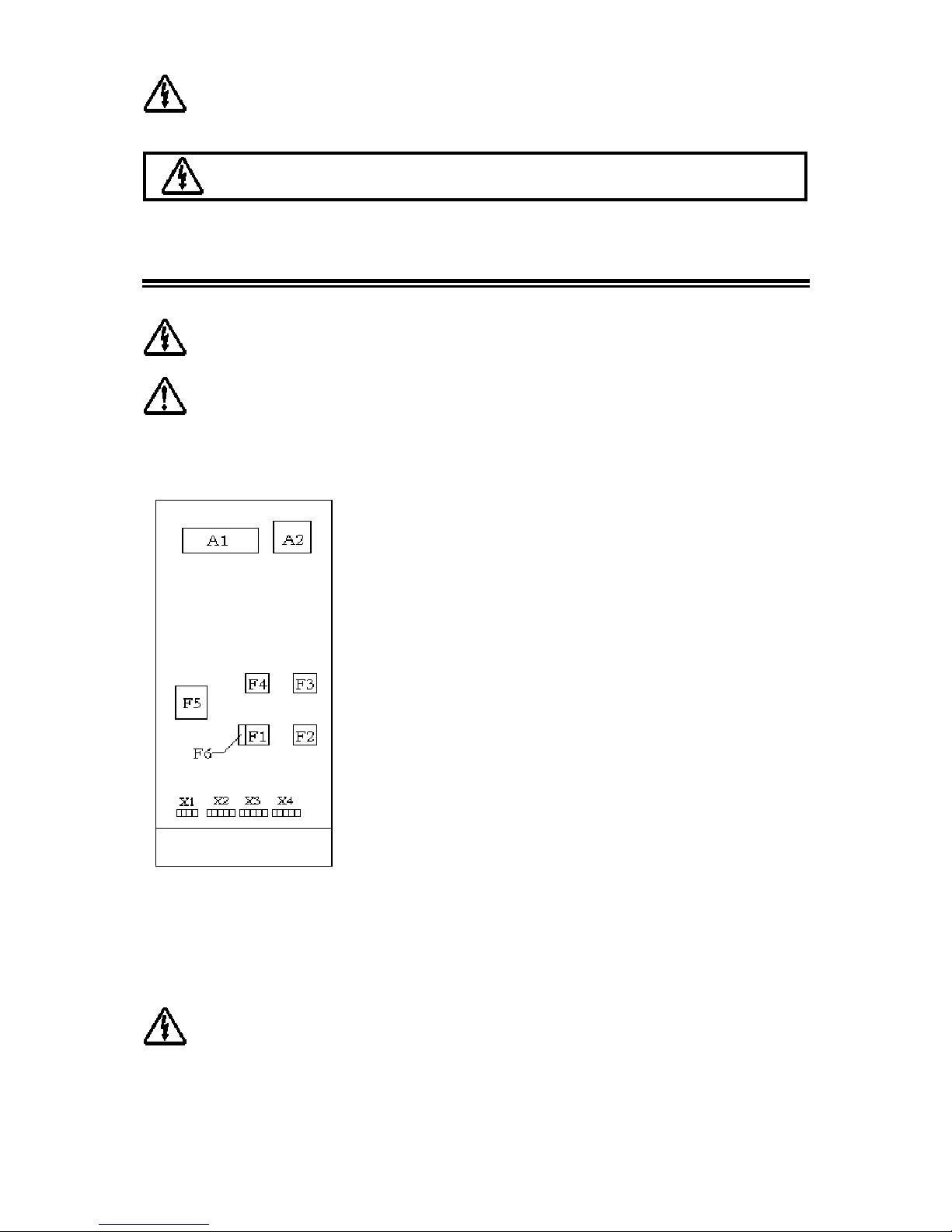
Layout of the connection terminals and boards are shown below:
A1: Communication interface board
A2: Parallel connection board (optional)
F1: Input circuit breaker
F2: Output circuit breaker
F3: Manual by-pass circuit breaker
F4: By-pass circuit breaker (optional)
F5: Battery circuit breaker
F6: Inrush fuse
X1: Battery terminals
X2: Input mains terminals
X3: Separate by-pass mains terminals (optional)
X4: Output terminals
2.1.1 Power Connections
Devices with internal batteries may have dangerous voltages on the battery terminals
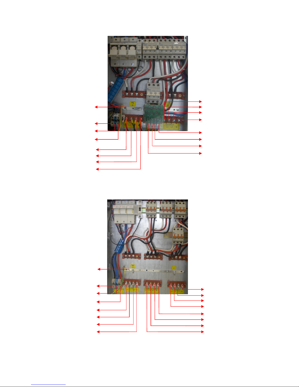
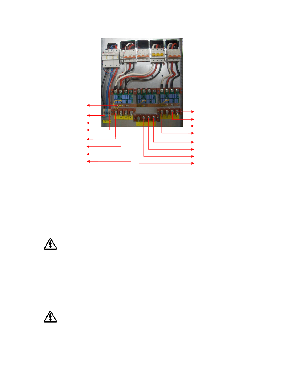
The power screw terminals are located on the lower front side of the UPS. Refer to the names of each
terminal to identify it during connection
Page 9
9
10-15-20-30kVA UPS Terminal Connections
40-60kVA UPS Terminal Connections
* If Split/separated bypass is not used – link input to these terminals (connections are
then common). Ensure cables are same for each connection (L1 input & L1 bypass etc)
BATTERY (-)
BATTERY
NEUTRAL
BATTERY
(+)
PE
INPUT
L1
INPUT
L2
INPUT
L3
INPU
T
NEUTRAL
OUTPUT
L1
OUTPUT
L2
OUTPUT
L3
OUTPUT NEUTRAL
SPLIT
-
BYPASS NEUTRAL
SPLIT BYPASS L3
SPLIT BYPASS
L2
SPLIT BYPASS L1 (*)
PE
BATTERY (
-)
BATTERY
NEUTRAL
BATTERY
(+)
INPUT
L1
INPUT
L2
INPUT
L3
INPUT NEUTRAL
SPLIT BYPASS NEUTRAL
SPLIT BYPASS L3
SPLIT BYPASS L2
SPLIT BYPASS L1
OUTPUT NEUTRAL
OUTPUT L3
OUTPUT L2
OUTPUT
L1
Page 10
10
80-100kVA UPS Terminal Connections
Cables shall be passed through the hole under the connection terminals.
Make sure that all circuit breakers are “OFF”/”0” before starting with the installation.
Connections shall be done in the order below only.
2.1.1.1 Protective Earth (Ground) Connections
The device shall be earthed for a safe and reliable operation. Connect the PE ground connectors
before connecting any other cable
Input protective earth connection terminal (PE) of the UPS shall be connected to ground with a low
impedance connection.
PE terminals of the loads shall be connected to output protective earth terminal of the UPS.
If there is an external battery cabinet present, it shall be grounded via battery protective earth terminal of
the UPS. Battery case must be earthed only – do not connect any DC/ battery point to PE earth.
2.1.1.1 Input Connection
Bring the circuit breaker on the distribution panel to “OFF” or “0” position before making the
connections
Connect the phases to input (X2) L1, L2 and L3 terminals.
PE
BATTERY (
-)
BATTERY NEUTRAL
BATTERY
(+)
INPUT
L1
INPUT NEUTRAL
INPUT
L2
INPUT
L3
OUTPUT NEUTRAL
OUTPUT L3
SPLIT BYPASS NEUTRAL
SPLIT BYPASS L3
OUTPUT L2
OUTPUT
L1
SPLIT BYPASS L2
SPLIT BYPASS L1
Page 11
11
A definite phase sequence is needed for the UPS to operate. If you encounter “IN SEQ FLR” alarm at
start up, stop and switch off the UPS, ensure the protection devices (breakers/isolators) on the input
distribution panels are “0”/”OFF” and then interchange any two phases on the UPS input only.
Connect neutral to N terminal of X2.
2.1.1.1
Separated by-pass mains input connection (optional)
Bring the circuit breaker on the distribution panel to “OFF” or “0” position before making the
connections
Connect the phases to bypass (X3) L1, L2 and L3 terminals.
Make sure that the phases have the same sequence with the input supply.
Connect neutral to N terminal of X3.
2.1.1.1
External Battery Connection
Do not put the battery fuses into the fuse holder (F5) before operating the equipment and seeing
the “NORMAL” message on the LCD.
Devices with internal batteries may have dangerous voltages on the battery terminals
To connect external batteries, do the following:
Switch the circuit breaker of the external batteries to “OFF” or “0” position.
Connect the (-) pole of the external batteries to the battery (-) terminal,
Connect the (+) pole of the external batteries to the battery (+) terminal,
Connect the midpoint of the external batteries to the battery N terminal.
Danger of explosion and fire if batteries of the wrong type are used.
2.1.1.1
Output Connection
To enable the short circuit protection feature of the UPS, each load shall be fed over a separate
circuit breaker chosen according to the load current. This may provide quick disconnection of the
short circuited load and operation continuity of the other loads. To obtain maximum protection,
the rating of each individual load circuit breaker shall have the minimum value, which is enough
to carry the full load current continuously.
Rated apparent and active power of the loads shall be less than the UPS power ratings.
Connect the loads to output (X4) Line and N terminals.
2.1.1 Communication Interface Connections
Related information is given in “communication” section.
Page 12
12
3 Modes of Operation
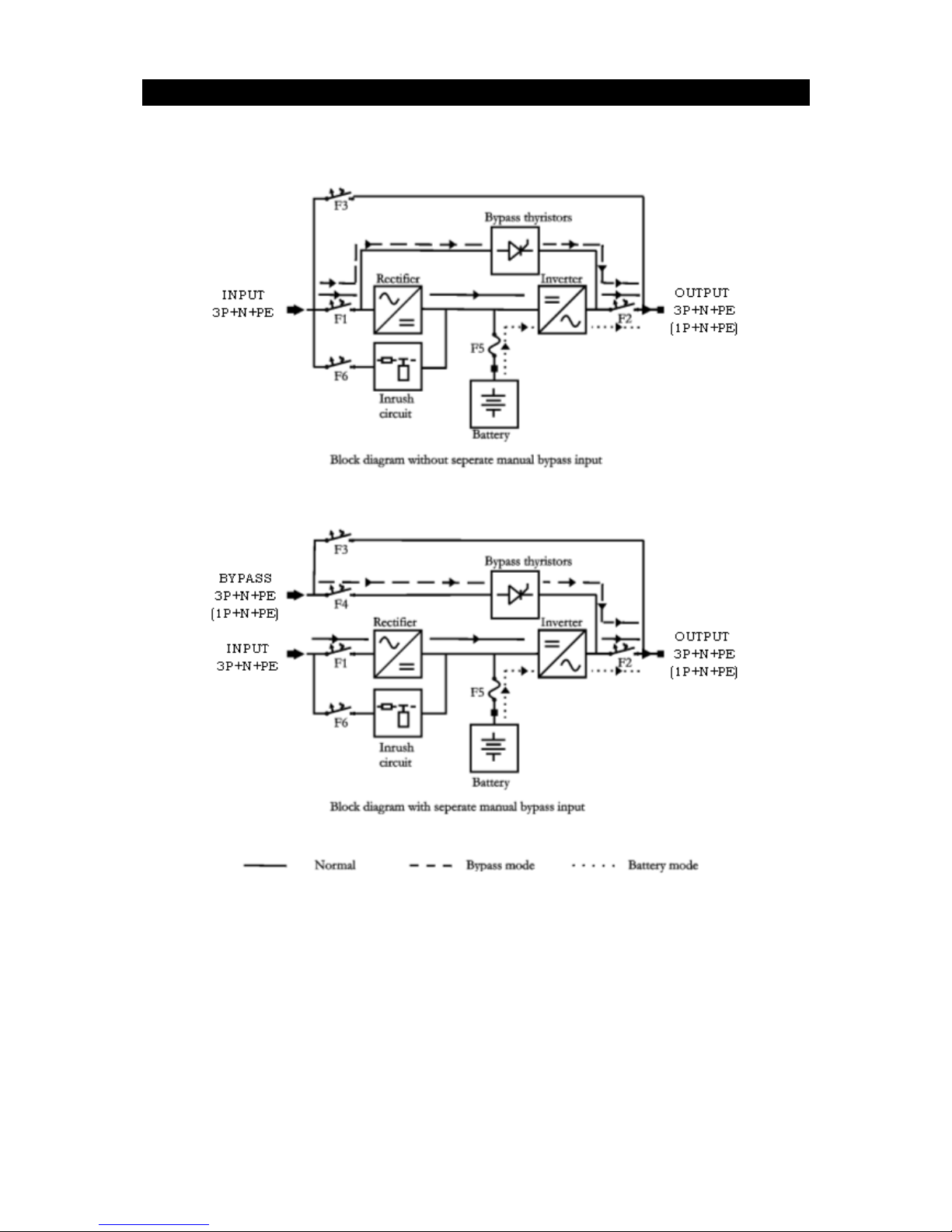
There are three operation modes, which differ in the path of the energy flow.
UPS block diagrams and the energy flow path in each operation mode is shown below:
When UPS has no separate bypass mains input, bypass line is also fed from the mains input. Thus, if such
a device is in question, mains input shall be comprehended when the bypass mains input is referred in the
following sections of the manual.
UPS behavior at the start-up is different from the usual operation. The UPS can only operate in bypass
mode during start-up. So, in order for the UPS to start-up, frequency/waveform/rms value of the bypass
mains voltage shall be in acceptable limits and bypass shall be enabled.
Page 13

13
After start-up, the following applies:
Operation mode depends on the priority, inverter, rectifier and bypass preferences made by the user and
mains, separate by-pass mains and battery voltages.
Priority and inverter, rectifier and bypass preferences can be set by using the COMMANDS and extra
commands (EXTCMNDS) menus.
If operation in any of these modes is impossible, output voltage will not be present. In this case, loads will
not be fed, and “VSECFLR” message is shown on the LCD instead of operation mode.
3.1 Bypass Mode
Devices without separate bypass mains input, energy is drawn from the mains. In devices with separate
bypass mains input, energy is drawn from the separate bypass mains.
Loads are fed via static bypass line.
Output voltage has the same amplitude, frequency and waveform as the input voltage.
Current drawn by the loads are only limited by the thermal/magnetic switches over the energy flow path.
Voltage, frequency and waveform of the bypass supply shall be within their tolerance limits, and bypass
shall be enabled for the UPS to operate in this mode.
When the upper provisions are met, the UPS works in bypass mode in the following conditions:
During the start-up
If the bypass priority is selected
If the inverter is disabled or blocked
In case of a prolonged overload
ECO Mode
You can save energy by selecting the bypass priority. Efficiency in bypass mode is higher than the
efficiency in normal mode. If the bypass priority is selected, the UPS will operate in bypass mode
whenever the frequency/waveform/rms value of bypass mains voltage is within their tolerance limits. If
the bypass voltage goes beyond these limits, the UPS switches into normal operation.
Bypass mode does not provide perfect stability in frequency/waveform/rms value of the output
voltage like in normal mode. Thus, the use of this mode should be carefully executed according to
the level of protection required by the application.
Bypass mode does not provide electronic short circuit protection like in normal mode. If a short
circuit occurs on the output during bypass operation, the thermal/magnetic protection will act
and all loads will be de energized – load will be stopped.
Prolonged overloads may cause the thermal/magnetic protection to act. In this case, all loads will
be de energized – load output will be stopped.
Page 14

14
3.1Normal Mode
Energy is drawn from the mains input.
Loads are fed via the rectifier and the inverter. The AC voltage at the input is converted to a DC voltage
by the rectifier. The inverter converts this DC voltage to an AC voltage with a stable sinusoidal waveform,
amplitude and frequency.
Output voltage is sinusoidal and has a regulated amplitude and frequency. It is independent from the input
voltage.
The inverter is synchronized in frequency with the bypass mains input to enable load transfer to the
bypass supply without any interruption, in case of an overload or inverter failure.
Voltage and frequency of the mains input shall be within their tolerance limits, and both the rectifier and
the inverter shall be enabled for the UPS to operate in this mode.
When the upper provisions are met, the UPS works in normal mode in the following conditions:
If the inverter priority is selected.
If the bypass priority is selected but bypass is disabled or frequency/waveform/rms value of
bypass mains voltage is not within acceptable limits.
3.1 Battery Mode
Energy is drawn from the batteries. Loads are fed via the inverter.
Output voltage is sinusoidal and has a regulated amplitude and frequency. It is independent from the
battery voltage.
Battery voltage shall be within acceptable limits and the inverter shall be enabled for the UPS to operate in
this mode.
When the upper provisions are met, the UPS works in battery mode in the following conditions:
If rectifier is disabled.
If the rectifier is disabled or frequency/waveform/rms value of mains voltage is not in acceptable
limits.
Page 15
15
4 Control and Monitoring
4.1 Front Panel
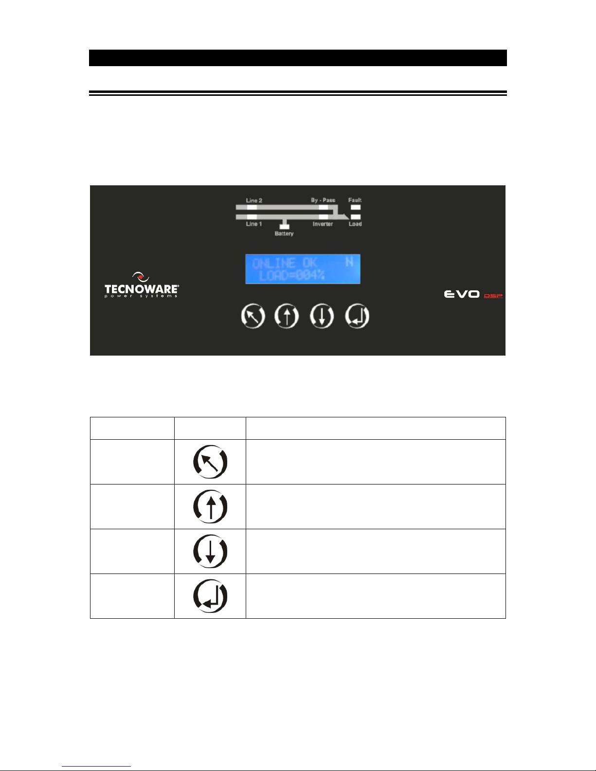
The front panel located on the upper part of the UPS informs the user about operating status, alarm
conditions and measurements. It also provides access to controls and configuration parameters.
Front panel shown below consists of three parts. As mimic panel provides basic information about the
energy flow path and existing alarms, LCD (liquid crystal display) offers detailed information and provides
access to controls. Keypad enables the user to move in the menu and to make selections.
4.1.1 Keypad
Functions of the buttons are given below:
BUTTON SYMBOL DEFINITION
ESC
Exit from the current menu
UP
Scrolls the available menus/values upwards. It increases the
value each time it is pushed when changing a parameter.
DOWN
Scrolls the available menus/values downwards. It decreases the
value each time it is pushed when changing a parameter.
ENTER
Enters the menu displayed on the screen. It makes selections or
confirms the choice/changes made.
Page 16

16
4.1.2 Mimic Panel
Mimic panel is a diagram, which shows the path of energy flow in the UPS by means of several LED’s.
Definitions of LED status are shown below:
LED's
ID COLOR DEFINITION STATE
Line 1 Green
Input mains voltage is OK and rectifier is active Steady
Input mains voltage is OK and rectifier is inactive
Flashing
Input mains voltage is very close to its upper/lower limit and rectifier is
active
Input mains voltage is not OK Off
Line 2 Green
Bypass voltage is OK Steady
Bypass voltage is not OK and output voltage is synchronized to the
bypass voltage
Flashing
Bypass mains voltage is not OK and output voltage is not synchronized
to the bypass voltage
Off
Battery Red
Battery mode is active and battery voltage is OK
Steady
UPS is performing battery test and battery voltage is OK
Battery mode is active and battery voltage is close to its lower limit
(energy available in the battery is about to be depleted)
Flashing
Battery test is active and battery voltage is close to its lower limit
(energy available in the battery is about to be depleted)
Rectifier is active and able to supply whole power required by the
inverter
Off
Inverter Green
Load is fed via inverter Steady
Inverter is not active Off
Load Green
Load is powered Steady
Load is powered but UPS is overloaded Flashing
Output voltage is not OK Off
Bypass Yellow
Load is fed via static bypass line Steady
Bypass is not active Off
Fault Red
No alarms Off
A minor alarm is present Flashing
A major alarm is present Steady
Page 17
17
4.1.3 Liquid Crystal Display (LCD) and User Menu
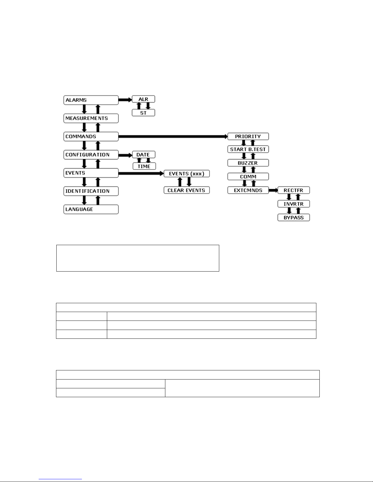
LCD provides detailed information about device status, alarms and measurements. It also enables the
operator to manage the UPS. All information, commands and configuration parameters are given in a
menu, which has the following structure:
LCD consists of two lines and has the following structure:
“OPERATING MODE” or “VSECFLR”
“MENU or PARAMETER NAME”
If there is no voltage on the output, VSECFLR message is displayed on the upper line.
Operation mode parameter is one of the notations below:
OPERATING MODE NOTATIONS
NORMAL Normal mode
BYPASS Bypass mode
BATT Battery mode
Menu and parameter descriptions are given below:
ALARMS MENU
ALR = “XXXXXXXXXXXX”
12 digit service codes.
Note these numbers before referring to technical service. ST = “XXXX-XXXXXXXX”
Alarm codes and names can be seen by entering the ALR submenu.
Page 18

18
CODE NAME DEFINITION
A01 BYP BADSHAPE
Bypass mains voltage is different than the inverter reference signal (e.g. its
frequency is beyond synchronization limits or it has a total harmonic
distortion > %10)
A02 BYP VOL HIGH Bypass mains voltage is higher than its upper limit
A03 BYP VOL LOW Bypass mains voltage is lower higher than its lower limit
A06 BYP SYN FAIL
Frequency of bypass mains voltage is beyond the frequency range for bypass
operation or bypass mains voltage is very low
A07 BYP SEQ FAIL Phase sequence of bypass mains voltages is not OK
A08 MNBYP SW ON Manual bypass switch is “ON”
A09 INV TMP HIGH Inverter block temperature is very high
A10 OUT OVERLOAD RMS current drawn from any of the output lines exceeds its nominal value
A11 BYP ACT Bypass is activated.
A12 INV NOT ACT Inverter is not started due to a fault
A13 INV BLCK Inverter operation is automatically stopped due to a fault
A14 VSEC NOT OK Output voltage is beyond its limits
A17 INP VOL HIGH Input line/neutral voltage is higher than its upper limit
A18 INP VOL LOW Input line/neutral voltage is lower than its lower limit
A21 INP SYN FAIL
Frequency of mains voltage is beyond the frequency range for normal
operation or mains voltage is very low
A22 INP SEQ FAIL Phase sequence of input mains voltages is not OK
A23 REC TMP HIGH Rectifier block temperature is very high
A24 REC OVERLOAD RMS current drawn from any of the input lines exceeds its nominal value
A25 VDC HIGH DC bus voltages is higher than its upper limit
A26 VDC LOW
DC bus voltages is lower than its lower limit
may mean that the battery is empty during battery operation
A27 REC NOT ACT Rectifier is not started due to a fault
A28 REC BLCK Rectifier operation is automatically stopped due to a fault
A30 TESTING BATT Battery test is being performed
A33 REC OFF Rectifier is inactive
A34 INV OFF Inverter is inactive
A35 BYP OFF Bypass is inactive
A36 BYP PRI HIGH Priority is Bypass
A37 BATT DISCHAR Batteries are discharging after a mains failure
A38 VDC NOT OK DC bus voltage is out of its normal range
A39 T-AMP HIGH Ambient temperature exceeds its upper limit
A40 GENSET ON Generator friendly operation is activated
A41 EMG STOP ON Emergency stop is activated
A42 MINOR ALR Minor Alarm
A43 MAJOR ALR Major Alarm
A44 BATT TS FAIL Batteries failed in the battery test
A45 BATT CR OPEN Battery Circuit Breaker is open
A47 INV RX T-OUT Communication between the inverter and the front panel is lost
A48 REC RX T-OUT Communication between the rectifier and the front panel is lost
All alarms except VSEC NOT OK are minor.
Page 19

19
MEASUREMENTS MENU
MEASUREMENT DEFINITION
LD = XXX,XXX,XXX % Ratio of the actual inverter active power of each line to its nominal
value
Vsc = XXX,XXX,XXX V Output line/neutral voltages
Isc = XXX,XXX,XXX A Output line currents
Fo = XX.X Hz Frequency of output line/neutral voltages
Vby = XXX,XXX,XXX V Bypass line/neutral voltages
Vin = XXX,XXX,XXX V Input line/neutral voltages
Iin = XXX,XXX,XXX A Rectifier Output Current
Fin = XX.X Hz Frequency of input line/neutral voltages
Vdc = XXX,XXX V Positive and negative DC bus voltages
Vbat = XXX,XXX V Positive and negative battery branch voltages
Ibat = ±XXX,±XXX A Positive and negative battery branch currents
Positive during charge, negative during discharge
Tbat = XXX °C Ambient temperature
COMMANDS MENU
PRIORITY = INVRTR/BYPASS
Selects the priority of normal and bypass operation modes
Push ENTER to switch between INVRTR and BYPASS
START B. TEST
Push ENTER to start battery test
BUZZER = ENBLD/DSBLD
Enable or disable the buzzer
Push ENTER to switch between ENBLD and DSBLD
COMM = RS232/RS422
Push ENTER to switch between RS232/RS422
communication
EXTCMNDS Push ENTER 3 times to enter this submenu
EXTRA COMMANDS SUBMENU
RECTFR
= ENBLD/DSBLD
Enable or disable operation of the rectifier block
Push ENTER to switch between ENBLD and DSBLD
= BLCKD*
2
Can be seen only when the rectifier is blocked
Push ENTER to remove the blockage and enable the rectifier
INVRTR
= ENBLD/DSBLD
Enable or disable the operation of the inverter block
Push ENTER to switch between ENBLD and DSBLD
= BLCKD*
1
Can be seen only when the inverter is blocked
Push ENTER to remove the blockage and enable the inverter
BYPASS = ENBLD/DSBLD
Enable or disable the operation of the bypass thyristors
Push ENTER to switch between ENBLD and DSBLD
*1 The UPS hinders the operation of the rectifier and inverter blocks in case of a failure.
Page 20
20
CONFIGURATION MENU
DATE = "XX-XX-XXXX"
Shows system date in dd-mm-yyyy format
Push ENTER to switch between day, month, year, hour, minute and
second. Then, use arrows to configure
TIME = "XX-XX-XX"
Shows system time in hh-mm-ss format
Use date submenu to set time
EVENTS MENU
EVENTS (xxx)
Shows last 380 events (alarms) of system. (xxx) shows events count. To
look event details, you must press ENTER key in current position and
use UP/DOWN keys.
CLEAR EVENTS
Clears all events stored in EPROM after verification of clear process.
EVENTS (xxx) SUB MENU
YYY : AAAAAAAAAAAA
“YYY” Shows order number of event and “AAAAA-A” shows event
description. (For events descriptions see ALARM DEFINITIONS on
page 17). Events stored in EPROM using FIFO method. Order
number of last occurred event is 001. To look event details, you must
press ENTER key in current position and use UP/DOWN keys.
DATE = XX/XX/XXXX
Displays date of event occurring.
TIME = XX:XX:XX
Displays time of event occurring.
A:XXXX-XXXX-XXXX
Displays alarm status when event occurs.
ST=XXXX-XXXXXXXX
Displays status string when event occurs.
IDENTIFICATION MENU
"X/X XXX kVA"
Shows number of input/output phases and output nominal apparent power
FW = "XX"
Shows firmware version
4.1.4 Buzzer
Buzzer warns the user about the present alarms. It can be disabled by using the commands menu
BUZZER
STATE DEFINITION
Off No alarms
Discontinuous A minor alarm is present
Steady A major alarm is present
Page 21

21
5 Operating Procedures
This chapter defines the operating procedures to be followed to activate, deactivate and manage the UPS.
The instructions shall be applied in the sequence in which they are written only – do not alter or miss a
step – to do so may cause a fault or failure.
5.1 Commissioning
Make the connections according to the installation section.
Switch the circuit breaker on the input distribution panel “ON” / “I”.
Switch the circuit breaker on the by-pass distribution panel “ON” /”I”.
If the by-pass mains input is separate, bring the by-pass circuit breaker (F4) to “ON”/ “I” position.
Bring the input circuit breaker (F6) and inrush circuit breaker (F1) to “ON”/ “I” position.
Bring the output circuit breaker ( F2 ) to “ON” / “I” Position.
Wait for the LCD to start up. Set the date and time.
Wait to see the “NORMAL” message on the LCD.
Bring the circuit breaker of the external battery cabinets to “ON”/ “I” position.
Bring the battery circuit breaker (F5) to “ON”/”I” position.
The UPS starts up in bypass mode and automatically switches to normal mode. “NORMAL”
message will not be displayed, until the UPS switches to normal mode.
Frequency/waveform/rms value of the bypass mains voltage shall be within acceptable limits and
bypass shall be enabled for the UPS to start-up. Voltage and frequency of the mains input shall be
within their tolerance limits, and both the rectifier and the inverter shall be enabled for the UPS
to operate in normal mode.
5.2 Decommissioning
Bring the output circuit breaker (F2) to “OFF”/”0” position.
Bring the input, inrush and manual by-pass circuit breakers (F1, F6 and F3) to “OFF”/”0” position.
If the by-pass mains input is separated, bring the by-pass circuit breaker (F4) to “OFF”/”0” position.
Bring the battery circuit breaker (F5) to “OFF”/”0” position.
Bring the circuit breaker of the external battery cabinets to “OFF”/”0” position.
Switch the circuit breaker on the input distribution panel “OFF” / “0”.
Switch the circuit breaker on the by-pass distribution panel “OFF” / “0”.
In the event of an extended period of UPS inactivity, the batteries must be charged periodically
in order to prolong battery life. The charge period, which depends on the temperature, is given
in the “storage” section of the manual.
Page 22

22
5.3 Switching into manual by-pass during operation
Manual by-pass enables the user to isolate the electronic circuitry of the UPS from the mains and the load
without interrupting the load operation by connecting the loads directly to the bypass supply.
This feature is useful while performing maintenance or service and shall only be executed by authorized
technical service personnel.
Maintenance and service may only be performed by authorized technical personnel
Bring the manual bypass circuit breaker (F3) to “ON”/ “I” position.
Make sure that the UPS switches into bypass mode (see “BYPASS” message on the LCD). Voltage,
frequency and waveform of the bypass mains shall be in limits, and bypass shall be enabled for the UPS to
operate in bypass mode.
Bring the input and inrush circuit breakers (F1 and F6) to “OFF”/”0” position.
If the by-pass mains input is separated, bring the by-pass circuit breaker (F4) to “OFF”/”0” position.
Bring the output and battery circuit breakers (F2 and F5) to “OFF”/”0” position.
LCD and buzzer will stop operation in a few minutes.
During manual bypass operation, loads are fed directly from bypass mains. Therefore no
protection against mains disturbances or interruptions is present.
Although all switches except F3 are “OFF” during manual bypass operation, hazardous voltages
are present on the terminals, EMC filters and measurement circuits.
5.4 Returning from manual bypass to UPS
Bring the output circuit breaker (F2) to “ON”/”I” position.
Bring the input and inrush circuit breakers (F1 and F6) to “ON”/ “I” position.
If the by-pass mains input is separated, bring the by-pass circuit breaker (F4) to “ON”/ “I” position.
Bring the manual bypass circuit breaker (F3) “OFF”/”0” position.
See the “NORMAL” message on the LCD.
Bring the battery circuit breaker (F5) to “ON”/ “I” position.
5.5 Connection to a generator
If the input power is supplied by a generator, set the digital input “GEN ON” high. This ensures
generator friendly operation by smoothing the increment of the current drawn from the generator, during
transition from battery mode to normal mode.
When this is done, “GEN ON” alarm will be shown. Connection details are given in the
“communication” section.
Page 23
23
6 Operating Procedures for Parallel Systems
6.1 Introduction
EVO DSP UPS Systems are designed according to high MTBF figures with increased reliability
but in case of necessity, a second ( or more ) EVO DSP UPS’s can be connected in parallel redundant
configuration for supplying the very critical load to increase reliability. Maximum of 4pcs of identical
power and specification EVO DSP can be connected in parallel.
If power demand increases in a certain UPS application exceeding the power rating of an already
installed stand-alone UPS, then a second (or more) UPS of the same model and power rating can be
added in parallel to the existing UPS to increase the output power capacity.
The AC inputs of all UPS’s in the parallel system are connected to the same mains, and all the AC
outputs are connected to each other. Each UPS has its own battery group. The critical load is connected
to the common output of the parallel system. There are also some signal cable connections between the
UPS units necessary for parallel operation, and will be described later.
6.2 Procedure for Commissioning and Start Up ( First Installation )
1) If the UPS’s will be converted to parallel systems on site, after installing the parallel kit to each UPS,
calibration of them should be made in single mode initially.
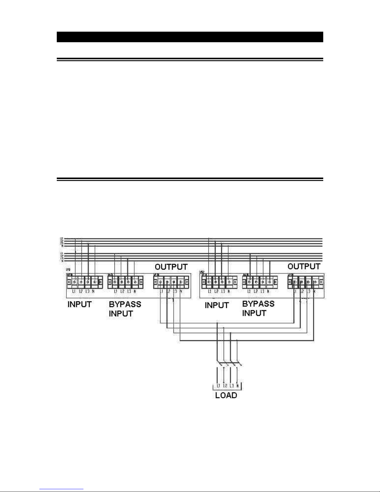
2) Before switching on the UPS’s, make sure that electrical connections have been made as shown in
diagram below:
( OUTPUT CONNECTION OF PARALLEL UPS SYSTEMS )
Page 24
24
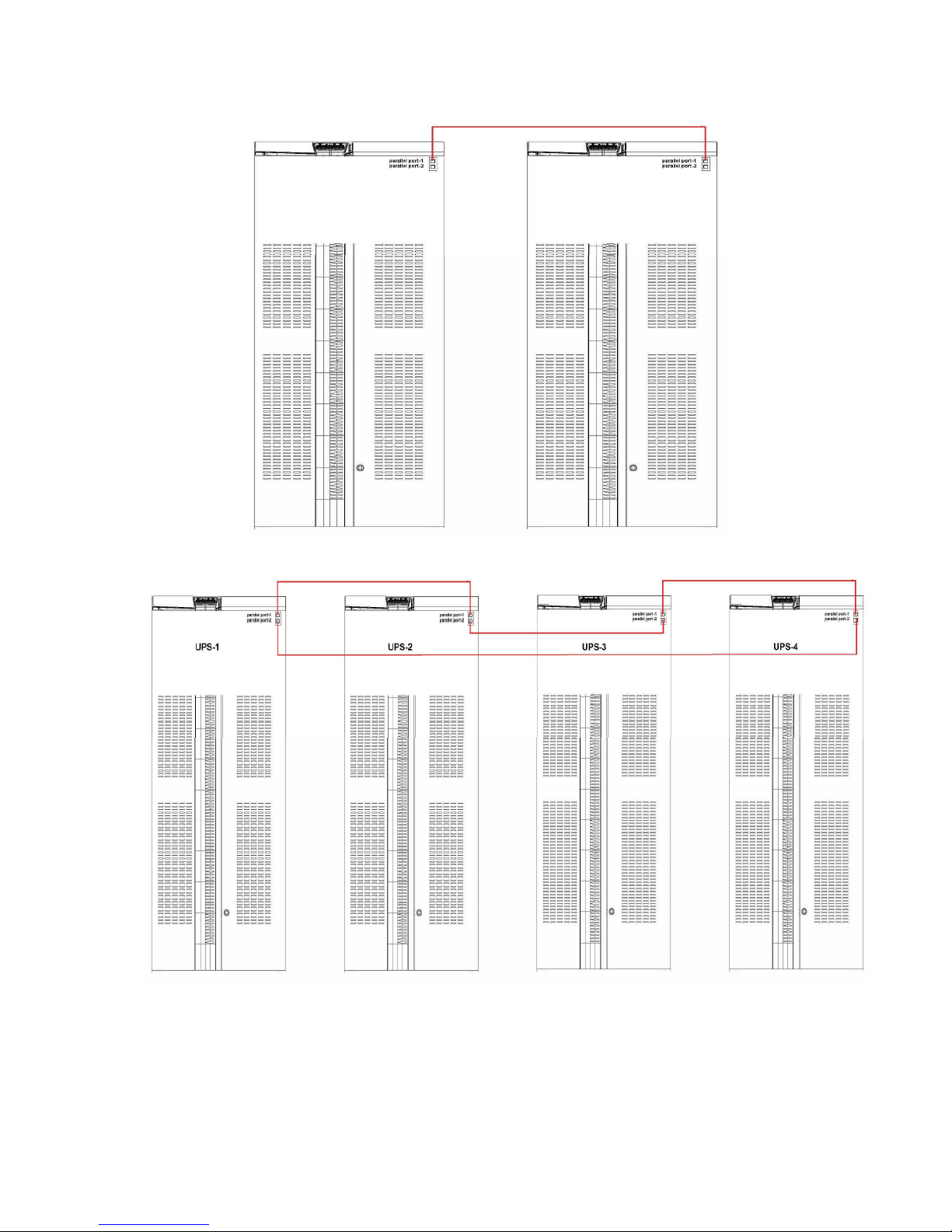
3) The Communication of parallel systems is made through CANBUS. Before starting up the UPS’s, make
the connection of communication cables between UPS’s as per below diagram:
( COMMUNICATION CABLE CONNECTION BETWEEN PARALLEL UPS’s )
CAUTION: Do not remove the communication cables between the UPS’s during parallel operation.
Page 25

25
In case this communication cable is removed or damaged during parallel operation and the
communication is lost then the slave UPS which can not communicate with the master UPS shall
disconnect its output and maintain the OFF position. The other UPS’s shall continue their normal
operation. In such a case, this UPS should be turned off completely in order to insert its communication
cable again and then switched on again. Do not try to insert the communication cable while it is operating.
3) All switches ( F1, F2, F3, F4(optional), F5 and F6 ) should be in “OFF” (“0”) position.
4) Switch on the input Fuse ( F1 ) of the first UPS ( “Master” or “Number 1” labeled UPS) , Inrush Fuse (
F6 ) should be in “OFF” position. ( Note: if the UPS’s are not factory parallel configured, then any of the
UPS’s can be switched on but one should be configured as master and the remaining UPS’s as slave which
will be explained in detail in the following section )
5) Go to the “CONFIGURATION” section from the front panel menu, enter to “MODE” part and
change it from SINGLE to PARALLEL-1 position. This adjustment is made already at factory set UPS’s.
Then please check and control this during commissioning.
6) By using down button on the same Menu, “N” number should be defined. Parallel EVO DSP series
UPS’s operate according to redundancy principle. At the N+1 configurations, the “N” number in this part
is usually - 1 quantity of the parallel operating UPS qty.
On each UPS, this value should be same and correctly entered. Consequently the amount of load that is
allowed to be connected to total system should not be more than ( UPS qty – N ).
“N” can be defined different than “1”. For example it can be defined as 2 at a 4pcs parallel system.
In this case the system will operate as 2+2 redundancy mode and the total load that is going to be
connected to the system can not be more than ( 2x One UPS Power ).
N Value here can be accepted as minimum UPS qty that is required to supply the load where each ups
operates in full load condition. Then ( UPS Qty ) – ( N ) becomes the redundant ups qty in the system.
The system expects to have at least one more ups than N value. Otherwise it shall provide
“REDUNDANCY LOST” alarm. The same alarm shall also appear in case of
Load % x (N+1) / N > 100 situation.
“Redundancy Lost” alarm is just a warning alarm stating that the load amount shared on the
remaining UPS’s is more now, after the failure of one UPS or after a power increase on the load
side. This alarm shall not affect the normal operation of the total system. It indicates that there is not
anymore a redundant UPS in the total system. In case of a failure on one of the remaining UPS’s, the
system will either go to overload, bypass condition or will shut down totally depending on the UPS
quantity in the parallel system.
7) After defining the UPS number and N value from the Configuration Menu, switch off the UPS and
similarly configure the other parallel UPS’s in the system. After this switch off each UPS again. Each UPS
number should be different. Under this menu; Parallel-1, Parallel-2, Parallel-3 and Parallel-4 options are
available. Maximum 4pcs of UPS can be connected in parallel and at the systems where 4 UPS’s operate in
parallel, each UPS’s numbers should be different, defined from 1to 4. (note: if the UPS’s are factory
parallel configured then each UPS’s number has been already defined, please check and control this )
CAUTION: Configuring the parallel UPS’s with same numbers may cause serious damage during
operation. Make sure that each parallel UPS is configured with different numbers.
Page 26

26
8) After completing the configuration the Numbers of each UPS and N values, switch on the F1 input
fuse then F4 Bypass Fuse ( if the UPS is split bypass version ) and F6 Inrush Fuse respectively on each
parallel UPS’s.
After seeing “Normal” message on the LCD panel, F5 Battery fuse can be switched on.
Then the output fuses can be switched on accordingly.
The system ( all UPS’s in parallel configuration ) will start operating from static bypass initially, then they
will start supplying the load from inverter.
9) The initially started up UPS will operate as master and the remaining UPS’s will operate as slave.
According the numbers defined for each ups, on the LCD panel, MAS ( master ) and SLAVE (1,2,3,4)
messages should be observed. On the master unit, candidate master ups is also shown as CX.
C represents the best available master candidate UPS among the slave UPS’s and X represents the number
of the slave UPS. In case the master UPS fails, then this candidate assigned UPS becomes master.
6.3 Procedure for Transferring to Static Bypass
In case it is required to transfer the system to Static Bypass, then this process can be made from the LCD
panel of any UPS in the parallel system. In case static Bypass is activated on any UPS, all the UPS’s will
pass to Static Bypass mode at the same time.
In order to pass to static bypass mode, from the LCD panel menu, go to Commands Menu – Extcmnd.
Select the SYS. TO BYP : ENBLD from the menu. In order to do this selection, pressing ENTER button
will be enough. If Enter button is pressed again from any UPS in system ( does not need to be done from
the UPS where it was enabled at the first time) , then the selection will be changed to DSBLD ( static
bypass disabled, again inverter operation starts ).
6.4 Procedure for Transferring to ( Maintenance ) Manual Bypass
In case it is required to transfer the system to Manual Bypass, then this process can be made from any
UPS in the system. In case Manual Bypass is activated on any one of the UPS, all the UPS’s will pass to
Manual Bypass mode at the same time.
In order to activate the Maintenance Manual Bypass, it is enough to switch on the Maintenance Bypass
switch ( F3 ) on any UPS.
To go back to Inverter operation again, it is necessary to switch off the manual bypass switch of the UPS
which was switched to on position in the first place.
6.5 Procedure for Switching OFF
To switch off the System or one of the UPS’s, follow the procedure below;
1) Switch off the Battery Fuse ( F5 )
2) Switch off the Output Fuse ( F2 )
3) Switch off the Input Fuse ( F1 ) and Inrush Fuse ( F6 )
4) Switch off the Bypass Fuse ( F4 ) if exists
Now the UPS or UPS’s can be separated from the system.
Page 27

27
7 Features and operating limits
7.1 Mains limits for normal operation
Frequency and rms value of the mains input voltage has to be within acceptable limits for the UPS to
operate in normal mode.
Lower limit of the voltage depends on how much the UPS is loaded and it decreases as the load decreases
until it reaches 80 V phase-neutral.
Frequency lower and upper limits and voltage upper limit are fixed.
Voltage and frequency ranges for normal operation are given in the “technical specifications” section of
the manual.
This feature lessens the need to use the batteries. Thus, it increases the battery life and continuity of the
load power.
7.2 By-pass mains limits for bypass operation
Frequency, rms value and total harmonic distortion of the bypass mains input voltage has to be within
acceptable limits for the UPS to operate in bypass mode.
Different rms voltage upper and lower limits are present for the return from another operation mode to
bypass mode. This provides hysteresis and ensures that the device does not change operation mode very
often when the bypass mains rms voltage is close to one of the limits.
Bypass mains limits are software parameters. They can be changed upon request.
7.3 Battery test
This feature enables the user to obtain information about the battery condition. If the batteries have
approached end of their lives, batteries fail.
Battery life depends on several parameters like the number of charge-discharge cycles, discharge depth
and ambient temperature. Battery life greatly decreases as the ambient temperature increases. Therefore it
is recommended to keep the ambient temperature about 20 °C.
To perform a battery test, enter “START B. TEST” in the COMMANDS menu and wait. The UPS will
switch into battery mode, when the test has started. After about ten seconds, UPS will return to the
operation mode before the test. If the batteries pass the test, no alarm will be shown.
If the batteries fail, you’ll receive BATT FAILED message under the ALR submenu. In this case, make
sure that the battery circuit breaker is “ON”/”I”, charge the batteries for minimum 10 hours and repeat
the test. If the alarm persists, consult Technical Service for replacement.
Make sure that the batteries are fully charged and battery circuit breaker is “ON”/”I” before
starting battery test. Otherwise, the batteries will fail even if they are in good condition.
BATT FAILED message will not disappear until another successful test is performed.
Page 28

28
7.4 Overload behavior
While operating in normal or battery mode, the UPS can feed overloads for a limited duration which is
given in the “Technical Specifications” section. After that duration, UPS automatically switches into
bypass mode, if the bypass is enabled and frequency/waveform/rms value of the bypass mains voltage is
within limits. If the overload situation continues in the bypass operation, thermal/magnetic protection
devices may activate and protect the circuit. In this case, all loads on the output will be switched off.
Make sure that the UPS is not overloaded to provide a higher quality supply to the loads.
7.5 Electronic short circuit protection
The UPS attempts to force the thermal/magnetic protection devices between the output terminals and the
short circuited load to open, by supplying current to the short circuited load for a limited duration. The
UPS must be working in battery or normal mode, for this feature to work.
To enable the short circuit protection feature of the UPS, each load shall be fed over a separate
circuit breaker chosen according to the load current. This should provide quick disconnection of
the short circuited load and operation continuity of the other loads. To obtain maximum
protection, the rating of each individual load circuit breaker shall have the minimum value, which
is enough to carry the full load current continuously.
If the protection device fails to open the circuit in a limited time, the UPS stops feeding current to the
output. “VSECFLR” message is shown on the upper left of the LCD.
Page 29
29
8 Communication
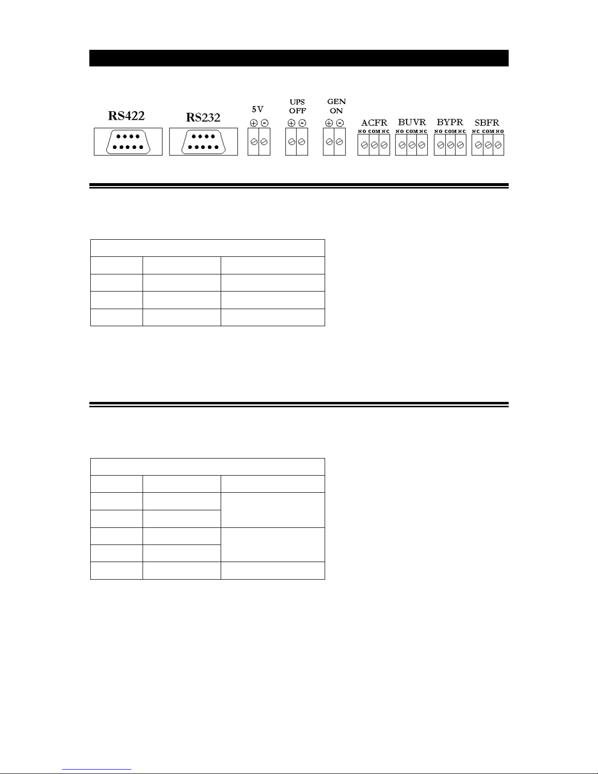
All related terminals are on the communication interface board (A1). Connector layout is as following:
8.1 RS232 Communication
DSUB-9 female connector with the following pin layout shall be used on the UPS side of the connection
cable.
Pin layout is given below:
RS232 PIN LAYOUT
Pin # Signal Name Signal Description
2 RX Receive data
3 TX Transmit data
5 GND Signal ground
RS232 cable shall be shielded and shorter than 15 m.
Only one of the RS232/RS422 communications can be activated at one time. The selection between
RS232 and RS422 communications can be done by setting the COMM parameter in COMMANDS menu,
as desired.
8.2 RS422 Communication
DSUB-9 male connector with the following pin layout shall be used on the UPS side of the connection
cable.
Pin layout is given below:
RS422 PIN LAYOUT
Pin # Signal Name Signal Description
6 A Receive signal pair
5 B
1 Z Transmit signal pair
9 Y
4 GND Signal ground
RS422 cable shall be shielded and shorter than 100 m.
Only one of the RS232/RS422 communications can be activated at one time. The selection between
RS232 and RS422 communications can be done by setting the COMM parameter in COMMANDS menu,
as desired.
Page 30
30
8.3 Digital Inputs (UPS OFF and GEN ON)
Voltage to be applied to the digital inputs is 5V DC. Maximum current drawn by each input is 1 mA.
5V DC supply provided on the communication interface board can be used to supply both digital inputs.
Pay attention to the polarity of the voltages applied to the digital input terminals.
Input Function
UPS OFF
If the UPS OFF input is set high by applying 5V DC voltage on the related
terminals, UPS stops generating the output voltage and stops feeding the load.
When the voltage on the digital input is removed, the UPS starts up according
to the normal procedure.
GEN ON
If the GEN ON input is set high by applying 5V DC voltage on the related
terminals, UPS smoothly increases the current drawn from the generator
during transitions from battery mode to normal mode.
8.4 Free Contact Communication
Free contact relay connection cables shall have a cross-section of 1.5 mm2.
Maximum voltage to be applied to the relay contacts is 42V AC rms (sinus) or 60 Vdc. Maximum
contact current depends on the applied voltage and the load characteristic. Both maximum
voltage and maximum contact current corresponding to the applied voltage shall not be
exceeded.
Maximum allowed resistive contact currents for several voltages are given on the table below:
Applied voltage Maximum contact current for resistive load
Up to 42 V AC 16 A
Up to 20 V DC 16 A
30 V DC 6 A
40 V DC 2 A
50 V DC 1 A
60 V DC 0.8 A
Each relay has both a normally open (NO) and a normally closed (NC) contact. One end of these contacts
is common. Normal states of the relay contacts are shown on the figure at the beginning of the
“communications” section.
Relay functions are described below:
Relay Function
ACFR (AC failure relay)
Contacts change position if the rms value or frequency of the
mains voltage is beyond their limits.
BYPR (Bypass relay)
Contacts change position if the UPS is working in the bypass
mode
BUVR (Battery under voltage relay)
Contacts change position if the battery voltages are critically low
to feed the load and the load power is about to be interrupted
SBFR (secure bus failure relay) Contacts change position, if the output voltage disappears
Page 31
31
9 Maintenance
Batteries, fans and capacitors shall be replaced at the end of their lives.
Hazardous voltage and high temperature metal parts inside even if the UPS is disconnected.
Contact may cause electric shock and burns. All operations except replacing battery fuses shall
be carried out by the authorized technical personnel only.
Some parts inside the UPS (terminals, EMC filters and measurement circuits) are still energized
during maintenance bypass operation. In order to isolate all UPS parts, circuit breakers on mains
and bypass mains distribution panels feeding the UPS and circuit breakers on external battery
cabinet shall be brought to “OFF/0” position. Internal batteries shall also be isolated from the
system.
9.1 Battery fuses
Bringing the battery circuit breaker to “I”/“ON” position before seeing “NORMAL” message on the
LCD may cause battery fuses to blow out.
Battery fuses shall only be replaced with Gould 22x58 aR 660V ultra fast fuse of same rating or
equivalent.
9.2 Batteries
Battery life strongly depends on the ambient temperature. There are also other factors like the number of
charge-discharge cycles and discharge depth.
Battery life is between 3-10 years if the ambient temperature is between 10 – 20 °C. Performing battery
test can provide you with information about battery condition. (See “battery test” section for more
information on battery test)
Danger of explosion and fire if the batteries of the wrong type or number are used.
Do not dispose of batteries in a fire. The batteries may explode. Do not open or mutilate
batteries. Released electrolyte is harmful to the skin and eyes. It may be toxic.
9.3 Fans
The life of fans used to cool the power circuits depends on the usage and environmental conditions.
Preventive replacement by authorized technical personnel every four years is recommended.
9.4 Capacitors
The life of the electrolytic capacitors on the DC bus and the capacitors used for output and input filtering
purposes depends on the usage and environmental conditions.
Preventive replacement by authorized technical personnel every five years is recommended.
Page 32

32
10 Troubleshooting
This section gives information about the procedures which shall be performed in case of abnormal
operation. If you fail to fix the problem consult authorized technical service with the following
information:
Model and serial number of the UPS, which can be found on the nameplate on the rear of the
UPS. This information is also available in the test report provided with the UPS.
ALR and ST codes in the ALARMS menu
Hazardous voltage and high temperature metal parts inside even if the UPS is disconnected.
Contact may cause electric shock and burns. This unit is to be served by authorized technical
personnel only.
Alarms and problems you may encounter during operating the UPS are given in the table below.
If you have noticed an abnormality in operation; check the protective earth connections, examine the
circuit breaker positions, read alarms from the ALARMS menu and refer to the table. Apply all
suggestions corresponding to each alarm. If your issue is excluded or the suggested actions do not solve
your problem, consult the Technical Service.
Alarm Possible Cause Action
BYP BAD alarm is present
Bypass mains voltage is different
than the inverter reference signal
Make sure that the bypass circuit breaker is
“I"/"ON"(if the UPS has no separate bypass
mains input, make sure that the input circuit
breaker is "I"/"ON".
(e.g. its beyond its limits or it has a
total harmonic distortion > %10)
VBYP HIGH alarm is
present
Bypass mains voltage is higher
than its upper limit
Check if the bypass mains voltage is in
specified limits
VBYP LOW alarm is
present
Bypass mains voltage is lower
higher than its lower limit
BYP SYN FL alarm is
present
Frequency of bypass mains voltage
is beyond the frequency range for
bypass operation or bypass mains
voltage is very low
BYP SEQ FL alarm is
present
Phase sequence of bypass mains
voltages is not OK
Phase sequence of the separate bypass mains
input shall be changed. Consult technical
service
MAN BYP alarm is present Manual bypass switch is "ON"
Check the position of the manual bypass
switch.
INV OVTE alarm is present
Inverter block temperature is very
high
Check if there is an overload and remove the
excessive load.
Measure the ambient temperature near UPS.
Make sure that the temperature is in specified
limits.
Check if the fans are running.
OUT OVLD alarm is
present
Rms current drawn from any of
the output lines exceeds its
nominal value
Check if there is an overload and remove the
excessive load. If the total power drawn by the
load is less than the nominal power, make sure
that it is distributed evenly between phases.
Page 33

33
Alarm Possible Cause Action
INV BLKD alarm is present
Inverter operation is automatically
stopped due to a fault
Consult Technical Service
VSEC NOK alarm is
present
(Output voltage is beyond
its limits)
The UPS may not started up yet.
This alarm is permanent if the
UPS is intended to be started with
the bypass blocked or when the
bypass mains is not in specified
limits
Make sure that all circuit breakers is "I"/"ON"
Check if there is any other alarms and apply the
related suggestions
Examine the preferences, check the mains
voltages and read the "modes of operation"
section of the manual. Determine if the
combination of line voltages and preferences
does inhibit the UPS operation.
The UPS may have stopped to
feed the load because the
combination of the mains
conditions ant the user preferences
made from the COMMANDS
menu does not allow the UPS to
work in any of the operation
modes.(e.g. if inverter is disabled
and both input and bypass mains
voltages are not acceptable or if
the rectifier is disabled when the
bypass voltage is not in specified
limits or batteries may be
discharged during a prolonged
outage)
The output circuit breaker is
"0"/"OFF"
VIN HIGH alarm is present
Input line/neutral voltage is higher
than its upper limit
Check if the bypass mains voltage is in
specified limits
VIN LOW alarm is present
Input line/neutral voltage is lower
than its lower limit
IN SYN FLR alarm is
present
Frequency of mains voltage is
beyond the frequency range for
normal operation or mains voltage
is very low
Check if the mains voltage is in specified limits
IN SEQ FLR alarm is
present
Phase sequence of input mains
voltages is not OK
Phase sequence of the mains input shall be
changed. Consult technical service
RECT OVTE alarm is
present
Rectifier block temperature is very
high
Measure the ambient temperature near UPS.
Make sure that the temperature is in specified
limits.
Check if the fans are running.
RECT OVLD alarm is
present
RMS current drawn from any of
the input lines exceeds its nominal
value
Check if there is an overload and remove the
excessive load.
VDC HIGH alarm is
present
Any of the DC bus voltages is
higher than its upper limit
Consult Technical Service
VDC LOW alarm is present
Any of the DC bus voltages is
lower than its lower limit
Means that the batteries had
discharged. It is removed when the
rectifier resets.
If you encounter this alarm during start-up,
check if the inrush circuit breaker is "ON"/"I".
Charge the batteries, perform battery test and
check if the alarm has removed.
RECT BLKD alarm is
present
Rectifier operation is automatically
stopped due to a fault
Consult Technical Service
Page 34

34
Alarm Possible Cause Action
VDC NOK alarm is present
Any of the DC bus voltages
approaches its lower or upper
limits
May mean that the batteries have
approached to their lower voltage
limit and are almost empty.
Charge the batteries, and check if the alarm has
removed.
AMB OVTE alarm is
present
Ambient temperature exceeds its
upper limit
Measure the ambient temperature near UPS.
Make sure that the temperature is in specified
limits.
GEN ON alarm is present
Generator friendly operation is
activated (digital input “GEN
ON” is set high)
Check the "GEN ON" input
UPS OFF alarm is present
Emergency stop is activated
(digital input “UPS OFF” is set
high)
Check the "UPS OFF" input
BATT FAILED alarm is
present
Batteries failed in the battery test
Perform the test again when the batteries have
been charged for a long time and the battery
circuit breaker is "I"/"ON"
Check if the alarm continues
BATT C. OPEN alarm is
present
(A difference between
battery & DC bus voltage is
present )
Battery circuit breaker (F5) is
probably open ("0"/"OFF")
Make sure that the battery circuit breaker is
"I"/"ON". If not do the following:
-Check the rectifier preference and enable the
rectifier.
-Make sure that the input mains voltage is in
specified limits.
-Make sure that the UPS has switched to
normal mode and close the battery circuit
breaker.
The battery circuit breaker of the
external battery cabinet is open
("0"/"OFF")
Make sure that the battery circuit breaker of the
external battery cabinet is "I"/"ON". If not do
the following:
-Check the rectifier preference and enable the
rectifier.
-Make sure that the input mains voltage is in
specified limits.
-Make sure that the UPS has switched to
normal mode and close the battery circuit
breaker.
Battery fuses of the battery circuit
breaker (F5) or the external battery
cabinet may have blown
Check if the battery fuses are blown. Replace if
necessary (see maintenance section)
There is no battery in the system
Batteries shall be supplemented. Consult
Technical Service
Page 35

35
11 Technical Specifications
MODELS
Apparent power [kVA] 10 15 20 30 40 60 80 100
ENVIRONMENTAL
Storage temperature range
[°C] -25 to +55 (15 - 40 recommended for longer battery life)
Operating temperature
range [°C] 0 to +40 (20 - 25 recommended for longer battery life)
Relative humidity range % 0 - % 95 (non condensing)
Max. altitude without
derating [m] 1000
Protection level IP 20
Maximum
power
dissipation
[W] 800 960 1280 1920 2560 3840 5120 6400
[Btu] 2730 3277 4369 6553 8737 13106 17475 21843
[kcal/h] 688 825 1100 1650 2200 3302 4403 5503
ELECTRICAL
Mains Input
Number of phases 3P+N+PE
Nominal voltage [V] 380 / 400 / 415 (line-line)
Voltage range
for normal
operation (line
to neutral) [V]
Lower
limit
(depends
on the
load
level)
187 @ %100 load ( line- neutral )
120 @ %64 load ( line- neutral )
80V@ %42 load ( line- neutral )
Upper
limit 280
Nominal frequency [Hz] 50 / 60
Frequency range [Hz] +/-10%
Nominal
current [A]
wave
form sinusoidal
rms value
*(2) 13 20 26 40 53 79 105 131
Maximum
current [A]
wave
form sinusoidal
rms value
17 23 30 47 61 95 125 158
OUTPUT
Performance classification
according to IEC 62040-3
VFI-SS-111
Number of phases 3P+N+PE
Nominal voltage [V] 380 / 400 / 415 (line-line)
Static voltage
regulation normal
<%1
@ %100 linear
load battery
Nominal frequency [Hz] 50 / 60
Free running frequency
[Hz] ± % 0.01
Voltage THD @ rated
linear load <%3
Nominal apparent power
[kVA] 10 15 20 30 40 60 80 100
Maximum load p. f. 0.8
Nominal active power [kW]
8 12 16 24 32 48 64 80
Nominal current [A] at
380V 15.2 22.7 30.3 45.5 60.6 91 121 151
Load crest factor @ rated
power 3:1
Overload duration >1min @ %150 load
Efficiency (normal
operation) @rated linear
load with 0.8 PF
>92
Page 36

36
STATIC BY-PASS LINE
Number of phases 3P+N+PE
Voltage range (line
- neu
tral)
[V]*(1) 220 V /230V /240V ±%10
Frequency range [Hz] *(1) 47-53
Nominal apparent power
[kVA] 10 15 20 30 40 60 80 100
Nominal current [A] 15.2 22.7 30.3 45.5 60.6 91 121 151
Transfer duration [ms] 0
BATTERIES
Battery type Sealed lead acid, 12 V
Number of batteries 2x31
Nominal battery voltage [V]
2x372
Stored energy
time @
nominal load
with standard
internal
batteries*(2)
7Ah 14m 6m 4,5m - -
9 Ah 25m 10m 7m 2,5m -
STANDARDS
Safety EN 62040-1-2, EN 60950-1
Performance EN 62040-3
EMC EN 50091-2
Product Certification CE
COMMUNICATIONS
Free contact communication (AC failure, battery under voltage, bypass and output failure)
Serial communications (RS232, RS 422)
Two digital inputs for remote shut down of the UPS and generator operation feedback
Isolated auxiliary 5V supply for digital inputs
OTHERS
Manual by-pass with 0 transfer time
Electronic short circuit protection
Over temperature and over current protection
Liquid crystal display (LCD)
Mimic front panel
*(1) These are software parameters. They can be changed upon request
*(2) Batteries shall be fully charged in order to provide these values
Page 37

37
12 Internal Battery Location & Connection Instructions
1) Take out all the drawers outside of the UPS,
2) Place the batteries of the drawer-1 vertically as shown in the drawing. Make the cable link
connections between 1st battery to 7th batteries. Connect the red cable to the positive pole of the
1st battery. Then connect the 20cm cable to the negative pole of the 7th battery. Insert the drawer
to the upper shelf and place it on the left side where the poles of the batteries face inside as
shown in the diagram.
3) Place the batteries of the drawer-2 vertically as shown in the drawing. Make the cable link
connection between 15th to 21st batteries. Connect the 110cm cable to the negative pole of the
21st battery. Insert the drawer to the upper shelf and place it on the right side where the poles of
the batteries face inside as shown in the diagram.
4) Place the batteries of the drawer-3 horizontally as shown in the drawing. Make the cable link
connection between 8th to 14th batteries. Connect the number 14 point of the 55cm cable.
Connect and fix the battery holder metal sheet to the drawer. Insert the drawer to the upper shelf
and place it in the middle of drawers 1 and 2.
5) Make the connection between 7th and 8th batteries with 20cm cable.
6) Make the connection between 14th and 15th batteries with 55cm cable.
7) Place the batteries of the drawer-4 vertically as shown in the drawing. Make the cable link
connections between 22nd battery to 28th batteries. Make the connection between the 21st and 22nd
battery with the 110cm cable. Then connect the 28 numbered 20cm cable to the 28th battery.
Insert the drawer to the middle shelf and place it on the left side where the poles of the batteries
face inside as shown in the diagram.
8) Place the batteries of the drawer-5 vertically as shown in the drawing. Make the cable link
connections between 35th battery to 41st batteries. Connect the 41 numbered cable to the negative
pole of the 41st battery. Insert the drawer to the middle shelf and place it on the right side where
the poles of the batteries face inside as shown in the diagram.
9) Place the batteries of the drawer-6 horizontally as shown in the drawing. Make the cable link
connection between 29th to 34th batteries. Connect the positive blue neutral cable to 32nd battery
and negative blue neutral cable to 31st battery. These are the middle points. Make the connection
between 34th and 35th batteries. Connect and fix the battery holder metal sheet to the drawer.
Insert the drawer to the middle shelf and place it in the middle of drawers 4 and 5.
10) Make the connection between 28th and 29th batteries with 20cm cable.
11) Place the batteries of the drawer-7 vertically as shown in the drawing. Make the cable link
connections between 42nd battery to 48th batteries. Make the connection between 41st battery and
42nd battery. Then connect the 20cm cable to the 48th battery. Insert the drawer to the bottom
shelf and place it on the left side where the poles of the batteries face inside as shown in the
diagram.
12) Place the batteries of the drawer-8 vertically as shown in the drawing. Make the cable link
connections between 56th battery to 62nd batteries. Connect the main minus black cable to the
62nd battery. Insert the drawer to the bottom shelf and place it on the right side where the poles
of the batteries face inside as shown in the diagram.
13) Place the batteries of the drawer-9 horizontally as shown in the drawing. Make the cable link
connection between 49th to 55th batteries. Connect the 55 numbered cable to the 55th battery.
Connect and fix the battery holder metal sheet to the drawer. Insert the drawer to the bottom
shelf and place it in the middle of drawers 7 and 8.
14) Make the connection between 55th and 56th batteries.
Make the connection between 48th and 49th batteries.
15) Check the battery voltage between B- and 0 terminals ( ~ 372V ), B+ and 0 terminals (~ 372V ),
B- and B+ ( 744V ) and confirm the observe of the approximate correct DC voltage values.
Page 38
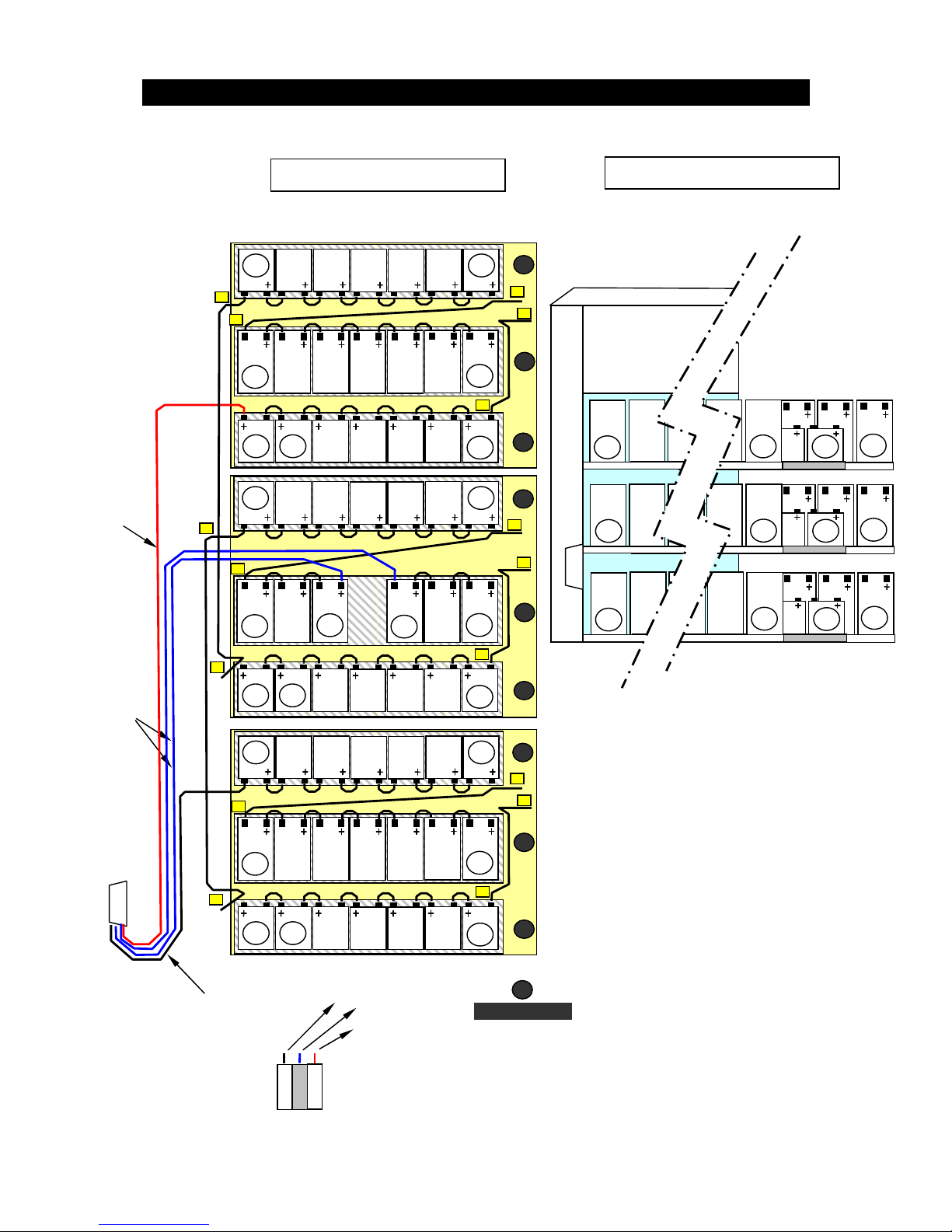
38
13 Internal Battery Location & Connection Diagram
Internal Battery Location is available at the UPS’s from 10kVA to 30kVA.
Red B+
Blue
Black B
-
110cm
160cm
70cm
145cm
56
42 43
48
55
49
62
56
55
49
48
35
22 23
28
34
29
41
35
34
29
28
8cm
15
55cm
20cm
1 2
7
14
8
21
15
14
8
7
32
31
22
21
42
41
110cm
7
9
8
4
6
5
1
3
2
1
DRAWER
NO
49
48 56
29
28 35
8
7 15 1
22
42
TOP VIEW OF SHELVES
SIDE VIEW OF SHELVES
N3 B-
Red B+
Blue 0V
Black B
-
B+
 Loading...