

Tecnoware EVO DSP PLUS TM 10 KVA, EVO DSP PLUS TM 15 KVA, EVO DSP PLUS TM 20 KVA User Manual
Uninterruptible Power Supply
EVO DSP PLUS TM 10 KVA
EVO DSP PLUS TM 15 KVA
EVO DSP PLUS TM 20 KVA
User’s manual
Manuale utente


Index
User’s Manual - English ........................................................................ 1
Safety Warnings ................................................................................. 1
1 Introduction ................................................................................. 2
2 General Characteristics ................................................................... 3
3 Receipt and site selection ................................................................ 3
4 Operating Modes ........................................................................... 4
4.1 UPS Power On ......................................................................... 5
4.2 NORMAL Mode ......................................................................... 5
4.3 BATTERY Mode ........................................................................ 6
4.4 BYPASS Mode .......................................................................... 6
4.5 NO-OUTPUT Mode .................................................................... 7
4.6 BATTERY TEST mode ................................................................. 8
4.7 ECO Mode .............................................................................. 8
4.8 CONVERTER FREQUENCY Mode ...................................................... 9
4.9 WARNING STATUS .................................................................... 10
4.10 FAULT STATUS ........................................................................ 10
5 External Description ...................................................................... 11
5.1 Front Panel ........................................................................... 11
5.1.1 Graphic LCD Panel ....................................................................... 12
5.1.2 Buttons.................................................................................... 14
5.1.3 LED Indicators ............................................................................ 14
5.1.4 Acoustic Alarm ........................................................................... 14
5.2 Rear Side .............................................................................. 15
5.2.1 Input/Output Terminals ................................................................ 16
5.2.2 EPO (Emergency Power Off) ........................................................... 17
6 Electrical Installation ..................................................................... 17
6.1 Installation ............................................................................ 18
7 First Start Up ............................................................................... 20
8 Functioning ................................................................................. 20
8.1 Turning ON and OFF ................................................................. 20
8.2 Low Battery and Automatic Restart ............................................... 21
8.3 Load Testing .......................................................................... 21
8.4 Manual Bypass ........................................................................ 22
8.5 Battery Test .......................................................................... 22
8.6 Operation in Warning Status ....................................................... 23
8.7 Operation in Fault Mode ............................................................ 24
8.8 Operating Procedures for Parallel System ........................................ 25
8.8.1 Parallel System Connection ............................................................ 25
8.8.2 Add one new unit into the Parallel System .......................................... 26
8.8.3 remove one unit from the Parallel System .......................................... 26
9 Communication Interfaces ............................................................... 26
10 Technical Characteristics ................................................................ 27
11 Maintenance ................................................................................ 29
11.1 UPS Cleaning ......................................................................... 29
11.2 Battery ................................................................................ 29
11.3 Operator Safety ...................................................................... 29
12 Troubleshooting ........................................................................... 30
Conformity to the European Directives ................................................... 32
Product Disposal ............................................................................... 32
Lead Batteries ................................................................................. 32

Indice
Manuale Utente – Italiano ................................................................... 33
Avvisi di Sicurezza ............................................................................ 33
1 Introduzione ............................................................................... 34
2 Caratteristiche Generali................................................................. 35
3 Ricevimento e Collocazione ............................................................ 35
4 Modi di Funzionamento ................................................................. 36
4.1 Accensione UPS ....................................................................... 37
4.2 Modo NORMALE ....................................................................... 37
4.3 Modo BATTERIA ....................................................................... 38
4.4 Modo BYPASS .......................................................................... 38
4.5 Modo NO-OUTPUT .................................................................... 39
4.6 Modo BATTERY TEST ................................................................. 40
4.7 Modo ECO ............................................................................. 40
4.8 Modo CONVERTITORE DI FREQUENZA .............................................. 41
4.9 STATO DI ALLARME ................................................................... 42
4.10 STATO DI GUASTO (FAULT) ......................................................... 42
5 Descrizione Esterna ...................................................................... 43
5.1 Pannello Frontale .................................................................... 43
5.1.1 Pannello LCD Grafico .................................................................... 44
5.1.2 Pulsanti .................................................................................... 46
5.1.3 Indicazioni a Led ......................................................................... 46
5.1.4 Allarme Acustico ......................................................................... 46
5.2 Pannello Posteriore .................................................................. 47
5.2.1 Morsettiera d’Ingresso/Uscita .......................................................... 48
5.2.2 EPO (Emergency Power Off) ............................................................ 49
6 Installazione Elettrica ................................................................... 49
6.1 Installazione .......................................................................... 50
7 Prima Accensione ......................................................................... 52
8 Funzionamento ........................................................................... 52
8.1 Accensione e Spegnimento ......................................................... 52
8.2 Fine Autonomia e Riaccensione Automatica ...................................... 53
8.3 Controllo del Carico ................................................................. 53
8.4 Bypass Manuale ....................................................................... 54
8.5 Test Batteria .......................................................................... 54
8.6 Segnalazioni di Allarme ............................................................. 55
8.7 Segnalazioni di Guasto .............................................................. 56
8.8 Procedure Operative per Sistemi Parallelo ....................................... 57
8.8.1 Collegamenti per Sistema Parallelo ................................................... 57
8.8.2 Aggiungere un nuovo UPS nel Sistema Parallelo ..................................... 58
8.8.3 Rimuovere un UPS dal Sistema Parallelo.............................................. 58
9 Interfacce di Comunicazione ........................................................... 58
10 Caratteristiche Tecniche ................................................................ 59
11 Manutenzione ............................................................................. 61
11.1 Pulizia dell’UPS ...................................................................... 61
11.2 Batterie ................................................................................ 61
11.3 Sicurezza dell’Operatore ........................................................... 61
12 Anomalie ed Interventi .................................................................. 62
Conformità alle Direttive Europee ........................................................ 64
Smaltimento del Prodotto ................................................................... 64
Batterie al Piombo ............................................................................ 64
ENGLISH
UPS EVO DSP PLUS TM 1 User’s manual
User’s Manual - English
Safety Warnings
Read this manual carefully and completely before installing and using the TECNOWARE EVO DSP
PLUS TM Uninterruptible Power Supply, which, from here after, will also be referred to as UPS.
The UPS must be used only by properly trained personnel. To ensure correct and safe
operations, it is necessary that operators and maintenance personnel observe the general
safety Standards as well as the specific instructions included in this manual.
Risk of electric shock: do not remove the cover. The UPS contains internal parts which are at a
high Voltage and are potentially dangerous, capable of causing injury or death by electric
shock.
There are no internal parts in the UPS which are user serviceable. Any repair or maintenance
work must be performed exclusively by qualified technical personnel authorized by
TECNOWARE. TECNOWARE declines any responsibility if this warning is disregarded.
The electric installation has to be done by qualified personnel. Follow all the Safety Standards
(CEI Standards in Italy or IEEE elsewhere) for the Input/Output connections and for the right
section of Input/Output cables.
It is compulsory to ground the UPS according to Safety Standards.
Risk of electric shock at the Output lines when the UPS is ON.
Risk of electric shock at the Output lines while the unit is connected to the AC utility line.
For respect of the Safety Standards is necessary the presence of a differential circuit breaker
between UPS Output lines and the loads.
We recommend to use a dedicate AC Input/Output power line for the UPS.
Do not obstruct ventilation slots or holes and do not rest any object on top of the UPS.
Do not insert objects or pour liquids in the ventilation holes.
Install the UPS indoors, in a protected, clean and moisture-free environment.
Do not expose to the direct sun light.
Do not keep liquids, flammable gases or corrosive substances near the UPS.
ENGLISH
User’s manual 2 UPS EVO DSP PLUS TM
1 Introduction
UPS EVO DSP PLUS TM (UPS means Uninterruptible Power Supply) is the result of constant technological research
aimed at obtaining the best performance at the lowest cost.
UPS EVO DSP PLUS TM is an advanced ON-LINE UPS built specifically to protect your computer from any
irregularities in the AC line (for example blackouts, brownouts, over voltages, micro-interruptions), which often
cause damage to hardware and software.
All that is possible because UPS EVO DSP PLUS TM is a Double-Conversion ON-LINE UPS.
Under normal AC line condition UPS EVO DSP PLUS TM provides an automatic Output Voltage regulation from the
Rectifier and Inverter blocks and filters out frequently occurring electrical disturbances (high Voltage transients,
spikes, interferences, etc.), thus protecting the devices connected to its outlets. During a power failure, UPS EVO
DSP PLUS TM continues supplying adequate AC power (with a true sine wave) to all connected devices through its
internal batteries and by its DC/AC converter (Inverter).
UPS EVO DSP PLUS TM protects the devices from accidental overload or Inverter fault by an Automatic Bypass that
directly connects the AC Input line with its outlets.
UPS EVO DSP PLUS TM models are factory-equipped with RS-232 and USB interfaces, which may be used for notify
to a computer a power failure or a Low Battery condition: this allows automatic data backup during an extended
blackout with the most common operating systems (Windows, Linux, Unix, etc). Thanks to Interfaces, UPS EVO DSP
PLUS TM can communicate the several made measurements (Input/Output Voltage, batteries, absorption,
Frequency, etc.), and can also be programmed in order to start-up or shutdown automatically at fixed times.
Read this manual carefully before using the UPS EVO DSP PLUS TM; it includes important
safety warnings and useful advices for correct use and installation.
UPS EVO DSP PLUS TM is constantly being developed and improved: consequently, your unit may differ somewhat
from the description contained in this manual.
This manual includes the following models:
• UPS EVO DSP PLUS TM 10 KVA
• UPS EVO DSP PLUS TM 15 KVA
• UPS EVO DSP PLUS TM 20 KVA
In this manual UPS EVO DSP PLUS TM will simply be referred to as UPS.
EVO DSP PLUS TM models are made from a single unit that contains the electronics parts and the batteries.
However EVO DSP PLUS TM models are predisposed to the connection with external BATTERY BOX units in order to
increase the autonomy.

ENGLISH
UPS EVO DSP PLUS TM 3 User’s manual
2 General Characteristics
UPS EVO DSP PLUS TM has all the advanced features, which guarantee maximum reliability and safety:
• Double-Conversion ON-LINE Transformerless technology
• Sinusoidal wave generated by an IGBT Inverter
• Output Voltage regulation ±1%
• Protection from overload and short circuits
• Automatic Bypass to protect from accidental overload or Inverter fault
• Start-up even under Mains OFF conditions
• Automatic protection when Battery is low
• Automatic restart, following an automatic shut-down due to Low Battery, once AC utility power comes
back on
• Selectable Input Frequency (50/60 Hz)
• Graphic LCD panel for visualization of the Input and Output Voltage measurements, batteries Voltage,
percentage of load, Frequency, alarms, overload, fault and path of energy flow
• Acoustic signals of various kinds indicating alarm situations
• Available settings of all the UPS parameters by user through front panel pushbuttons and graphic LCD
panel
• SNMP Adapter (optional)
• EPO (Emergency Power OFF)
• Communication with the computer through RS-232 and USB interfaces
• Available extended autonomy by adding external Battery Boxes
• Manual Bypass for maintenance
• Parallel operating mode up to 3 UPS’s (optional)
• ECO functioning mode (selectable)
• Frequency Converter functioning mode (selectable)
• High efficiency
• Maximum reliability
• Smart design and easy to use
3 Receipt and site selection
Carefully remove the UPS from its packaging, and carry out a meticulous inspection. We recommend keeping the
original packaging in a secure place, in case you need to send the UPS for maintenance purposes. In case of
transport damage, notify the carrier and dealer immediately.
We recommend paying attention to the below points in order to choose a correct placement for your UPS:
• The UPS is designed to operate in a protected environment (e.g. offices). We therefore recommend
installing it in a place with very little or no humidity, dust or smoke.
• When the UPS is brought from a cold place to a warmer place, humidity in the air may cause condensation
in the UPS. In this case, allow UPS to stand for two hours in the warmer place before beginning with the
installation.
ENGLISH
User’s manual 4 UPS EVO DSP PLUS TM
• In all circumstances, see the “Technical Characteristics” chapter for environmental specifications and
check that the selected area meets these criteria.
• During normal operation the UPS discharges a minimal amount of heat. So it is necessary to leave at least
25 cm of unobstructed space all around the UPS in order to keep it properly ventilated.
• Do not obstruct ventilation holes.
• Do not insert objects or pour liquids in the ventilation holes.
• Do not rest any object on top of the UPS.
• Do not keep liquids, flammable gases or corrosive substances near the unit.
• Install the UPS on a properly tiled floor. Avoid the installation on a floor that is not tiled flat.
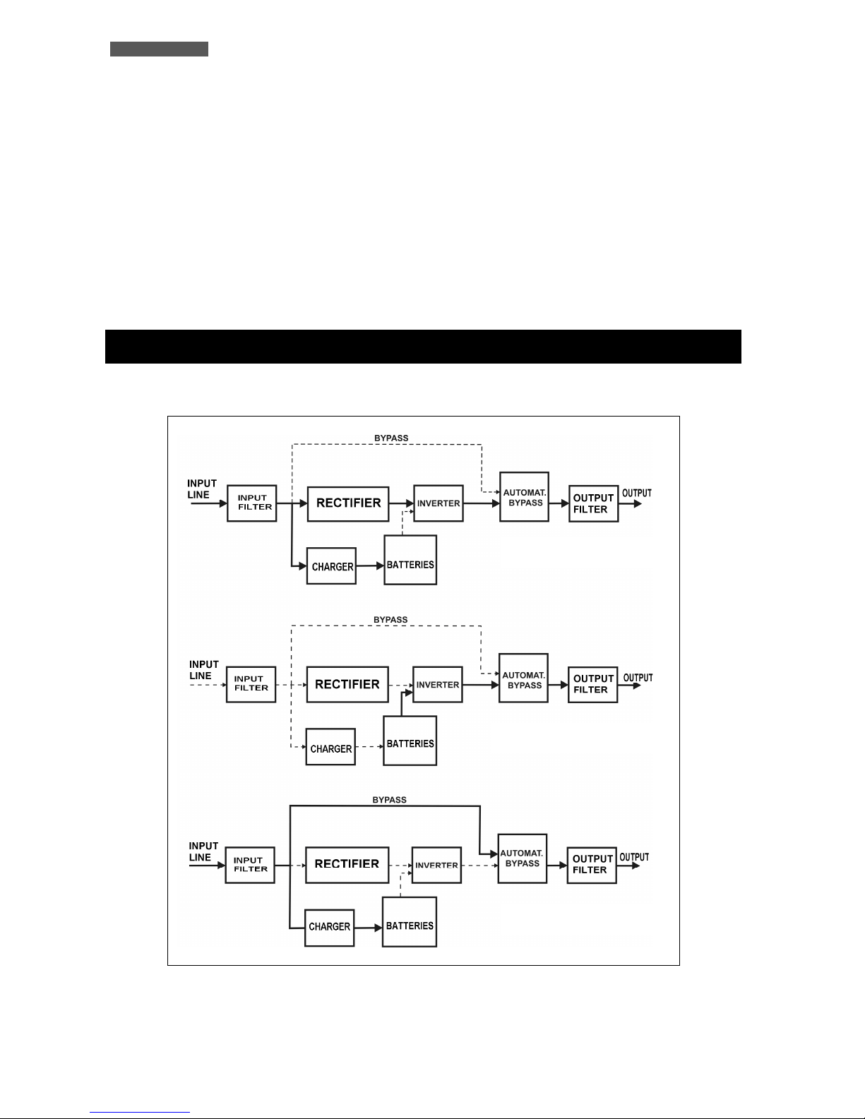
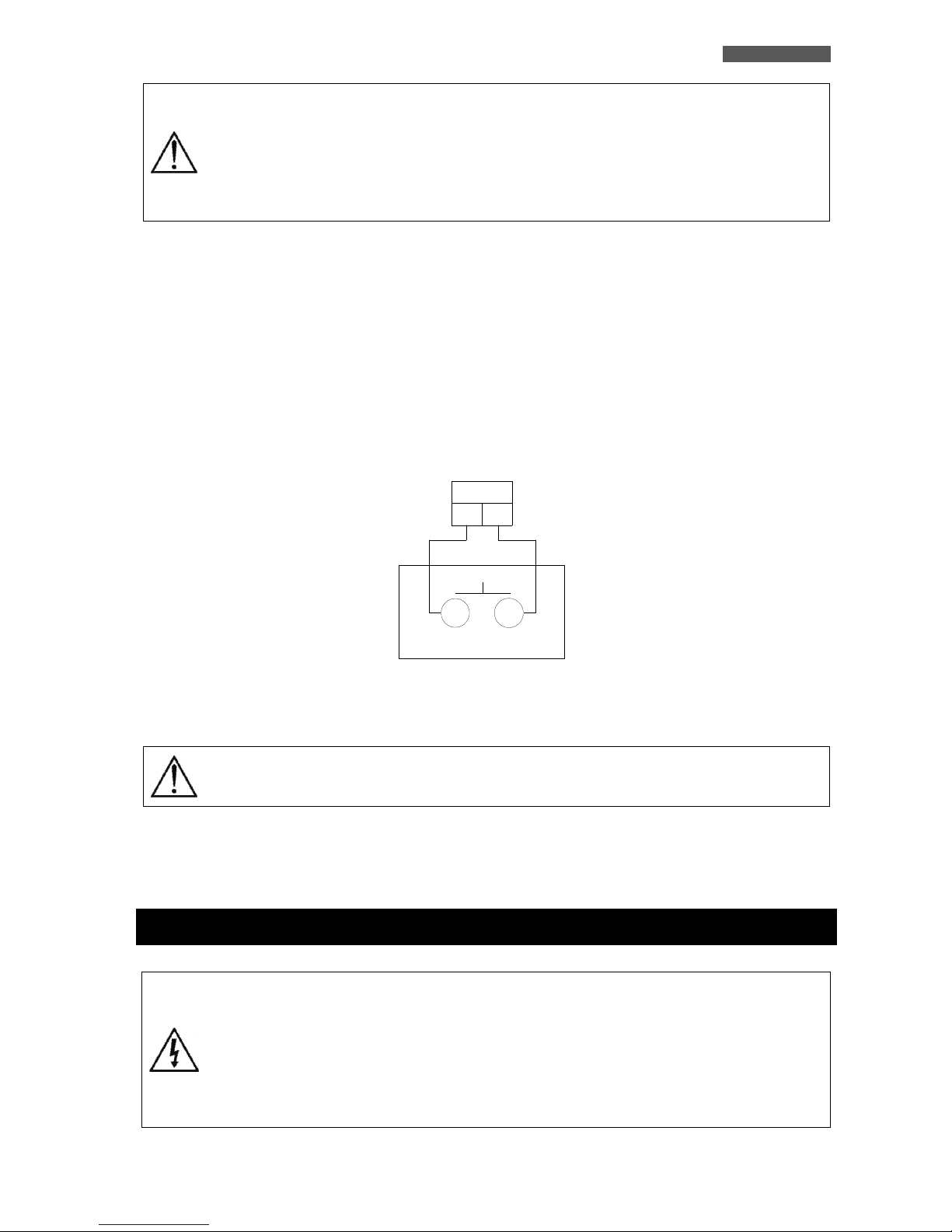
4 Operating Modes
Figure 1 – Operating modes
BATTERY MODE
NORMAL MODE
BYPASS MODE
ENGLISH
UPS EVO DSP PLUS TM 5 User’s manual
Following pages shows LCD display for operating modes and status.
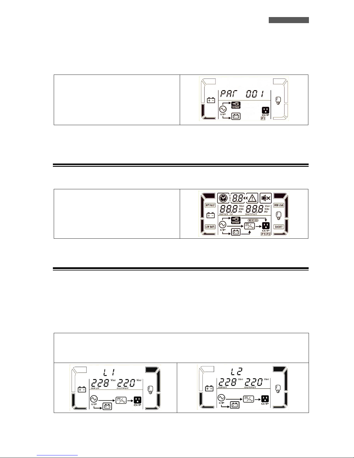
If the UPS is in normal operation, it will show four screens one by one, which represents 3 phase input voltage (L1,
L2, L3) and frequency in turns.
If Parallel UPS Systems are successfully set up, it will
show one more screen with “PAR”.
The master UPS will be default assigned as “001” and
slave UPSs will be assigned as either “002” or “003”.
The assigned numbers may be changed dynamically in
the operation
Parallel screen
4.1 UPS Power On
When UPS is powered on, it will enter into this mode for a few seconds as initializing the CPU and system.
All the icons on the graphic LCD panel are ON.
All the leds are ON.
4.2 NORMAL Mode
The UPS typically works in Normal mode: Input mains power is available and its amplitude is within specifications.
Please refer to figure 1.
After the filter has eliminated any high Frequency interference present on the mains, the AC Input line is rectified
and conditioned in the Rectifier block (AC/DC conversion); the continuous power now enters into the Inverter
block and is then reconverted into alternated power (DC/AC conversion), overcoming the Automatic Bypass and
feeding the load after an extra filtration. At the same time the UPS recharges the batteries through the Battery
Charger block. Please refer to figure 2, which describe the UPS front panel.
The Normal mode is identified by:
1. Line led is ON.
2. The graphic LCD panel shows the path of energy flow during Normal mode.

ENGLISH
User’s manual 6 UPS EVO DSP PLUS TM
4.3 BATTERY Mode
During operation in Normal mode, if the UPS finds the Mains OFF condition (due to a Blackout or
Overvoltage/Brownout), it then switches into Battery mode. In this case, the batteries supply the required Output
power thanks to the DC/AC conversion carried out by the Inverter. The UPS switches back to Normal mode a few
seconds after AC Input power is restored or Voltage comes back to internal specifications.
Please refer to figure 1.
The Battery mode is identified by:
1. Battery led is ON.
2. The graphic LCD panel shows the path of energy flow during Battery mode.
3. An acoustic signal every 4 seconds.
4.4 BYPASS Mode
In Bypass mode, the AC Input line is directly connected with the UPS outlets by an Automatic Bypass.
As indicated in figure 1, in Bypass mode the UPS recharges the batteries.
If you connect the AC Input line to the UPS and the Input line breaker on the rear is “ON”, the UPS will go to
Bypass mode.
The Bypass mode is an idle mode for the UPS: then by pressing ON button, the UPS turns ON completely,
activating the Inverter block.
When the UPS works in Bypass mode it can be considered as “not active”, since the Inverter block is not active.
The UPS is considered “active” when the Inverter block is ON (in Normal mode and in Battery mode).
Furthermore the UPS switches automatically to Bypass mode as a consequence of accidental overload or
Inverter fault thus protecting the supplied devices.
ENGLISH
UPS EVO DSP PLUS TM 7 User’s manual
The Bypass mode is identified by:
1. Bypass led is ON.
2. The graphic LCD panel shows the path of energy flow during Bypass mode
3. An acoustic signal every 2 minutes.
During Bypass mode, loads are fed directly from AC Input line. Therefore no protection
against AC Input line disturbances or interruptions is present.
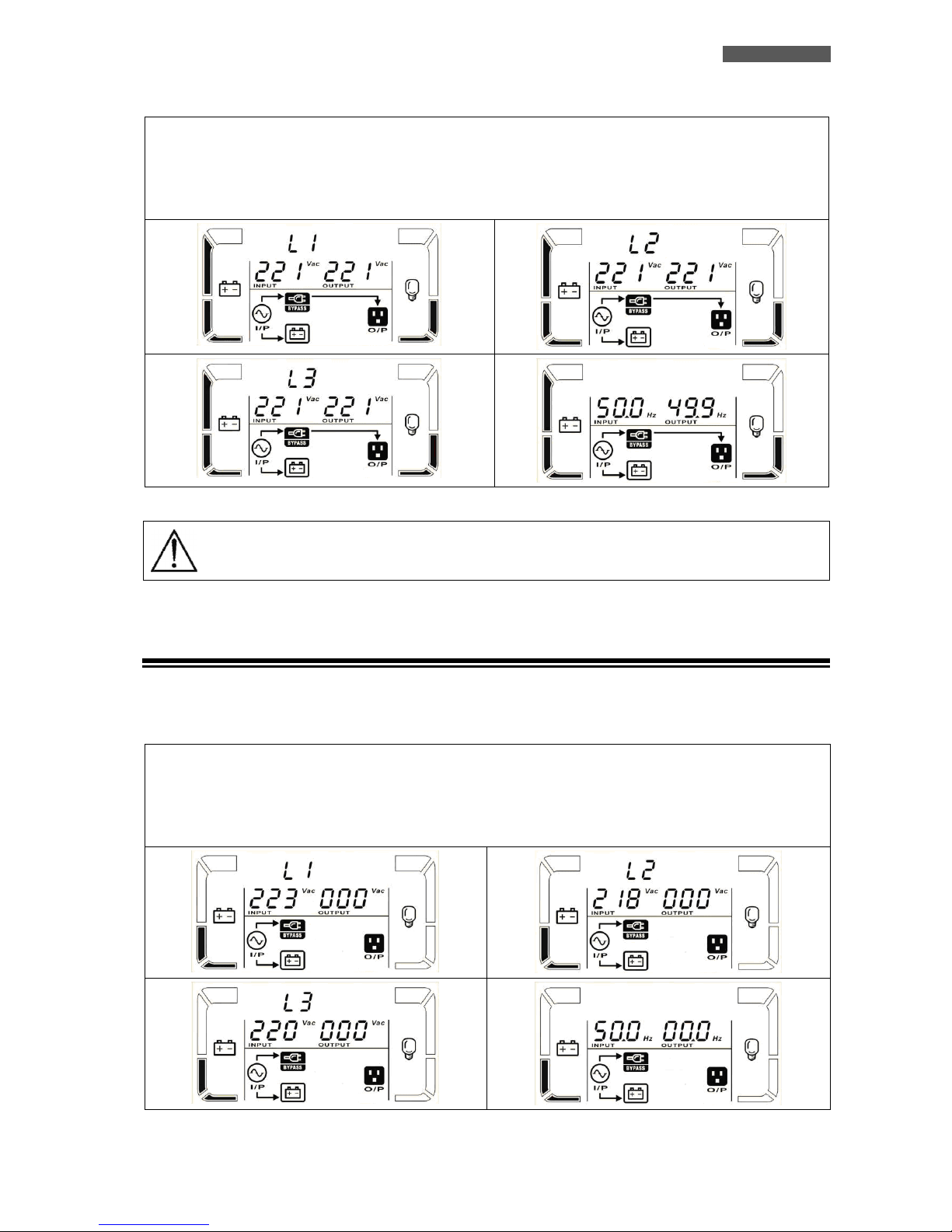
4.5 NO-OUTPUT Mode
When Bypass voltage/frequency is out of acceptable range or Bypass is disabled, UPS will enter into No-Output
mode if powering on or turning off the UPS. It means the UPS has no output.
The No-Output mode is identified by:
1. All he leds are OFF.
2. The graphic LCD panel shows the path of energy flow during No-Output mode.
3. An acoustic signal every 2 minutes.
ENGLISH
User’s manual 8 UPS EVO DSP PLUS TM
4.6 BATTERY TEST mode
When UPS is in AC mode or CVCF mode, press “Test” key for more than 0.5s. Then, the UPS will beep once and
start the Battery Test mode. The line between I/P and inverter icons will blink to remind users. This operation is
used to check the battery status.
The Battery Test mode is identified by:
1. Battery, Line and Bypass leds are ON.
2. The graphic LCD panel shows the path of energy flow during Battery Test mode.
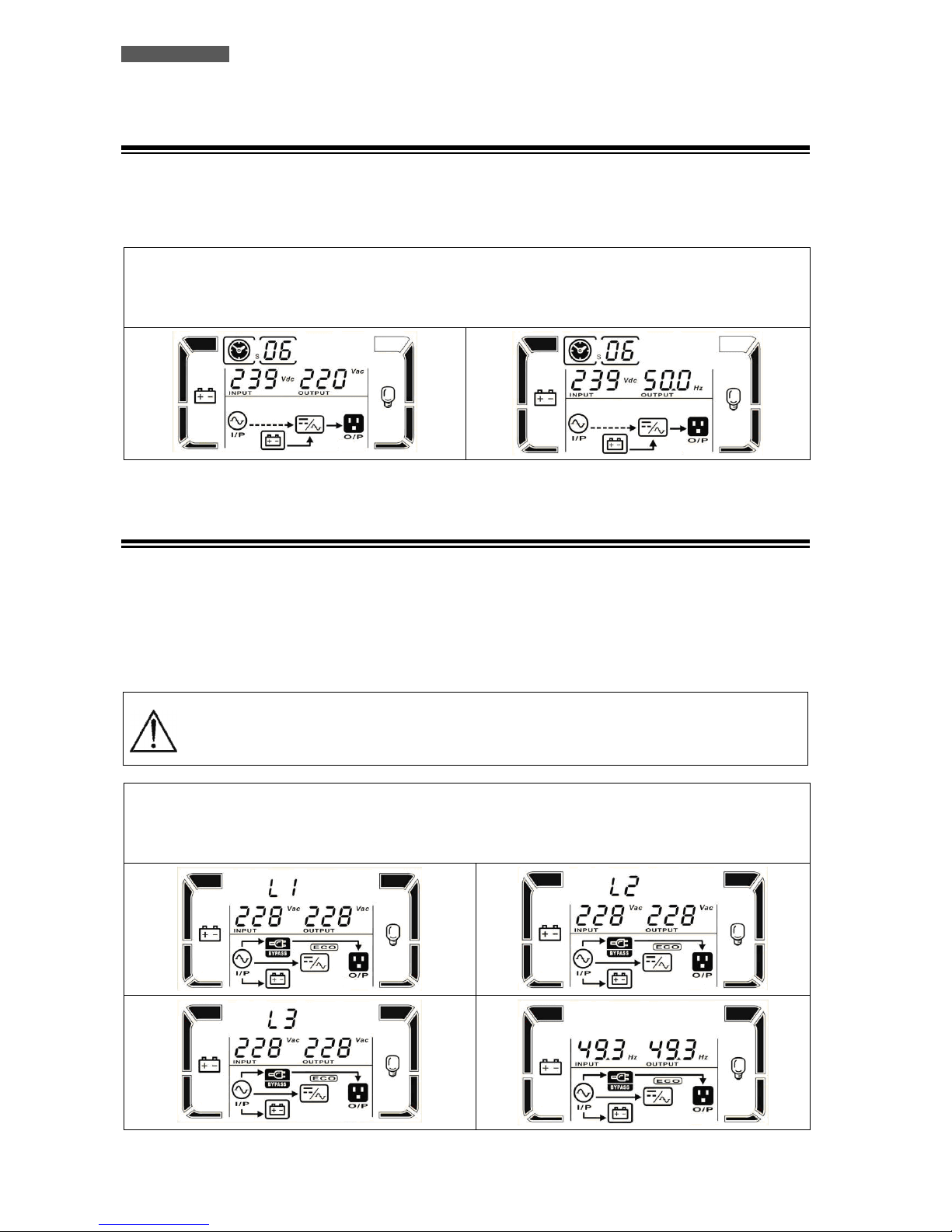
4.7 ECO Mode
It is possible to select the ECO mode to save energy and to increase the efficiency of the UPS.
The ECO mode uses the Bypass to feed the loads. The UPS will operate as in Bypass mode whenever the
Frequency/waveform/RMS value of AC Input line mains Voltage is within their tolerance limits. If the AC Input line
Voltage goes beyond these limits, the UPS switches into normal operation.
Please contact Technical Service for the instruction to enable the ECO mode; by default ECO mode is disable.
ECO mode does not provide perfect stability in Frequency/waveform/RMS value of the
Output Voltage like in Normal mode. Thus, the use of this mode should be carefully
executed according to the level of protection required by the application.
The ECO mode is identified by:
1. Bypass and Line leds are ON.
2. The graphic LCD panel shows the path of energy flow during ECO mode (the “ECO” icon is ON).
ENGLISH
UPS EVO DSP PLUS TM 9 User’s manual
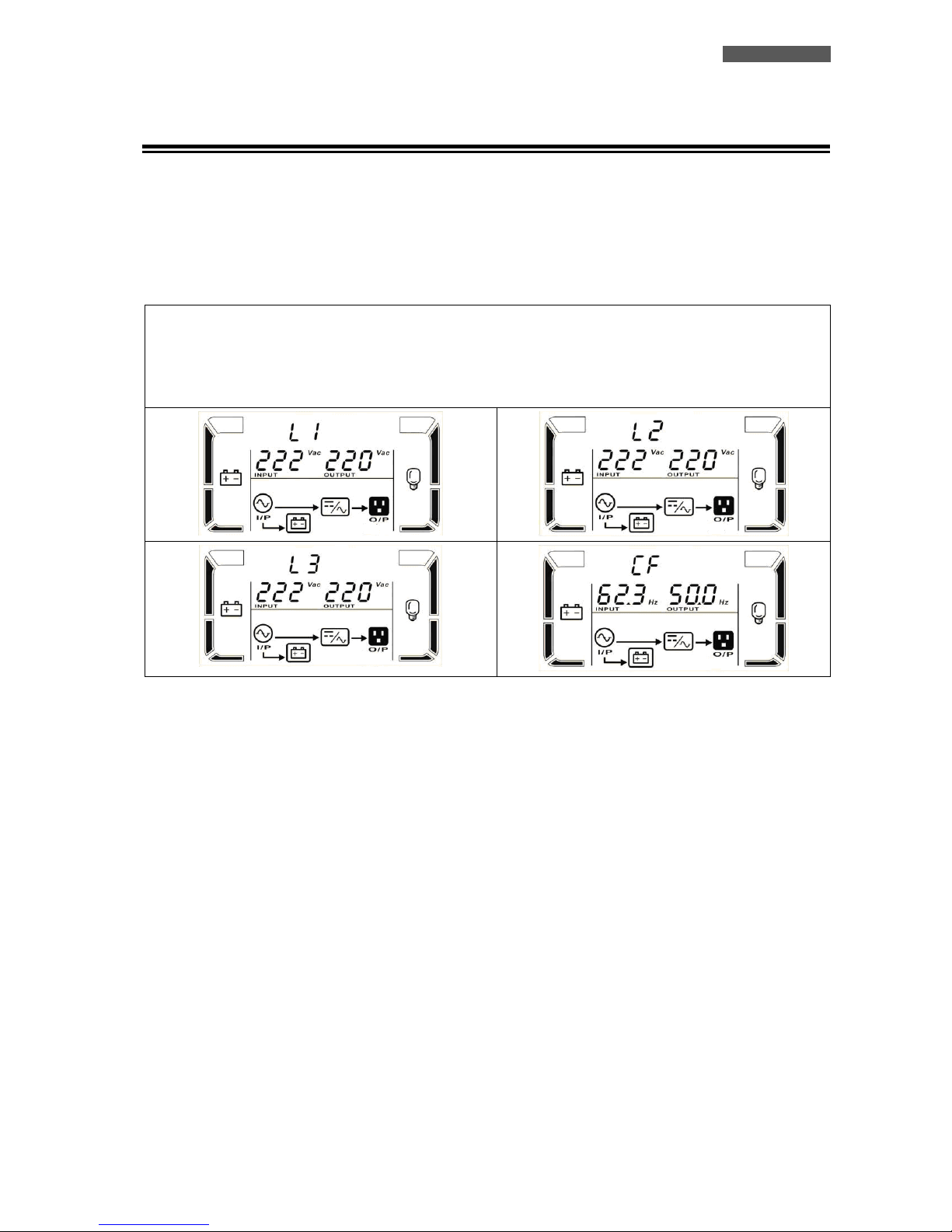
4.8 CONVERTER FREQUENCY Mode
It is possible to select the Converter Frequency mode to work with the Output Frequency different from the Input
Frequency. For example it is possible to work with 60 Hz Input Frequency and 50 Hz Output Frequency or 50Hz
Input Frequency and 60 Hz Output Frequency.
Please contact Technical Service for the instruction to enable the Converter Frequency mode; by default
Converter Frequency mode is disable, and the Output Frequency will synchronize automatically with the Input
Frequency.
The Converter Frequency mode is identified by:
1. Line led is ON.
2. The graphic LCD panel shows the path of energy flow during Converter Frequency mode.
3. The “CF” characters are ON together with the Input/Output frequency.
ENGLISH
User’s manual 10 UPS EVO DSP PLUS TM
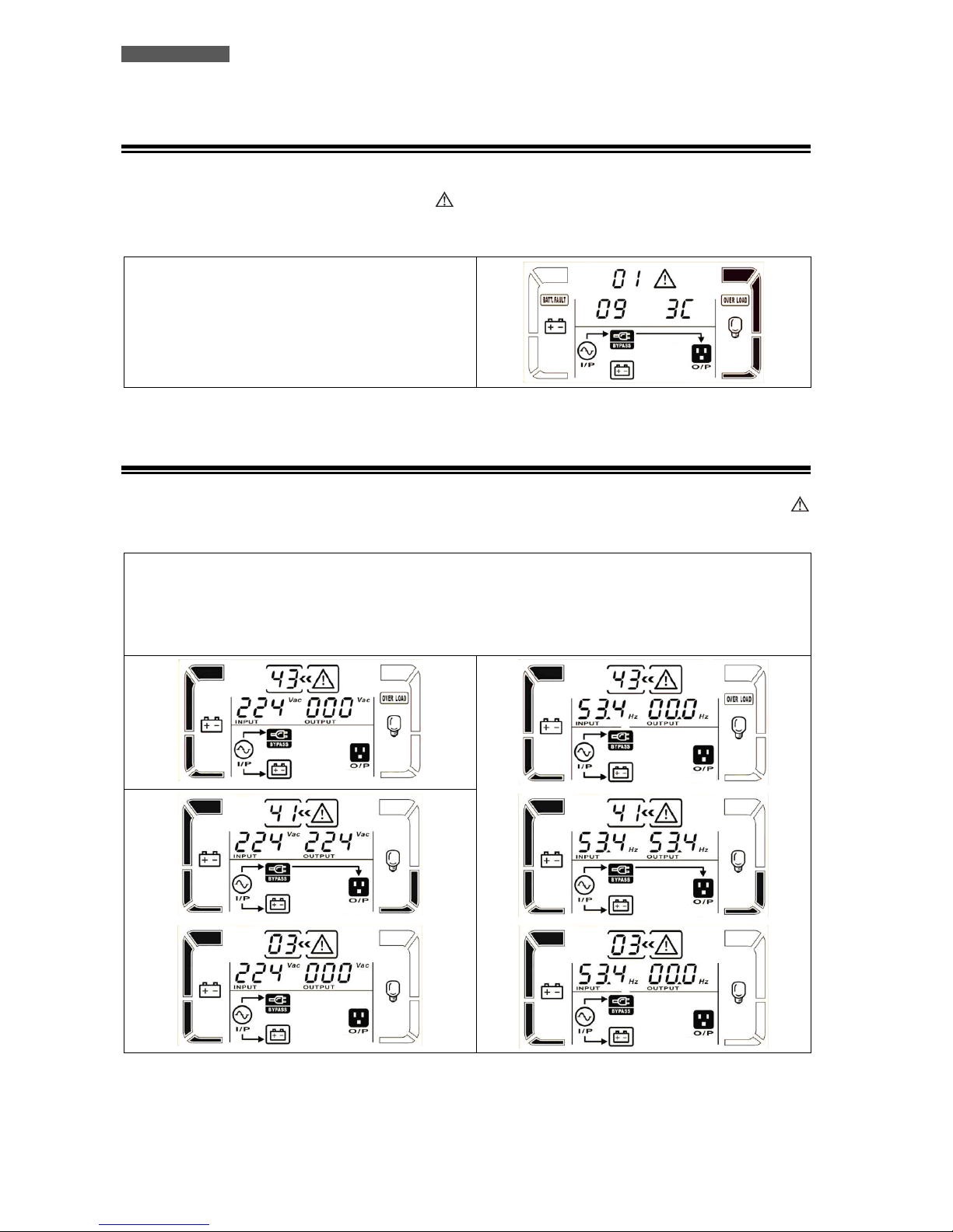
4.9 WARNING STATUS
If some errors occur in the UPS (but it is still running normally), it will show one more screen to represent the
warning situation. In the warning screen, the icon will be flashing, and it can show up to 3 error codes and
each code indicates one error. You can find the code meaning in the warning code table (see 8.6 chapter).
The Warning Status is identified by:
1. Line led is ON.
2. The graphic LCD panel shows the path of energy flow
during Warning Status.
3. An acoustic signal every second.
4.10 FAULT STATUS
When UPS has fault happened, the inverter will be blocked. It will display Fault code in screen, and the icon
will light up. You can find the code meaning in the Fault code table (see 8.7 chapter).
The Fault Status is identified by:
1. Fault led is ON.
2. The graphic LCD panel shows the path of energy flow during Fault Status.
3. A continuous acoustic signal.
ENGLISH
UPS EVO DSP PLUS TM 11 User’s manual
5 External Description
5.1 Front Panel
The front panel informs the user about operating status, alarm conditions and measurements. It also provides
access to controls and configuration parameters.
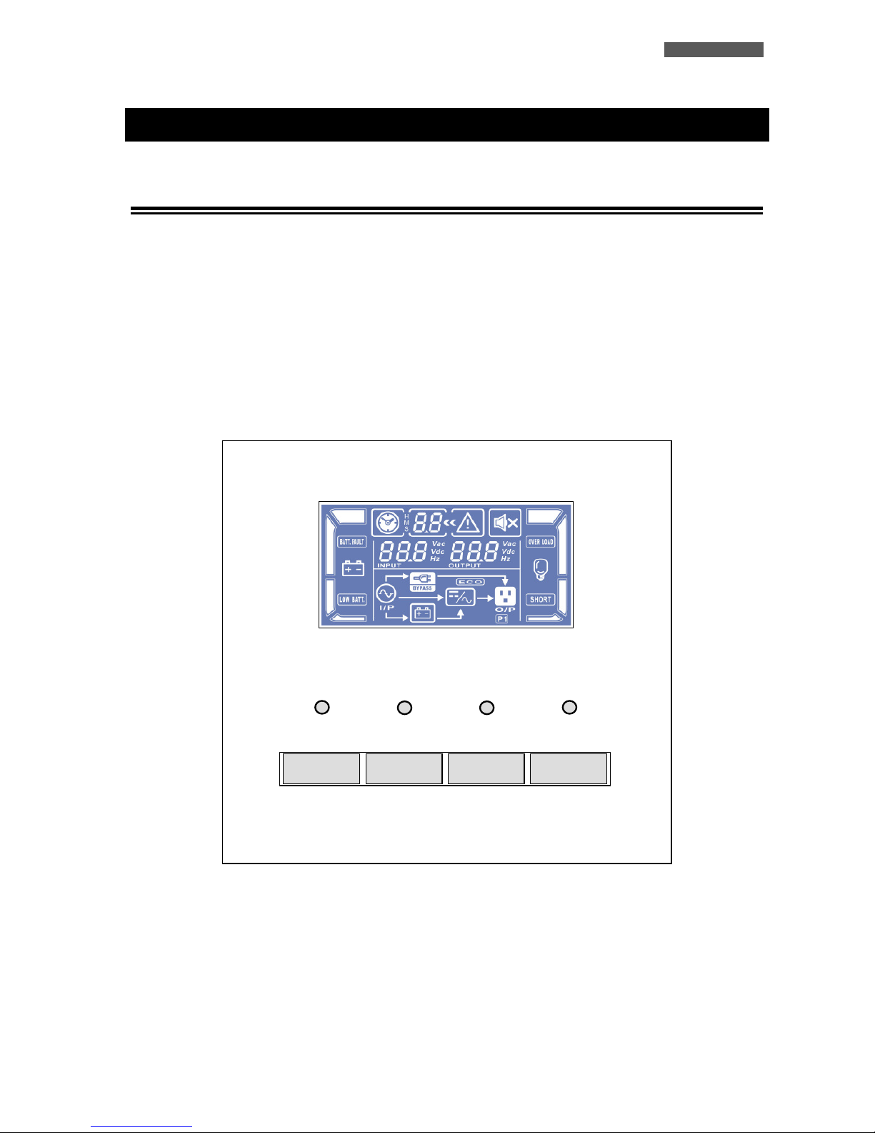
Front panel shown below consists of three parts:
1. Graphic LCD panel provides complete information about the energy flow path and existing alarms, Load and
Battery level, Input, Output and Battery measurements.
2. 4 LEDs when illuminated indicate UPS status.
3. 4 buttons enable the user to turn ON/OFF the UPS and to make selections of the functioning parameters.
Figure 2 – Front panel
Bypass
Line
Battery
Fault
OFF
TEST
MUTE
ON
ENGLISH
User’s manual 12 UPS EVO DSP PLUS TM
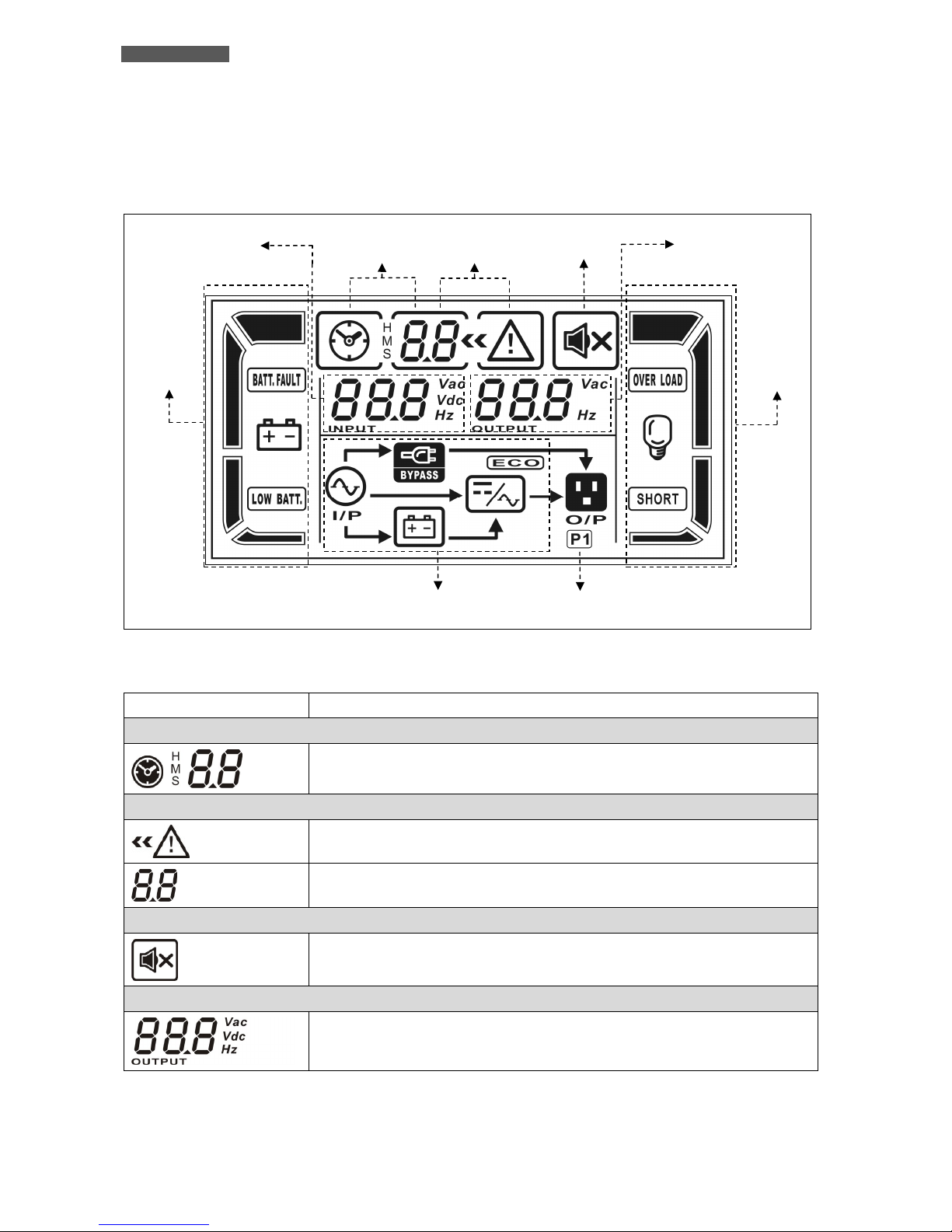
5.1.1 Graphic LCD Panel
Please refer to figure 3.
Figure 3 – Graphic LCD Panel
Graphic LCD Panel Function
Backup time information
Indicates how much time has passed in Battery mode.
H: hours, M: minutes, S: seconds
Fault information
Indicates the warning that a fault has occurred.
Indicates the Fault codes, and the codes are listed in the “Fault Table” of chapter
8.
Mute operation
Indicates that the UPS alarm is disabled (muted).
Output Voltage information
Indicates the Output Voltage or Frequency.
Vac: Output Voltage - Hz: Output Frequency
Battery
Info
Mode Operation
Info
Input & Battery
Voltage Info
Output
Voltage Info
Load
Info
Backup Time
Info
Fault Info Buzzer Info
Programmable
Output
Info
ENGLISH
UPS EVO DSP PLUS TM 13 User’s manual
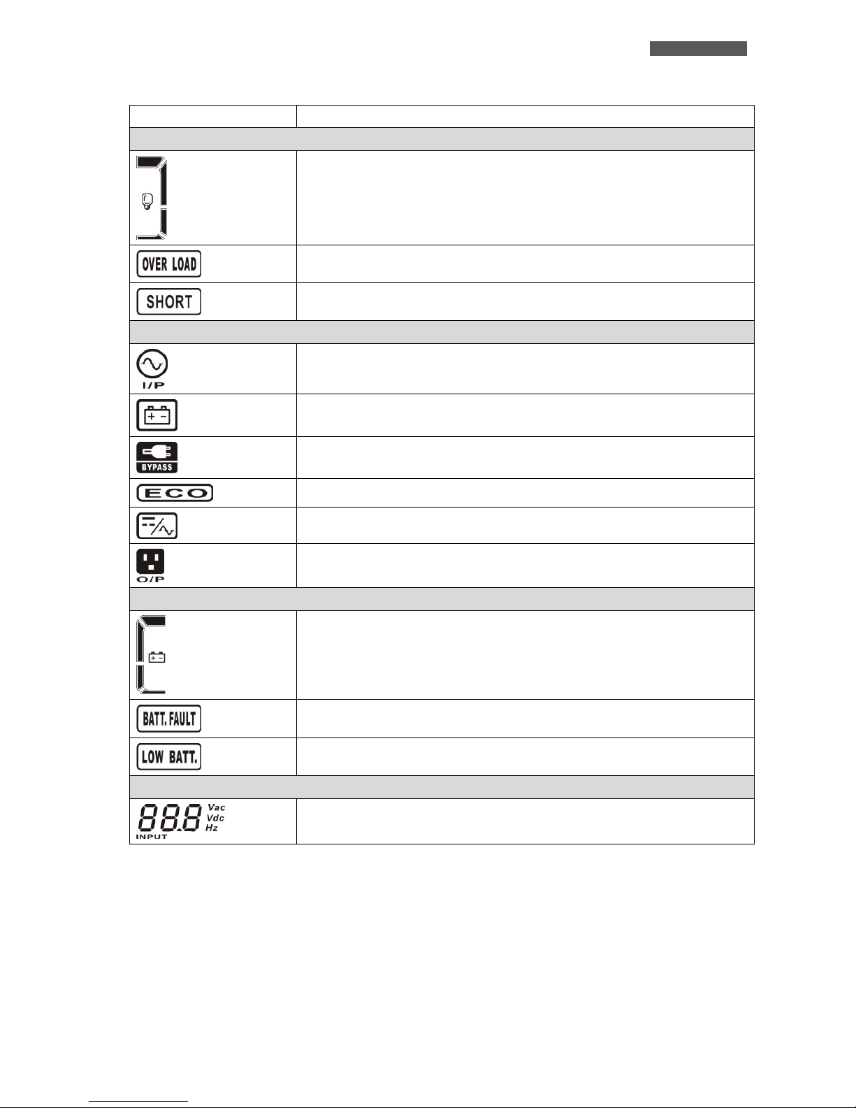
Graphic LCD Panel Function
Load information
Indicates the load level by 0-25%, 26-50%, 51-75%, and 76-100%.
Indicates Overload.
Indicates the load or the Output is short-circuited
Mode operation information
Indicates the UPS connects to the mains.
Indicates the Battery is working.
Indicates the Bypass circuit is working.
Indicates the ECO mode is enabled.
Indicates the Inverter circuit is working.
Indicates the Output is working.
Battery information
Indicates the Battery capacity by 0-25%, 26-50%, 51-75%, and 76-100%.
Indicates the Battery is faulty or defective.
Indicates Low Battery level and Low Battery Voltage.
Input and Battery Voltage information
Indicates the Input Voltage or Frequency or Battery Voltage.
Vac: Input Voltage - Vdc: Battery Voltage - Hz: Input Frequency
ENGLISH
User’s manual 14 UPS EVO DSP PLUS TM
5.1.2 Buttons
Functions of the buttons are given below:
Button Function
ON Turn ON: press and hold the button more than 0.5 sec to turn the UPS ON.
OFF Turn OFF: press and hold the button more than 0.5 sec to turn the UPS OFF.
TEST
Battery Test: press and hold the button more than 0.5 sec to test the Battery while in Normal
mode.
MUTE
Mute the alarm: press and hold the button more than 0.5 sec to mute the buzzer. If you press it
again after the buzzer is muted, the buzzer will beep again.
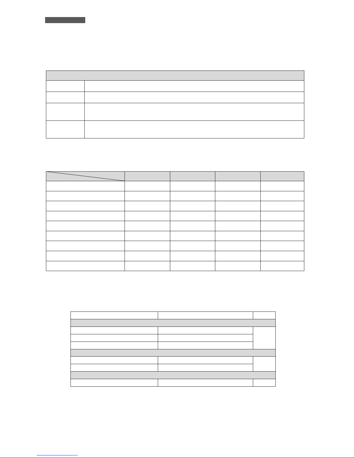
5.1.3 LED Indicators
There are 4 LEDs on the front panel to show the UPS working status:
Status LED Bypass Line Battery Fault
UPS Power On
● ● ● ●
NORMAL Mode
○ ● ○ ○
BATTERY Mode
○ ○ ● ○
BYPASS Mode
● ○ ○ ○
NO-OUTPUT Mode
○ ○ ○ ○
BATTERY TEST Mode
● ● ● ○
ECO Mode
● ● ○ ○
FREQUENCY CONVERTER Mode
○ ● ○ ○
FAULT Status
○ ○ ○ ●
Note: ● means LED is lit (ON) and ○ means LED is not lit (OFF).
5.1.4 Acoustic Alarm
Description Buzzer Status OFF
UPS status
Bypass Mode Beeping once every 2 minutes
YES Battery Mode Beeping once every 4 seconds
Fault Mode Beeping continuously
Warning
Overload Beeping twice every second
NO
Others Beeping once every second
Fault
All Beeping continuously YES
Note: OFF = YES means that the buzzer can be muted or stopped
OFF = NO means that the buzzer can NOT be muted or stopped

ENGLISH
UPS EVO DSP PLUS TM 15 User’s manual
5.2 Rear Side
Figure 4 – Rear side (on the left: EVO DSP PLUS TM 10 KVA; on the right: EVO DSP PLUS TM 15/20 KVA)
1
3
6
5
4
3
2
1
7
8
9
10
11
1
3
6
8
9
10
11
12
543
2
1
7
11
12
13

ENGLISH
User’s manual 16 UPS EVO DSP PLUS TM
1. Computer Interface (DB9 female connector): it is the communication RS-232 port.
2. Computer Interface (USB connector): it is the communication USB port.
3. EPO (Emergency Power OFF) connector
4. Share Current port (only available for Parallel model)
5. Parallel ports (only available for Parallel model)
6. Slot for SNMP Interface (optional)
7. Power stage fans
8. External Battery Box connector
9. Metallic panel for access to the Input/Output terminals: upon removal, it is possible to access the
Input/Output terminals (see figure 5).
10. Line Input circuit breaker
11. Maintenance Bypass switch
12. Output Circuit Breaker (10A max Current): it goes off in overload or short-circuit condition; push the
external button of the Circuit Breaker to reactivate it.
13. Grounded Output socket (IEC C13 type, 10A Max Current, 250 Vac): for connecting equipments to be
protected.
5.2.1 Input/Output Terminals
Figure 5 –
Input/Output Terminals
INPUT terminals: to connect AC Input line
OUTPUT1 terminals: to connect OUTPUT1 line
OUTPUT2 terminals: to connect OUTPUT2 line
BATTERY terminals: use only to connect an external Battery Box
GND: GROUND screws to connect INPUT, OUTPUT and external Battery Box GROUND cables
ENGLISH
UPS EVO DSP PLUS TM 17 User’s manual
OUTPUT1 is a NON PROGRAMMABLE Output: please connect all the critical devices to
OUTPUT1.
Instead OUTPUT2 is a PROGRAMMABLE Output: please connect ONLY the non-critical
devices to OUTPUT2.
During power failure, you may extend the backup time to critical devices by setting
shorter backup time for non-critical devices.
As default OUTPUT2 is NOT programmed.
In the case you need to program OUTPUT2 please consult Tecnoware Service for the instruction.
5.2.2 EPO (Emergency Power Off)
EVO DSP PLUS TM models have the EPO (Emergency Power OFF) connector on the rear side, (see figure 6).
This permits to immediately switch the UPS Output OFF from a distance in case of emergency.
The UPS is supplied with EPO short-circuited terminals and in this case the product works normally.
If you want to use an external switch to turn OFF the UPS by EPO, then remove the short-circuit from the EPO
terminals and connect the switch to the EPO terminals as described in the figure 6.
EPO
1
2
REMOTE EPO
SWITCH
Figure 6 – EPO (Emergency Power OFF)
If the switch is CLOSED the UPS works normally; if, on the contrary, the switch becomes
OPEN then the UPS Output turns OFF immediately.
To switch the UPS Output ON again after an EPO, it is necessary to close again the EPO switch.
The EPO terminals are isolated and do not need an external feeding Voltage.
6 Electrical Installation
The electrical installation has to be done by qualified personnel. Follow all the Safety
Standards (CEI Standards in Italy or IEEE elsewhere) for the Input/Output connections
and for the right selection of Input/Output cables.
We recommend to use dedicate AC Input/Output power lines for the UPS.
For safety we recommend using external circuit breakers between Input mains and UPS
AC Input line and between UPS Output lines and the loads. The circuit breakers should
be qualified with leakage current protective function (leakage current < 30 mA).
ENGLISH
User’s manual 18 UPS EVO DSP PLUS TM
EVO DSP PLUS TM models are made of a single unit design that contains the electronic parts and batteries.
Before starting the installation procedure, be sure that:
1. The Input circuit breaker on the rear panel is “OFF” (see figure 4).
2. The AC Input Voltage for the UPS has been removed.
3. The UPS is completely OFF (only if graphic LCD panel is OFF).
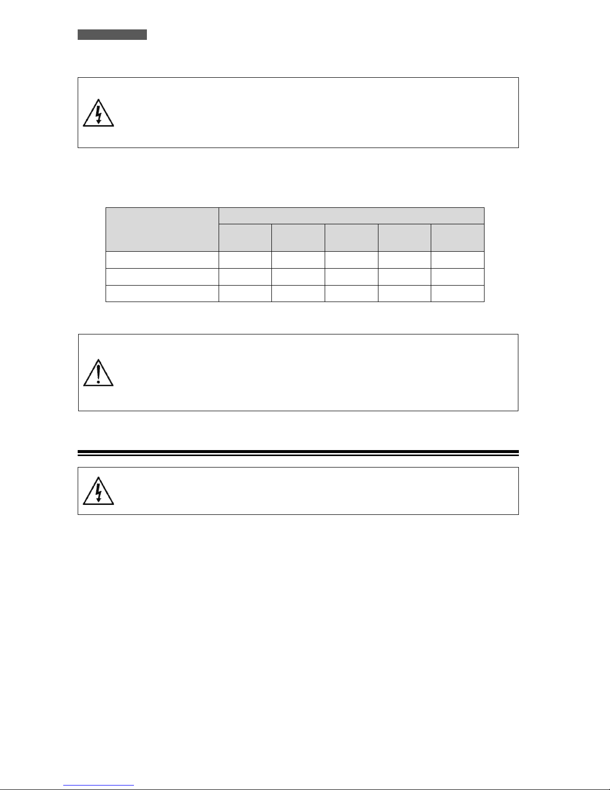
The following table shows the recommended size for Input, Output and Battery wires.
Model
Wiring spec (cross section)
Input
Phases
Output
Phases
Neutral Battery Ground
EVO DSP PLUS TM 10KVA 10 mm2 10 mm2 10 mm2 10 mm2 10 mm2
EVO DSP PLUS TM 15KVA 16 mm2 16 mm2 16 mm2 16 mm2 16 mm2
EVO DSP PLUS TM 20KVA 16 mm2 16 mm2 16 mm2 16 mm2 16 mm2
ATTENTION: for safety and efficiency it is recommended to use always cables with the
cross section equal or thicker than the specified one into the previous table.
We recommend using only flexible TRI-RATED cables. Otherwise if you use rigid cables,
it will be difficult to move the UPS from initial positioning.
We recommend to use dedicate AC Input/Output power Lines for the UPS.
6.1 Installation
Connect the GROUND wire first when making wire connection. Disconnect the GROUND
wire last when making wire disconnection.
Make sure that the wires are connected tightly to the terminals.
We advise you to follow the steps below explained:
1. Remove the metallic panel that covers the Input/Output terminals, see figure 4. The terminals are shown in
figure 5. All the cables have to reach the terminals from the rear side using the proper holes in the metallic
panel.
2. Connect the INPUT line paying attention to the right polarity, in accordance with figure 5, as explained
below:
Connect INPUT GROUND wire to the INPUT GND screw.
Connect INPUT LINE L1 phase wire to the INPUT L1 terminal (#3).
Connect INPUT LINE L2 phase wire to the INPUT L2 terminal (#4).
Connect INPUT LINE L3 phase wire to the INPUT L3 terminal (#5).
Connect INPUT NEUTRAL wire to the INPUT N terminal (#6).
3. Connect the OUTPUT line paying attention to the right polarity, in accordance with figure 5, as explained
below:
4. Connect the OUTPUT1 line (LINE, NEUTRAL and GROUND) as follow:
 Loading...