

Tecnoware EVO 1.0 RT, EVO 2.0 RT, EVO 3.0 RT User Manual
EVO RT
Uninterruptible Power Supply
EVO 1.0 RT
EVO 2.0 RT
EVO 3.0 RT
USER’S MANUAL
MANUALE UTENTE


11 INDEX - INDICE
USER’S MANUAL (ENGLISH)
SECURITY NOTICE.........................................................................page 3
INTRODUCTION ............................................................................page 3
1 MAIN CHARACTERISTICS ...............................................................page 4
2 EXTERNAL DESCRIPTION................................................................page 5
3 RUNNING OPERATIONS..................................................................page 9
4 INSTALLATION INSTRUCTIONS .......................................................page 12
5 COMPUTER INTERFACE ..................................................................page 13
6 TECHNICAL CHARACTERISTICS.......................................................page 14
7 SUGGESTIONS FOR A CORRECT USE ...............................................page 15
8 ANOMALIES AND TROUBLESHOOTING..............................................page 17
9 FIGURES......................................................................................page 18
...........................................................page 2
MANUALE UTENTE (ITALIANO)
AVVISI DI SICUREZZA...................................................................pag. 22
INTRODUZIONE ............................................................................pag. 23
1 CARATTERISTICHE GENERALI.........................................................pag. 24
2 DESCRIZIONE ESTERNA.................................................................pag. 25
3 FUNZIONAMENTO..........................................................................pag. 29
4 NORME D'INSTALLAZIONE..............................................................pag. 32
5 INTERFACCIAMENTO......................................................................pag. 33
6 CARATTERISTICHE TECNICHE.........................................................pag. 34
7 CONSIGLI PER UN CORRETTO UTILIZZO...........................................pag. 35
8 ANOMALIE E INTERVENTI ..............................................................pag. 37
9 FIGURE........................................................................................pag. 38
......................................................pag. 22
Copyright 2007 TECNOWARE s.r.l. All rights reserved.
©
All trademark are property of their respective owners.
TECNOWARE s.r.l.
www.service.tecnoware.com
This manual has been printed and edited by TECNOWARE s.r.l.
March 2007 Edition version 1.0

ENGLISH
USER’S MANUAL – ENGLISH
11 SECURITY NOTICE
Read this manual carefully before installing and using TECNOWARE EVO RT
Uninterruptible Power Supply, which will be referred to as UPS from hereafter.
The UPS must be used only by properly trained personnel. To ensure correct and
safe operation, it is necessary that operators and maintenance personnel observe
the general Safety Standards as well as the specific instructions included in this
manual.
Risk of electric shock: do not remove the cover. The UPS contains internal parts
which are at a high voltage and are potentially dangerous, capable of causing injury
or death by electric shock.
There are no internal parts in the UPS that can be repaired by the user. Any repair or
maintenance must be performed exclusively by qualified technical personnel
authorized by TECNOWARE. TECNOWARE declines any responsibility if this warning
is disregarded.
It is compulsory to ground the UPS according to Safety Standards.
Risk of electric shock at the output socket when the UPS is ON.
Risk of electric shock at the output socket while the unit is connected to the AC
utility line.
Use the input power cable given with the unit and connect it to the AC utility line. In
all circumstances a (H05VVF3G 1,5mm²) cable or a better one must be used.
Do not obstruct ventilation slots or holes and do not place any object on top of UPS.
Do not insert objects or pour liquids in the ventilation holes.
Do not keep liquids, flammable gases or corrosive substances near the UPS.
Install the UPS indoors, in a protected, clean and moisture-free environment.
UPS EVO RT 2 User’s manual

ENGLISH
11 INTRODUCTION
UPS EVO RT
UPS EVO RT (Uninterruptible Power Supplies) are the result of constant technological research
aimed at obtaining the best performance at the lowest cost.
UPS EVO RT are advanced ON-LINE UPS, single-phase, built specifically to protect your
computer from any irregularities in the AC line (for example blackouts, brownouts,
overvoltages, micro-interruptions) which often cause damage to hardware and software.
During a power failure, EVO RT continues supplying adequate AC power (with a true sinewave)
to all connected devices by its internal battery and by its DC/AC converter (Inverter).
Under normal AC line condition, EVO RT provides an automatic output voltage regulation by the
Rectifier and Inverter blocks and filters out frequently occurring electrical disturbances (high
voltage transients, spikes, interferences, etc.), thus protecting the devices connected to its
outlets.
EVO RT protects the devices from accidental overload or Inverter fault by an AUTOMATIC
BYPASS that directly connects the AC input line with its outlets.
EVO RT is supplied with an RS-232 communication port and USB port, which can be used to
signal to a generic processor or computer the absence of mains condition or the end of
autonomy condition. This permits to carry out an automatic data saving operation duri ng a long
black out with the most spread Operating Systems (Windows, Linux, Novell, etc).
Furthermore, the communication ports permit EVO RT to communicate with the computer,
transferring various measurements such as: input output voltage, battery voltage, output
power, frequency, and can also be programmed for automatic operations such as switching
ON/OFF in a preset time.
WARNING
Please read this manual before using EVO RT, because it contains important safety
information for the operator in order to carry out a correct use of the unit.
This manual is related to the below EVO RT models:
• EVO 1.0 RT
• EVO 2.0 RT
• EVO 3.0 RT
EVO RT is in 19” RACK version; it means that its sizes are compatible with 19” RACK cabinets
and it has been designed to be included in the 19” RACK cabinets
EVO can even be used in TOWER position that is a vertical one, thanks to the relative and
reliable pedestals
EVO RT is constantly being developed and improved: consequently, your unit may differ
somewhat from the description contained in this manual.
In this manual, the same for all 3 models, EVO RT will simply be called UPS.
User’s manual 3 UPS EVO RT

ENGLISH
11 MAIN CHARACTERISTICS
EVO RT offers all the modern characteristics which guarantee maximum reliability and security:
• Microprocessor control guarantees high reliability
• ON-LINE double technology without transformer
• Pure Sinewave
• Output voltage regulation +/- 2%
• Overload, overheating and short circuit protection
• AUTOMATIC BYPASS to protect from accidental overload or Inverter fault
• MANUAL BYPASS through switch on the rear side
• Switching ON even with no mains condition
• Automatic protection in case of discharged batteries
• After a shutdown caused by the end of autonomy and when mai ns condi ti on is restored there
is an automatic SWITCHING On operation
• Automatic functioning test through a switch
• Automatic regulation to the input frequency 50 or 60 Hz
• Visual warnings by leds, indicating operational mode and low battery, overload and alarm
conditions
• Dry Contact board (optional)
• SNMP Adapter (optional)
• EPO (Emergency Power OFF)
• Remote ON/OFF
• Acoustic signals of various kinds indicating alarm situations
• Communication with the computer by a RS-232 Interface and possible monitoring of
input/output voltage, frequency, output power, battery voltage, etc.
• Automatic turn on/off user-programmable by RS-232 Interface
• Protection filter for the telephone, ADSL and data l ine
• Possibility to increase the autonomy through External Battery boxes (optional)
• HOT SWAP BATTERY
• Sizes compatible with 19” RACK cabinets
• Can be used in TOWER position that is a vertical one, thanks to the provided pedestals
• High reliability and high performances
• Easy to use
UPS EVO RT 4 User’s manual

ENGLISH
12 EXTERNAL DESCRIPTION
FRONT PANEL
On the front panel there are the control buttons and some leds which indicate the various
operating mode and alarm conditions. Please see the figures 1 and 2
ON/TEST/ALARM button
Can be used for 3 functions:
• TURN ON: the UPS is turned on by keeping the button continuously pressed for more than 3
seconds.
• SELF-TEST: the UPS performs a SELF-TEST, according to the procedure explained further on,
when the button is pressed during LINE mode for more than 3 seconds.
• ALARM OFF: during BATTERY mode, to disable the alarm buzzer, press this button for more
than 3 seconds.
OFF button
To turn off the UPS, press this button for more than 3 seconds.
LINE led
This led (blue) is ON when the input AC line voltage amplitude is within the specification, and it
indicates the UPS is working in LINE mode.
If LINE led flashes every second it shows that Phase line and Neutral line of AC input utility line
are inverted. In that case it must disconnected the AC power input pl ug from power receptacle,
turn it at 180 degrees and plug in the power receptacle again.
INVERTER led
This led (blue) is on when the Inverter is regularly working
BATTERY led
This led (blue) is on when the UPS is working in BATTERY mode (during a blackout or
overvoltage/brownout).
BYPASS led
This led (blue) is on when the UPS is working in BYPASS mode: the AC input line is connected
directly with the UPS outlets.
FAULT led
This led (red) is turned on whenever the UPS detects a FAULT condition and needs a technical
intervention as soon as possible.
User’s manual 5 UPS EVO RT

ENGLISH
LOAD LEVEL led bar
The led bar has 6 leds (5 leds are bl ue and one led is red). This bar indicates the output power
percentage (LOAD LEVEL), proportional to the number of switched on leds. The greater the load
the more LED indicators will light on.
There are the following LOAD LEVEL percentages:
• 0~20%: only one led is on (LED13)
• 21~40%: two leds are on (LED13 and LED12)
• 41~60%: three leds are on (LED13, LED12 and LED11)
• 61~80%: four leds are on (LED13, LED12, LED11 and LED10)
• 81~100%: five leds are on (LED13, LED12, LED11, LED10 and LED 9)
The OVERLOAD red led (LED8), is on to warn of an OVERLOAD condition.
BAT. LEVEL led bar
The led bar has 6 leds (5 leds are blue and one led is yellow). This bar in dicates the battery
capacity percentage (BAT. LEVEL), proportional to the number of switched on leds. The higher
the battery capacity the more LED indicators will light on.
There are the following battery capacity percentages:
• 100~81%: five leds are on (LED15, LED16, LED17, LED18 and LED19)
• 80~61%: four leds are on (LED15, LED16, LED17 and LED18)
• 60~41%: three leds are on (LED15, LED16 and LED17)
• 40~21%: two leds are on (LED15 and LED16)
• 20~0%: only one led is on (LED15)
The LOW BAT yellow led (LED14), is on to warn of a LOW BATTERY condition during BATTERY
mode.
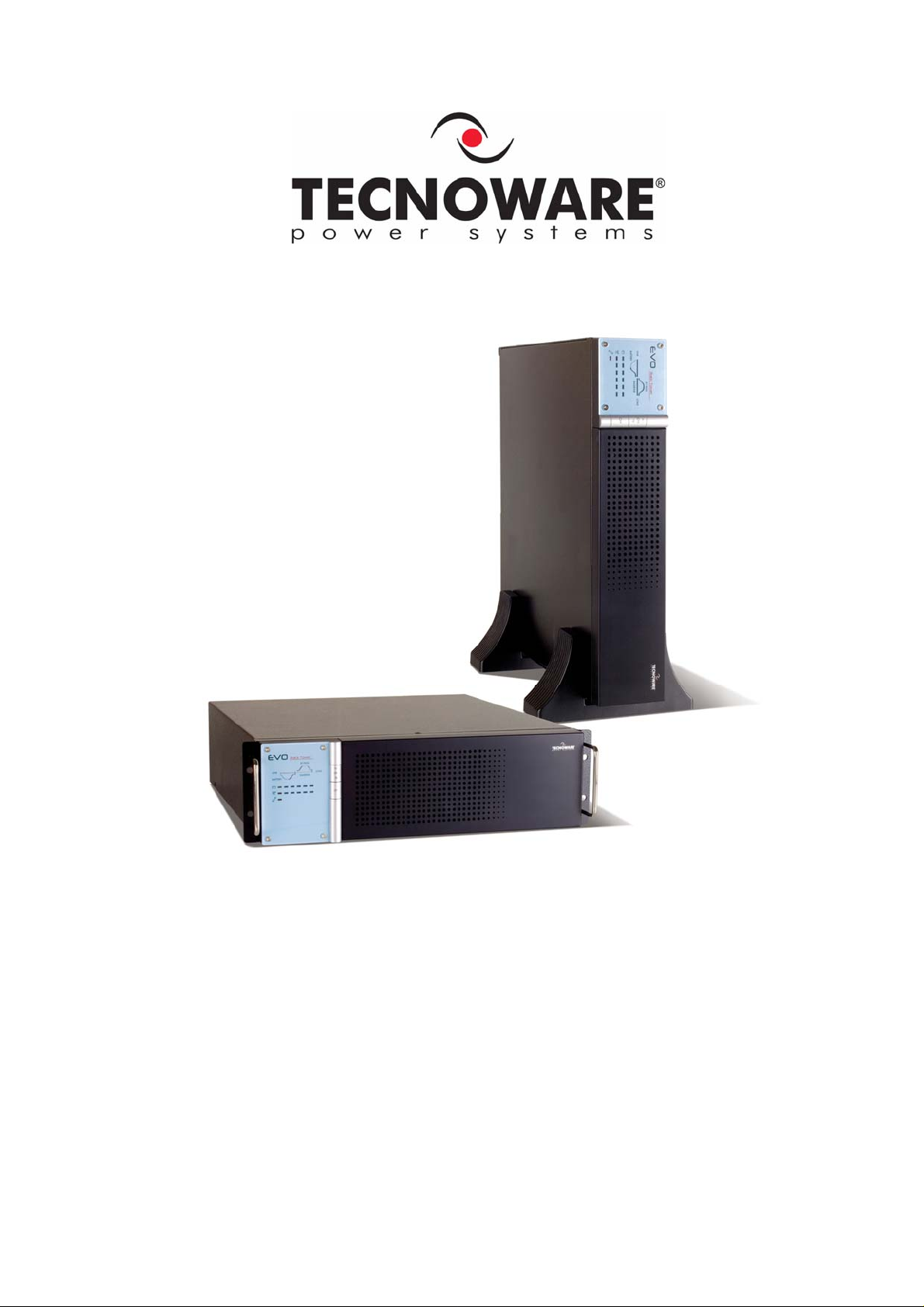
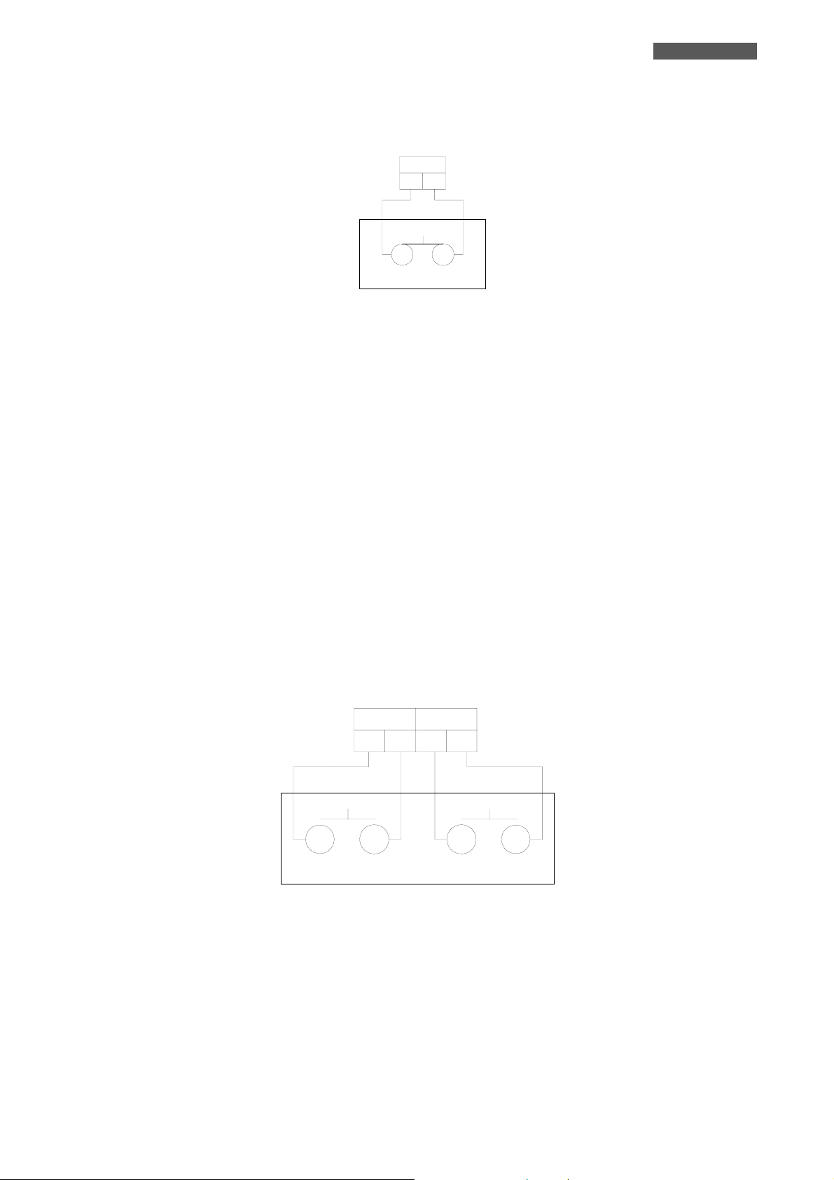
REAR SIDE
The following are located on the rear side (see figure 3):
1) Grounded AC Input power socket: to connect the UPS to AC utility line by the supplied
input cord.
2) Input Circuit Breaker: it goes off in overload or short-circuit condition; push the external
3) Grounded output socket: for connecting equipments to be protected.
4) (Only EVO 2.0 RT and EVO 3.0 RT) Grounded power output socket: for connecting
an output power line to supply all the equipments to be protected.
5) RS-232 Computer Interface (female connector 9 poles DB9): it is the interface port
(RS-232) to communicate with a computer.
6) RJ11/RJ45 IN/OUT plugs: to protect and filter a phone line, an ADSL or a LAN.
7) External batteries connector: to connect the UPS to an external Box Battery (optional).
8) Slot for Dry Contact Board (optional)/SNMP adapter (optional)
9) Manual BYPASS switch: to force the UPS into BYPASS mode (see chapter “Running
Operations”).
10) Remote ON/OFF connector.
11) EPO (Emergency Power OFF) connector.
UPS EVO RT 6 User’s manual
ENGLISH
EPO (EMERGENCY POWER OFF)
EPO
2
1
External Switch
EPO
The EVO RT models have the EPO (Emergency Power OFF) connector (see figure 3) on the rear.
This permits to immediately switch the UPS OFF from a distance in case of emergency.
EVO RT is supplied with EPO short-circuited terminals and in this case the product works
normally.
If you want to use an external switch to turn off by EPO, then remove the short-circuit from the
EPO terminals and connect the switch to the terminals.
ATTENTION
If the external switch is CLOSED the UPS works normally. As soon as the switch is
going to be opened then the UPS turns OFF immediately.
In EPO condition, the UPS turns on the FAULT and OVERLOAD leds and emits a
continuous acoustic alarm.
To switch ON the UPS again it is necessary to close the EPO switch and then manually restart
the UPS from the front panel.
The EPO terminals are isolated and do not need an external feeding voltage.
REMOTE ON/OFF
ON
1
Remote Switch
ON
EVO RT has remote ON/OFF terminals connector on the rear side (see figure 3), this permi ts to
switch the UPS ON and OFF from a distance. Using the ON/OFF external button (as described in
the above picture) the frontal panel button capacity can be used from a distance.
EVO RT is ON; pressing the OFF button connected to terminal 1 and 2 for at least 3 seconds,
EVO RT turns OFF.
EVO RT is OFF; pressing the ON button connected to terminal 3 and 4 for at least 3 seconds,
EVO RT turns ON.
The remote ON function is disabled when the UPS is off and the AC input line voltage
is not present.
OFF
2
4
3
Remote Switch
OFF
User’s manual 7 UPS EVO RT

ENGLISH
DRY CONTACTS BOARD (OPTIONAL)
Common
2
1
Fault
3
Bypass
4
5
AC fail
6
7
8
Low BAT
10
9
On the UPS rear side there is a slot for mounting the FREE CONTACTS Board (see figure 3, point
8). The FREE CONTACTS Board has 4 Relay contacts (open/closed) free of any vol tage, in order
to signal at a distance Fault, Bypass, AC fail and Low BAT conditions.
The electrical characteristics of the Relay contacts are: max voltage 250V, max current 7A.
The FREE CONTACTS Board has a 10 pins connector: below there is the description of the
open/closed contacts available on the pins, depending on the working condition.
1. Common
Pin 1 and Pin 2 are common pins.
2. Fault
Pin 3 is the normal-open output: When UPS works normally, Pin 3 and Pin 1-2 will be open,
when UPS is failed, Pin 3 and Pin 1-2 will be closed.
Pin 4 is normal-closed output: When UPS works normally, Pin 4 and Pin 1-2 will be closed, when
is failed, Pin 4 and Pin 1-2 will be open.
3. Bypass
Pin 5 is the normal-open output: When UPS works normally, Pin 5 and Pin 1-2 will be open,
when UPS works in bypass mode, Pin 5 and Pin 1-2 will be closed.
Pin 6 is normal-closed output: When UPS works normally, Pin 6 and Pin 1-2 will be closed, when
UPS works in bypass mode, Pin 6 and Pin 1-2 will be open.
4. AC fail
Pin 7 is the normal-open output: When UPS works normally, Pin 7 and Pin 1-2 will be open,
when UPS works in AC failure mode, Pin 7 and Pin 1-2 will be closed.
Pin 8 is normal-closed output: When UPS works normally, Pin 8 and Pin 1-2 will be closed, when
UPS works in AC failure mode, Pin 8 and Pin 1-2 will be open.
5. Low Bat
Pin 9 is the normal-open output: When UPS works normally, Pin 9 and Pin 1-2 will be open,
when UPS works in battery low voltage mode, Pin 9 and Pin 1-2 will be closed.
Pin 10 is normal-closed output: When UPS works normally, Pin 10 and Pin 1-2 will be closed,
when UPS works in battery low voltage mode, Pin 10 and Pin 1-2 will be open.
The Dry Contact board is OPTIONAL
UPS EVO RT 8 User’s manual

ENGLISH
13 RUNNING OPERATIONS
SWITCHING ON
If the UPS is switched off and connected to the electric line, the LINE Led in the front side is
switched on together with the BAT. LEVEL led bar showing batteries capacity level. In these
conditions UPS has the only function of recharging batteries and there is no power on the output
sockets (switched off output). If it is disconnected from the AC utility line, after some second
UPS is switched off completely.
The UPS is switched off and connected to the AC utility line (LINE Led and BAT. LEVEL bar are
switched on). In order to switch the UPS on, it is sufficient to press continuousl y for more than
3 seconds ON/TEST/ALARM button of the front panel till when the UPS emits a short acoustic
signal showing its own switching on. The UPS effectuates an initial operating SELF TEST (during
which the red FAULT and OVERLOAD leds are switched on), and then activates the power on the
output sockets and at the same time it switches on the BYPASS led and the LOAD LEVEL bar
(indicating output power percentage); it starts working in BYPASS mode. After some second the
BYPASS led is switched off and the INVERTER Led is switched on: all this indicates that UPS has
started working normally in LINE mode.
If the UPS is not connected to the AC utility line or if the AC utility line is not present due to a
blackout, the UPS turns on with a sequence similar to the one described above.
Even in this case it needs to press continuously for more than 3 seconds ON/TEST/ALARM
button, till when the UPS emits a short acoustic signal showing its own switching on. The UPS
immediately switches on BAT. LEVEL bar, then it effectuates an initial operating SELF TEST
(during which the red FAULT and OVERLOAD leds are switched on), it switches on BATTERY Led
and after some seconds it activates the power on the output sockets and at the same time it
switches on INVERTER led and LOAD LEVEL bar (indicating output power percentage); it starts
working normally in BATTERY mode.
The UPS automatically returns to function in LINE mode a few seconds after the AC utility line is
recovered.
To switch the UPS off, press the OFF button for more than 3 seconds, till when the UPS emits a
short acoustic signal showing its own switching off. The output is disabled and all devices
powered by the UPS are switched off. The INVERTER led is switched off and UPS effectuates
then an operating SELF TEST (during which the red FAULT and OVERLOAD leds are switched
on).
If UPS is connected to the AC utility line, LINE led and BAT. LEVEL led bar remain switched on.
In these conditions, UPS effectuates only batteries recharging function and there is no power on
the output sockets (switched off output).
If UPS is not connected with the AD utility line, after some seconds it is switched off completely.
LINE MODE
This is the typical running mode: the AC input line is present and the amplitude is within
specifications. The UPS filters the input line, performs an output voltage regulation by the
RECTIFIER, BOOSTER and INVERTER blocks and supplies power to all connected devices.
Besides, it recharges the batteries and keeps them in an ideal charge condition.
The LINE mode is characterized by:
• The LINE led and INVERTER led switched on.
• The LOAD LEVEL and BAT. LEVEL led bars switched on.
User’s manual 9 UPS EVO RT

ENGLISH
BATTERY MODE
The UPS automatically runs in BATTERY mode if the Mains Voltage amplitude gets out of
security limits (in case of a black-out or overvoltage-l owvoltage): in this case, the UPS supplies
the required output power by its internal battery and by the DC/DC CONVERTER, BOOSTER and
INVERTER blocks (see figure 1).
The UPS automatically returns to function in LINE mode a few seconds after the AC input line is
recovered.
The BATTERY mode is characterized by:
• An acoustic signal every 4 seconds indicates that the batteries are discharged. The acoustic
signal can be disconnected by pressing the ON/TEST/ALARM button.
• The INVERTER led and BATTERY led switched ON.
• The LOAD LEVEL and BAT. LEVEL led bars switched on.
BYPASS MODE
In BYPASS mode (see figure 1), the AC input line is directly connected with the UPS outlets by
an AUTOMATIC BYPASS.
EVO RT uses the BYPASS mode during the start-up phase; furthermore the UPS switches
automatically to BYPASS mode in consequence of accidental overload or Inverter fault thus
protecting the supplied devices.
The BYPASS mode is characterized by:
• The BYPASS led and LINE led switched on.
• The LOAD LEVEL and BAT. LEVEL led bars switched on.
The UPS can be transferred in BYPASS mode even through a manual operation.
First of all it must be sure that the UPS is working properly in LINE mode. On the rear side of
the product (see figure 3) it is positioned the manual BYPASS switch. If this switch is in
position ON (BYPASS), the UPS changes in BYPASS mode and indicates this condition with:
• The BYPASS led and LINE led switched on.
• All the LOAD LEVEL led bar switched on, the red OVERLOAD and FAULT Leds switched on.
• Continuous acoustic alarm.
The UPS starts working again normally if it moves the switch in OFF (NORMAL) position.
Acoustic alarm stops immediately and the UPS effectuates then an operati ng SELF TEST (during
which the red FAULT and OVERLOAD Leds are switched on). After some seconds more the
BYPASS led is switched off and the INVERTER led is switched on: this indicates that the UPS has
started working normally in LINE mode.
During the above mentioned operations, the devices powered by UPS will continue working
regularly
WARNING
BYPASS operations must be carried out ONLY by qualified Technical personnel
specialised and authorised by Tecnoware.
LOW BATTERY AND AUTOMATIC RESTART
In BATTERY mode, EVO RT indicates the LOW BATTERY condition whenever the battery reaches
a charge level allowing connected devices to operate for approximately one more minute.
UPS EVO RT 10 User’s manual

ENGLISH
The UPS warns the user of this LOW BATTERY condition by increasing the acoustic alarm signal
(there is an acoustic signal every second) and by turning on the yellow led of the BAT. LEVEL.
If the AC utility power is not restored within one minute of this condition, the UPS will
automatically switch OFF. This will protect the batteries from a sudden deep discharge. EVO
RT stops supplying output power, will deactivate the alarm signals and will place itself in a
stand-by mode. When the AC utility power is restored, the UPS automatically switches ON
and returns to work in LINE mode.
After a complete discharge the UPS will need around 8 hours to completely recharge the
batteries. The recharge is automatic in either two ways:
• The UPS is ON and running in LINE MODE.
• The UPS is OFF and connected to an AC input line.
LOAD TEST
EVO RT indicates the output power percentage by the LOAD LEVEL bar. The output power is
proportional to the number of the leds switched on as described into the chapter “External
description”.
The UPS warns of an OVERLOAD condition by lighting up the red OVERLOAD led at the top of
the LOAD LEVEL bar.
In LINE mode, EVO RT has the capability to accept an overload from 110% to 150% for about
30 seconds (the UPS indicated the OVERLOAD condition by lighting up the red OVERLOAD led
and by an acoustic signal every second) and after it switches automatically to the BYPASS
MODE.
In LINE mode, EVO RT switches automatically to the BYPASS mode as soon as the overload is
higher than 150%.
Once the requested power is back within range, EVO RT switches automatically to the LINE
mode again.
In BATTERY mode, EVO RT has the capability to accept an overload from 110% to 150% for
about 30 seconds (the UPS indicated the OVERLOAD condition by lighting up the red OVERLOAD
led and by an acoustic signal every second) and after it turns automatically off.
In BATTERY mode, EVO RT switches automatically off as soon as the overload is higher than
150%.
After removing the cause for the overload condition in order to switch the UPS ON again it is
necessary to press the OFF button in order to switch the UPS OFF. Wait for a few seconds and
then press the ON/TEST/ALARM button.
It is possible to carry out a LOAD TEST in the following way:
• Make sure that UPS is working in LINE mode, with all powered equipment switched ON and
absorbing MAXIMUM POWER.
• Press the ON/TEST/ALARM button for more than 1 second, to start the TEST.
EVO RT begins operating in BATTERY mode. The TEST is overcome if all equi pments keep on
working and if the UPS does not signal any anomalies (overload or other). After a few seconds
the TEST is finished and the UPS returns in LINE mode.
We advise you to carry out the LOAD TEST periodically in order to check the UPS
efficiency.
WARNING
Make sure that the UPS never indicates OVERLOAD when running.
Do not connect a load greater than the rated nominal value on the UPS label (see
POWER specifications in the TECHNICAL CHARACTERISTICS chapter), as this may
damage the unit. In this case the warranty is void.
User’s manual 11 UPS EVO RT

ENGLISH
14 INSTALLATION INSTRUCTIONS
RECEIPT OF UPS
Inspect the UPS upon receipt. If the UPS has been damaged during shipment, keep the box and
packing material for the carrier. Notify the carrier and dealer immediately.
Make sure the following is in the box
• EVO RT UPS
• UPS output cable
• AC input power cord
• Phone cable
• 2 pedestals for the TOWER positioning
• 2 metal brackets with handle for 19” RACK mounting
• UPSILON 2000 software for UPS management (including CD-rom and RS-232 cable)
• User’s manual
We advise you to keep the original box in a safe place and use it in case the UPS needs to be
sent to the service for maintenance.
PLACEMENT
We advise you to place EVO RT as close as possible to the AC input line and to the equipment
that needs to be powered. The UPS is designed to operate in protected environments (for
example: offices).
This UPS should be installed indoors with adequate airflow and free of contamination. Locate it
in a clean and indoor environment, free from moisture, flammable liquids, and direct sunlight.
In all circumstances, see the TECHNICAL CHARACTERISTICS chapter for environmental
specifications and check that the selected area meets these criteria.
EVO RT requires at least 20 cm of unobstructed space all around in order to be properly
ventilated.
Do not obstruct ventilation holes and do not insert objects or liquids in the ventilation holes.
Do not place any object on top of the EVO RT. Do not pour liquids, flammable gases, or
corrosive substances near or on the unit.
EVO RT is designed to be fitted inside 19’” Rack cabinets; in such case the cabinet
must be provided with forced ventilation.
EVO RT can be installed in a vertical (TOWER) position through included pedestals.
FIRST START-UP
The first start-up procedure is very simple. We advise you to follow the steps below explained.
1. Through the supplied cable connect the UPS to the AC line outlet. It is mandatory to
ground the outlet according to the Safety Standards. Carefully check the grounding,
make sure that the utility power is available, and that its range falls within the UPS
specifications.
UPS EVO RT 12 User’s manual
 Loading...