

Tecnoware ATA 4.0 MM, ATA 5.0 MM User Manual
Uninterruptible Power Supply
ATA Energy Storage System
ATA 4.0 MM
ATA 5.0 MM
User’s manual
Manuale utente


Index
User’s Manual - English........................................................................ 1
Safety Warnings ................................................................................ 1
1 Introduction .............................................................................. 2
2 General Characteristics ................................................................. 3
3 Receipt and site selection .............................................................. 4
4 Operating .................................................................................. 5
4.1 Functioning with active PV panels ................................................5
4.2 Functioning with inactive PV panels .............................................6
5 Other Operating Modes ................................................................. 7
5.1 Only with PV panels .................................................................7
5.2 Only with the main (UPS) ..........................................................7
6 External Description .................................................................... 8
6.1 Front Panel ...........................................................................8
6.1.1 Graphic LCD Panel ............................................................................ 8
6.1.2 Led Indicator and Buttons .................................................................. 10
6.2 Rear Side ........................................................................... 11
7 Electrical Installation .................................................................. 12
7.1 Installation ......................................................................... 14
8 First Start Up ............................................................................ 16
9 Functioning .............................................................................. 17
9.1 Turning ON and OFF .............................................................. 17
9.2 Low Battery and Automatic Restart ............................................ 17
9.3 Load Testing ....................................................................... 18
9.4 Operation in Warning Status ..................................................... 18
9.5 Operation in Fault Mode ......................................................... 19
10 Communication Interfaces ............................................................ 20
10.1 WatchPower ........................................................................ 20
10.2 RS485 Interface .................................................................... 22
11 Parallel System Connection ........................................................... 23
11.1 Introduction ........................................................................ 23
11.2 Parallel Kit ......................................................................... 23
11.3 Parallel Kit Installation ........................................................... 23
11.4 Installation of ATA units .......................................................... 26
11.5 Batteries Connection ............................................................. 26
11.6 AC Utility Line Connection ....................................................... 28
11.7 Output Lines and Load Connection ............................................. 29
11.8 PhotoVoltaic (PV) Panel Connection ............................................ 29
11.9 Connections of Parallel Kit cables .............................................. 30
11.10 Setting Parameter ................................................................. 31
11.11 Startup .............................................................................. 33
11.12 Faults and Alarms ................................................................. 34
12 Three Phases Connection ............................................................. 35
12.1 Introduction ........................................................................ 35
12.2 Parallel Kit ......................................................................... 35
12.3 Parallel Kit Installation ........................................................... 35
12.4 Installation of ATA units .......................................................... 38

12.5 Batteries Connection ............................................................. 38
12.6 AC Utility Line Connection ....................................................... 40
12.7 Output Lines and Load Connection ............................................. 41
12.8 PhotoVoltaic (PV) Panel Connection ............................................ 42
12.9 Connections of Parallel Kit cables .............................................. 42
12.10 Setting Parameter ................................................................. 43
12.11 Startup .............................................................................. 44
12.12 Faults and Alarm ................................................................... 45
13 Technical Characteristics .............................................................. 46
14 Settings ................................................................................... 48
15 Maintenance ............................................................................. 54
15.1 ATA Cleaning ....................................................................... 54
15.2 Battery .............................................................................. 54
15.3 Operator Safety .................................................................... 54
16 Troubleshooting ......................................................................... 55
Conformity to the European Directives ................................................... 57
Product Disposal ............................................................................... 57
Lead Batteries ................................................................................. 57

Indice
Manuale Utente – Italiano.................................................................... 59
Avvisi di Sicurezza ............................................................................ 59
1 Introduzione ............................................................................. 60
2 Caratteristiche Generali ............................................................... 61
3 Ricevimento e Collocazione .......................................................... 62
4 Funzionamento ......................................................................... 63
4.1 Modalità SBU: funzionamento con Pannelli Attivi ............................ 63
4.2 Modalità SBU: funzionamento con Pannelli non Attivi ....................... 64
5 Altri Modi di Funzionamento ......................................................... 65
5.1 Modalità Only Solar: solo con Pannelli Fotovoltaici .......................... 65
5.2 Modalità Utility: solo con la Rete Elettrica .................................... 65
6 Descrizione Esterna .................................................................... 66
6.1 Pannello Frontale ................................................................. 66
6.1.1 Pannello LCD Grafico ....................................................................... 66
6.1.2 Led e Pulsanti ................................................................................ 68
6.2 Pannello Posteriore ............................................................... 69
7 Installazione Elettrica .................................................................. 70
7.1 Installazione ....................................................................... 72
8 Prima Accensione ....................................................................... 74
9 Funzionamento ......................................................................... 75
9.1 Accensione e Spegnimento ...................................................... 75
9.2 Fine Autonomia e Riaccensione Automatica .................................. 75
9.3 Controllo del Carico ............................................................... 76
9.4 Segnalazioni di Allarme .......................................................... 76
9.5 Segnalazioni di Guasto............................................................ 77
10 Interfacce di Comunicazione ......................................................... 78
10.1 WatchPower ........................................................................ 78
10.2 Interfaccia RS485 .................................................................. 80
11 Modalità Connessione Parallelo ...................................................... 81
11.1 Introduzione ....................................................................... 81
11.2 Contenuto Confezione del Kit Parallelo........................................ 81
11.3 Installazione Kit Parallelo ........................................................ 81
11.4 Installazione Unità ................................................................ 84
11.5 Connessione Batterie ............................................................. 84
11.6 Connessione Alimentazione d’Ingresso ......................................... 86
11.7 Connessione Circuito d’Uscita e Carico ........................................ 87
11.8 Connessione Pannelli Fotovoltaici .............................................. 87
11.9 Connessione Cavi del Kit ......................................................... 88
11.10 Impostazione Parametro ......................................................... 89
11.11 Messa in Servizio .................................................................. 91
11.12 Anomalie ed Allarmi del Sistema ............................................... 92
12 Modalità Connessione Trifase ........................................................ 93
12.1 Introduzione ....................................................................... 93
12.2 Contenuto Confezione Kit Parallelo ............................................ 93
12.3 Installazione Kit Parallelo ........................................................ 93
12.4 Installazione Unità ................................................................ 96

12.5 Connessione Batterie ............................................................. 96
12.6 Connessione Alimentazione d’Ingresso ......................................... 98
12.7 Connessione Circuito d’Uscita e Carico ........................................ 99
12.8 Connessione Pannelli Fotovoltaici ............................................ 100
12.9 Connessione Cavi del Kit ....................................................... 100
12.10 Impostazione Parametro ....................................................... 101
12.11 Messa in Servizio ................................................................. 102
12.12 Anomalie ed Allarmi del Sistema .............................................. 103
13 Caratteristiche Tecniche ............................................................ 104
14 Settaggi ................................................................................. 106
15 Manutenzione.......................................................................... 112
15.1 Pulizia dell’ATA .................................................................. 112
15.2 Batterie ........................................................................... 112
15.3 Sicurezza dell’Operatore ....................................................... 112
16 Anomalie ed Interventi .............................................................. 113
Conformità alle Direttive Europee ....................................................... 115
Smaltimento del Prodotto ................................................................. 115
Batterie al Piombo .......................................................................... 115
ENGLISH
ATA Energy Storage System MM 1 User’s manual
User’s Manual - English
Safety Warnings
Read this manual carefully and completely before installing and using ATA ENERGY STORAGE
SYSTEM, which, from here after, will also be referred to as ATA.
ATA must be used only by properly trained personnel. To ensure correct and safe operations, it is
necessary that operators and maintenance personnel observe the general safety Standards as well
as the specific instructions included in this manual.
Risk of electric shock: do not remove the cover. ATA contains internal parts which are at a high
Voltage and are potentially dangerous, capable of causing injury or death by electric shock.
There are no internal parts in ATA which are user serviceable. Any repair or maintenance work
must be performed exclusively by qualified technical personnel authorized by TECNOWARE.
TECNOWARE declines any responsibility if this warning is disregarded.
The electric installation has to be done by qualified personnel. Follow all the Safety Standards (CEI
Standards in Italy or IEEE elsewhere) for the Input/Output connections and for the right section of
Input/Output cables.
It is compulsory to ground ATA according to Safety Standards.
Risk of electric shock at the Output lines when ATA is ON.
Risk of electric shock at the Output lines while the unit is connected to the AC utility line.
For respect of the Safety Standards is necessary the presence of a differential circuit breaker
between ATA Output lines and the loads.
We recommend to use a dedicate AC power line for ATA.
Do not obstruct ventilation slots or holes and do not rest any object on to p of ATA.
Do not insert objects or pour liquids in the ventilation holes.
Install ATA indoors, in a protected, clean and moisture-free environment.
Do not expose to the direct sun light.
Do not keep liquids, flammable gases or corrosive substances near ATA.
ENGLISH
User’s manual 2 ATA Energy Storage System MM
1 Introduction
The ATA ENERGY STORAGE SYSTEM (ATA means Uninterruptible Power Supply) is the result of constant technological
research aimed at obtaining the best performance at the lowest cost.
ATA ENERGY STORAGE SYSTEM is an inverter with storage system and single-phase sinewave UPS functioning built
specifically to protect and supply the most sophisticated electronic equipment: it provides to make an absolutely
continuous power supply, regulated and free to any kind of interference (black-out, under voltage, over voltage,
surge, spike, micro interruptions, interference).
The security for the load is guaranteed, also if occurs an overload status or an inverter failure, thanks a static bypass
that exclude ATA ENERGY STORAGE SYSTEM and connect the loads directly with the AC input main.
ATA ENERGY STORAGE SYSTEM is equipped with a communication interface RJ45 and USB that can be used to
communicate with the software WatchPower.
Read this manual carefully before using the ATA ENERGY STORAGE SYSTEM; it includes
important safety warnings and useful advices for correct use and installation.
ATA ENERGY STORAGE SYSTEM is constantly being developed and improved: consequently, your unit may differ
somewhat from the description contained in this manual.
This manual includes the following models:
ATA Energy Storage System 4.0 MM (4000VA, 3200W, 3750Wp max from PV)
ATA Energy Storage System 5.0 MM (5000VA, 4000W, 3750Wp max from PV)
In this manual ATA ENERGY STORAGE SYSTEM will simply be referred to as ATA.
ATA ENERGY STORAGE SYSTEM models are made from a single unit that contains the electronics inner parts.
However ATA ENERGY STORAGE SYSTEM models are predisposed to the connection with external BATTERY BOX.

ENGLISH
ATA Energy Storage System MM 3 User’s manual
2 General Characteristics
ATA ENERGY STORAGE SYSTEM has all the advanced features which guarantee maximum reliability and safety:
1. Inverter OFF-GRID with storage system
2. Pure sinewave output
3. Integrated MPPT system to search the best working point
4. Different selectable functioning modes
5. Selectable charging current
6. Selectable charge priority
7. Output frequency selectable from the front panel
8. Graphic LCD panel for visualization of the Input and Output Voltage measurements, batteries Voltage,
percentage of load, frequency, alarms, overload, fault and functioning modes.
9. Available settings of all the UPS parameters by user through front panel pushbuttons and graphic LCD panel or
through software installed on PC
10. Acoustic signals of various kinds indicating alarm situations
11. Battery charging system managed from microprocessor
12. Parallel operating mode up to 4 units (optional)
13. Protection from overload and short circuits
14. Start-up even under Mains OFF conditions
15. Automatic protection when Battery is low
16. Automatic restart, following an automatic shut-down due to Low Battery, once AC utility power comes back
on.
17. Communication with the computer through RJ45 and USB interfaces
18. High efficiency
19. Maximum reliability
20. Smart design and easy to use
ENGLISH
User’s manual 4 ATA Energy Storage System MM
3 Receipt and site selection
Carefully remove the ATA from its packaging, and carry out a meticulous inspection. We recommend keeping the
original packaging in a secure place, in case you need to send the ATA for maintenance purposes. In case of transport
damage, notify the carrier and dealer immediately.
We recommend paying attention to the below points in order to choose a correct placement for your ATA:
The electrical installation has to be done by qualified personnel.
ATTENTION: be careful to place the ATA on a surface that is able to withstand the
mechanical characteristics (size and weight) specified in the chapter "Technical
Specifications".
ATTENTION: be careful in using a fixing system suitable to the mounting surface and to
the weight of ATA.
TECNOWARE declines any responsibility if these warnings are disregarded.
1. The ATA is designed to operate in a protected environment. We therefore recommend installing it in a place
with very little or no humidity, dust or smoke.
2. When the ATA is brought from a cold place to a warmer place, humidity in the air may cause condensation in
the ATA. In this case, allow ATA to stand for two hours in the warmer place before beginning with the
installation.
3. In all circumstances, see the “Technical Characteristics” chapter for environmental specifications and check
that the selected area meets these criteria.
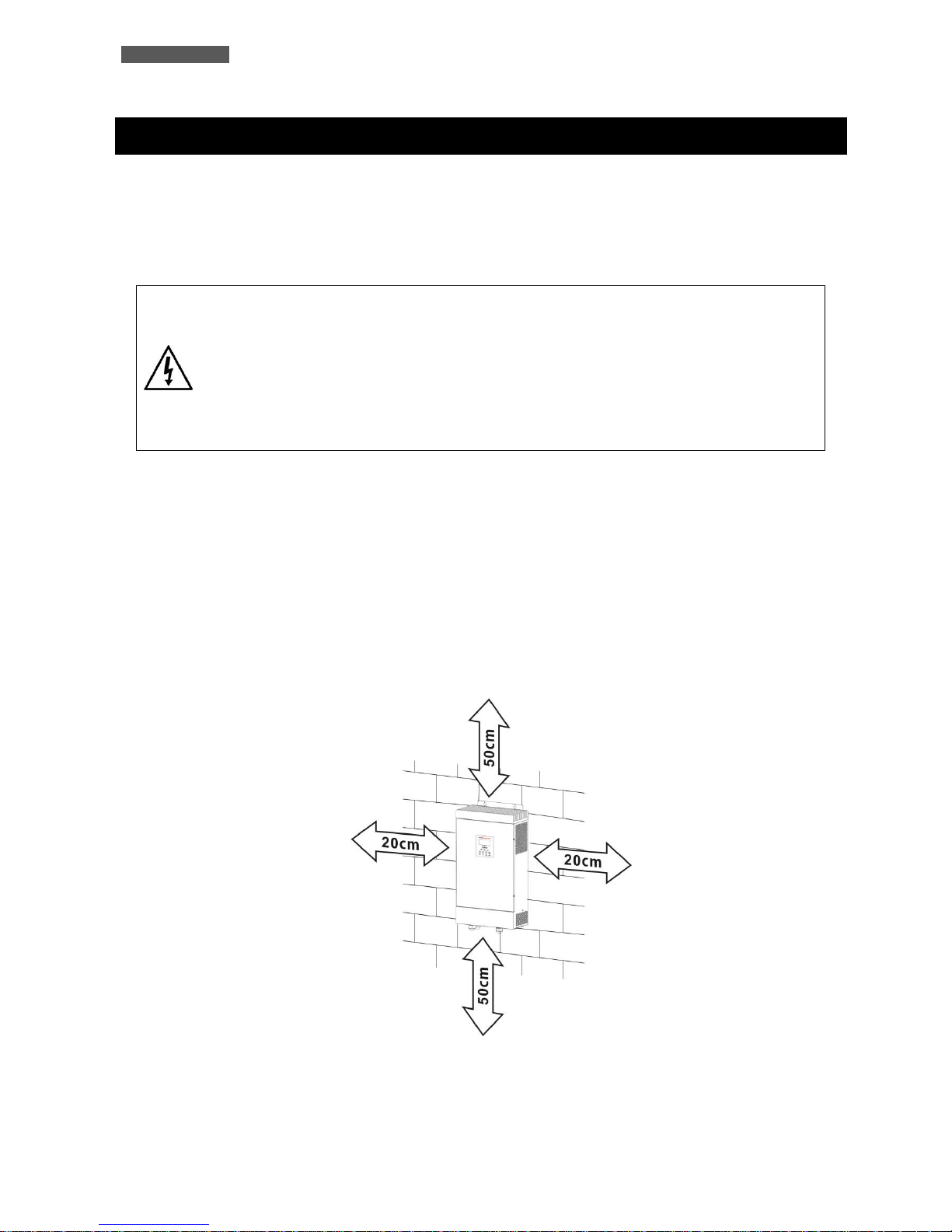
4. During normal operation the ATA discharges a minimal amount of heat. So it is necessary to leave at least 20
cm of unobstructed space on the side and 50 cm up and down of ATA in order to keep it properly ventilated.
ENGLISH
ATA Energy Storage System MM 5 User’s manual
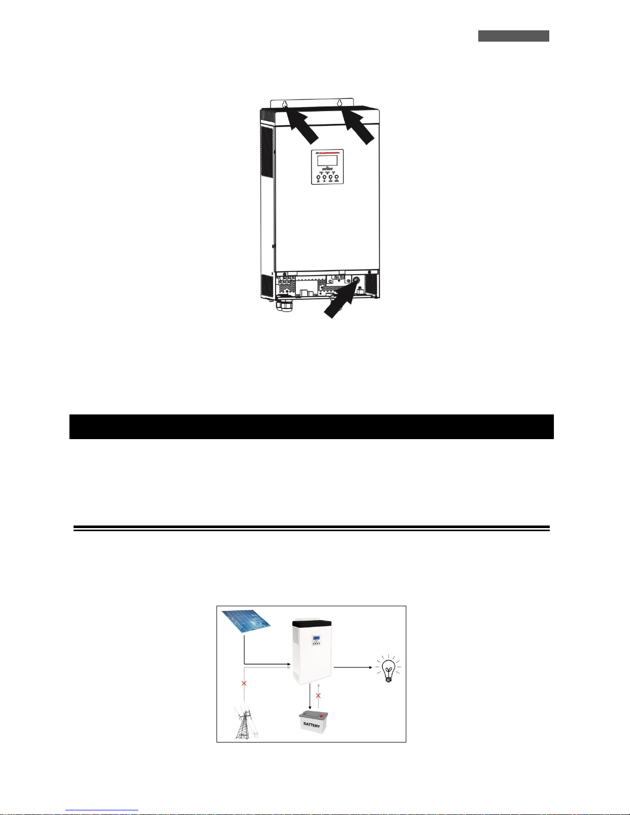
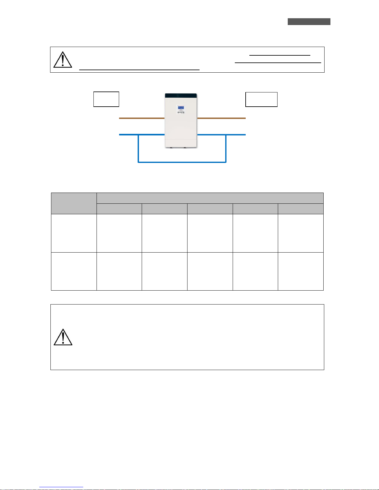
5. Fix ATA on the choice surface, through the use of screws and dowels. See the image below for the fixing point
on the ATA.
6. Do not obstruct ventilation holes.
7. Do not insert objects or pour liquids in the ventilation holes.
8. Do not rest any object on top of the ATA.
9. Do not keep liquids, flammable gases or corrosive substances near the unit.
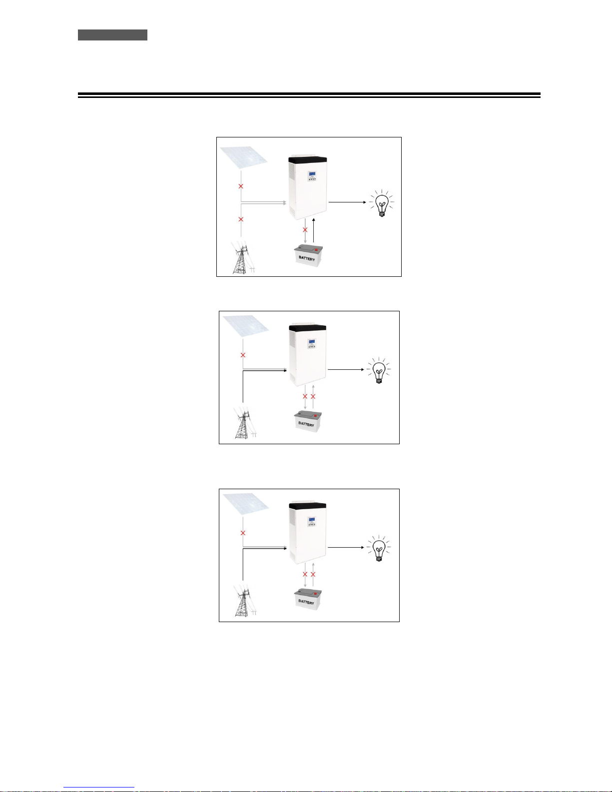
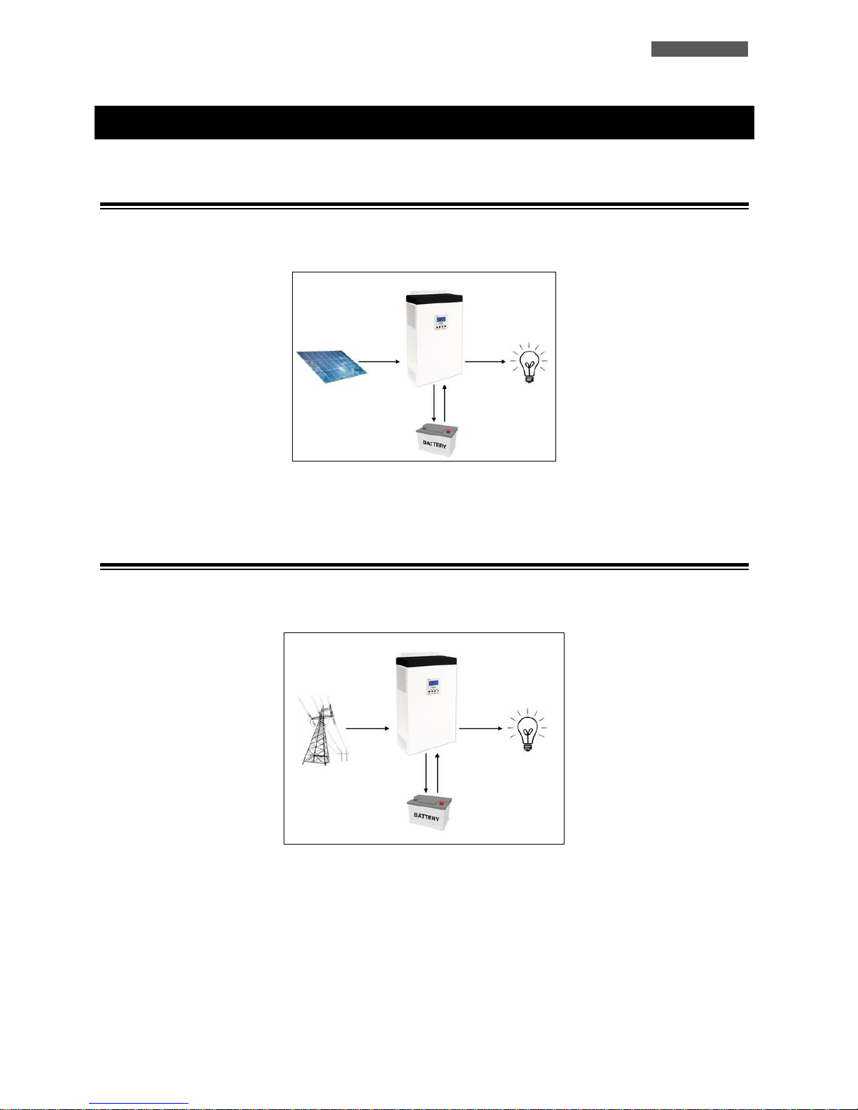
4 Operating
The typical mode of operation is the SBU mode: the acronym SBU indicates the order of priority of the power supply
used by ATA. The first source is S = SOLAR, i.e. solar panels; the second source is B = BATTERY, i.e. batteries; the third
source is U = UTILITY, i.e. the AC Utility Line.
4.1 Functioning with active PV panels
The equipment is powered by the ATA system by using the energy from the PhotoVoltaic (PV) panels. During this
phase, the ATA simultaneously charges the batteries and works independently without any need to use the mains. ATA
is equipped with a MMPT system (Maximum Power Point Tracker) that allows to find the best workable point to
maximize the power of solar panels, depending to the solar irradiation that they are exposed.
ENGLISH
User’s manual 6 ATA Energy Storage System MM
4.2 Functioning with inactive PV panels
The equipment is powered by the ATA system by using the energy stored in the batteries until the photovoltaic panels
are once again active. The stored energy can be used up to a minimum threshold of 30/40% (settable in settings).
Only in the case of this energy not being sufficient will the equipment be powered automatically from the mains.
Should a blackout occur during this phase, the ATA uses the 30/40% of energy remaining in the batteries (UPS function)
to power the equipment.
Once the residual energy has been used up, the system turns off. When the mains or the photovoltaic panels are
reactivated, the ATA Energy Storage System automatically starts up again.
When the battery charger level reaches the threshold value set, ATA Energy Storage System automatically switches to
active panels mode (see section 4.1).
ENGLISH
ATA Energy Storage System MM 7 User’s manual
5 Other Operating Modes
5.1 Only with PV panels
ATA system use the PhotoVoltaic (PV) Panels energy to power the equipment; simultaneously charges the batteries. In
the case the photovoltaic panels energy is not sufficient ATA use the batteries energy.
To active this modality you need to set correctly the parameters 01 and 16 in the ATA settings. See the chapter
“Settings”.
5.2 Only with the main (UPS)
ATA system use the mains to power the equipment; simultaneously charges the batteries. In the case the mains is not
available ATA use the batteries energy.
To active this modality you need to set correctly the parameters 01 and 16 in the ATA settings. See the chapter
“Settings”.
ENGLISH
User’s manual 8 ATA Energy Storage System MM
6 External Description
6.1 Front Panel
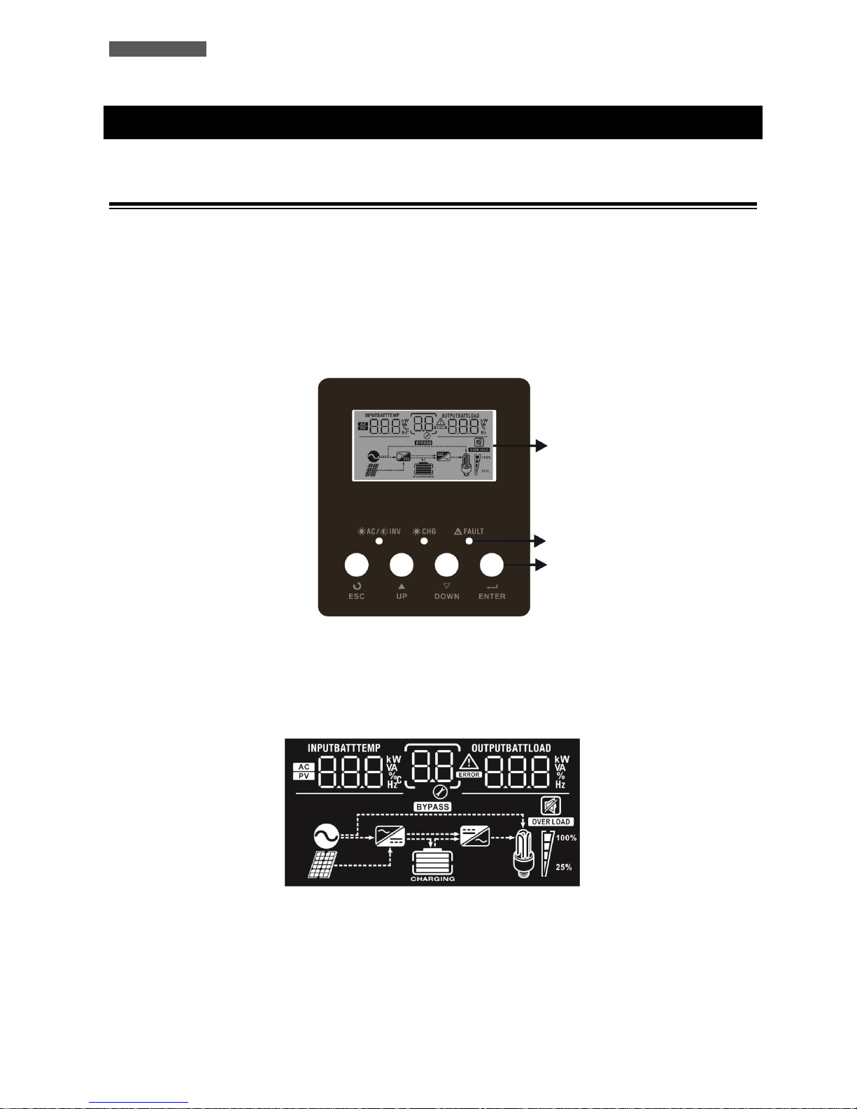
The front panel informs the user about operating status, alarm conditions and measurements. It also provides access to
controls and configuration parameters.
Front panel shown below consists of two parts:
1. Graphic LCD panel provides complete information about the functioning status and existing alarms, Load and
Battery level, Input, Output and Battery measurements.
2. 4 buttons enables the user to turn ON/OFF the ATA and to make selections of the functioning parameters.
Figure 1 – Front panel
6.1.1 Graphic LCD Panel
Please refer to figure 2.
Figure 2 – Graphic LCD Panel
LCD display
LED
Buttons
ENGLISH
ATA Energy Storage System MM 9 User’s manual
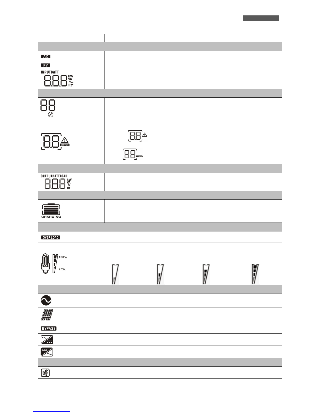
LCD Icon
Function Description
Input Source Information
Indicates the AC input.
Indicates the PV input
Indicates input voltage, input frequency, PV voltage, battery voltage and charger
current.
Configuration Program and Fault Information
Indicates the setting program.
Indicates the warning and fault codes.
Warning: flashing with warning code.
Fault: lighting with fault code
Output Information
Indicate output voltage, output frequency, load percent, load in VA and load in
Watt.
Battery Information
Indicates battery level by 0-24%, 25-49%, 50-74% and 75-100% in battery mode and
charging status in line mode.
Load Information
Indicates overload.
Indicates the load level by 0-24%, 25-50%, 50-74% and 75-100%.
0%~25%
25%~50%
50%~75%
75%~100%
Mode Operation Information
Indicates unit connects to the mains.
Indicates unit connects to the PV panel.
Indicates load is supplied by utility power.
Indicates the utility charger circuit is working.
Indicates the DC/AC inverter circuit is working.
Mute Operation
Indicates unit alarm is disabled.
ENGLISH
User’s manual 10 ATA Energy Storage System MM
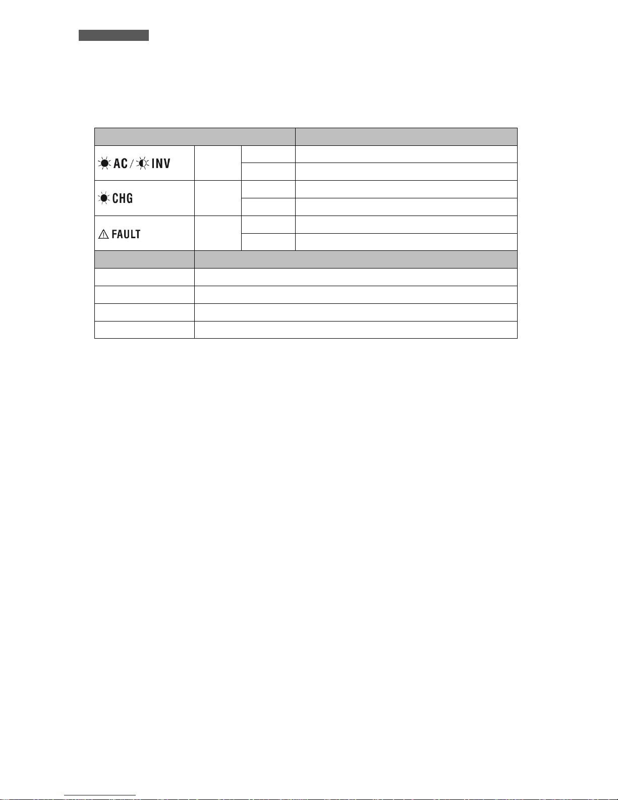
6.1.2 Led Indicator and Buttons
Functions of the buttons are given below:
LED Indicator
Messages
Blu
Solid On
Output is powered by utility in Line mode.
Flashing
Output is powered by battery or PV in battery mode.
Blu
Solid On
Battery is fully charged.
Flashing
Battery is charging.
Red
Solid On
Fault occurs in the inverter.
Flashing
Warning condition occurs in the inverter.
Button
Description
ESC
To exit setting mode
UP
To go to previous selection
DOWN
To go to next selection
ENTER
To confirm the selection in setting mode or enter setting mode
ENGLISH
ATA Energy Storage System MM 11 User’s manual
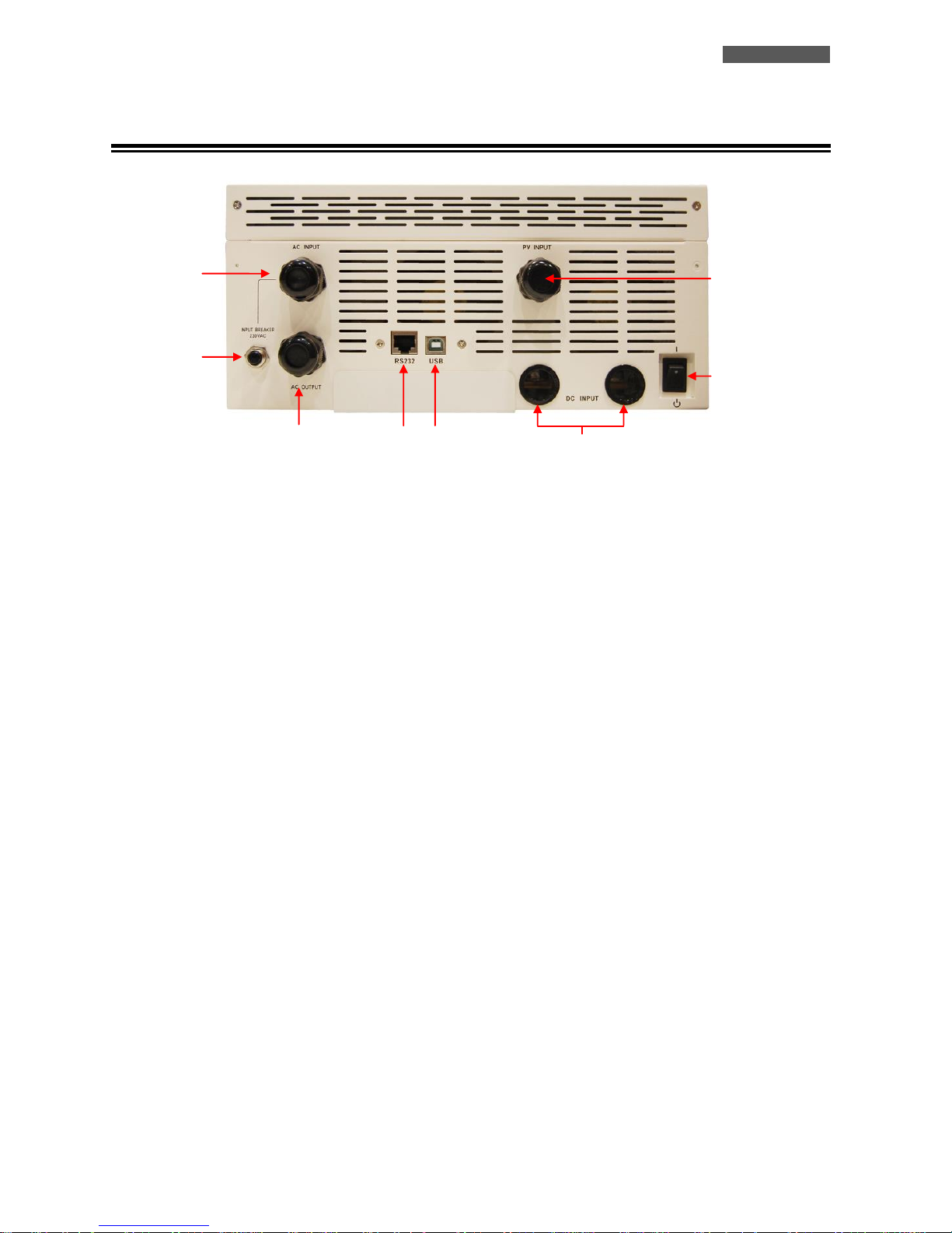
6.2 Rear Side
Figure 3 – Rear Side
1. Power On/Off Switch: to turn on or turn off the ATA
2. Grounded AC Input: to connect the ATA to the AC utility line.
3. PV Input: to connect the ATA to the PV panels.
4. Battery Input: to connect the ATA to the batteries.
5. Input Circuit Breaker: it goes off in Overload or short-circuit condition; push the external button of the Circuit
Breaker to reactivate it.
6. Grounded AC Output: to supply loads.
7. Computer Interface (RJ45/RS232 connector): it is the communication RJ45/RS232 port (through the cable RJ45-
RS232).
8. Computer Interface (USB connector): it is the communication USB port.
1
2
3
5 6 4 7 8
ENGLISH
User’s manual 12 ATA Energy Storage System MM
7 Electrical Installation
The electrical installation has to be done by qualified personnel. Follow all the Safety
Standards (CEI Standards in Italy or IEEE elsewhere) for the Input/Output connections
and for the right selection of Input/Output cables.
For safety we recommend using external circuit breaker between AC Mains line and
ATA Input line: the circuit breaker should be qualified as RCCB (Residual Current
Circuit Breaker RCCB) with leakage current protective function (leakage current < 300
mA).
For safety we recommend using external circuit breakers between ATA Output line
and the loads: the circuit breakers should be qualified as RCCB (Residual Current
Circuit Breaker RCCB) with leakage current protective function (leakage current < 30
mA).
It is also advisable to install a PV protection system between the PV panels line and the
PV panels Input of ATA, dimensioned according to the installed PV panels.
ATTENTION: for safety and efficiency it is recommended to use always cables with the
cross section equal or thicker than the specified one into the following table.
TECNOWARE declines any responsibility if these warnings are disregarded.
The ATA models have inside the case only the electronic parts: the batteries are installed externally.
Before starting the installation procedure, be sure that:
1. The AC Utility Line for the ATA has been removed, the PhotoVoltaic (PV) panels
and the batteries pack are disabled.
2. The ATA is completely OFF (only if graphic LCD panel is OFF).
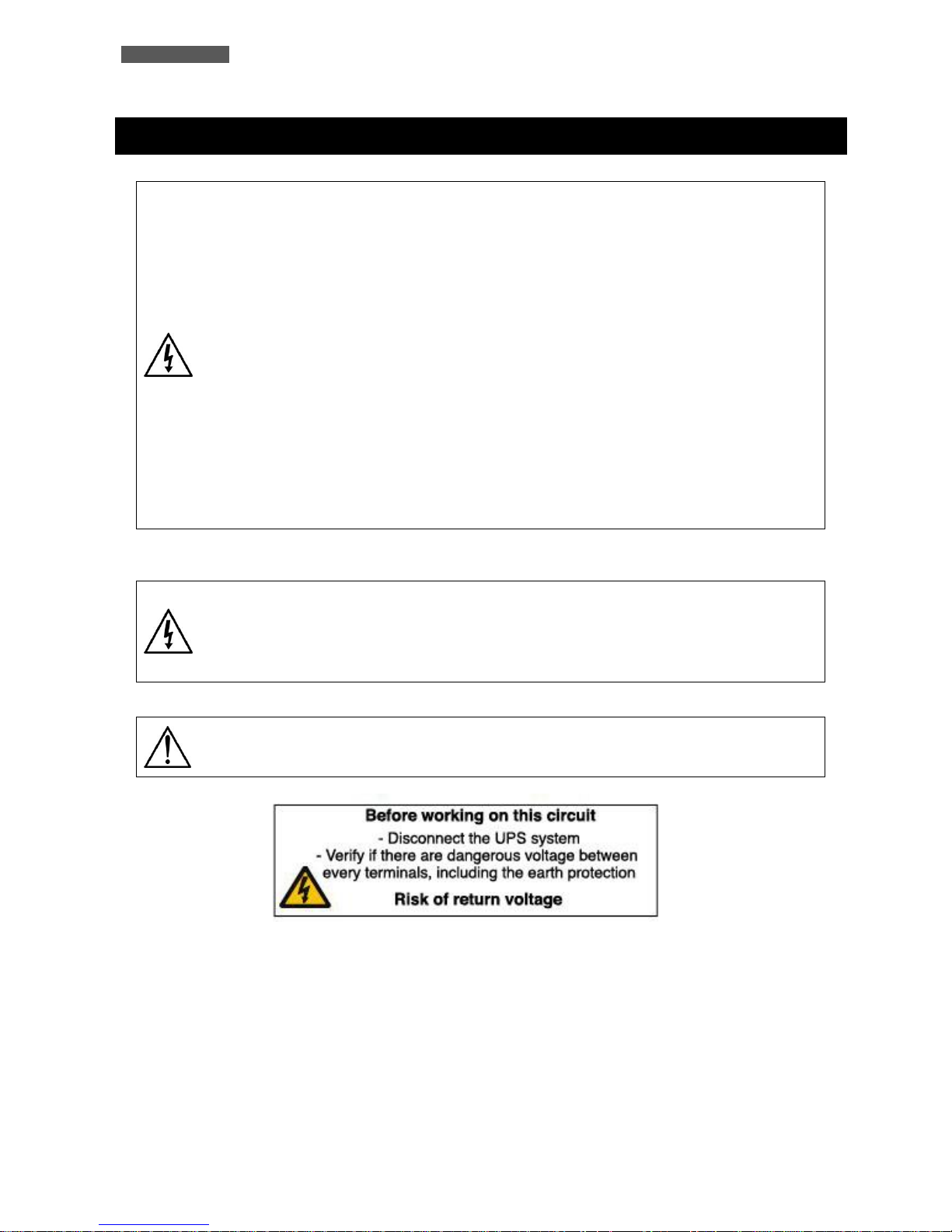
Is necessary to apply a label, as the following one, into the AC input and output
distribution box.
ENGLISH
ATA Energy Storage System MM 13 User’s manual
When ATA works with the PV panels and/or the batteries the Neutral is not through. To
recreate the same input supply system (AC input main), the neutral line of output must
be connected with the neutral line of input. See the image below.
The following table shows the recommended size for wires.
Model
Wiring spec (cross section mm2 - AWG)
Input
PV panels
Batteries
Output
Ground
ATA 4.0 MM
6 mm
2
or
10 AWG
8 mm
2
or
8 AWG
2 x 8 mm2
or 2 x 8 AWG
(2 cables together
with a single
cable lugs)
6 mm2 or
10 AWG
6 mm2 or
10 AWG
ATA 5.0 MM
8 mm
2
or
8 AWG
8 mm
2
or
8 AWG
2 x 8 mm2
or 2 x 8 AWG
(2 cables together
with a single
cable lugs)
8 mm
2
or
8 AWG
8 mm2 or
8 AWG
The wires for ATA 4.0 MM must be designed to withstand currents up to 29A if using
for AC Utility Line, up to 60A (PV panels), up to 75A (Batteries) and up to 18A (Output
Line). For security and reliability you need to use cables with a cross section not less
than those indicated in the table above.
The wires for ATA 5.0 MM must be designed to withstand currents up to 29A if using
for AC Utility Line, up to 60A (PV panels), up to 93A (Batteries), and up to 22A (Output
Line). For security and reliability you need to use cables with a cross section not less
than those indicated in the table above.
INPUT
OUTPUT
LINE
LINE
NEUTRAL
NEUTRAL
ENGLISH
User’s manual 14 ATA Energy Storage System MM
7.1 Installation
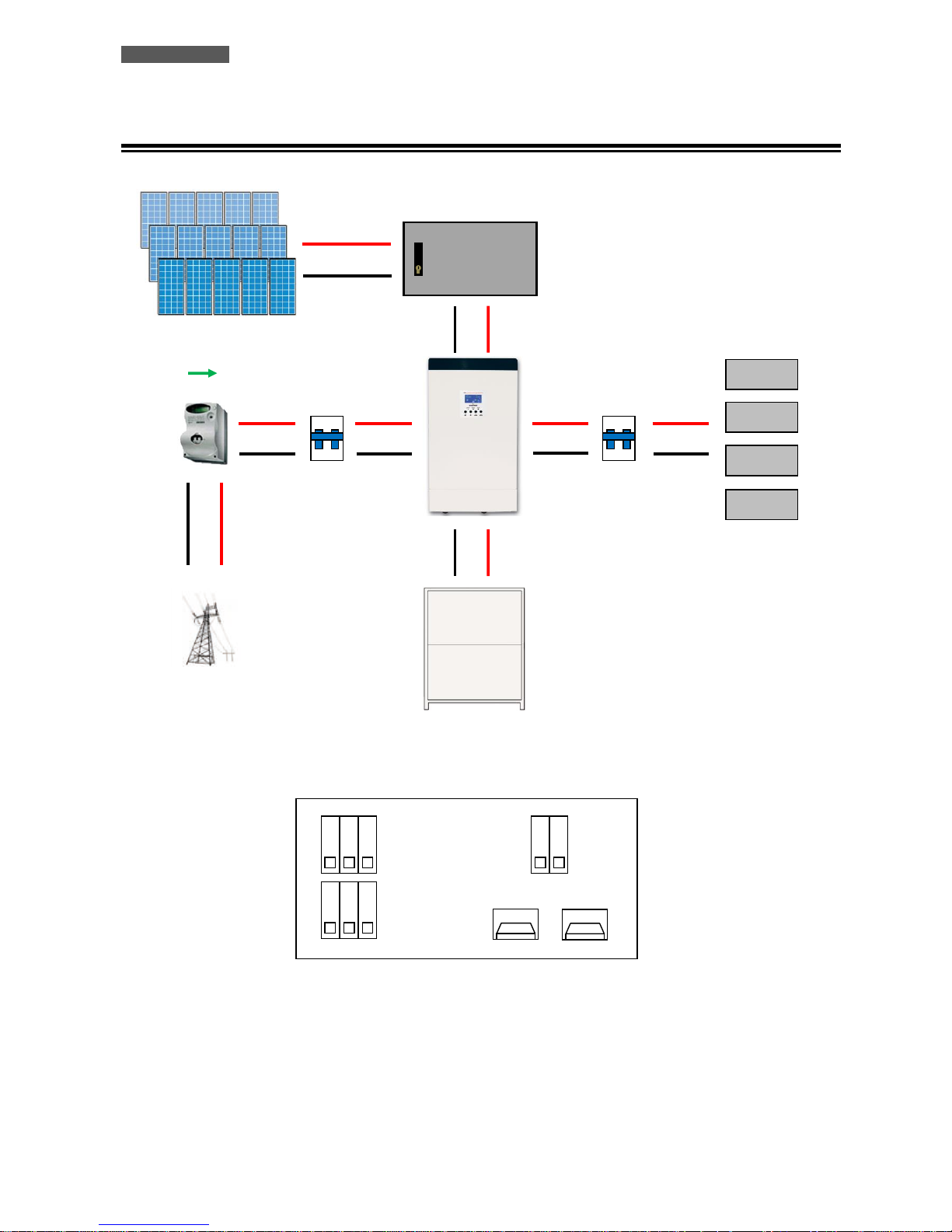
Figura 4 – ATA installation and connection
ON
OFF
ON
OFF
LOAD
RCCB
(Residual Current
Circuit Breaker)
30mA (existing)
RCCB
(Residual Current
Circuit Breaker)
ELECTRICITY
METER (existing)
PV PROTECTION
SYSTEM
PV PANELS
ATA ENERGY
STORAGE SYSTEM
BOX BATTERIE ATA
AC MAINS LINE
ATA CONNECTIONS
+ BATTERY
- BATTERY
G L N
G L N
AC MAINS INPUT
OUTPUT
PV PANELS INPUT
PV+
PV-
ENGLISH
ATA Energy Storage System MM 15 User’s manual
We advise you to follow the steps below explained:
1. Connect the ATA Input line to the AC mains line (see figure 4). It is mandatory to ground the AC mains line
according to the Safety Standards. Carefully check the grounding of AC mains line. For safety we recommend to
install an external circuit breaker (RCCB type, with leakage current < 300 mA) between AC mains line and ATA
Input line (see figure 4).
2. Connect the line of the PhotoVoltaic panels to the ATA units (see Figure 4). Pay attention to connect the panels
in such a way as to meet the specifications (see the chapter "Technical Specifications").
2.1 Each series of panels shall not exceed the maximum open circuit voltage of 145 Voc.
2.2 The peak power supplied by PhotoVoltaic panels is 3750 Wp.
2.3 Therefore, we assume the use of 250 Wp panels with a rated voltage of 37.7 Vdc, it will be possible to build
a system like the following:
2.3.1 Using PhotoVoltaic panels with a nominal voltage of 37.7 Vdc, it will be able to achieve a serie of panels
(named string) with up to 3 panels because:
3 x 37,7 = 113,1Vdc, that is less than the maximum open circuit voltage of 145 VOC.
2.3.2 Using PhotoVoltaic panels with a power of 250 Wp, it will be able to achieve up to 5 strings of panels
connected in parallel because:
The peak power of each string = 3 x 250 = 750 Wp (number of panels in a string multiplied by the peak
power of each panel).
The peak power of the system = 5 x 750 = 3750 Wp (number of strings multiplied by the peak power of
each string).
2.4 It is also advisable to install a PV protection system between the PV panels line and the PV panels Input of
ATA, dimensioned according to the installed PV panels
3. Connect the devices to be supplied to the ATA outputs. Be sure all the devices have the main switch in OFF
position. For safety we recommend to install an external circuit breaker (RCCB type, with leakage current < 30
mA) between ATA Output line and the loads (see figure 4).
4. Connect ATA to the external Battery Box:
We suggest to use ONLY Battery Box supplied by TECNOWARE. TECNOWARE declines
any responsibilities if this rule is not followed.
Before starting whichever operation be sure that the Battery circuit breaker of Battery
Box is in “OFF” position.
4.1 The ATA unit is designed to operate with a nominal voltage from batteries equal to 48 Vdc (4 x 12Vdc).
4.2 After connecting the battery (follow the instructions of battery box user manual), check the right polarity
and the total voltage of the battery pack.
4.3 Connect the box battery to the ATA, via the cables supplied with the battery box.
ENGLISH
User’s manual 16 ATA Energy Storage System MM
It is compulsory to ground the ATA according to the Safety Standards.
The case of the ATA is internally connected to the ground terminal (GND) of the
IN/OUT terminals, in order to guarantee safety to the user. To guarantee safety it is
necessary to be sure that the local electric plant is supplied with GROUND (in
compliance with the Safety Standards), and that a valid connection is guaranteed
between the GROUND of the UPS and the GROUND of the local electric plant.
Any interruption of the GROUND conductor is absolutely prohibited.
Risk of electric shock at the Output lines if the ATA is ON, even when the ATA is not
connected to AC utility line.
Risk of electric shock at the Output lines while the unit is connected to the AC utility
line.
Risk of electric shock: do not remove the cover. The ATA contains internal parts which
are at a high Voltage and are potentially dangerous, capable of causing injury or death
by electric shock.
There are no internal parts in the ATA which are user serviceable. Any repair or
maintenance work must be performed exclusively by qualified technical personnel
authorized by TECNOWARE. TECNOWARE declines any responsibility if this warning is
disregarded.
Disregard for these warnings may lead to a risk of electric shock to operators.
8 First Start Up
Turning the ATA is very easy. Nevertheless we recommend that, on First Start Up, the following procedure is
observed for greater safety.
1. Be sure the circuit breaker of ATA outputs is in “OFF” position.
2. Place the circuit breaker of external batteries in “ON” position.
3. Place the circuit breakers of PV panels in “ON” position.
4. Place the AC Input line circuit breaker of ATA in “ON” position.
5. As a consequence of point 4, the ATA turns on the graphic display and goes in Stand-by mode: the ATA doesn’t
supply Output power and recharges only the batteries in accordance with SBU mode.
6. Place the On/Off switch of the ATA in “ON” position: the ATA emits a brief acoustic signal and performs a
functioning SELF-TEST. After some seconds the ATA starts to work in SBU mode and the graphic LCD panel will
show the path of energy.
7. Place the circuit breaker of ATA outputs is in “ON” position. Then turn ON the devices (one by one) to be supplied
by ATA, checking the ATA doesn’t report Overload information on the graphic LCD panel and all the devices are
working regularly.
ENGLISH
ATA Energy Storage System MM 17 User’s manual
9 Functioning
9.1 Turning ON and OFF
To turn completely ON the ATA please do the following steps:
Place the circuit breaker of external batteries in “ON” position.
Place the circuit breakers of PV panels in “ON” position.
Place the AC Input line circuit breaker of ATA in “ON” position.
Place the On/Off switch of the ATA in “ON” position.
The graphic LCD panel provides complete information about the functioning status.
To turn completely OFF the ATA please do the following steps:
Place the On/Off switch of the ATA in “OFF” position: the ATA switches in Stand-
by mode.
Place the AC Input line circuit breaker of ATA in “OFF” position.
Place the circuit breaker of external batteries in “OFF” position.
Place the circuit breakers of PV panels in “OFF” position.
The graphic LCD panel and the leds on the front panel are OFF only when the UPS is
completely OFF.
The ATA can be turned on even in the absence of production from PV panels and in the absence of AC mains.
9.2 Low Battery and Automatic Restart
The ATA reaches the Low Battery condition whenever the batteries reach a charge level allowing the connected
devices to operate for few minutes (about 10% of max charge), following its use without other sources of energy (AC
mains is not available, and the production from PV panels is off).
The UPS warns operators of Low Battery by lighting of the LOW BATT. icon on the graphic LCD.
If the AC mains (or the production from the PV panels) is not restored within a few minutes, the UPS shuts-down
automatically thus preventing the batteries from discharging excessively; the ATA stops supplying Output power,
deactivates control panel indication and goes to a waiting state. Once AC mains (or the production from the PV panels)
is comes back on, the ATA restarts automatically and after some seconds it goes back to work in SBU mode.
The battery charging takes place only when the voltage from the PV panels is present and sufficient.
ENGLISH
User’s manual 18 ATA Energy Storage System MM
9.3 Load Testing
The UPS indicates the Output Load level by graphic LCD (as described in the chapter 5).
When the Output load is higher then nominal value the ATA warns of Overload condition by graphic LCD and by
acoustic alarm as described in the “Warning Table” and in the “Troubleshooting” chapter.
The UPS has the capability to accept an Overload less than 110% for 10 minutes.
An Overload between 110% and 150% is accepted for about 10 seconds and after ATA switches automatically to the
Bypass mode.
An Overload between 150% and 200% is accepted for about 5 seconds and after ATA switches automatically to the
Bypass mode..
Once the requested power is back within range, the ATA switches automatically to the SBU mode.
Make sure that the ATA never indicates Overload condition.
Do not connect a load greater than rated value to the ATA (see POWER specifications
in the chapter “Technical Characteristics”), as this may damage the unit. In this case
the warranty is void.
9.4 Operation in Warning Status
During a warning condition the buzzer beeps, it means that there are some problems for ATA operation. Users can get
the Fault code from graphic LCD panel. Please check the “Troubleshooting” chapter for details.
Below you can see the “Warning Table”, with the correspondence between each warning and the relative signals
(icons on graphic LCD and acoustic alarm) for the user.
WARNING
ICON (flashing)
CODE
ACOUSTIC ALARM
Fan is locked when inverter is on.
01
Beep three times every
second
Battery is over-charged
03
Beep once every second
Low battery
04
Beep once every second
Overload
07
Beep once every 0.5 second
Output power derating
10
Beep twice every 3 seconds
Solar charger stops due to low
battery.
12
Solar charger stops due to high PV
voltage.
13
Solar charger stops due to
overload.
14
Warning Table
ENGLISH
ATA Energy Storage System MM 19 User’s manual
9.5 Operation in Fault Mode
When Fault led illuminates and the buzzer beeps continuously, it means that there is a fatal error in the ATA. Users
can get the Fault code from display panel. Please check the “Troubleshooting” chapter for details.
Please check the loads, wiring, ventilation, mains supply, PC supply, Battery and so on after the fault occurs. Don’t try
to turn ON the ATA again before solving the problems. If the problems can’t be fixed, please contact Technical Service
immediately.
In case of emergency, please disconnect the connection from mains supply, PV supply,
external Battery, and Output immediately to avoid further risk or danger.
Below you can see the “Fault Table”, with each Fault event and the relative FAULT code/icon on graphic LCD for the
user’s information.
FAULT EVENT
FAULT CODE
ICON
FAULT EVENT
FAULT CODE
ICON
Fan is locked when inverter
is off.
01
Main relay failed
11
Over temperature
02
Over current or surge
51
Battery voltage is too high
03
Bus voltage is too low
52
Battery voltage is too low
04
Inverter soft start failed
53
Output short circuited or
over temperature is
detected by internal
converter components.
05
Over DC voltage in AC output
55
Output voltage is too high.
06
Battery connection is open
56
Overload time out
07
Current sensor failed
57
Bus voltage is too high
08
Output voltage is too low
58
Bus soft start failed
09
Fault Table
ENGLISH
User’s manual 20 ATA Energy Storage System MM
10 Communication Interfaces
The ATA unit is factory-equipped with RJ45/RS232 and USB Communication Interfaces, usable as communication ports
with a Personal Computer.
Only one of the RS232/USB communications can be activated at one time. To activate RJ45/RS232 communication it
is sufficient to connect the RJ45/RS232 cable only; to activate USB communication it is sufficient to connect the USB
cable only.
The RJ45/RS232 and USB interface signals are isolated through photo-couplers.
Connecting to the Web site www.tecnoware.com it is possible to download free of charge the updated Management
Software for ATA, named WatchPower, compatible with the most popular Operating Systems.
It is possible to add an Interface RS485 (optional).
10.1 WatchPower
The management software WatchPower allows to monitor the operation of the system, to monitor the electrical
variables (current from PV panels, current from batteries, battery capacity, power output, working frequency and
other variables), to set the ATA functioning parameters, to record the data generated by the system, to see the
graphical representation of recorded data in function of time, and to extrapolate these data to an Excel file. You can
also set the alert by mail of any anomalies detected by the system.
In order to change the settings of the system is required to login as administrator. The default password is
"administrator". It is possible to change the password after the first login with the default password.
10.1.1 System Monitoring
From the above screen, you can display the values of the system. The diagram shows which parts of the system
are active.
The values of the operation of the system are displayed in real time and indicate the voltage and input
frequency, the voltage and the current generated by the PV panels, the voltage, the capacity, the charging and
discharging current of the batteries (when supplying energy to the load ) , the voltage and frequency output
and information related to the absorption of the connected devices (active and apparent power and its
percentage).
ENGLISH
ATA Energy Storage System MM 21 User’s manual
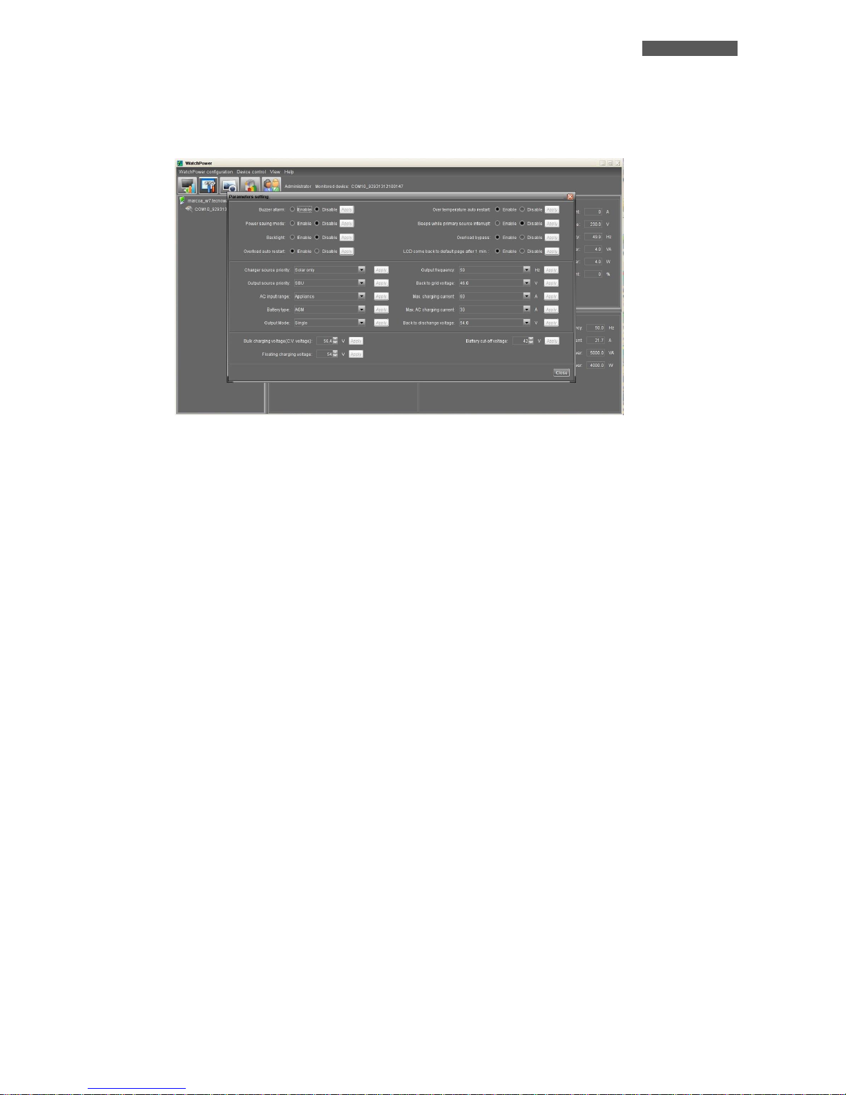
10.1.2 Setting the operating parameters of ATA
By clicking on the "Parameters Setting", you can select the same settings that can be set by the front panel.
These settings affect the operation of the entire system. And it is possible to enable or disable alarms and
functions (acoustic alarm, warning in the absence of AC mains line, power saving mode, backlight, reboot in
case of overload and/or bypass, etc ...), to select the functioning mode (SBU, Utility, etc ... ), to select the
priority of power for the loads (only by solar panels, only by AC Utility Line, hybrid between AC Utility Line and
PV panels), to select the operating parameters of the batteries (maximum voltage charging, charging current,
maintenance voltage, minimum voltage of work for which the system then feeds the loads by AC Utility Line)
and to select parallel or three-phase mode.
To apply any changes you need to login as administrator. It is advisable to make such changes to qualified
personnel.
ENGLISH
User’s manual 22 ATA Energy Storage System MM
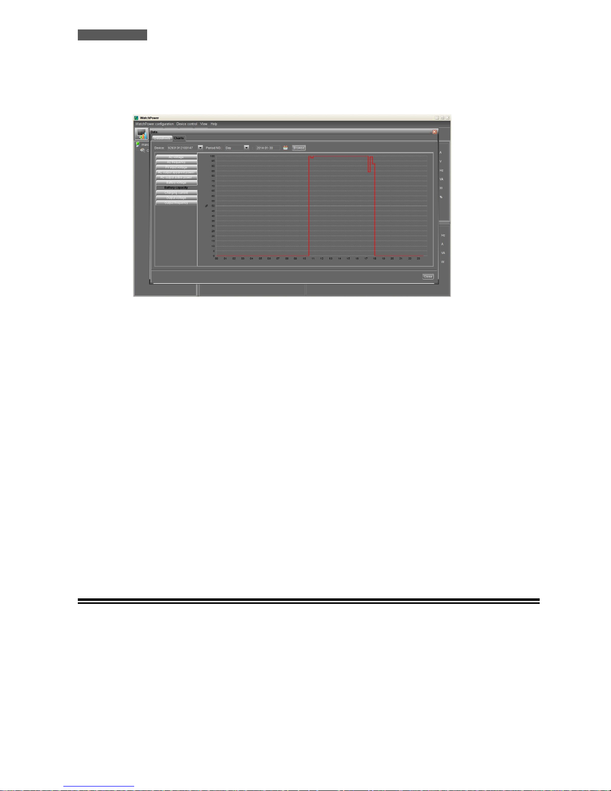
10.1.3 Recording and graphical representation of the values of the System
ATA has a system of storing the historical operation values. It is possible to view these values graphically or
extrapolate on Excel file. You can access the historical clicking on the "Data" button.
In the graphic representation, you can select the type of parameter to be displayed going to perform filtering
on the time in which you are interested. This filtering can be done by hour, day, month and year.
The same type of filtering (by hour, day, month and year) may be carried out for the data to extrapolate on
Excel file.
10.1.4 Other Functions
The program allows you to use other functions such as sending e-mail messages, changing the default password,
setting the update times, storing the values of the system, and selecting, historicizing and extrapolating the
anomalies to an Excel file.
By accessing the menu "WatchPower Configuration" you can set the sending of e-mail messages, by configuring
your mail server to use, email recipients and the events that cause the e-mail messages.
By clicking on the "Event Log" you can set the filtering (by hour, day, month and year) of the anomalies found
during the operation of the system and set the view or extrapolation on an Excel file.
By clicking on the "Basic" you can set the time to update the values produced by the system in real time,
recording interval of those values and the date format that appears.
10.2 RS485 Interface
You can use an RS485 Interface to make compliant the ATA unit with the RS485 communication Standard. The RS485
Interface is optional.
ENGLISH
ATA Energy Storage System MM 23 User’s manual
11 Parallel System Connection
11.1 Introduction
Maximum of 4 pcs of identical power and specification ATA can be connected in parallel: so the max handling power is
20KVA/16KW (for ATA 5.0 MM).
11.2 Parallel Kit
The parallel kit consists of:
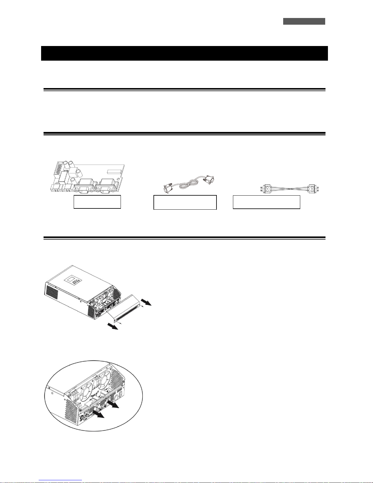
11.3 Parallel Kit Installation
1. Remove the metal cover, see the following figure.
2. Remove the Communication Board (with RJ45 and USB port).
Parallel Board
Parallel Cable
Sharing Current Cable
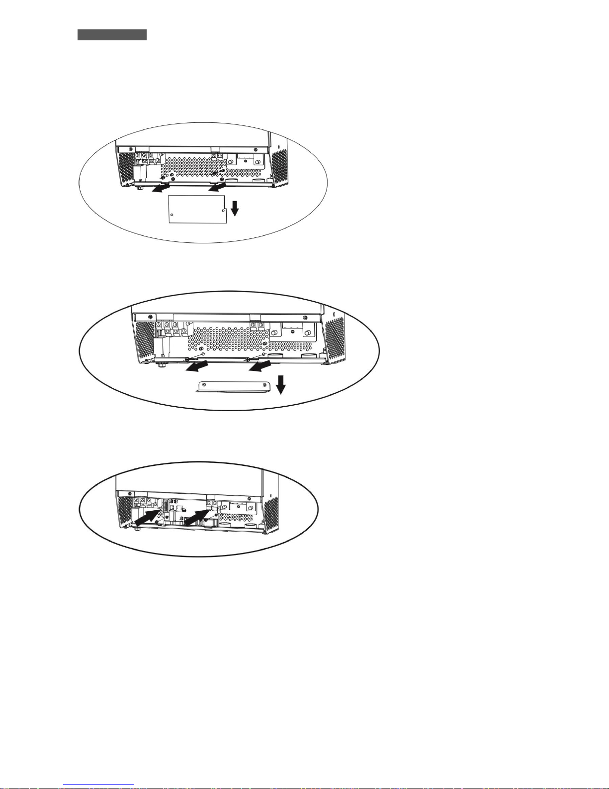
ENGLISH
User’s manual 24 ATA Energy Storage System MM
3. Remove the screws, as shown below; then remove the 2-pin flat cable, remove the 14-pin flat cable and remove the
electronic board placed under the communication board.
4. Remove the metal cover, as shown below.
5. Install the Parallel Board.
 Loading...