

Page 1

Uninterruptible Power Supply
ATA Energy Storage System
ATA 4.0 MM
ATA 5.0 MM
User’s manual
Manuale utente
Page 2

Page 3

Index
User’s Manual - English........................................................................ 1
Safety Warnings ................................................................................ 1
1 Introduction .............................................................................. 2
2 General Characteristics ................................................................. 3
3 Receipt and site selection .............................................................. 4
4 Operating .................................................................................. 5
4.1 Functioning with active PV panels ................................................5
4.2 Functioning with inactive PV panels .............................................6
5 Other Operating Modes ................................................................. 7
5.1 Only with PV panels .................................................................7
5.2 Only with the main (UPS) ..........................................................7
6 External Description .................................................................... 8
6.1 Front Panel ...........................................................................8
6.1.1 Graphic LCD Panel ............................................................................ 8
6.1.2 Led Indicator and Buttons .................................................................. 10
6.2 Rear Side ........................................................................... 11
7 Electrical Installation .................................................................. 12
7.1 Installation ......................................................................... 14
8 First Start Up ............................................................................ 16
9 Functioning .............................................................................. 17
9.1 Turning ON and OFF .............................................................. 17
9.2 Low Battery and Automatic Restart ............................................ 17
9.3 Load Testing ....................................................................... 18
9.4 Operation in Warning Status ..................................................... 18
9.5 Operation in Fault Mode ......................................................... 19
10 Communication Interfaces ............................................................ 20
10.1 WatchPower ........................................................................ 20
10.2 RS485 Interface .................................................................... 22
11 Parallel System Connection ........................................................... 23
11.1 Introduction ........................................................................ 23
11.2 Parallel Kit ......................................................................... 23
11.3 Parallel Kit Installation ........................................................... 23
11.4 Installation of ATA units .......................................................... 26
11.5 Batteries Connection ............................................................. 26
11.6 AC Utility Line Connection ....................................................... 28
11.7 Output Lines and Load Connection ............................................. 29
11.8 PhotoVoltaic (PV) Panel Connection ............................................ 29
11.9 Connections of Parallel Kit cables .............................................. 30
11.10 Setting Parameter ................................................................. 31
11.11 Startup .............................................................................. 33
11.12 Faults and Alarms ................................................................. 34
12 Three Phases Connection ............................................................. 35
12.1 Introduction ........................................................................ 35
12.2 Parallel Kit ......................................................................... 35
12.3 Parallel Kit Installation ........................................................... 35
12.4 Installation of ATA units .......................................................... 38
Page 4

12.5 Batteries Connection ............................................................. 38
12.6 AC Utility Line Connection ....................................................... 40
12.7 Output Lines and Load Connection ............................................. 41
12.8 PhotoVoltaic (PV) Panel Connection ............................................ 42
12.9 Connections of Parallel Kit cables .............................................. 42
12.10 Setting Parameter ................................................................. 43
12.11 Startup .............................................................................. 44
12.12 Faults and Alarm ................................................................... 45
13 Technical Characteristics .............................................................. 46
14 Settings ................................................................................... 48
15 Maintenance ............................................................................. 54
15.1 ATA Cleaning ....................................................................... 54
15.2 Battery .............................................................................. 54
15.3 Operator Safety .................................................................... 54
16 Troubleshooting ......................................................................... 55
Conformity to the European Directives ................................................... 57
Product Disposal ............................................................................... 57
Lead Batteries ................................................................................. 57
Page 5

Indice
Manuale Utente – Italiano.................................................................... 59
Avvisi di Sicurezza ............................................................................ 59
1 Introduzione ............................................................................. 60
2 Caratteristiche Generali ............................................................... 61
3 Ricevimento e Collocazione .......................................................... 62
4 Funzionamento ......................................................................... 63
4.1 Modalità SBU: funzionamento con Pannelli Attivi ............................ 63
4.2 Modalità SBU: funzionamento con Pannelli non Attivi ....................... 64
5 Altri Modi di Funzionamento ......................................................... 65
5.1 Modalità Only Solar: solo con Pannelli Fotovoltaici .......................... 65
5.2 Modalità Utility: solo con la Rete Elettrica .................................... 65
6 Descrizione Esterna .................................................................... 66
6.1 Pannello Frontale ................................................................. 66
6.1.1 Pannello LCD Grafico ....................................................................... 66
6.1.2 Led e Pulsanti ................................................................................ 68
6.2 Pannello Posteriore ............................................................... 69
7 Installazione Elettrica .................................................................. 70
7.1 Installazione ....................................................................... 72
8 Prima Accensione ....................................................................... 74
9 Funzionamento ......................................................................... 75
9.1 Accensione e Spegnimento ...................................................... 75
9.2 Fine Autonomia e Riaccensione Automatica .................................. 75
9.3 Controllo del Carico ............................................................... 76
9.4 Segnalazioni di Allarme .......................................................... 76
9.5 Segnalazioni di Guasto............................................................ 77
10 Interfacce di Comunicazione ......................................................... 78
10.1 WatchPower ........................................................................ 78
10.2 Interfaccia RS485 .................................................................. 80
11 Modalità Connessione Parallelo ...................................................... 81
11.1 Introduzione ....................................................................... 81
11.2 Contenuto Confezione del Kit Parallelo........................................ 81
11.3 Installazione Kit Parallelo ........................................................ 81
11.4 Installazione Unità ................................................................ 84
11.5 Connessione Batterie ............................................................. 84
11.6 Connessione Alimentazione d’Ingresso ......................................... 86
11.7 Connessione Circuito d’Uscita e Carico ........................................ 87
11.8 Connessione Pannelli Fotovoltaici .............................................. 87
11.9 Connessione Cavi del Kit ......................................................... 88
11.10 Impostazione Parametro ......................................................... 89
11.11 Messa in Servizio .................................................................. 91
11.12 Anomalie ed Allarmi del Sistema ............................................... 92
12 Modalità Connessione Trifase ........................................................ 93
12.1 Introduzione ....................................................................... 93
12.2 Contenuto Confezione Kit Parallelo ............................................ 93
12.3 Installazione Kit Parallelo ........................................................ 93
12.4 Installazione Unità ................................................................ 96
Page 6

12.5 Connessione Batterie ............................................................. 96
12.6 Connessione Alimentazione d’Ingresso ......................................... 98
12.7 Connessione Circuito d’Uscita e Carico ........................................ 99
12.8 Connessione Pannelli Fotovoltaici ............................................ 100
12.9 Connessione Cavi del Kit ....................................................... 100
12.10 Impostazione Parametro ....................................................... 101
12.11 Messa in Servizio ................................................................. 102
12.12 Anomalie ed Allarmi del Sistema .............................................. 103
13 Caratteristiche Tecniche ............................................................ 104
14 Settaggi ................................................................................. 106
15 Manutenzione.......................................................................... 112
15.1 Pulizia dell’ATA .................................................................. 112
15.2 Batterie ........................................................................... 112
15.3 Sicurezza dell’Operatore ....................................................... 112
16 Anomalie ed Interventi .............................................................. 113
Conformità alle Direttive Europee ....................................................... 115
Smaltimento del Prodotto ................................................................. 115
Batterie al Piombo .......................................................................... 115
Page 7
ENGLISH
ATA Energy Storage System MM 1 User’s manual
User’s Manual - English
Safety Warnings
Read this manual carefully and completely before installing and using ATA ENERGY STORAGE
SYSTEM, which, from here after, will also be referred to as ATA.
ATA must be used only by properly trained personnel. To ensure correct and safe operations, it is
necessary that operators and maintenance personnel observe the general safety Standards as well
as the specific instructions included in this manual.
Risk of electric shock: do not remove the cover. ATA contains internal parts which are at a high
Voltage and are potentially dangerous, capable of causing injury or death by electric shock.
There are no internal parts in ATA which are user serviceable. Any repair or maintenance work
must be performed exclusively by qualified technical personnel authorized by TECNOWARE.
TECNOWARE declines any responsibility if this warning is disregarded.
The electric installation has to be done by qualified personnel. Follow all the Safety Standards (CEI
Standards in Italy or IEEE elsewhere) for the Input/Output connections and for the right section of
Input/Output cables.
It is compulsory to ground ATA according to Safety Standards.
Risk of electric shock at the Output lines when ATA is ON.
Risk of electric shock at the Output lines while the unit is connected to the AC utility line.
For respect of the Safety Standards is necessary the presence of a differential circuit breaker
between ATA Output lines and the loads.
We recommend to use a dedicate AC power line for ATA.
Do not obstruct ventilation slots or holes and do not rest any object on to p of ATA.
Do not insert objects or pour liquids in the ventilation holes.
Install ATA indoors, in a protected, clean and moisture-free environment.
Do not expose to the direct sun light.
Do not keep liquids, flammable gases or corrosive substances near ATA.
Page 8
ENGLISH
User’s manual 2 ATA Energy Storage System MM
1 Introduction
The ATA ENERGY STORAGE SYSTEM (ATA means Uninterruptible Power Supply) is the result of constant technological
research aimed at obtaining the best performance at the lowest cost.
ATA ENERGY STORAGE SYSTEM is an inverter with storage system and single-phase sinewave UPS functioning built
specifically to protect and supply the most sophisticated electronic equipment: it provides to make an absolutely
continuous power supply, regulated and free to any kind of interference (black-out, under voltage, over voltage,
surge, spike, micro interruptions, interference).
The security for the load is guaranteed, also if occurs an overload status or an inverter failure, thanks a static bypass
that exclude ATA ENERGY STORAGE SYSTEM and connect the loads directly with the AC input main.
ATA ENERGY STORAGE SYSTEM is equipped with a communication interface RJ45 and USB that can be used to
communicate with the software WatchPower.
Read this manual carefully before using the ATA ENERGY STORAGE SYSTEM; it includes
important safety warnings and useful advices for correct use and installation.
ATA ENERGY STORAGE SYSTEM is constantly being developed and improved: consequently, your unit may differ
somewhat from the description contained in this manual.
This manual includes the following models:
ATA Energy Storage System 4.0 MM (4000VA, 3200W, 3750Wp max from PV)
ATA Energy Storage System 5.0 MM (5000VA, 4000W, 3750Wp max from PV)
In this manual ATA ENERGY STORAGE SYSTEM will simply be referred to as ATA.
ATA ENERGY STORAGE SYSTEM models are made from a single unit that contains the electronics inner parts.
However ATA ENERGY STORAGE SYSTEM models are predisposed to the connection with external BATTERY BOX.
Page 9

ENGLISH
ATA Energy Storage System MM 3 User’s manual
2 General Characteristics
ATA ENERGY STORAGE SYSTEM has all the advanced features which guarantee maximum reliability and safety:
1. Inverter OFF-GRID with storage system
2. Pure sinewave output
3. Integrated MPPT system to search the best working point
4. Different selectable functioning modes
5. Selectable charging current
6. Selectable charge priority
7. Output frequency selectable from the front panel
8. Graphic LCD panel for visualization of the Input and Output Voltage measurements, batteries Voltage,
percentage of load, frequency, alarms, overload, fault and functioning modes.
9. Available settings of all the UPS parameters by user through front panel pushbuttons and graphic LCD panel or
through software installed on PC
10. Acoustic signals of various kinds indicating alarm situations
11. Battery charging system managed from microprocessor
12. Parallel operating mode up to 4 units (optional)
13. Protection from overload and short circuits
14. Start-up even under Mains OFF conditions
15. Automatic protection when Battery is low
16. Automatic restart, following an automatic shut-down due to Low Battery, once AC utility power comes back
on.
17. Communication with the computer through RJ45 and USB interfaces
18. High efficiency
19. Maximum reliability
20. Smart design and easy to use
Page 10
ENGLISH
User’s manual 4 ATA Energy Storage System MM
3 Receipt and site selection
Carefully remove the ATA from its packaging, and carry out a meticulous inspection. We recommend keeping the
original packaging in a secure place, in case you need to send the ATA for maintenance purposes. In case of transport
damage, notify the carrier and dealer immediately.
We recommend paying attention to the below points in order to choose a correct placement for your ATA:
The electrical installation has to be done by qualified personnel.
ATTENTION: be careful to place the ATA on a surface that is able to withstand the
mechanical characteristics (size and weight) specified in the chapter "Technical
Specifications".
ATTENTION: be careful in using a fixing system suitable to the mounting surface and to
the weight of ATA.
TECNOWARE declines any responsibility if these warnings are disregarded.
1. The ATA is designed to operate in a protected environment. We therefore recommend installing it in a place
with very little or no humidity, dust or smoke.
2. When the ATA is brought from a cold place to a warmer place, humidity in the air may cause condensation in
the ATA. In this case, allow ATA to stand for two hours in the warmer place before beginning with the
installation.
3. In all circumstances, see the “Technical Characteristics” chapter for environmental specifications and check
that the selected area meets these criteria.
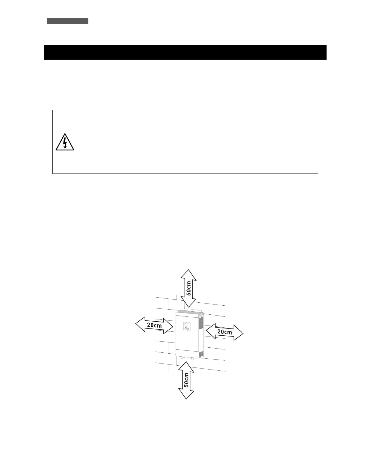
4. During normal operation the ATA discharges a minimal amount of heat. So it is necessary to leave at least 20
cm of unobstructed space on the side and 50 cm up and down of ATA in order to keep it properly ventilated.
Page 11
ENGLISH
ATA Energy Storage System MM 5 User’s manual
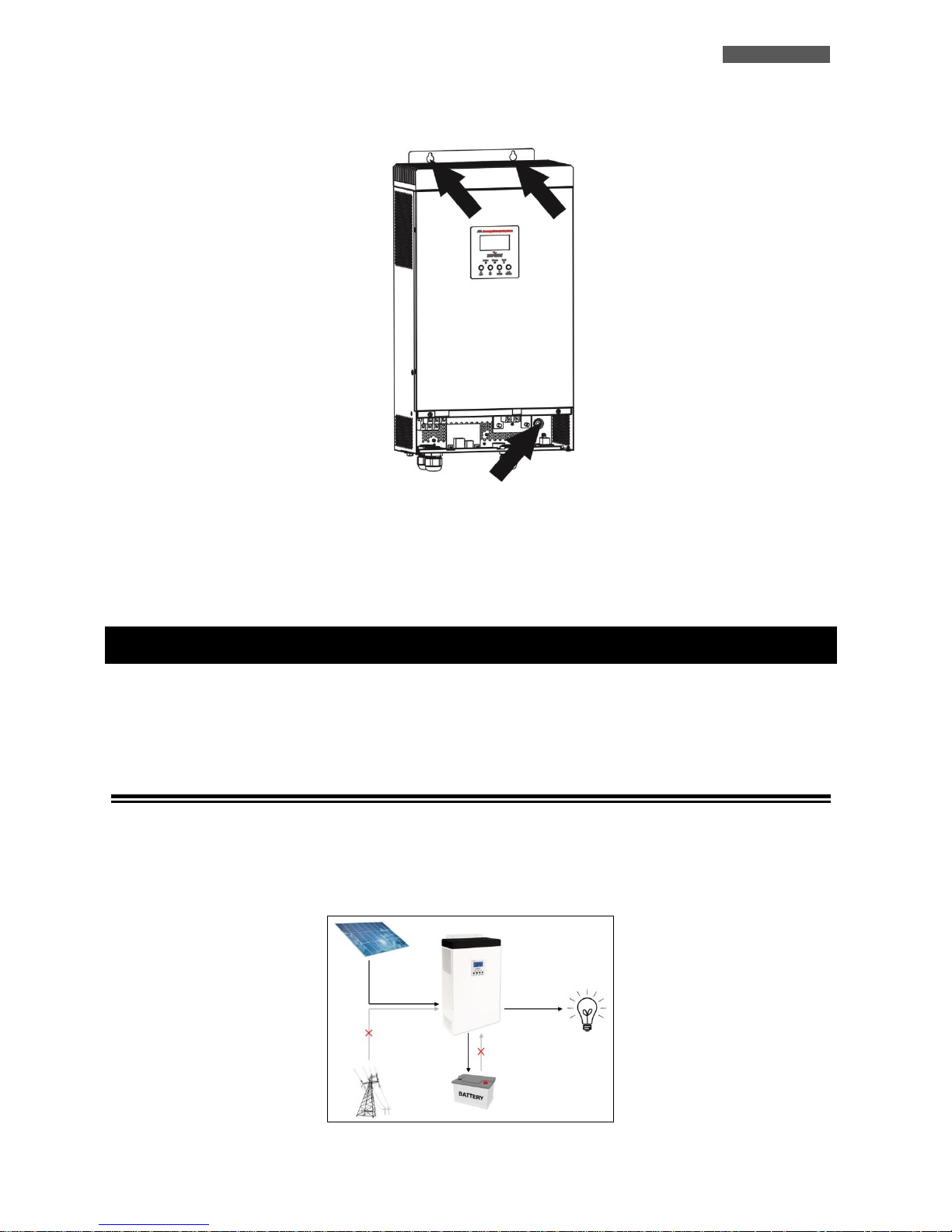
5. Fix ATA on the choice surface, through the use of screws and dowels. See the image below for the fixing point
on the ATA.
6. Do not obstruct ventilation holes.
7. Do not insert objects or pour liquids in the ventilation holes.
8. Do not rest any object on top of the ATA.
9. Do not keep liquids, flammable gases or corrosive substances near the unit.
4 Operating
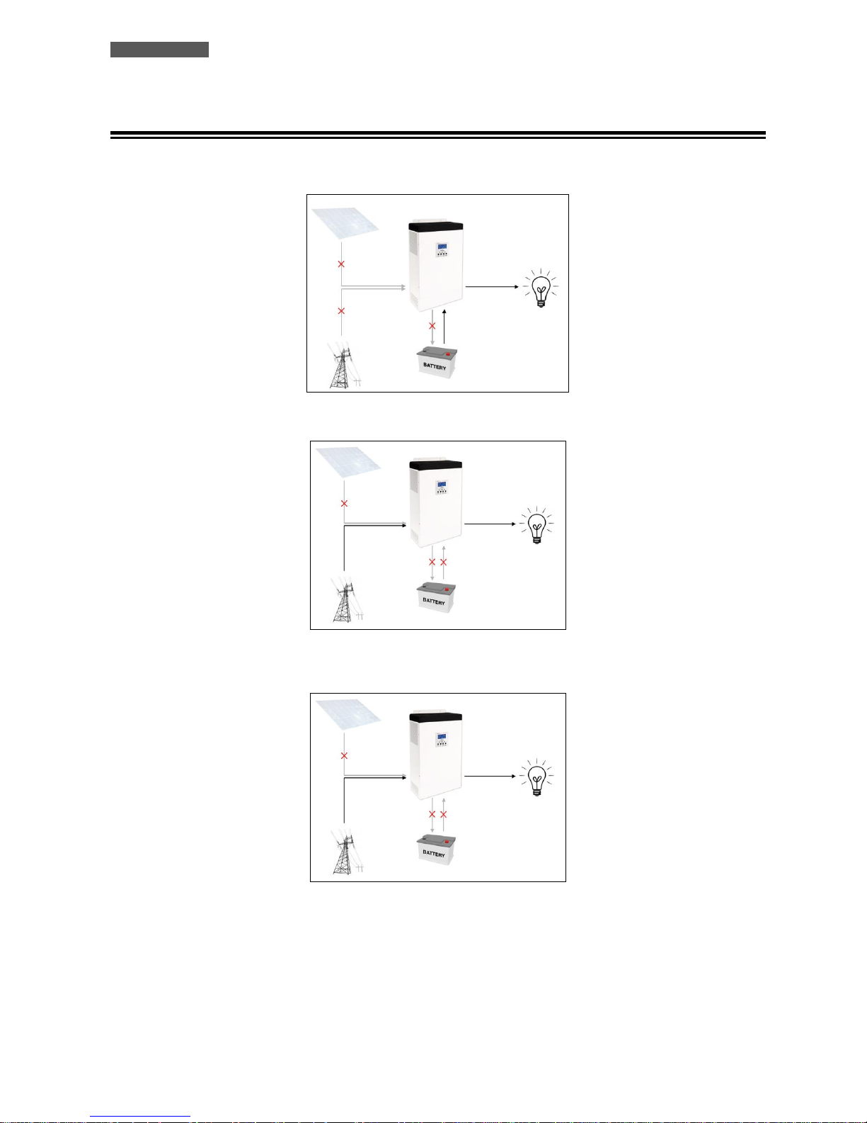
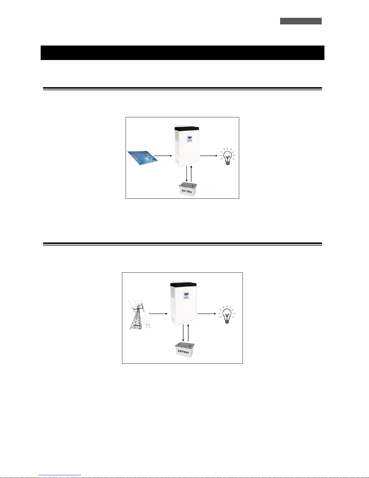
The typical mode of operation is the SBU mode: the acronym SBU indicates the order of priority of the power supply
used by ATA. The first source is S = SOLAR, i.e. solar panels; the second source is B = BATTERY, i.e. batteries; the third
source is U = UTILITY, i.e. the AC Utility Line.
4.1 Functioning with active PV panels
The equipment is powered by the ATA system by using the energy from the PhotoVoltaic (PV) panels. During this
phase, the ATA simultaneously charges the batteries and works independently without any need to use the mains. ATA
is equipped with a MMPT system (Maximum Power Point Tracker) that allows to find the best workable point to
maximize the power of solar panels, depending to the solar irradiation that they are exposed.
Page 12
ENGLISH
User’s manual 6 ATA Energy Storage System MM
4.2 Functioning with inactive PV panels
The equipment is powered by the ATA system by using the energy stored in the batteries until the photovoltaic panels
are once again active. The stored energy can be used up to a minimum threshold of 30/40% (settable in settings).
Only in the case of this energy not being sufficient will the equipment be powered automatically from the mains.
Should a blackout occur during this phase, the ATA uses the 30/40% of energy remaining in the batteries (UPS function)
to power the equipment.
Once the residual energy has been used up, the system turns off. When the mains or the photovoltaic panels are
reactivated, the ATA Energy Storage System automatically starts up again.
When the battery charger level reaches the threshold value set, ATA Energy Storage System automatically switches to
active panels mode (see section 4.1).
Page 13
ENGLISH
ATA Energy Storage System MM 7 User’s manual
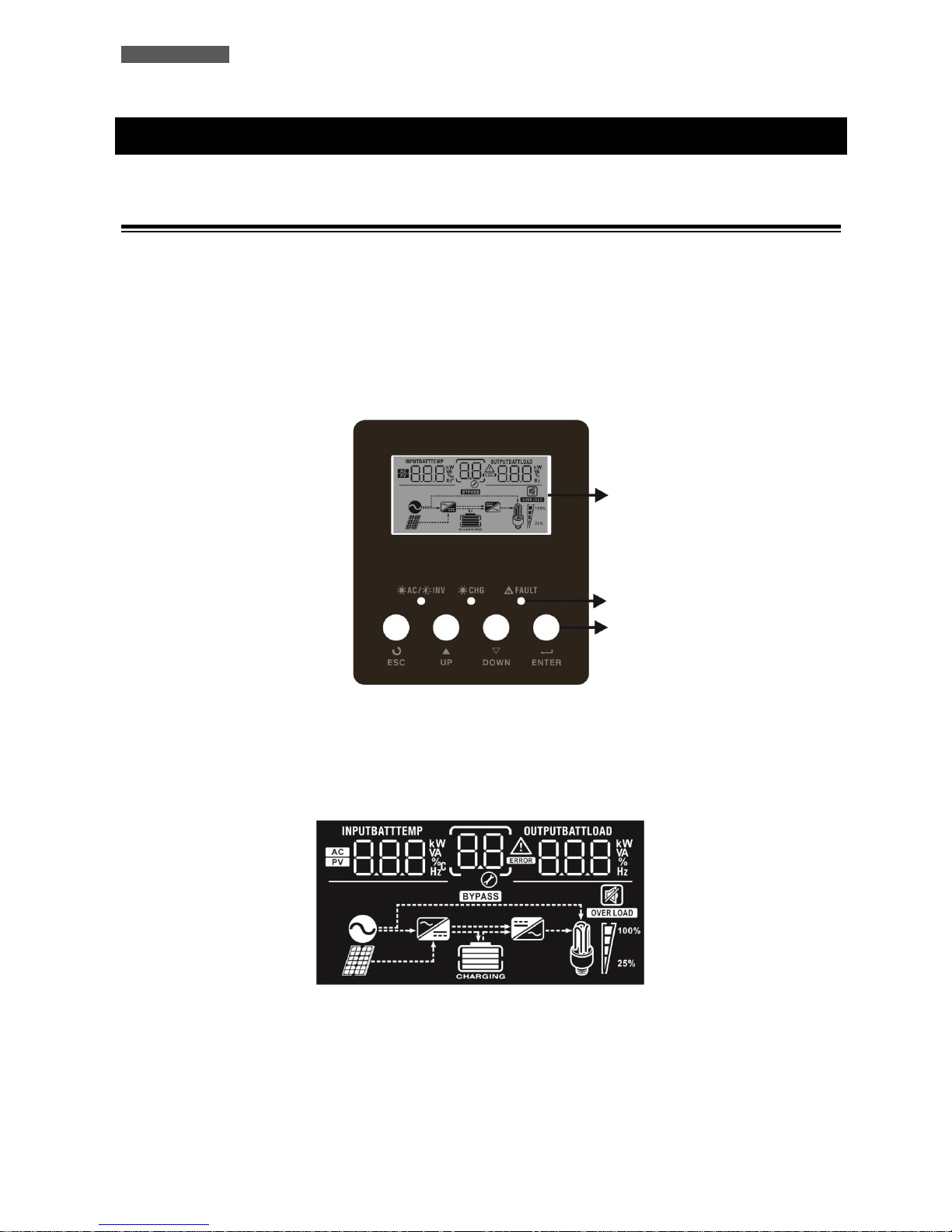
5 Other Operating Modes
5.1 Only with PV panels
ATA system use the PhotoVoltaic (PV) Panels energy to power the equipment; simultaneously charges the batteries. In
the case the photovoltaic panels energy is not sufficient ATA use the batteries energy.
To active this modality you need to set correctly the parameters 01 and 16 in the ATA settings. See the chapter
“Settings”.
5.2 Only with the main (UPS)
ATA system use the mains to power the equipment; simultaneously charges the batteries. In the case the mains is not
available ATA use the batteries energy.
To active this modality you need to set correctly the parameters 01 and 16 in the ATA settings. See the chapter
“Settings”.
Page 14
ENGLISH
User’s manual 8 ATA Energy Storage System MM
6 External Description
6.1 Front Panel
The front panel informs the user about operating status, alarm conditions and measurements. It also provides access to
controls and configuration parameters.
Front panel shown below consists of two parts:
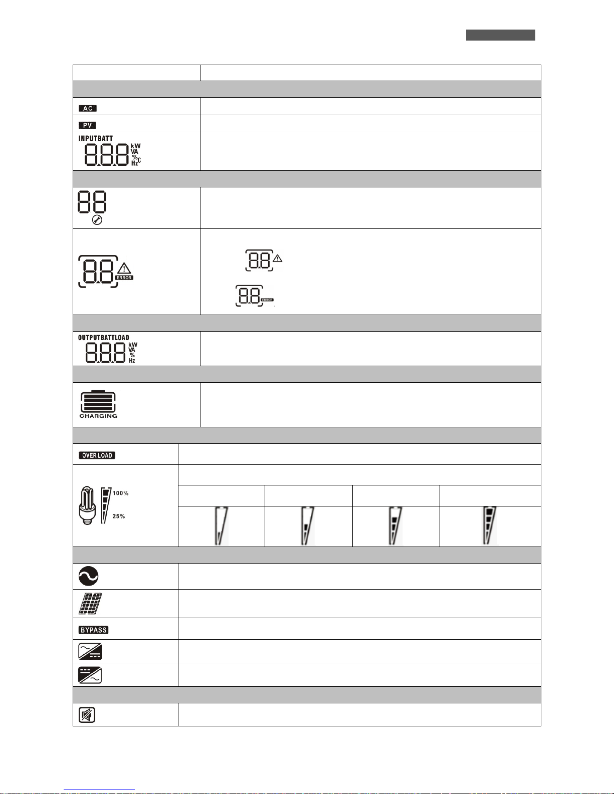
1. Graphic LCD panel provides complete information about the functioning status and existing alarms, Load and
Battery level, Input, Output and Battery measurements.
2. 4 buttons enables the user to turn ON/OFF the ATA and to make selections of the functioning parameters.
Figure 1 – Front panel
6.1.1 Graphic LCD Panel
Please refer to figure 2.
Figure 2 – Graphic LCD Panel
LCD display
LED
Buttons
Page 15
ENGLISH
ATA Energy Storage System MM 9 User’s manual
LCD Icon
Function Description
Input Source Information
Indicates the AC input.
Indicates the PV input
Indicates input voltage, input frequency, PV voltage, battery voltage and charger
current.
Configuration Program and Fault Information
Indicates the setting program.
Indicates the warning and fault codes.
Warning: flashing with warning code.
Fault: lighting with fault code
Output Information
Indicate output voltage, output frequency, load percent, load in VA and load in
Watt.
Battery Information
Indicates battery level by 0-24%, 25-49%, 50-74% and 75-100% in battery mode and
charging status in line mode.
Load Information
Indicates overload.
Indicates the load level by 0-24%, 25-50%, 50-74% and 75-100%.
0%~25%
25%~50%
50%~75%
75%~100%
Mode Operation Information
Indicates unit connects to the mains.
Indicates unit connects to the PV panel.
Indicates load is supplied by utility power.
Indicates the utility charger circuit is working.
Indicates the DC/AC inverter circuit is working.
Mute Operation
Indicates unit alarm is disabled.
Page 16
ENGLISH
User’s manual 10 ATA Energy Storage System MM
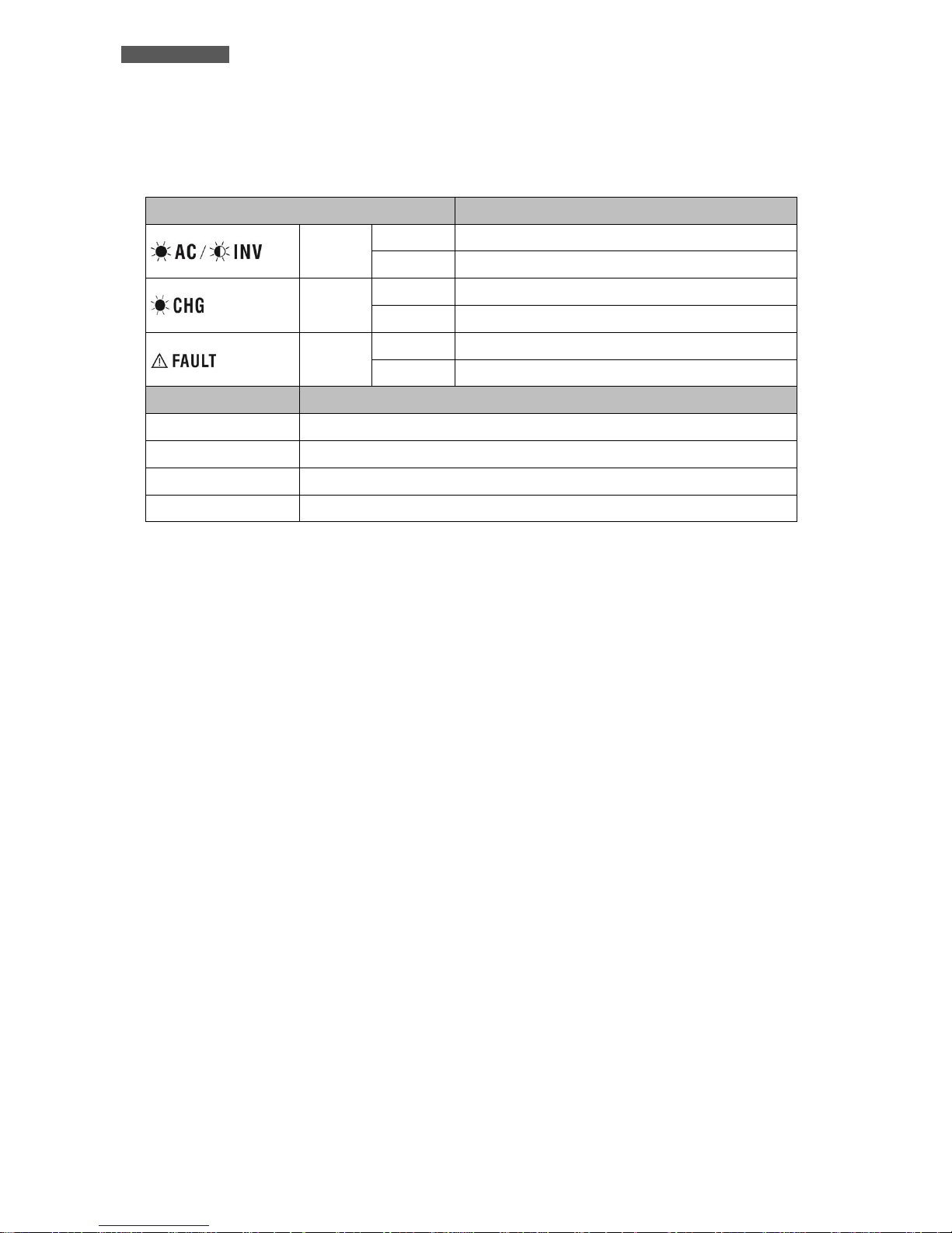
6.1.2 Led Indicator and Buttons
Functions of the buttons are given below:
LED Indicator
Messages
Blu
Solid On
Output is powered by utility in Line mode.
Flashing
Output is powered by battery or PV in battery mode.
Blu
Solid On
Battery is fully charged.
Flashing
Battery is charging.
Red
Solid On
Fault occurs in the inverter.
Flashing
Warning condition occurs in the inverter.
Button
Description
ESC
To exit setting mode
UP
To go to previous selection
DOWN
To go to next selection
ENTER
To confirm the selection in setting mode or enter setting mode
Page 17
ENGLISH
ATA Energy Storage System MM 11 User’s manual
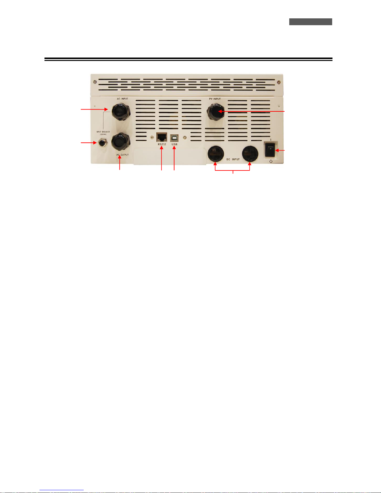
6.2 Rear Side
Figure 3 – Rear Side
1. Power On/Off Switch: to turn on or turn off the ATA
2. Grounded AC Input: to connect the ATA to the AC utility line.
3. PV Input: to connect the ATA to the PV panels.
4. Battery Input: to connect the ATA to the batteries.
5. Input Circuit Breaker: it goes off in Overload or short-circuit condition; push the external button of the Circuit
Breaker to reactivate it.
6. Grounded AC Output: to supply loads.
7. Computer Interface (RJ45/RS232 connector): it is the communication RJ45/RS232 port (through the cable RJ45-
RS232).
8. Computer Interface (USB connector): it is the communication USB port.
1
2
3
5 6 4 7 8
Page 18
ENGLISH
User’s manual 12 ATA Energy Storage System MM
7 Electrical Installation
The electrical installation has to be done by qualified personnel. Follow all the Safety
Standards (CEI Standards in Italy or IEEE elsewhere) for the Input/Output connections
and for the right selection of Input/Output cables.
For safety we recommend using external circuit breaker between AC Mains line and
ATA Input line: the circuit breaker should be qualified as RCCB (Residual Current
Circuit Breaker RCCB) with leakage current protective function (leakage current < 300
mA).
For safety we recommend using external circuit breakers between ATA Output line
and the loads: the circuit breakers should be qualified as RCCB (Residual Current
Circuit Breaker RCCB) with leakage current protective function (leakage current < 30
mA).
It is also advisable to install a PV protection system between the PV panels line and the
PV panels Input of ATA, dimensioned according to the installed PV panels.
ATTENTION: for safety and efficiency it is recommended to use always cables with the
cross section equal or thicker than the specified one into the following table.
TECNOWARE declines any responsibility if these warnings are disregarded.
The ATA models have inside the case only the electronic parts: the batteries are installed externally.
Before starting the installation procedure, be sure that:
1. The AC Utility Line for the ATA has been removed, the PhotoVoltaic (PV) panels
and the batteries pack are disabled.
2. The ATA is completely OFF (only if graphic LCD panel is OFF).
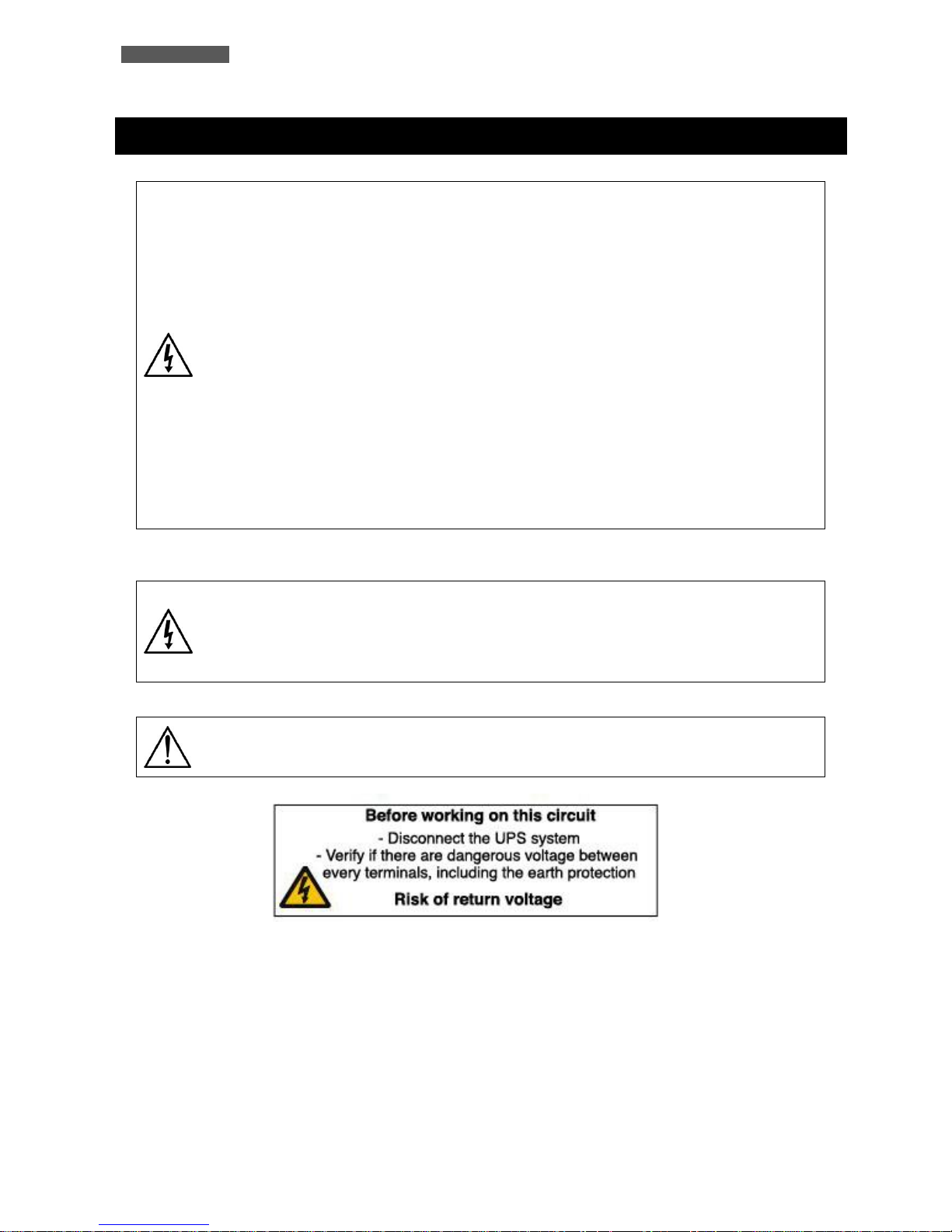
Is necessary to apply a label, as the following one, into the AC input and output
distribution box.
Page 19
ENGLISH
ATA Energy Storage System MM 13 User’s manual
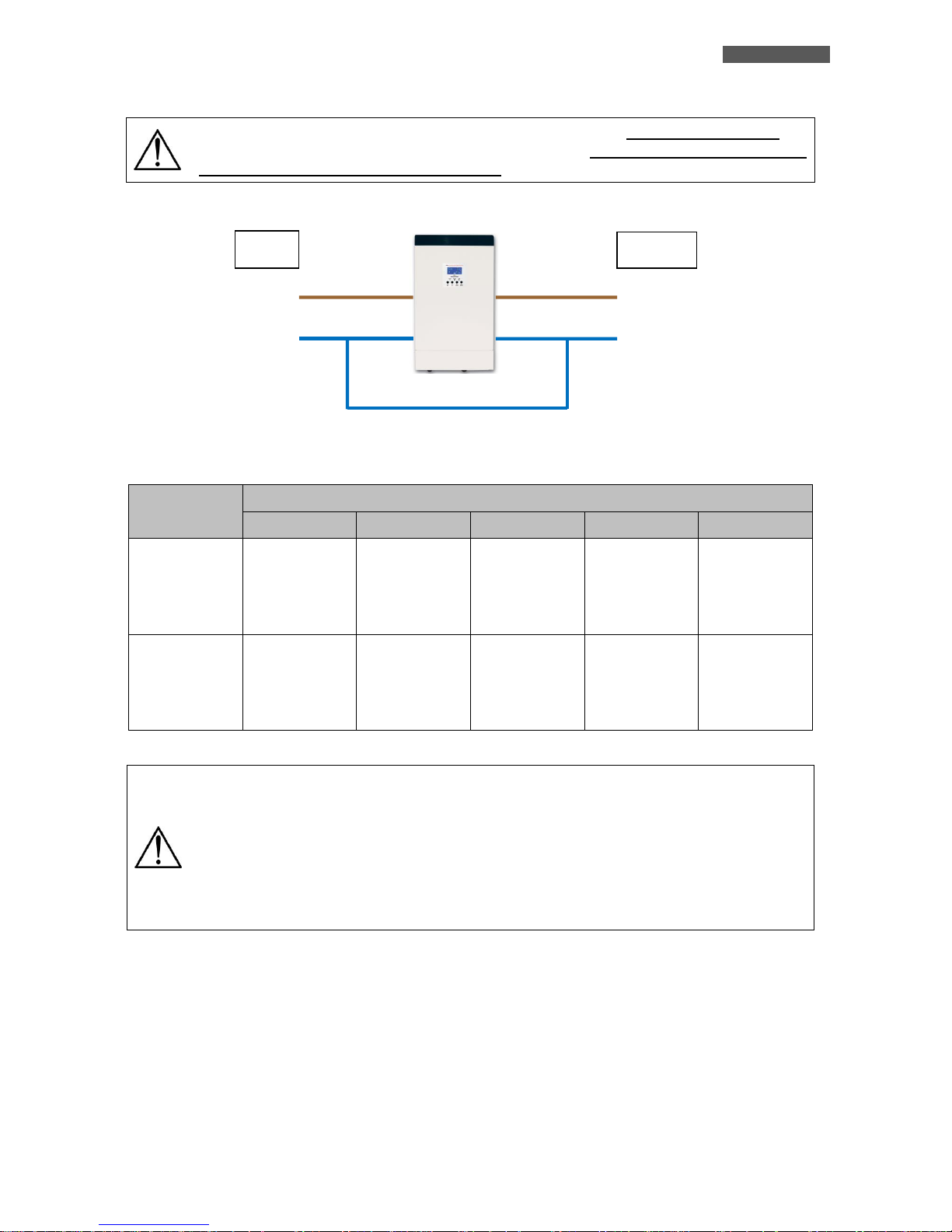
When ATA works with the PV panels and/or the batteries the Neutral is not through. To
recreate the same input supply system (AC input main), the neutral line of output must
be connected with the neutral line of input. See the image below.
The following table shows the recommended size for wires.
Model
Wiring spec (cross section mm2 - AWG)
Input
PV panels
Batteries
Output
Ground
ATA 4.0 MM
6 mm
2
or
10 AWG
8 mm
2
or
8 AWG
2 x 8 mm2
or 2 x 8 AWG
(2 cables together
with a single
cable lugs)
6 mm2 or
10 AWG
6 mm2 or
10 AWG
ATA 5.0 MM
8 mm
2
or
8 AWG
8 mm
2
or
8 AWG
2 x 8 mm2
or 2 x 8 AWG
(2 cables together
with a single
cable lugs)
8 mm
2
or
8 AWG
8 mm2 or
8 AWG
The wires for ATA 4.0 MM must be designed to withstand currents up to 29A if using
for AC Utility Line, up to 60A (PV panels), up to 75A (Batteries) and up to 18A (Output
Line). For security and reliability you need to use cables with a cross section not less
than those indicated in the table above.
The wires for ATA 5.0 MM must be designed to withstand currents up to 29A if using
for AC Utility Line, up to 60A (PV panels), up to 93A (Batteries), and up to 22A (Output
Line). For security and reliability you need to use cables with a cross section not less
than those indicated in the table above.
INPUT
OUTPUT
LINE
LINE
NEUTRAL
NEUTRAL
Page 20
ENGLISH
User’s manual 14 ATA Energy Storage System MM
7.1 Installation
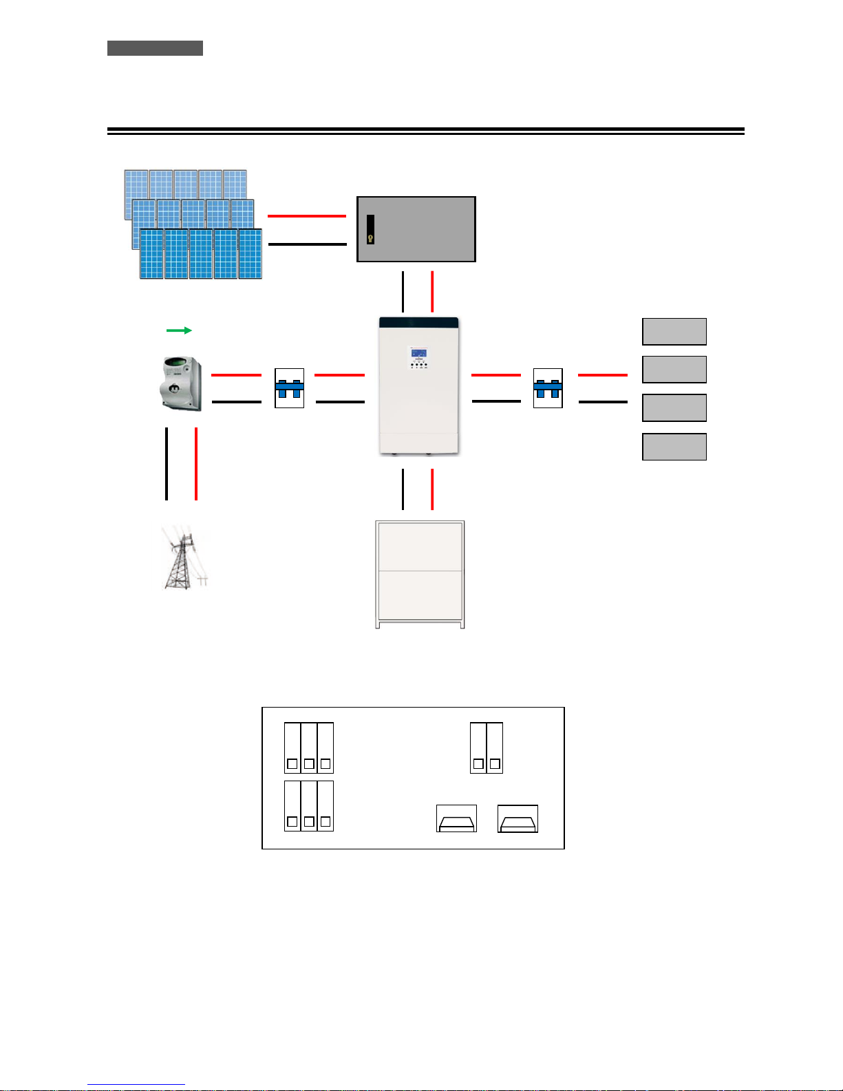
Figura 4 – ATA installation and connection
ON
OFF
ON
OFF
LOAD
RCCB
(Residual Current
Circuit Breaker)
30mA (existing)
RCCB
(Residual Current
Circuit Breaker)
ELECTRICITY
METER (existing)
PV PROTECTION
SYSTEM
PV PANELS
ATA ENERGY
STORAGE SYSTEM
BOX BATTERIE ATA
AC MAINS LINE
ATA CONNECTIONS
+ BATTERY
- BATTERY
G L N
G L N
AC MAINS INPUT
OUTPUT
PV PANELS INPUT
PV+
PV-
Page 21
ENGLISH
ATA Energy Storage System MM 15 User’s manual
We advise you to follow the steps below explained:
1. Connect the ATA Input line to the AC mains line (see figure 4). It is mandatory to ground the AC mains line
according to the Safety Standards. Carefully check the grounding of AC mains line. For safety we recommend to
install an external circuit breaker (RCCB type, with leakage current < 300 mA) between AC mains line and ATA
Input line (see figure 4).
2. Connect the line of the PhotoVoltaic panels to the ATA units (see Figure 4). Pay attention to connect the panels
in such a way as to meet the specifications (see the chapter "Technical Specifications").
2.1 Each series of panels shall not exceed the maximum open circuit voltage of 145 Voc.
2.2 The peak power supplied by PhotoVoltaic panels is 3750 Wp.
2.3 Therefore, we assume the use of 250 Wp panels with a rated voltage of 37.7 Vdc, it will be possible to build
a system like the following:
2.3.1 Using PhotoVoltaic panels with a nominal voltage of 37.7 Vdc, it will be able to achieve a serie of panels
(named string) with up to 3 panels because:
3 x 37,7 = 113,1Vdc, that is less than the maximum open circuit voltage of 145 VOC.
2.3.2 Using PhotoVoltaic panels with a power of 250 Wp, it will be able to achieve up to 5 strings of panels
connected in parallel because:
The peak power of each string = 3 x 250 = 750 Wp (number of panels in a string multiplied by the peak
power of each panel).
The peak power of the system = 5 x 750 = 3750 Wp (number of strings multiplied by the peak power of
each string).
2.4 It is also advisable to install a PV protection system between the PV panels line and the PV panels Input of
ATA, dimensioned according to the installed PV panels
3. Connect the devices to be supplied to the ATA outputs. Be sure all the devices have the main switch in OFF
position. For safety we recommend to install an external circuit breaker (RCCB type, with leakage current < 30
mA) between ATA Output line and the loads (see figure 4).
4. Connect ATA to the external Battery Box:
We suggest to use ONLY Battery Box supplied by TECNOWARE. TECNOWARE declines
any responsibilities if this rule is not followed.
Before starting whichever operation be sure that the Battery circuit breaker of Battery
Box is in “OFF” position.
4.1 The ATA unit is designed to operate with a nominal voltage from batteries equal to 48 Vdc (4 x 12Vdc).
4.2 After connecting the battery (follow the instructions of battery box user manual), check the right polarity
and the total voltage of the battery pack.
4.3 Connect the box battery to the ATA, via the cables supplied with the battery box.
Page 22
ENGLISH
User’s manual 16 ATA Energy Storage System MM
It is compulsory to ground the ATA according to the Safety Standards.
The case of the ATA is internally connected to the ground terminal (GND) of the
IN/OUT terminals, in order to guarantee safety to the user. To guarantee safety it is
necessary to be sure that the local electric plant is supplied with GROUND (in
compliance with the Safety Standards), and that a valid connection is guaranteed
between the GROUND of the UPS and the GROUND of the local electric plant.
Any interruption of the GROUND conductor is absolutely prohibited.
Risk of electric shock at the Output lines if the ATA is ON, even when the ATA is not
connected to AC utility line.
Risk of electric shock at the Output lines while the unit is connected to the AC utility
line.
Risk of electric shock: do not remove the cover. The ATA contains internal parts which
are at a high Voltage and are potentially dangerous, capable of causing injury or death
by electric shock.
There are no internal parts in the ATA which are user serviceable. Any repair or
maintenance work must be performed exclusively by qualified technical personnel
authorized by TECNOWARE. TECNOWARE declines any responsibility if this warning is
disregarded.
Disregard for these warnings may lead to a risk of electric shock to operators.
8 First Start Up
Turning the ATA is very easy. Nevertheless we recommend that, on First Start Up, the following procedure is
observed for greater safety.
1. Be sure the circuit breaker of ATA outputs is in “OFF” position.
2. Place the circuit breaker of external batteries in “ON” position.
3. Place the circuit breakers of PV panels in “ON” position.
4. Place the AC Input line circuit breaker of ATA in “ON” position.
5. As a consequence of point 4, the ATA turns on the graphic display and goes in Stand-by mode: the ATA doesn’t
supply Output power and recharges only the batteries in accordance with SBU mode.
6. Place the On/Off switch of the ATA in “ON” position: the ATA emits a brief acoustic signal and performs a
functioning SELF-TEST. After some seconds the ATA starts to work in SBU mode and the graphic LCD panel will
show the path of energy.
7. Place the circuit breaker of ATA outputs is in “ON” position. Then turn ON the devices (one by one) to be supplied
by ATA, checking the ATA doesn’t report Overload information on the graphic LCD panel and all the devices are
working regularly.
Page 23
ENGLISH
ATA Energy Storage System MM 17 User’s manual
9 Functioning
9.1 Turning ON and OFF
To turn completely ON the ATA please do the following steps:
Place the circuit breaker of external batteries in “ON” position.
Place the circuit breakers of PV panels in “ON” position.
Place the AC Input line circuit breaker of ATA in “ON” position.
Place the On/Off switch of the ATA in “ON” position.
The graphic LCD panel provides complete information about the functioning status.
To turn completely OFF the ATA please do the following steps:
Place the On/Off switch of the ATA in “OFF” position: the ATA switches in Stand-
by mode.
Place the AC Input line circuit breaker of ATA in “OFF” position.
Place the circuit breaker of external batteries in “OFF” position.
Place the circuit breakers of PV panels in “OFF” position.
The graphic LCD panel and the leds on the front panel are OFF only when the UPS is
completely OFF.
The ATA can be turned on even in the absence of production from PV panels and in the absence of AC mains.
9.2 Low Battery and Automatic Restart
The ATA reaches the Low Battery condition whenever the batteries reach a charge level allowing the connected
devices to operate for few minutes (about 10% of max charge), following its use without other sources of energy (AC
mains is not available, and the production from PV panels is off).
The UPS warns operators of Low Battery by lighting of the LOW BATT. icon on the graphic LCD.
If the AC mains (or the production from the PV panels) is not restored within a few minutes, the UPS shuts-down
automatically thus preventing the batteries from discharging excessively; the ATA stops supplying Output power,
deactivates control panel indication and goes to a waiting state. Once AC mains (or the production from the PV panels)
is comes back on, the ATA restarts automatically and after some seconds it goes back to work in SBU mode.
The battery charging takes place only when the voltage from the PV panels is present and sufficient.
Page 24
ENGLISH
User’s manual 18 ATA Energy Storage System MM
9.3 Load Testing
The UPS indicates the Output Load level by graphic LCD (as described in the chapter 5).
When the Output load is higher then nominal value the ATA warns of Overload condition by graphic LCD and by
acoustic alarm as described in the “Warning Table” and in the “Troubleshooting” chapter.
The UPS has the capability to accept an Overload less than 110% for 10 minutes.
An Overload between 110% and 150% is accepted for about 10 seconds and after ATA switches automatically to the
Bypass mode.
An Overload between 150% and 200% is accepted for about 5 seconds and after ATA switches automatically to the
Bypass mode..
Once the requested power is back within range, the ATA switches automatically to the SBU mode.
Make sure that the ATA never indicates Overload condition.
Do not connect a load greater than rated value to the ATA (see POWER specifications
in the chapter “Technical Characteristics”), as this may damage the unit. In this case
the warranty is void.
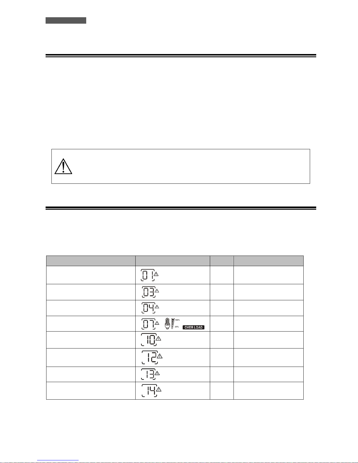
9.4 Operation in Warning Status
During a warning condition the buzzer beeps, it means that there are some problems for ATA operation. Users can get
the Fault code from graphic LCD panel. Please check the “Troubleshooting” chapter for details.
Below you can see the “Warning Table”, with the correspondence between each warning and the relative signals
(icons on graphic LCD and acoustic alarm) for the user.
WARNING
ICON (flashing)
CODE
ACOUSTIC ALARM
Fan is locked when inverter is on.
01
Beep three times every
second
Battery is over-charged
03
Beep once every second
Low battery
04
Beep once every second
Overload
07
Beep once every 0.5 second
Output power derating
10
Beep twice every 3 seconds
Solar charger stops due to low
battery.
12
Solar charger stops due to high PV
voltage.
13
Solar charger stops due to
overload.
14
Warning Table
Page 25
ENGLISH
ATA Energy Storage System MM 19 User’s manual
9.5 Operation in Fault Mode
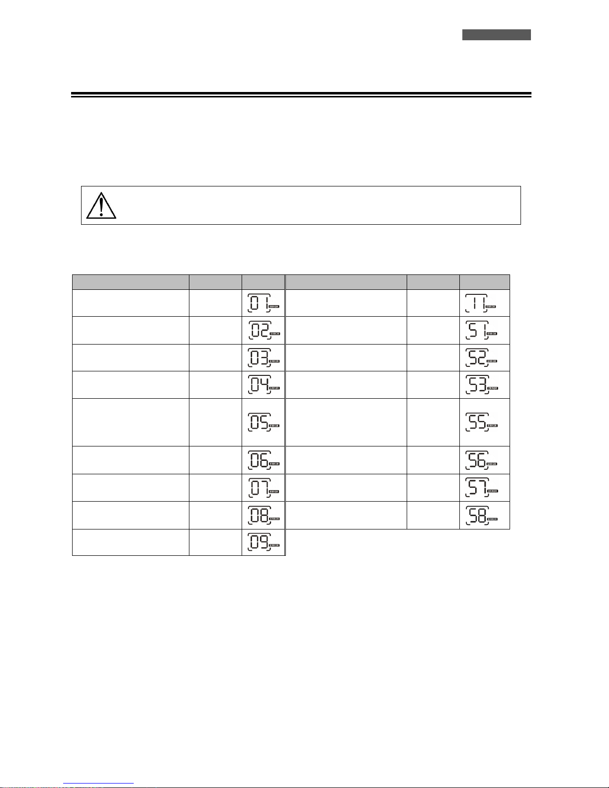
When Fault led illuminates and the buzzer beeps continuously, it means that there is a fatal error in the ATA. Users
can get the Fault code from display panel. Please check the “Troubleshooting” chapter for details.
Please check the loads, wiring, ventilation, mains supply, PC supply, Battery and so on after the fault occurs. Don’t try
to turn ON the ATA again before solving the problems. If the problems can’t be fixed, please contact Technical Service
immediately.
In case of emergency, please disconnect the connection from mains supply, PV supply,
external Battery, and Output immediately to avoid further risk or danger.
Below you can see the “Fault Table”, with each Fault event and the relative FAULT code/icon on graphic LCD for the
user’s information.
FAULT EVENT
FAULT CODE
ICON
FAULT EVENT
FAULT CODE
ICON
Fan is locked when inverter
is off.
01
Main relay failed
11
Over temperature
02
Over current or surge
51
Battery voltage is too high
03
Bus voltage is too low
52
Battery voltage is too low
04
Inverter soft start failed
53
Output short circuited or
over temperature is
detected by internal
converter components.
05
Over DC voltage in AC output
55
Output voltage is too high.
06
Battery connection is open
56
Overload time out
07
Current sensor failed
57
Bus voltage is too high
08
Output voltage is too low
58
Bus soft start failed
09
Fault Table
Page 26
ENGLISH
User’s manual 20 ATA Energy Storage System MM
10 Communication Interfaces
The ATA unit is factory-equipped with RJ45/RS232 and USB Communication Interfaces, usable as communication ports
with a Personal Computer.
Only one of the RS232/USB communications can be activated at one time. To activate RJ45/RS232 communication it
is sufficient to connect the RJ45/RS232 cable only; to activate USB communication it is sufficient to connect the USB
cable only.
The RJ45/RS232 and USB interface signals are isolated through photo-couplers.
Connecting to the Web site www.tecnoware.com it is possible to download free of charge the updated Management
Software for ATA, named WatchPower, compatible with the most popular Operating Systems.
It is possible to add an Interface RS485 (optional).
10.1 WatchPower
The management software WatchPower allows to monitor the operation of the system, to monitor the electrical
variables (current from PV panels, current from batteries, battery capacity, power output, working frequency and
other variables), to set the ATA functioning parameters, to record the data generated by the system, to see the
graphical representation of recorded data in function of time, and to extrapolate these data to an Excel file. You can
also set the alert by mail of any anomalies detected by the system.
In order to change the settings of the system is required to login as administrator. The default password is
"administrator". It is possible to change the password after the first login with the default password.
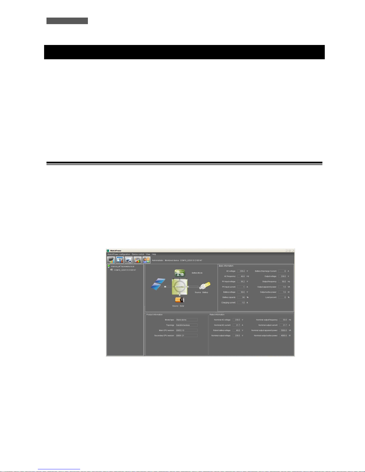
10.1.1 System Monitoring
From the above screen, you can display the values of the system. The diagram shows which parts of the system
are active.
The values of the operation of the system are displayed in real time and indicate the voltage and input
frequency, the voltage and the current generated by the PV panels, the voltage, the capacity, the charging and
discharging current of the batteries (when supplying energy to the load ) , the voltage and frequency output
and information related to the absorption of the connected devices (active and apparent power and its
percentage).
Page 27
ENGLISH
ATA Energy Storage System MM 21 User’s manual
10.1.2 Setting the operating parameters of ATA
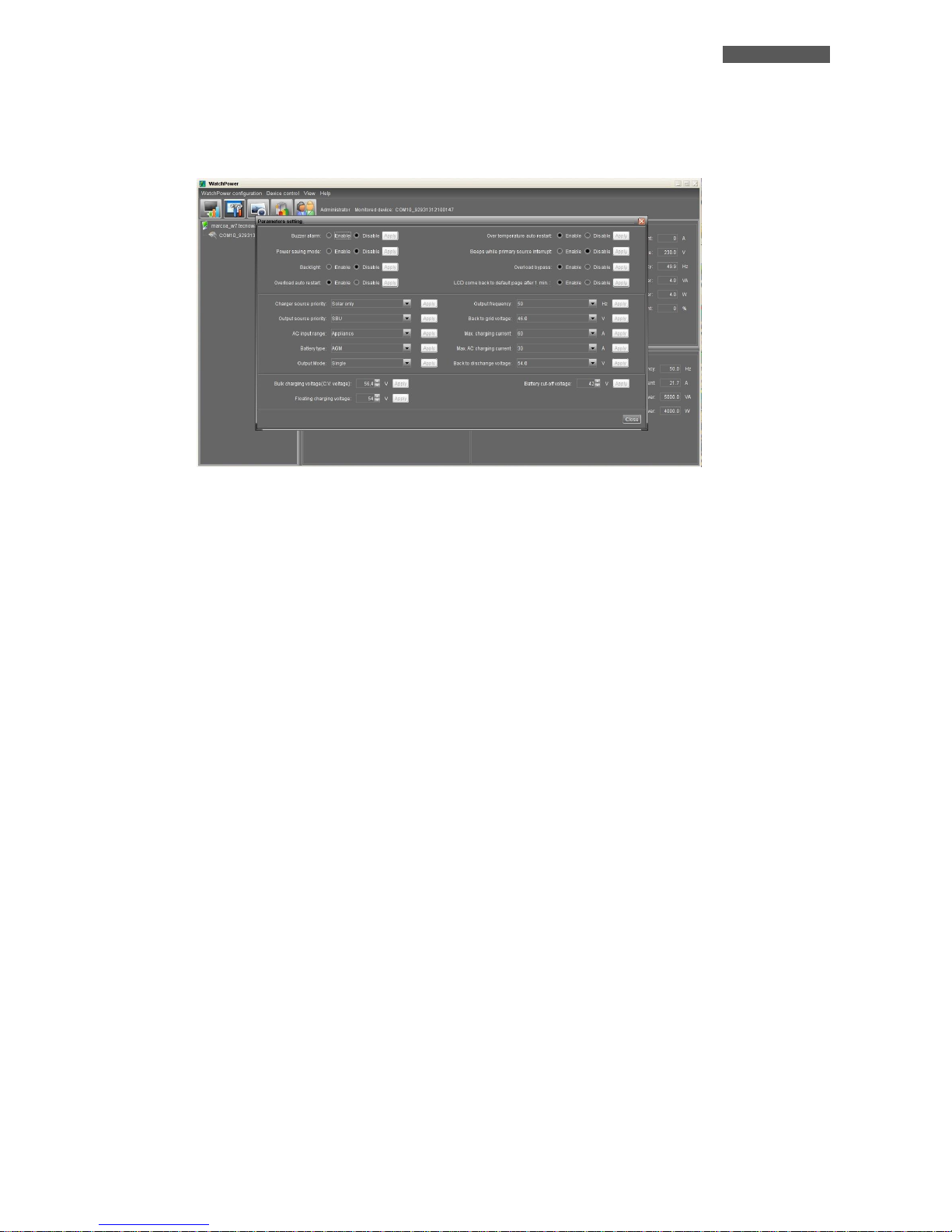
By clicking on the "Parameters Setting", you can select the same settings that can be set by the front panel.
These settings affect the operation of the entire system. And it is possible to enable or disable alarms and
functions (acoustic alarm, warning in the absence of AC mains line, power saving mode, backlight, reboot in
case of overload and/or bypass, etc ...), to select the functioning mode (SBU, Utility, etc ... ), to select the
priority of power for the loads (only by solar panels, only by AC Utility Line, hybrid between AC Utility Line and
PV panels), to select the operating parameters of the batteries (maximum voltage charging, charging current,
maintenance voltage, minimum voltage of work for which the system then feeds the loads by AC Utility Line)
and to select parallel or three-phase mode.
To apply any changes you need to login as administrator. It is advisable to make such changes to qualified
personnel.
Page 28
ENGLISH
User’s manual 22 ATA Energy Storage System MM
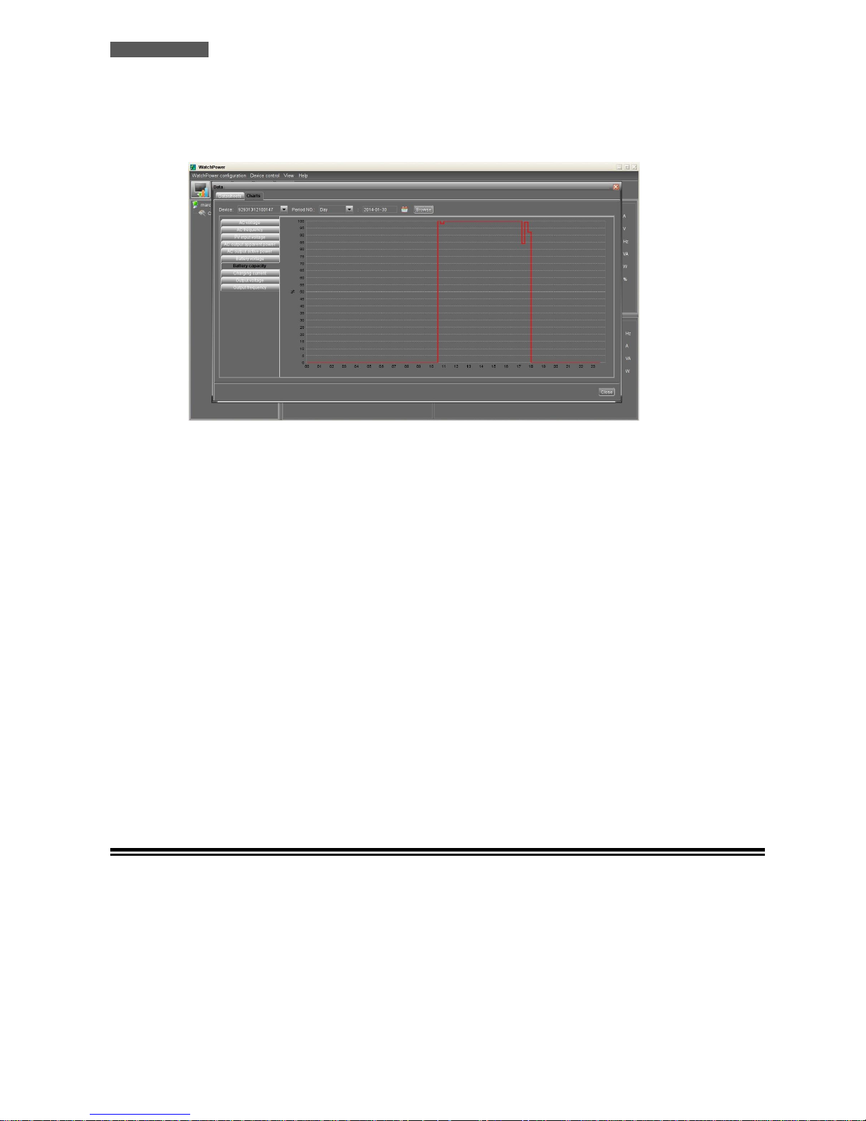
10.1.3 Recording and graphical representation of the values of the System
ATA has a system of storing the historical operation values. It is possible to view these values graphically or
extrapolate on Excel file. You can access the historical clicking on the "Data" button.
In the graphic representation, you can select the type of parameter to be displayed going to perform filtering
on the time in which you are interested. This filtering can be done by hour, day, month and year.
The same type of filtering (by hour, day, month and year) may be carried out for the data to extrapolate on
Excel file.
10.1.4 Other Functions
The program allows you to use other functions such as sending e-mail messages, changing the default password,
setting the update times, storing the values of the system, and selecting, historicizing and extrapolating the
anomalies to an Excel file.
By accessing the menu "WatchPower Configuration" you can set the sending of e-mail messages, by configuring
your mail server to use, email recipients and the events that cause the e-mail messages.
By clicking on the "Event Log" you can set the filtering (by hour, day, month and year) of the anomalies found
during the operation of the system and set the view or extrapolation on an Excel file.
By clicking on the "Basic" you can set the time to update the values produced by the system in real time,
recording interval of those values and the date format that appears.
10.2 RS485 Interface
You can use an RS485 Interface to make compliant the ATA unit with the RS485 communication Standard. The RS485
Interface is optional.
Page 29
ENGLISH
ATA Energy Storage System MM 23 User’s manual
11 Parallel System Connection
11.1 Introduction
Maximum of 4 pcs of identical power and specification ATA can be connected in parallel: so the max handling power is
20KVA/16KW (for ATA 5.0 MM).
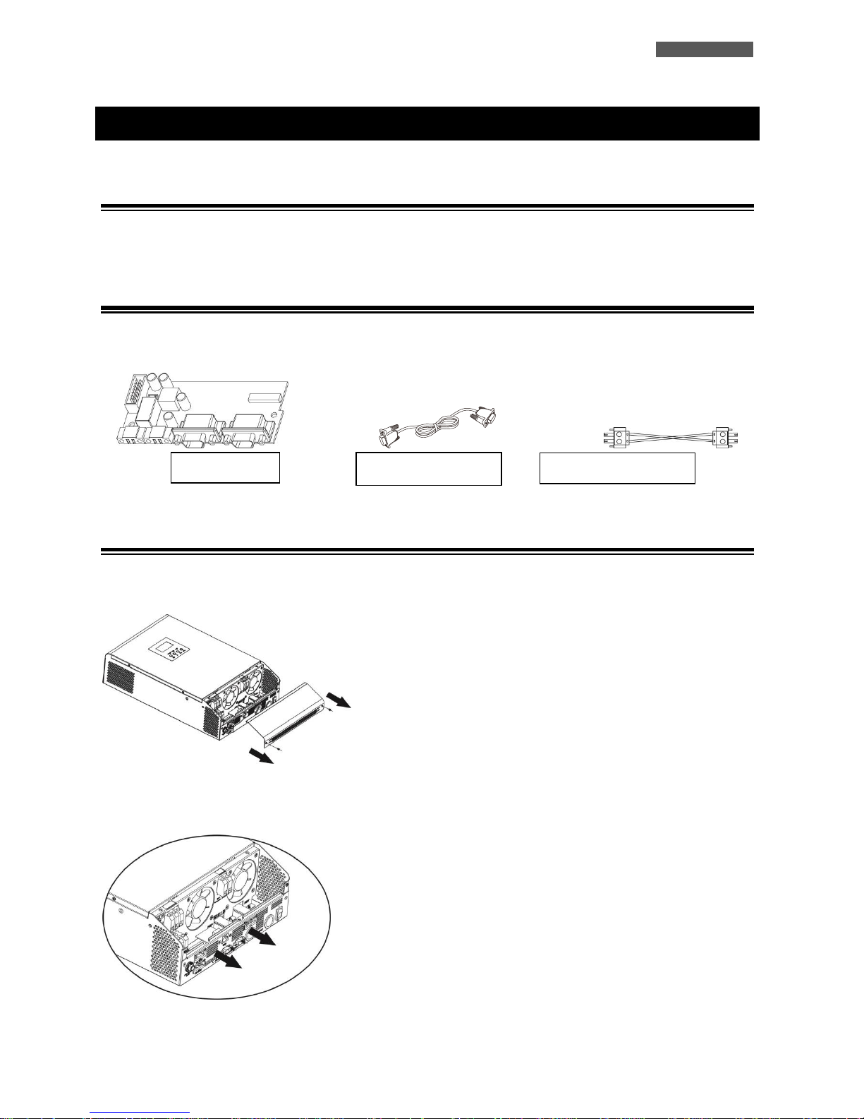
11.2 Parallel Kit
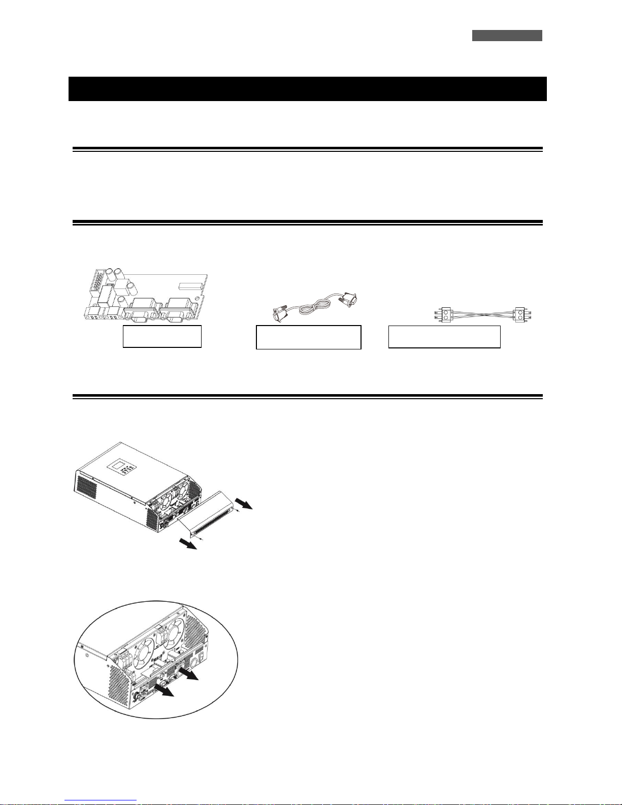
The parallel kit consists of:
11.3 Parallel Kit Installation
1. Remove the metal cover, see the following figure.
2. Remove the Communication Board (with RJ45 and USB port).
Parallel Board
Parallel Cable
Sharing Current Cable
Page 30
ENGLISH
User’s manual 24 ATA Energy Storage System MM
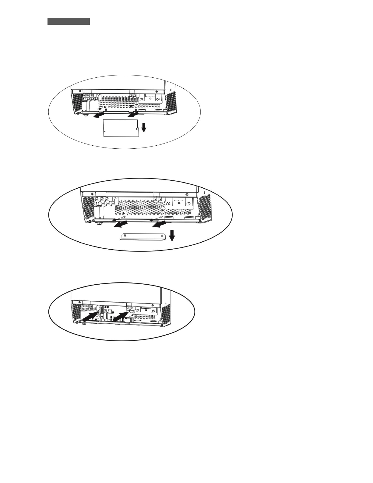
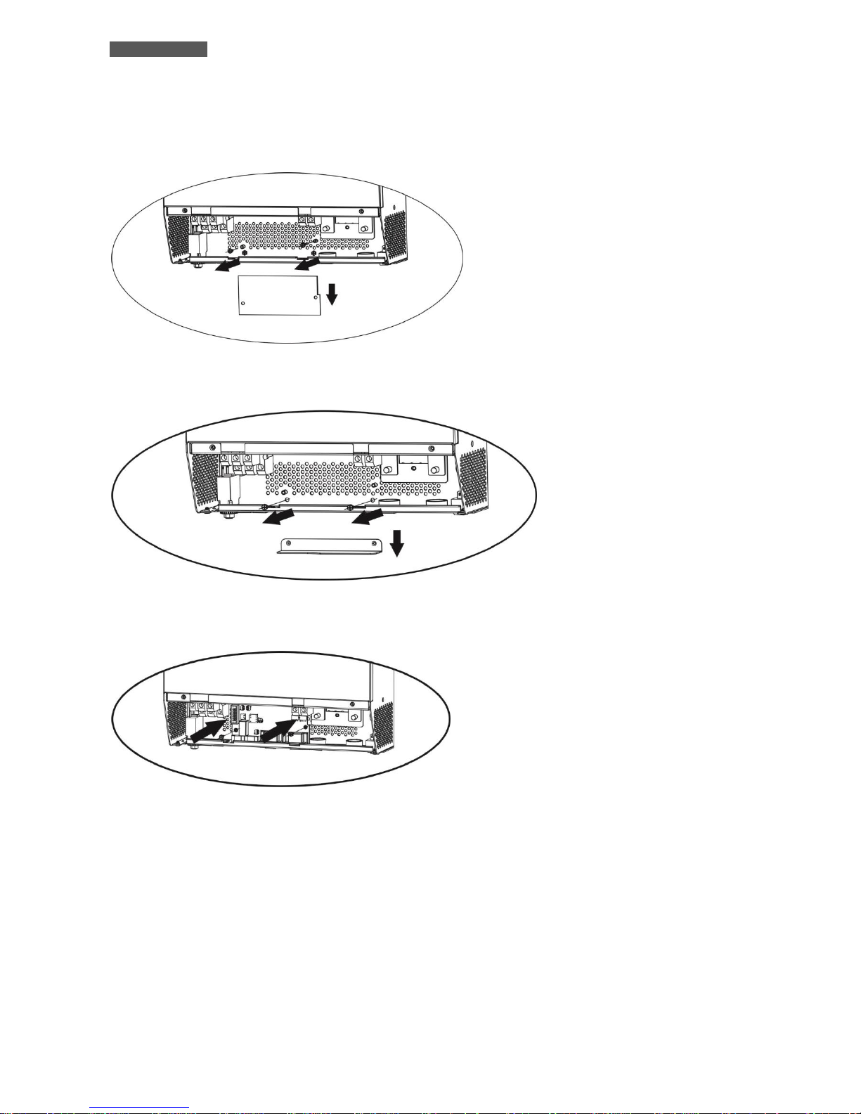
3. Remove the screws, as shown below; then remove the 2-pin flat cable, remove the 14-pin flat cable and remove the
electronic board placed under the communication board.
4. Remove the metal cover, as shown below.
5. Install the Parallel Board.
Page 31
ENGLISH
ATA Energy Storage System MM 25 User’s manual
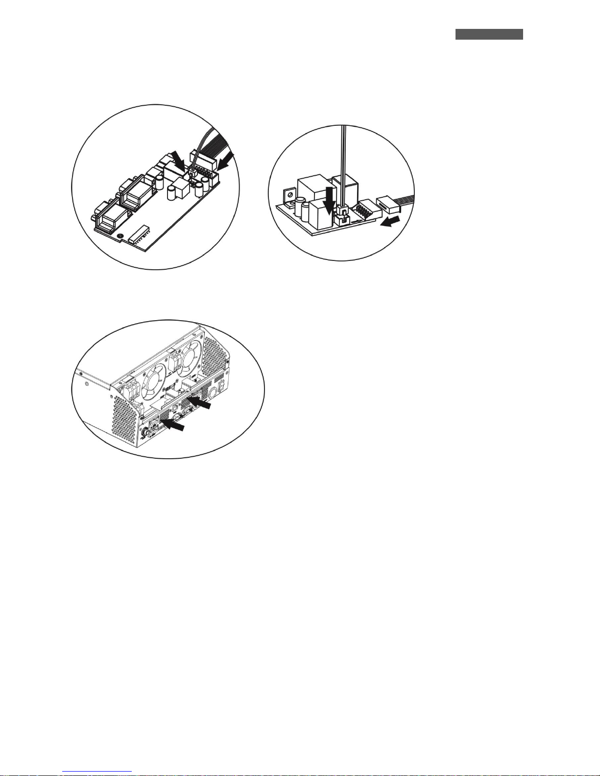
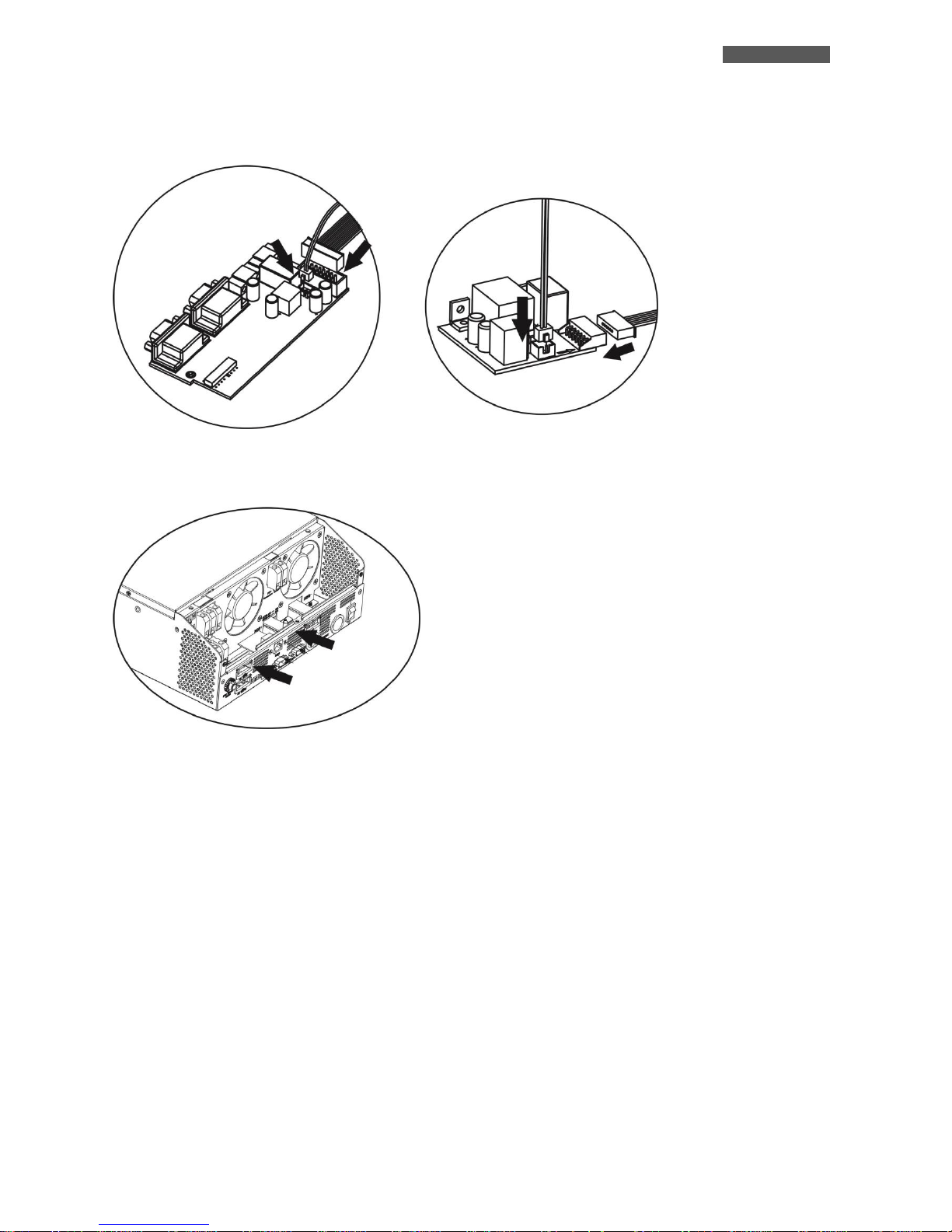
6. Reconnect the 2-pin and 14-pin flat cables to the Parallel board and Communication board, as shown below.
7. Install again the Communication board where it had been previously removed.
8. Reassemble the metal cover, removed at the point 1.
Scheda Parallelo
Scheda Comunicazioni
Page 32
ENGLISH
User’s manual 26 ATA Energy Storage System MM
11.4 Installation of ATA units
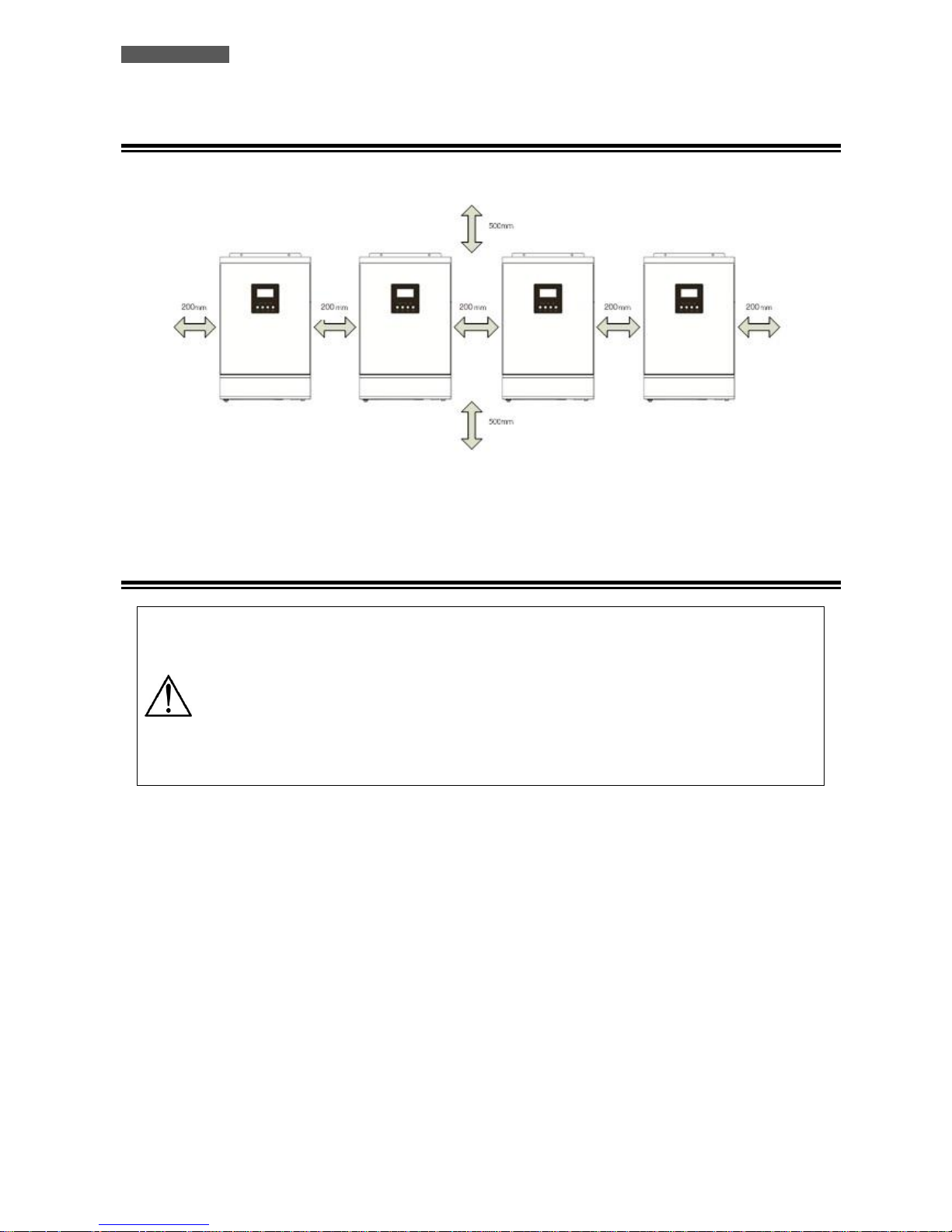
Refer to the figure below when installing the ATA units.
NOTE: for promoting aeration and increasing the dissipation of heat produced by each ATA, it is appropriate to install
the units leaving 20 cm of space between the units and 50 cm of space above and below of each unit. Be careful to
install the units at the same height.
11.5 Batteries Connection
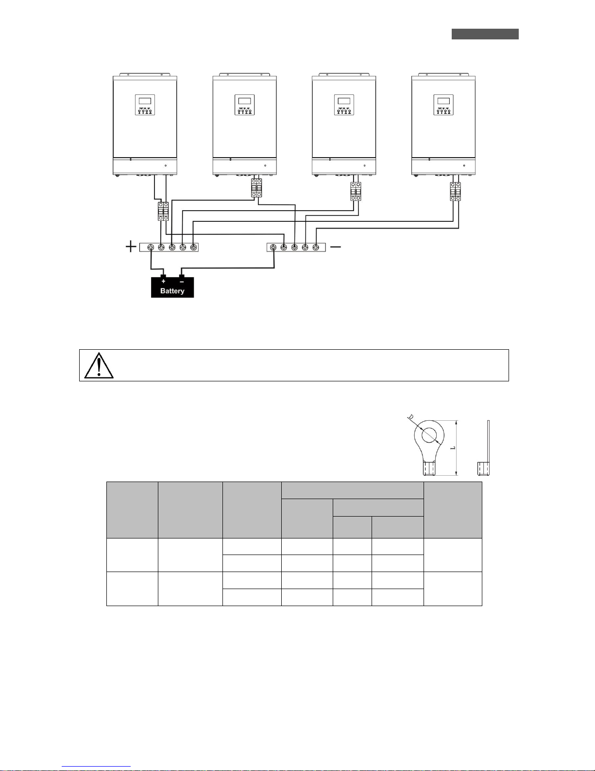
ATTENTION: the type of batteries set to each ATA must be identical, otherwise the system
reports error.
ATTENTION: the length of the connecting cables from batteries to ATA drives must be about the
same; otherwise the voltage difference, that could be between each ATA units and the batteries,
may cause a malfunction of the system.
ATTENTION: for safety we recommend to install a protection device (fuse) between each ATA
units and the batteries
Refer to the figure below when connecting the batteries.
Page 33
ENGLISH
ATA Energy Storage System MM 27 User’s manual
The battery pack can be also realized with batteries connected in parallel.
ATTENTION! The battery pack must be common to all inverters in parallel.
The following table shows the recommended size for wires and battery terminals.
Recommended size for wires and battery terminals:
ATA
MODEL
AMPERES
(typical)
WIRE
SIZE
RING TERMINAL
TIGHTENING
TORQUE
WIRE
SECTION
(mm2)
DIMENSIONS
D (mm)
L (mm)
4.0
67 A
1*4 AWG
22
6.4
33.2
2 ~ 3 Nm
2*8 AWG
14
6.4
29.2
5.0
84 A
1*4 AWG
22
6.4
33.2
2 ~ 3 Nm
2*8 AWG
14
6.4
29.2
Terminal:
Page 34
ENGLISH
User’s manual 28 ATA Energy Storage System MM
11.6 AC Utility Line Connection
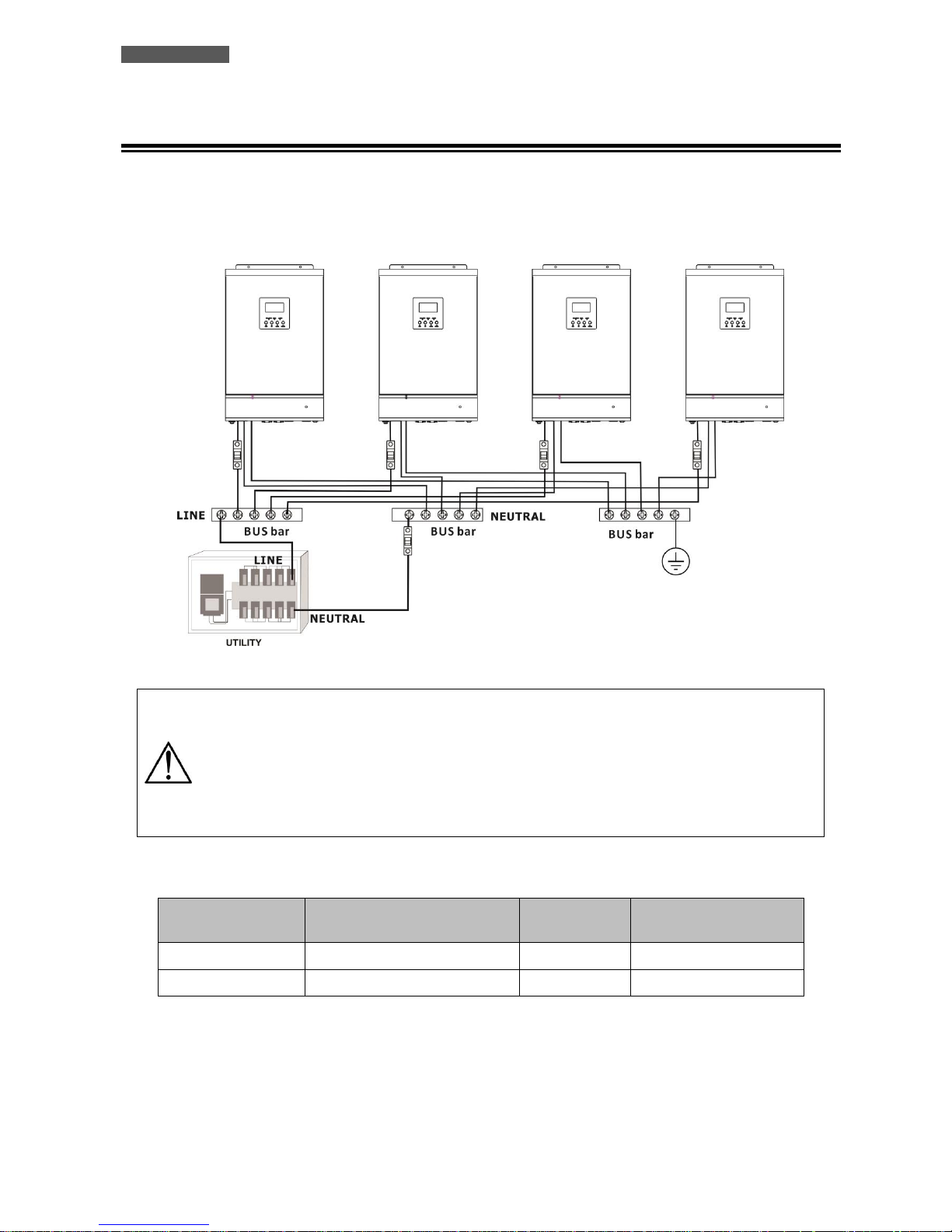
Connect the AC Utility Line to the power bars of the ATA units, and be sure to divide correctly LINE, NEUTRAL and
EARTH connections. For safety we recommend to install a protection device (fuse) on the Input LINE connection of
each ATA units and a protection device (fuse) on the NEUTRAL connection of the system. Refer to the diagram below.
ATTENTION: only the input LINE connection of each ATA are to be placed under a protection
system. You can not install the security systems on the input NEUTRAL connection of each ATA.
The input NEUTRAL connections are placed in common on the NEUTRAL bar. The protection of
the input NEUTRAL line must be placed between the power supply and the NEUTRAL bar.
ATTENTION: be sure that the length of all the power cables is as similar as possible for each
ATA, so as to ensure a right distribution of the absorbed current.
The following table shows the recommended size for wires.
ATA MODEL
MAX CURRENT PROTECTION
(fuse)
WIRE SIZE
TIGHTENING TORQUE
4.0
40 A
10 AWG
1.4 ~1.6Nm
5.0
50 A
8 AWG
1.4 ~1.6Nm
Page 35
ENGLISH
ATA Energy Storage System MM 29 User’s manual
11.7 Output Lines and Load Connection
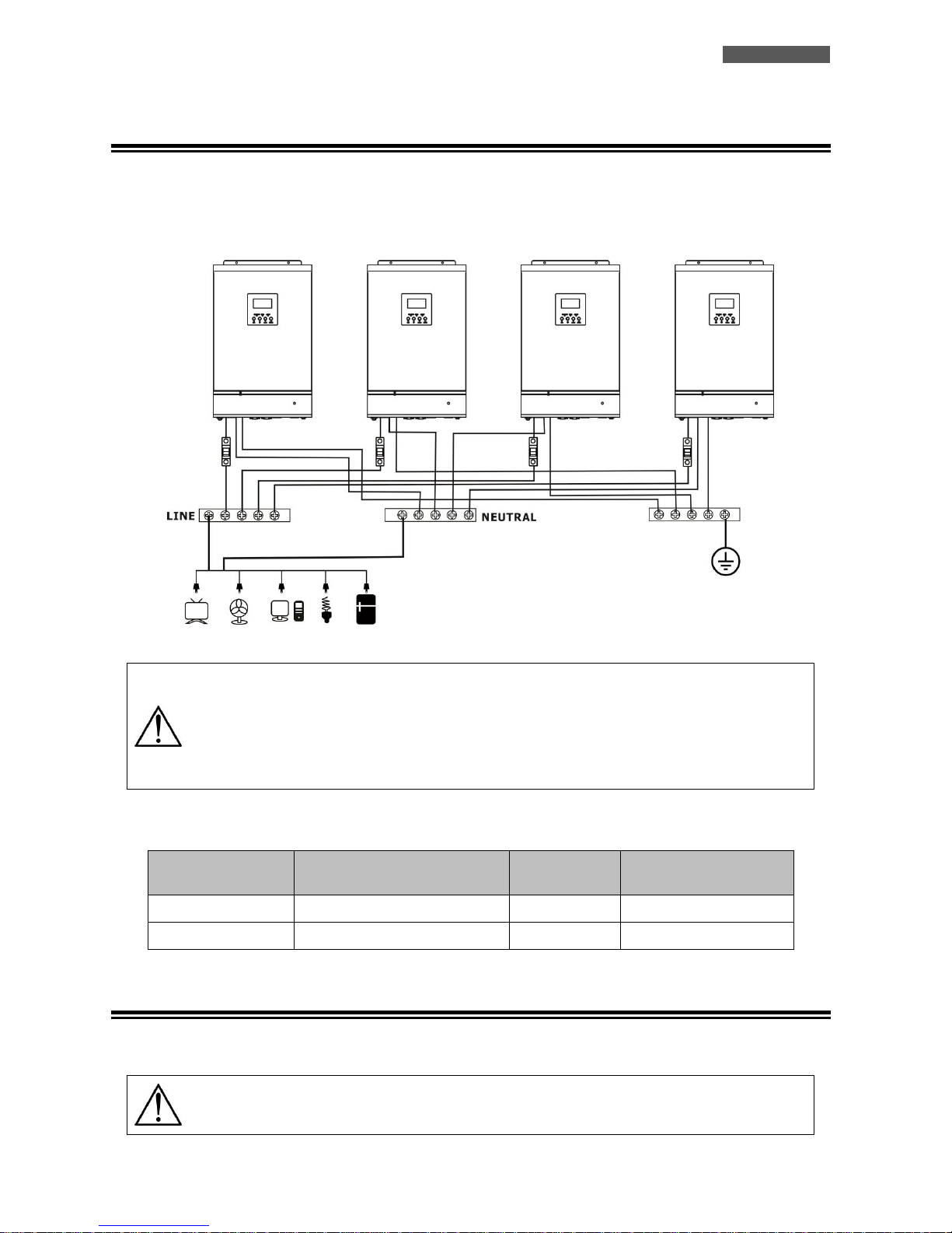
Connect the Output Line (LINE, NEUTRAL and EARTH) of each ATA unit to the respective connection bar. For safety we
recommend to install a protection device (fuse) on the Output LINE connection of each ATA unit. Refer to the diagram
below.
ATTENTION: only the Output LINE connection of each ATA are to be placed under a protection
system. You can not install the security systems on the Output NEUTRAL connection of each ATA.
The Output NEUTRAL lines are placed in common on the NEUTRAL connecting bar.
ATTENTION: be sure that the length of all the power cables is as similar as possible for each
ATA, so as to ensure a right distribution of the absorbed current.
The following table shows the recommended size for wires.
ATA MODEL
MAX CURRENT PROTECTION
(fuse)
WIRE SIZE
TIGHTENING TORQUE
4.0
40 A
10 AWG
1.4 ~ 1.6Nm
5.0
50 A
8 AWG
1.4 ~1.6Nm
11.8 PhotoVoltaic (PV) Panel Connection
Refer to the "Installation" section for the connections of the system of PV panels.
ATTENTION: each ATA unit must be connected to its own system of panels of PV panels. You can
not use only one system of PV panels in common for all ATA units.
Page 36
ENGLISH
User’s manual 30 ATA Energy Storage System MM
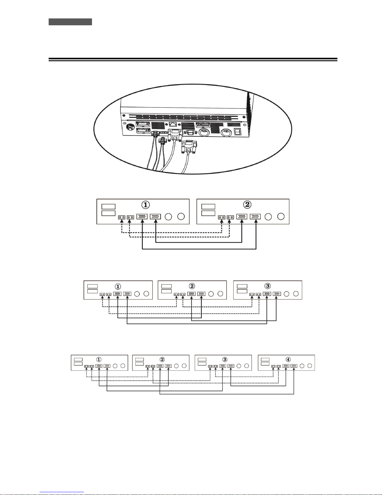
11.9 Connections of Parallel Kit cables
Refer to the figure below to connect the cables included in the kit parallel.
2 ATA units in parallel mode:
3 ATA units in parallel mode:
4 ATA units in parallel mode:
Page 37
ENGLISH
ATA Energy Storage System MM 31 User’s manual
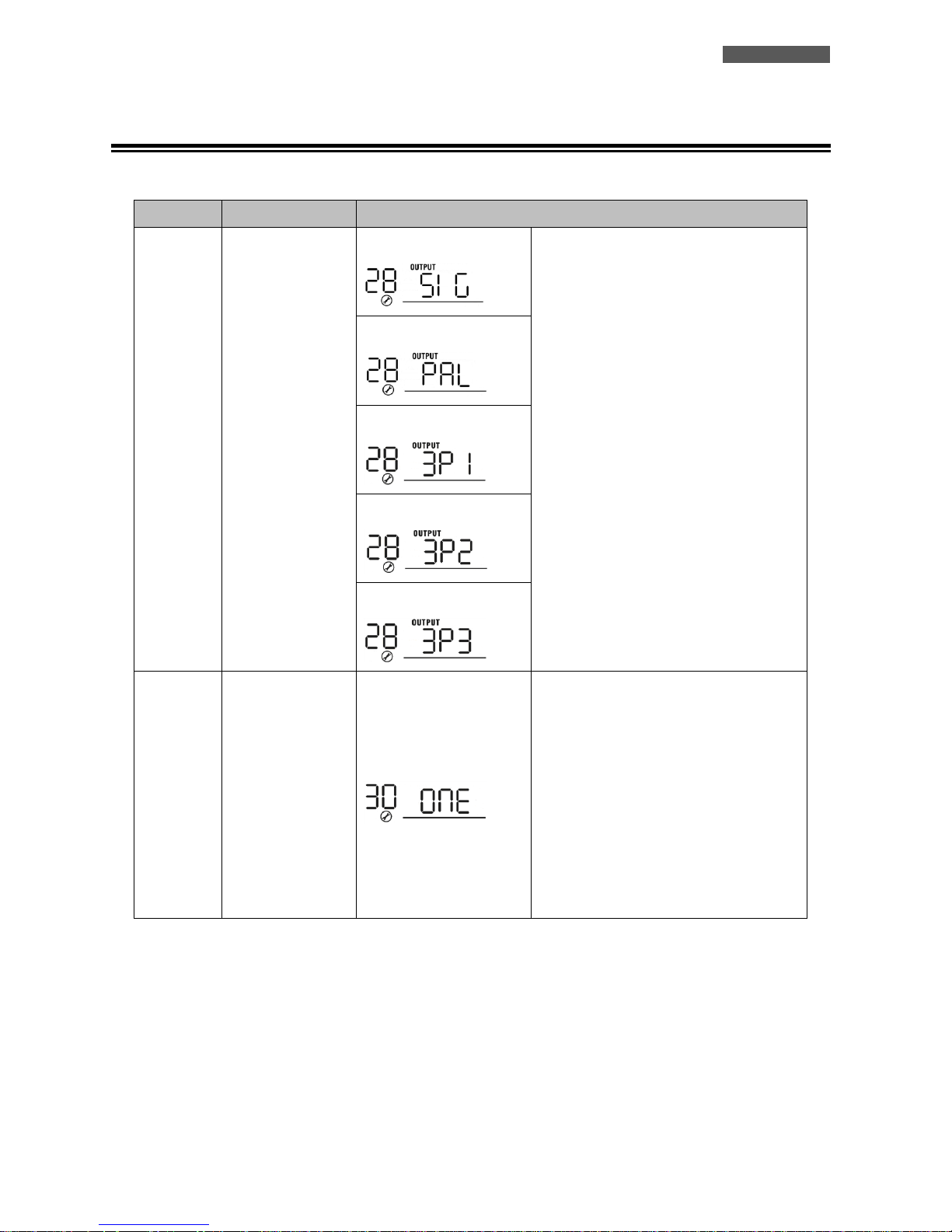
11.10 Setting Parameter
This parameter can only be set if the ATA unit is in stand-by mode.
NUMBER
DESCRIPTION
SELECTABLE OPTIONS
28
Output mode:
ATA can operate in:
Single mode,
Parallel mode,
Phase S mode,
Phase R mode,
Phase T mode.
Single Mode:
When the units are used in parallel with
single phase, please select “PAL” in
program 28.
It is required to have at least 3 inverters or
maximum 4 inverters to support threephase equipment. It’s required to have at
least one inverter in each phase or it’s up
to four inverters in one phase. Please
refers to 5-2 for detailed information.
Please select “3P1” in program 28 for the
inverters connected to L1 phase, “3P2” in
program 28 for the inverters connected to
L2 phase and “3P3” in program 28 for the
inverters connected to L3 phase.
Be sure to connect share current cable to
units which are on the same phase.
Do NOT connect share current cable
between units on different phases.
Besides, power saving function will be
automatically disabled.
Parallel Mode:
Phase S (L1):
Phase R (L2):
Phase T (L3):
30
PV judge condition
(Only apply for
setting “Solar first”
in program 1:
Output source
priority)
One Inverter (Default):
When “ONE” is selected, as long as one of
inverters has been connected to PV
modules and PV input is normal, parallel or
3-phase system will continue working
according to rule of “solar first” setting.
For example, two units are connected in
parallel and set “SOL” in output source
priority. If one of two units has connected
to PV modules and PV input is normal, the
parallel system will provide power to loads
from solar or battery power. If both of
them are not sufficient, the system will
provide power to loads from utility.
Page 38
ENGLISH
User’s manual 32 ATA Energy Storage System MM
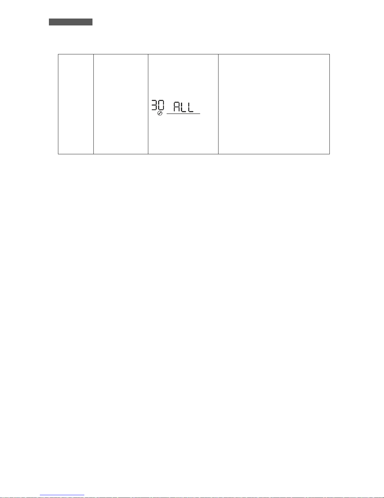
All of Inverters:
When “ALL” is selected, parallel or 3-phase
system will continue working according to
rule of “solar first” setting only when all of
inverters are connected to PV modules.
For example, two units are connected in
parallel and set “SOL” in output source
priority. When selecting “ALL” in program
30, it’s necessary to have all inverters
connected to PV modules and PV input is
normal to allow the system to provide
power to loads from solar and battery
power. Otherwise, the system will provide
power to loads from utility.
Page 39
ENGLISH
ATA Energy Storage System MM 33 User’s manual
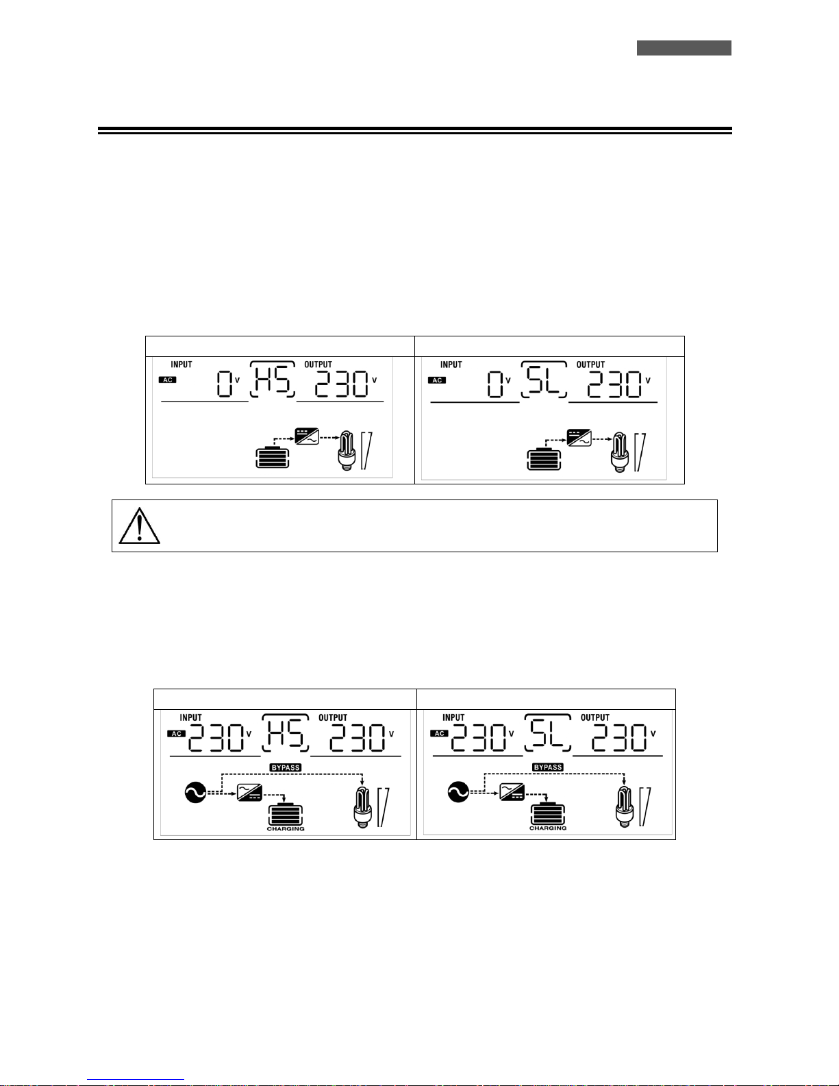
11.11 Startup
1. Before the Startup of the system:
Check all the connections of the Parallel system.
Be sure that the protection systems on the Input LINE connections are open and Input NEUTRAL connections are
connected in common.
2. Place the circuit breaker of batteries in “ON” position.
3. Place the On/Off switch of each ATA unit in “ON” position.
LCD Display – Master ATA
LCD Display – Slave ATA
ATTENTION: the Master and Slave units are randomly selected.
4. Place the circuit breakers of PV panels in “ON” position.
5. Turn ON all the protections of Input Line. We recommended to connect all inverter to the AC Utility Line at the
same time, otherwise the error nr. 82 will be displayed. Anyway the ATA units will restart automatically; so when they
detect the AC Utility Line begin to work normally.
LCD Display – Master ATA
LCD Display – Slave ATA
6. If no other errors are displayed, the startup procedure of the parallel system is completed.
7. Finally turn ON the switches of the devices to be powered. The system will power these devices.
Page 40
ENGLISH
User’s manual 34 ATA Energy Storage System MM
ATTENTION: to prevent an overload condition occurs, we recommended to have the system up
and running before you activate the devices to be supplied.
ATTENZIONE: in this type of operation there are intervention times, then this may lead to
interruptions of operation to those devices that are not capable of withstanding the presence of
an intervention time.
11.12 Faults and Alarms
CODE
DESCRIPTION
ACTION TO SOLVE
60
Error in the current control system.
1. Restart the System.
2. If the problem persists, contact the Customer
Service.
71
The firmware installed on each ATA
unit are not equal.
1. Updating the inverter with the same firmware.
2. If the problem persists, contact the Customer
Service
72
The output current for each
inverter is different.
1. Be sure that the sharing cables are properly
connected and restart the System.
2. If the problem persists, contact the Customer
Service.
80
Data communication loss.
1. Be sure that the communication cables are
properly connected and restart the System.
2. If the problem persists, contact the Customer
Service.
81
Host data loss.
82
Synchronization loss.
83
The battery voltage detected on
each ATA is different.
1. Be sure all the ATA units are properly
connected to the same battery pack.
2. If the problem persists, contact the Customer
Service
84
The input voltage and frequency
measured on each ATA drives are
different.
1. Check all the Input connections and restart the
System.
2. If the problem persists, contact the Customer
Service
85
Unbalanced output current.
1. Restart the System.
2. If the problem persists, contact the Customer
Service
86
The Setting Parameter is not the
same in all units.
1. Turn all the ATA units in stand-by mode and
check the Setting Parameter (nr. 28) on each
unit.
2. If the problem persists, contact the Customer
Service
Page 41
ENGLISH
ATA Energy Storage System MM 35 User’s manual
12 Three Phases Connection
12.1 Introduction
It is necessary to connect 3 pcs of identical power and specification ATA in parallel, installing an ATA for each phase:
so the max handling power is 15KVA/12KW (for ATA 5.0 MM).
12.2 Parallel Kit
The parallel kit consists of:
12.3 Parallel Kit Installation
1. Remove the metal cover, see the following figure.
2. Remove the Communication Board (with RJ45 and USB port).
Parallel Board
Parallel Cable
Sharing Current Cable
Page 42
ENGLISH
User’s manual 36 ATA Energy Storage System MM
3. Remove the screws, as shown below; then remove the 2-pin flat cable, remove the 14-pin flat cable and remove the
electronic board placed under the communication board.
4. Remove the metal cover, as shown below.
5. Install the Parallel Board.
Page 43
ENGLISH
ATA Energy Storage System MM 37 User’s manual
6. Reconnect the 2-pin and 14-pin flat cables to the Parallel board and Communication board, as shown below.
7. Install again the Communication board where it had been previously removed.
8. Reassemble the metal cover, removed at the point 1.
Scheda Parallelo
Scheda Comunicazioni
Page 44
ENGLISH
User’s manual 38 ATA Energy Storage System MM
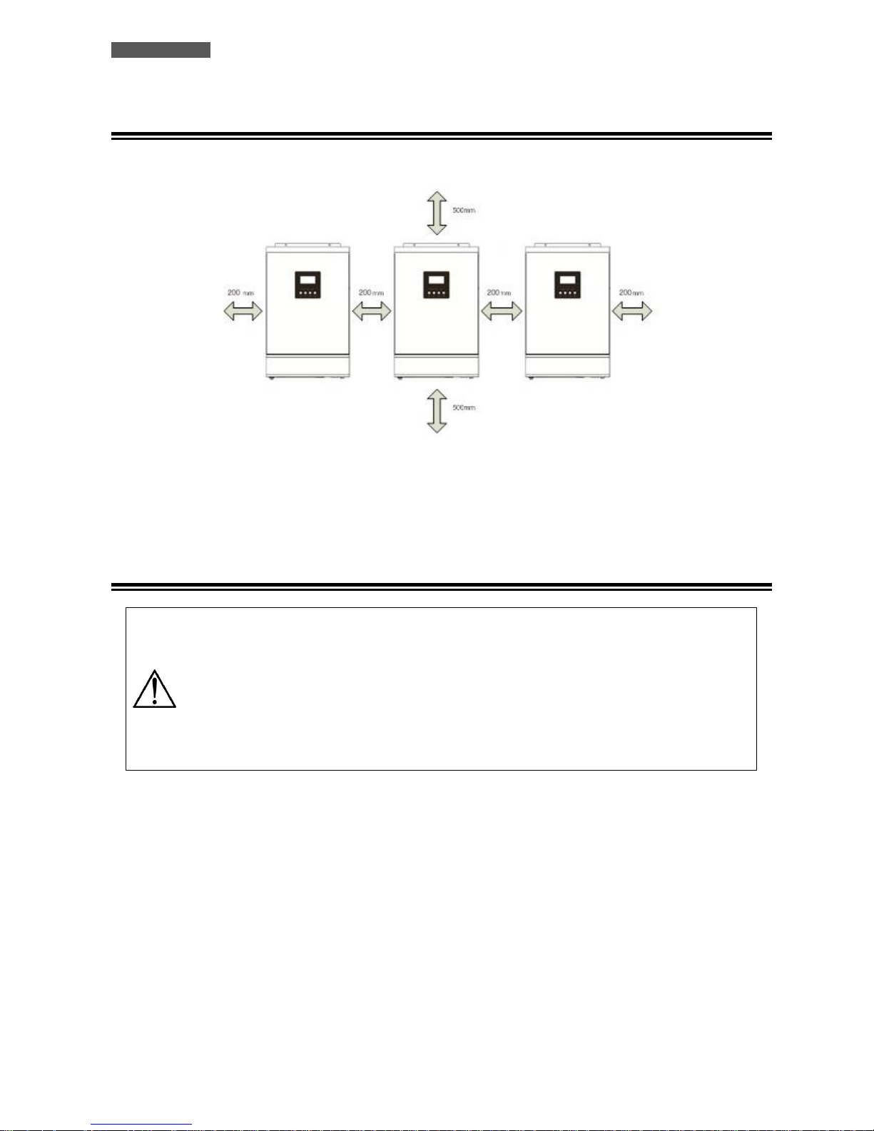
12.4 Installation of ATA units
Refer to the figure below when installing the ATA units.
NOTE: for promoting aeration and increasing the dissipation of heat produced by each ATA, it is appropriate to install
the units leaving 20 cm of space between the units and 50 cm of space above and below of each unit. Be careful to
install the units at the same height.
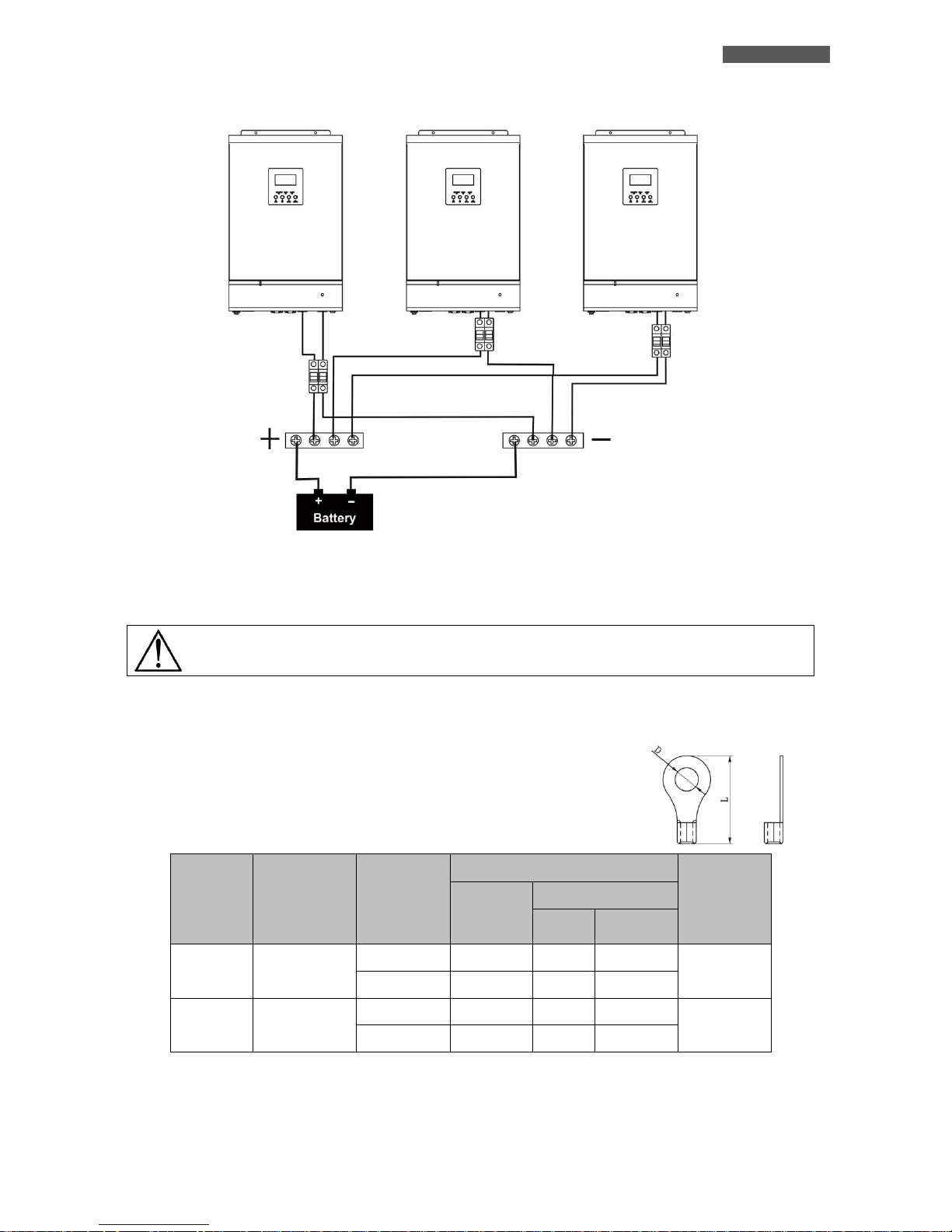
12.5 Batteries Connection
ATTENTION: the type of batteries set to each ATA must be identical, otherwise the system
reports error.
ATTENTION: the length of the connecting cables from batteries to ATA drives must be about the
same; otherwise the voltage difference, that could be between each ATA units and the batteries,
may cause a malfunction of the system.
ATTENTION: for safety we recommend to install a protection device (fuse) between each ATA
units and the batteries
Refer to the figure below when connecting the batteries.
Page 45
ENGLISH
ATA Energy Storage System MM 39 User’s manual
The battery pack can be also realized with batteries connected in parallel.
ATTENTION! The battery pack must be common to all inverters in parallel.
The following table shows the recommended size for wires and battery terminals.
Recommended size for wires and battery terminals:
ATA
MODEL
AMPERES
(typical)
WIRE
SIZE
RING TERMINAL
TIGHTENING
TORQUE
WIRE
SECTION
(mm2)
DIMENSIONS
D (mm)
L (mm)
4.0
67 A
1*4 AWG
22
6.4
33.2
2 ~ 3 Nm
2*8 AWG
14
6.4
29.2
5.0
84 A
1*4 AWG
22
6.4
33.2
2 ~ 3 Nm
2*8 AWG
14
6.4
29.2
Terminal:
Page 46
ENGLISH
User’s manual 40 ATA Energy Storage System MM
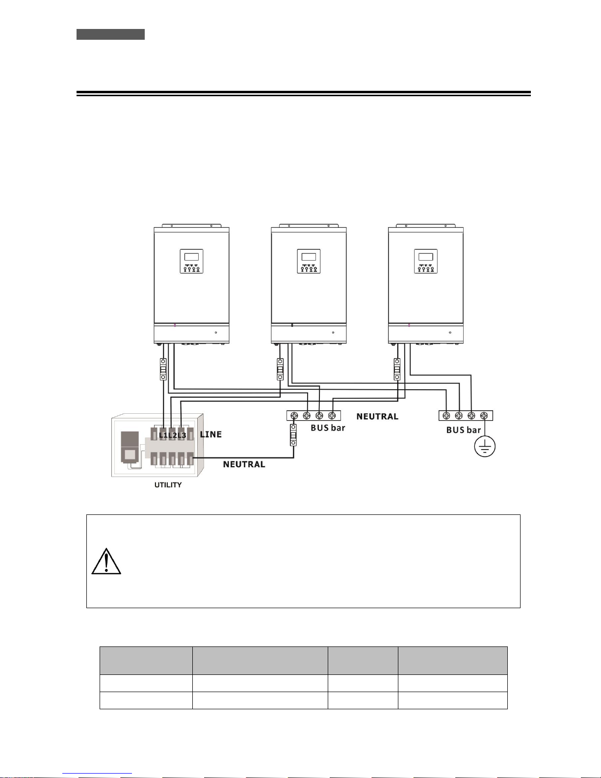
12.6 AC Utility Line Connection
Connect the Input LINE phase of the first ATA to the phase L1 of AC Three Phases Utility; connect the Input LINE
phase of the second ATA to the phase L2; then connect the Input LINE phase of the third ATA to the phase L3.
Connect the Input NEUTRAL phase of each ATA units and the NEUTRAL of AC Three Phases Utility to the NEUTRAL
power bar. Connect the EARTH of each ATA unit to the EARTH bar. For safety we recommend to install a protection
device (fuse) on the Input LINE connection of each ATA units and a protection device (fuse) on the NEUTRAL
connection of the system. Refer to the diagram below.
ATTENTION: only the input LINE connection of each ATA are to be placed under a protection
system. You can not install the security systems on the input NEUTRAL connection of each ATA.
The input NEUTRAL connections are placed in common on the NEUTRAL bar. The protection of
the input NEUTRAL line must be placed between the power supply and the NEUTRAL bar.
ATTENTION: be sure that the length of all the power cables is as similar as possible for each
ATA, so as to ensure a right distribution of the absorbed current.
The following table shows the recommended size for wires.
ATA MODEL
MAX CURRENT PROTECTION
(fuse)
WIRE SIZE
TIGHTENING TORQUE
4.0
40 A
10 AWG
1.4 ~1.6Nm
5.0
50 A
8 AWG
1.4 ~1.6Nm
Page 47
ENGLISH
ATA Energy Storage System MM 41 User’s manual
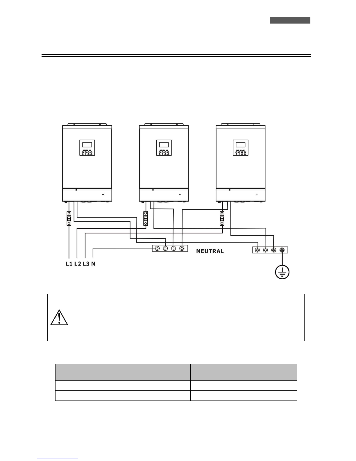
12.7 Output Lines and Load Connection
Connect the Output LINE phase of each ATA unit to the respective Output Phase (L1, L2, L3) of the Three Phases
Output Line.
Connect the Output NEUTRAL phase of each ATA and the NEUTRAL of AC Three Phases Output the NEUTRAL power bar.
Connect the EARTH of each ATA unit to the EARTH bar. For safety we recommend to install a protection device (fuse)
on the Output LINE phase of each ATA unit. Refer to the diagram below.
ATTENTION: only the Output LINE connection of each ATA are to be placed under a protection
system. You can not install the security systems on the Output NEUTRAL connection of each ATA.
The Output NEUTRAL lines are placed in common on the NEUTRAL connecting bar.
ATTENTION: be sure that the length of all the power cables is as similar as possible for each
ATA, so as to ensure a right distribution of the absorbed current.
The following table shows the recommended size for wires.
ATA MODEL
MAX CURRENT PROTECTION
(fuse)
WIRE SIZE
TIGHTENING TORQUE
4.0
40 A
10 AWG
1.4 ~ 1.6Nm
5.0
50 A
8 AWG
1.4 ~1.6Nm
Page 48
ENGLISH
User’s manual 42 ATA Energy Storage System MM
12.8 PhotoVoltaic (PV) Panel Connection
Refer to the "Installation" section for the connections of the system of PV panels.
ATTENTION: each ATA unit must be connected to its own system of panels of PV panels. You can
not use only one system of PV panels in common for all ATA units.
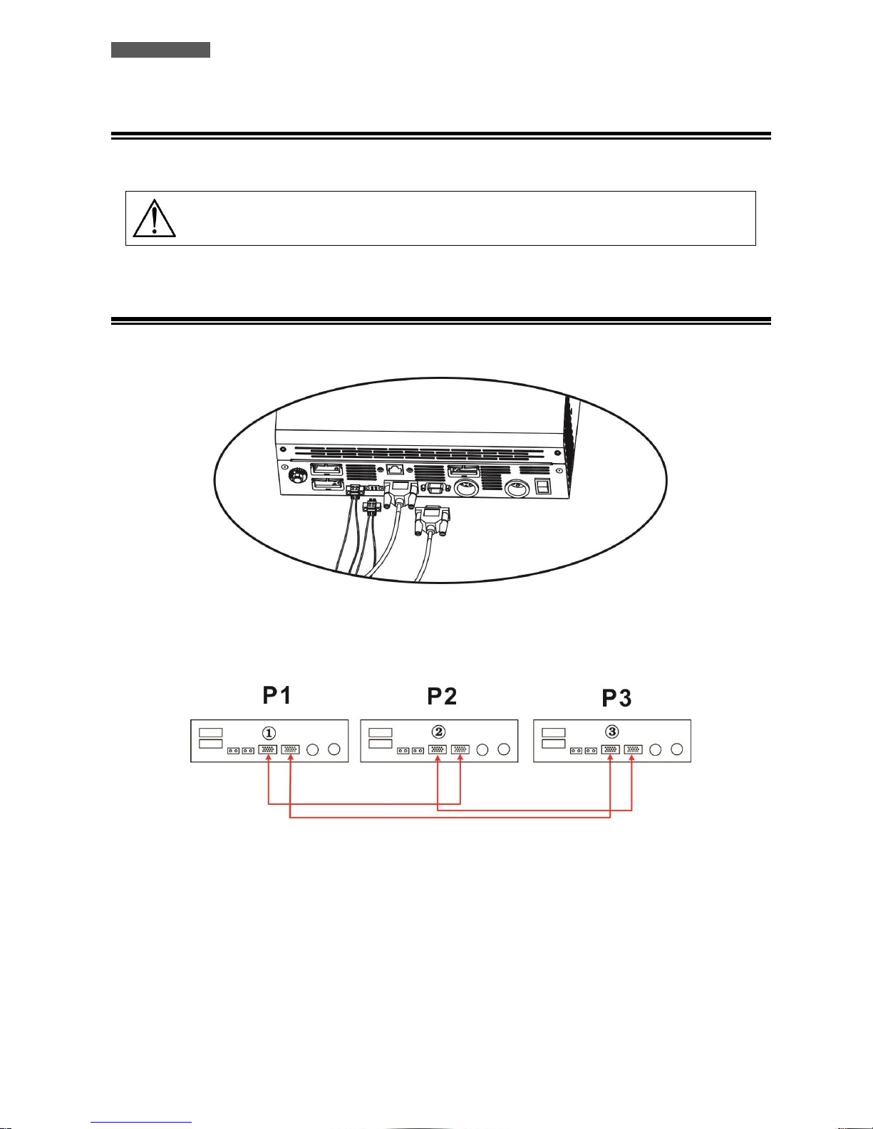
12.9 Connections of Parallel Kit cables
Refer to the figure below to connect the cables included in the kit parallel.
Below the connection between the ATA units in a Three-Phase System.
WARNING: Do not connect the current sharing cable between the inverters which are in
different phases. Otherwise, it may damage the inverters. Connect only the cables like indicate
in figure.
Page 49
ENGLISH
ATA Energy Storage System MM 43 User’s manual
12.10 Setting Parameter
This parameter can only be set if the ATA unit is in stand-by mode.
NUMBER
DESCRIPTION
SELECTABLE OPTIONS
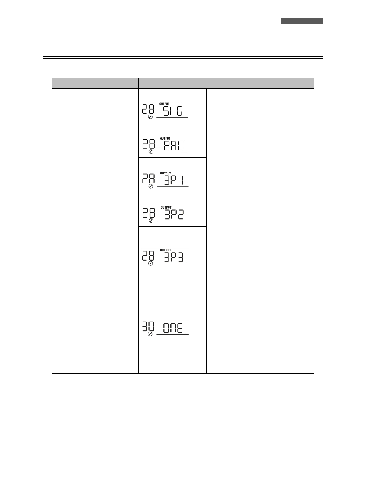
28
Output mode:
ATA can operate in:
Single mode,
Parallel mode,
Phase S mode,
Phase R mode,
Phase T mode.
Single Mode:
When the units are used in parallel with
single phase, please select “PAL” in
program 28.
It is required to have at least 3 inverters or
maximum 6 inverters to support threephase equipment. It’s required to have at
least one inverter in each phase or it’s up
to four inverters in one phase. Please
refers to 5-2 for detailed information.
Please select “3P1” in program 28 for the
inverters connected to L1 phase, “3P2” in
program 28 for the inverters connected to
L2 phase and “3P3” in program 28 for the
inverters connected to L3 phase.
Be sure to connect share current cable to
units which are on the same phase.
Do NOT connect share current cable
between units on different phases.
Besides, power saving function will be
automatically disabled.
Parallel Mode:
Phase S (L1):
Phase R (L2):
Phase T (L3):
30
PV judge condition
(Only apply for
setting “Solar first”
in program 1:
Output source
priority)
One Inverter (Default):
When “ONE” is selected, as long as one of
inverters has been connected to PV
modules and PV input is normal, parallel or
3-phase system will continue working
according to rule of “solar first” setting.
For example, two units are connected in
parallel and set “SOL” in output source
priority. If one of two units has connected
to PV modules and PV input is normal, the
parallel system will provide power to loads
from solar or battery power. If both of
them are not sufficient, the system will
provide power to loads from utility.
Page 50
ENGLISH
User’s manual 44 ATA Energy Storage System MM
All of Inverters:
When “ALL” is selected, parallel or 3-phase
system will continue working according to
rule of “solar first” setting only when all of
inverters are connected to PV modules.
For example, two units are connected in
parallel and set “SOL” in output source
priority. When selecting “ALL” in program
30, it’s necessary to have all inverters
connected to PV modules and PV input is
normal to allow the system to provide
power to loads from solar and battery
power. Otherwise, the system will provide
power to loads from utility.
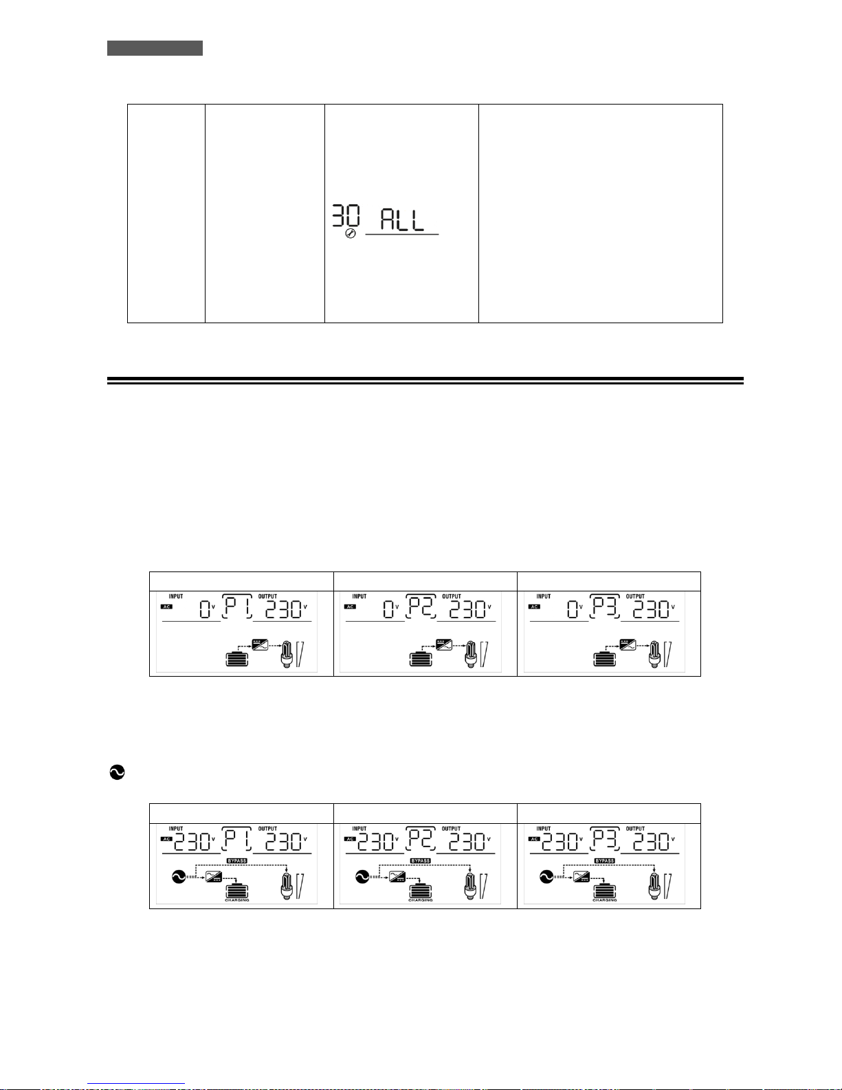
12.11 Startup
1. Before the Startup of the system:
Check all the connections of the Parallel system.
Be sure that the protection systems on the Input LINE connections are open and Input NEUTRAL connections are
connected in common.
2. Place the circuit breaker of batteries in “ON” position.
3. Place the On/Off switch of the 3 ATA units in “ON” position.
LCD Display – ATA L1 phase
LCD Display – ATA L2 phase
LCD Display – ATA L3 phase
4. Place the circuit breakers of PV panels in “ON” position.
5. Turn ON all the protections of Input Line. If the AC Three Phase Utility Line is present and ATA units are set
correctly in relation to the phase on which they are placed, the ATA units will operate properly. Otherwise, the icon
will flash and the ATA will not work.
LCD Display – ATA L1 phase
LCD Display – ATA L2 phase
LCD Display – ATA L3 phase
6. If no other errors are displayed, the startup procedure of the parallel system is completed.
7. Finally turn ON the switches of the devices to be powered. The system will power these devices.
Page 51
ENGLISH
ATA Energy Storage System MM 45 User’s manual
ATTENTION: to prevent an overload condition occurs, we recommended to have the system up
and running before you activate the devices to be supplied.
ATTENZIONE: in this type of operation there are intervention times, then this may lead to
interruptions of operation to those devices that are not capable of withstanding the presence of
an intervention time.
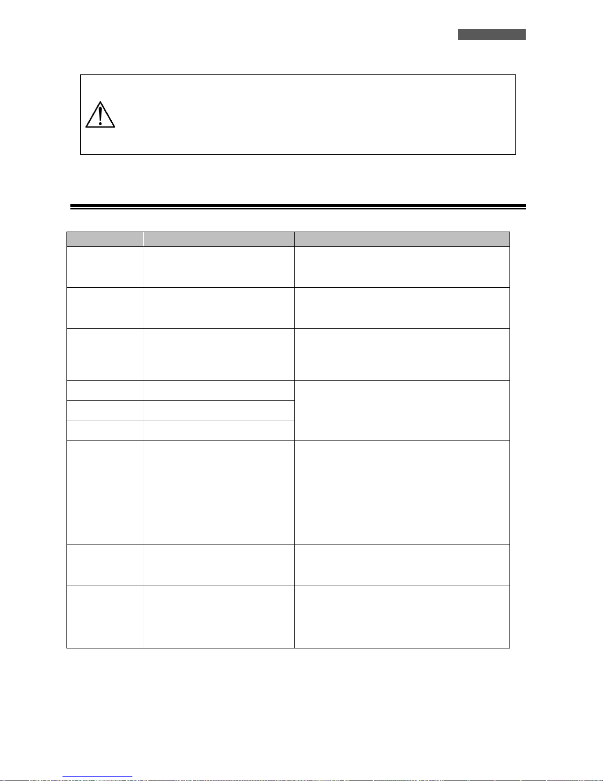
12.12 Faults and Alarm
CODE
DESCRIPTION
ACTION TO SOLVE
60
Error in the current control system.
3. Restart the System.
4. If the problem persists, contact the Customer
Service.
71
The firmware installed on each ATA
unit are not equal.
1. Updating the inverter with the same firmware.
2. If the problem persists, contact the Customer
Service
72
The output current for each inverter
is different.
3. Be sure that the sharing cables are properly
connected and restart the System.
4. If the problem persists, contact the Customer
Service.
80
Data communication loss.
1. Be sure that the communication cables are
properly connected and restart the System.
2. If the problem persists, contact the Customer
Service.
81
Host data loss.
82
Synchronization loss.
83
The battery voltage detected on
each ATA is different.
3. Be sure all the ATA units are properly connected
to the same battery pack.
4. If the problem persists, contact the Customer
Service
84
The input voltage and frequency
measured on each ATA drives are
different.
3. Check all the Input connections and restart the
System.
4. If the problem persists, contact the Customer
Service
85
Unbalanced output current.
3. Restart the System.
4. If the problem persists, contact the Customer
Service
86
The Setting Parameter is not the
same in all units.
3. Turn all the ATA units in stand-by mode and
check the Setting Parameter (nr. 28) on each
unit.
4. If the problem persists, contact the Customer
Service
Page 52
ENGLISH
User’s manual 46 ATA Energy Storage System MM
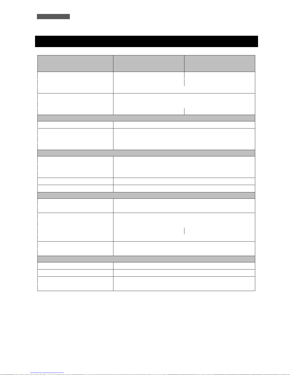
13 Technical Characteristics
Model ATA Energy Storage
System
4.0
5.0
Power
4000 VA
5000 VA
Nominal power
3200 W
4000 W
Dimensions (W x H x D)
29,5 x 54 x 14 cm
Cooling
Fan cooling
Audible noise
< 40 dBA a 1 m
Weight
12,5 kg
13,5 kg
INPUT MAINS
Number of phases
1F+N
Nominal Voltage
Single-phase 230 Vac
Input voltage range
170-280 Vac for personal computers / 90-280 Vac for home appliances (selectable)
Nominal frequency
50/60 Hz (automatic selection)
INPUT PHOTOVOLTAIC PANELS
Maximum PV array power
3750 Wp
MPPT range operating voltage
60-115 Vdc
Maximum PV array oper circuit power
145 Vdc
Maximum PV array input current
60 A
Maximum Efficiency
98%
OUTPUT
Number of phases
1F+N
Nominal Voltage
Single-phase 230 Vac
Nominal frequency
50/60 Hz (automatic selection)
Waveform
Sinewave
Surge Power
6400 W for 5s
8000 W for 5s
Efficiency
93%
Overload capability
10s 110%-150%/ 5s >150%
Transfer time
10 ms for personal computer - 20 ms for home appliances
BATTERY
Type
AGM/GEL
Battery voltage
48 Vdc (floating charger voltage 54 Vdc - over charger protection 60 Vdc)
Maximum charger current
120 A
Battery number
4 (12 Vdc)
Page 53
ENGLISH
ATA Energy Storage System MM 47 User’s manual
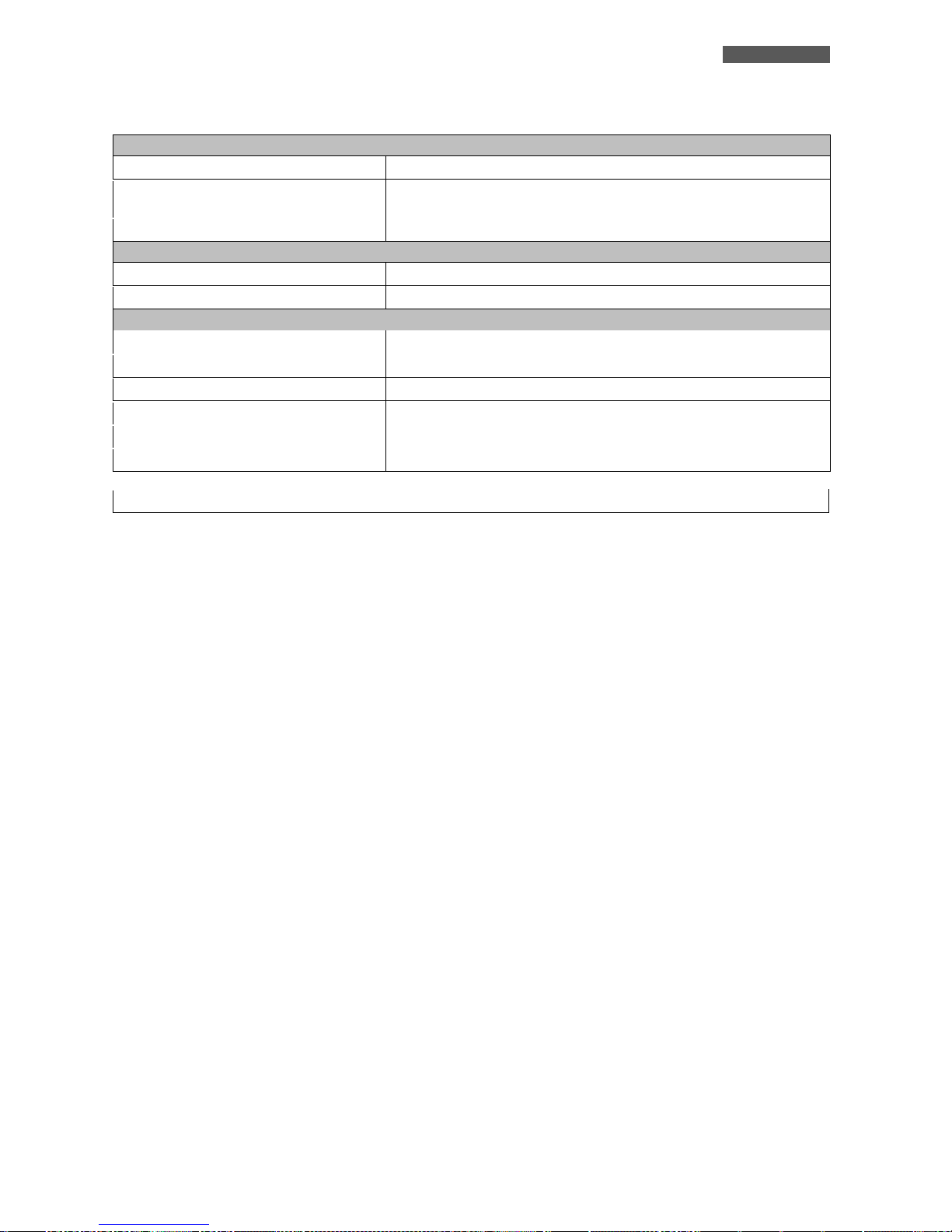
INTERFACING
Interface (communication port)
USB/RJ45 (RS232)
Software
WatchPower (compatible with WINDOWS, MAC OS X up to version 10.8, UNIX,
LINUX, ecc.)
External RS485 interface
Yes (optional)
PARALLEL CONFIGURATION
Parallel interface
Yes (optional)
Parallel unit
Up to 4 units
ENVIROMENTAL SPECIFICATION
Storage temperature
From -15 to 60 °C
Working temperature
From 0 to 55 °C
Humidity
5%-95% without condensation
Maximum altitude
3000 m
IP protection
IP20
Certifications
CE
Technical data may change without prior notice
Page 54
ENGLISH
User’s manual 48 ATA Energy Storage System MM
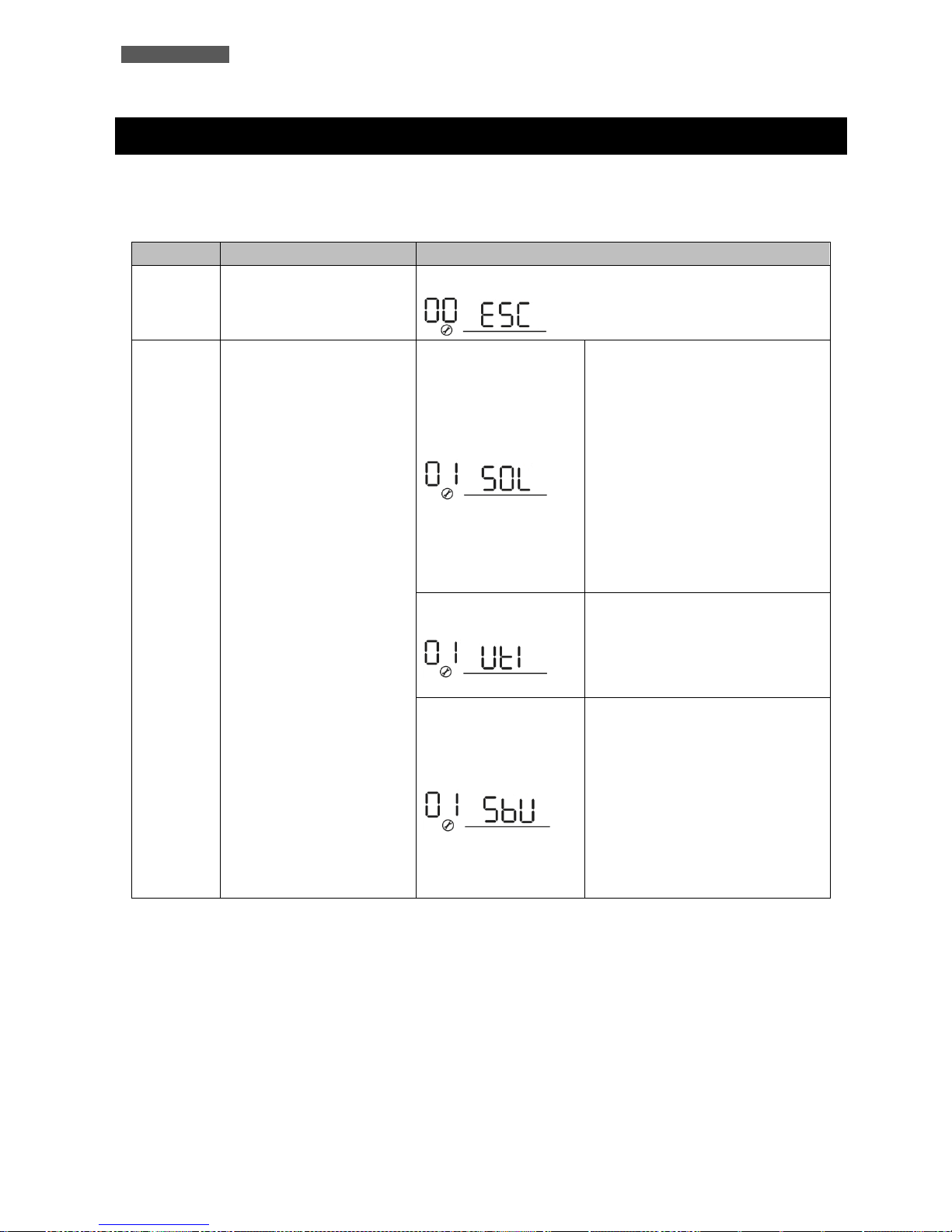
14 Settings
After pressing and holding “ENTER” button for 3 seconds, the unit will enter setting mode. Press “UP” or “DOWN”
button to select setting programs. And then, press “ENTER” button to confirm the selection or “ESC” button to exit.
SETTING
DESCRIPTION
SELECTABLE OPTIONS
00
Exit setting mode
Escape
01
Output source priority:
To configure load power
source priority
Solar first
Solar energy provides power to the
loads as first priority.
If solar energy is not sufficient to
power all connected loads, battery
energy will supply power the loads at
the same time.
Utility provides power to the loads
only when any one condition happens:
- Solar energy is not available
- Battery voltage drops to either lowlevel warning voltage or the setting
point in program 12.
Utility first
Utility will provide power to the loads
as first priority.
Solar and battery energy will provide
power to the loads only when utility
power is not available.
SBU priority (default)
Solar energy provides power to the
loads as first priority.
If solar energy is not sufficient to
power all connected loads, battery
energy will supply power to the loads
at the same time.
Utility provides power to the loads
only when battery voltage drops to
either low-level warning voltage or
the setting point in program 12.
Page 55
ENGLISH
ATA Energy Storage System MM 49 User’s manual
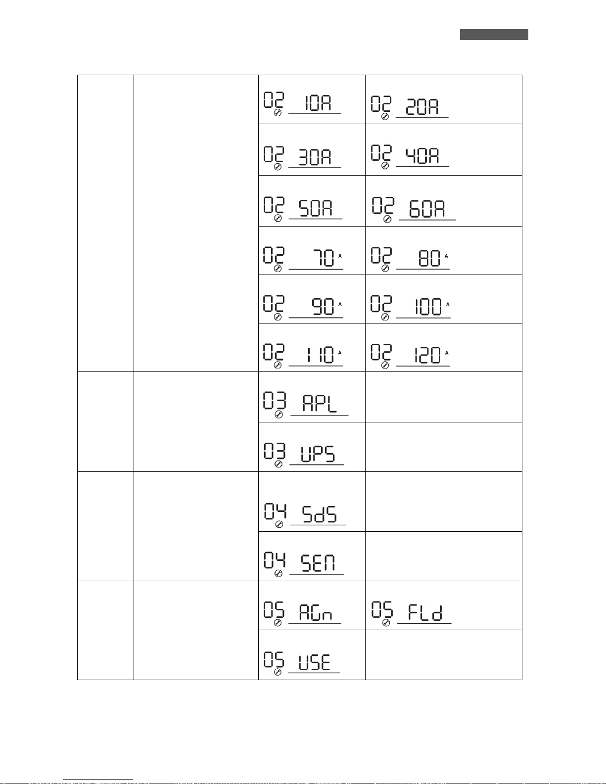
02
Maximum charging current:
To configure total charging
current for solar chargers.
(If selected “SNU” into
parameter 16 the max.
charging current = utility
charging current + solar
charging current)
10A
20A
30A
40A
50A
60A (default)
70A
80A
90A
100A
110A
120A
03
AC input voltage range
Appliances
If selected, acceptable AC input
voltage range will be within 90280VAC.
UPS (default)
If selected, acceptable AC input
voltage range will be within 170280VAC.
04
Power saving mode
enable/disable
Saving mode disable
(default)
If disabled, no matter connected load
is low or high, the on/off status of
inverter output will not be effected.
Saving mode enable
If enabled, the output of inverter will
be off when connected load is pretty
low or not detected.
05
Battery type
AGM (default)
Flooded
User-Defined
If “User-Defined” is selected, battery
charge voltage and low DC cut-off
voltage can be set up in program 26,
27 and 29.
Page 56
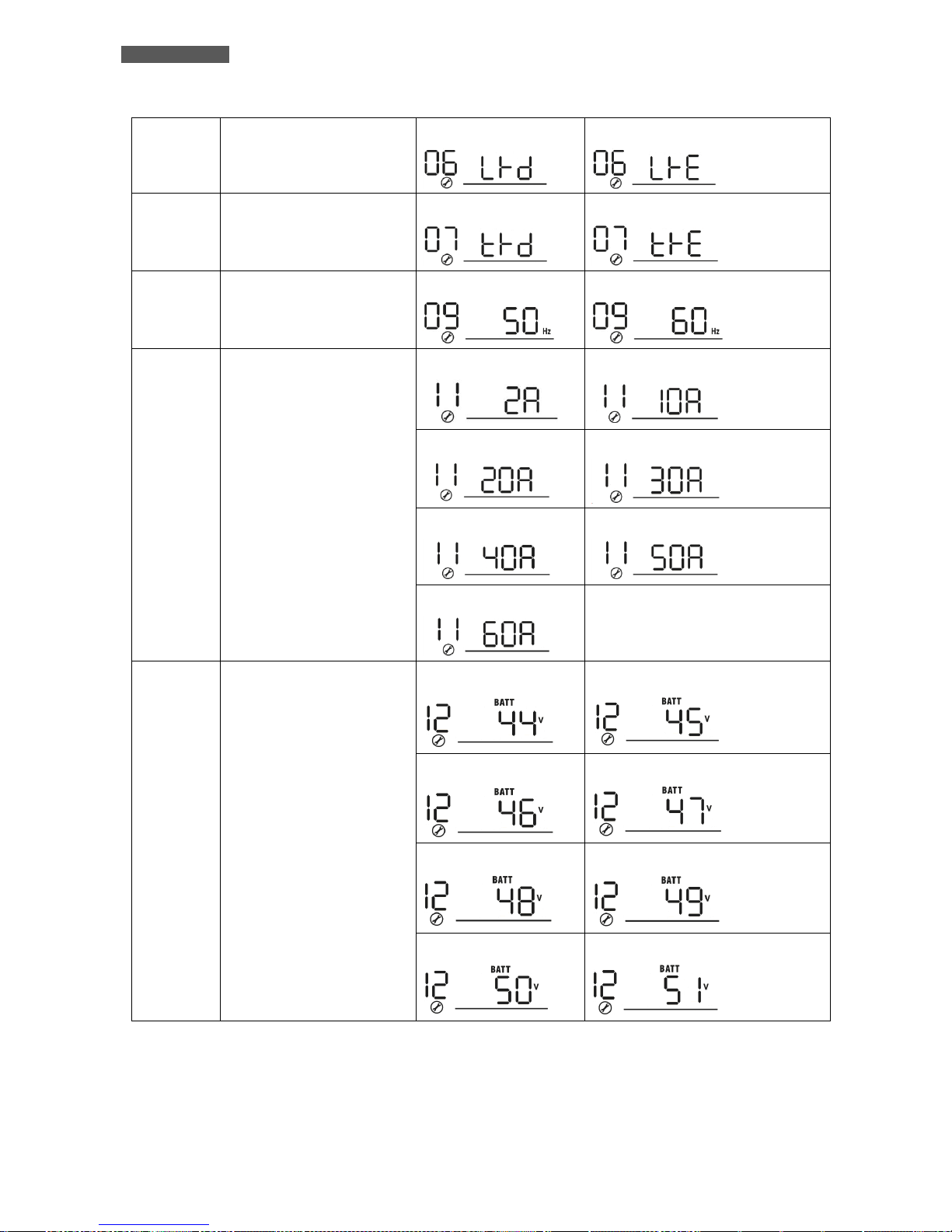
ENGLISH
User’s manual 50 ATA Energy Storage System MM
06
Auto restart when overload
occurs
Restart disable
Restart enable (default)
07
Auto restart when over
temperature occurs
Restart disable
Restart enable (default)
09
Output frequency
50Hz (default)
60Hz
11
Maximum utility charging
current
2A
10A
20A
30A (default)
40A
50A
60A
12
Pre-setting voltage back to
utility source when selecting
“Solar first” or “SBU priority”
in program 01.
44V
45V
46V (default)
47V
48V 49V
50V
51V
Page 57

ENGLISH
ATA Energy Storage System MM 51 User’s manual
13
Pre-setting voltage back to
battery mode when selecting
“Solar first” or “SBU priority”
in program 01.
48V
49V
50V (default)
51V
52V
53V
54V
55V
56V
57V 58V
Battery fully charged
16
Charger source priority:
To configure charger source
priority
If this inverter/charger is working in Line, Standby or Fault mode,
charger source can be programmed as below:
Solar first
Solar energy will charge battery as
first priority.
Utility will charge battery only when
solar energy is not available.
Utility first
Utility will charge battery as first
priority.
Solar energy will charge battery only
when utility power is not available.
Solar and Utility
Solar energy and utility will charge
battery at the same time.
Only Solar (default)
Solar energy will be the only charger
source no matter utility is available or
not.
If this inverter/charger is working in Battery mode or Power
saving mode, only solar energy can charge battery. Solar energy
will charge battery if it's available and sufficient.
Page 58
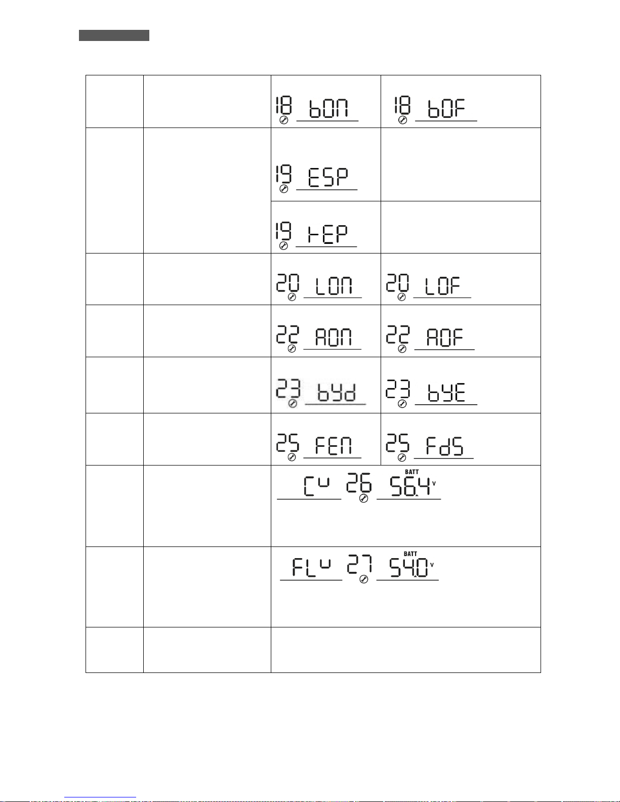
ENGLISH
User’s manual 52 ATA Energy Storage System MM
18
Buzzer Alarm
Alarm on
Alarm off (default)
19
Auto return to default display
screen
Return to default display
screen (default)
If selected, no matter how users
switch display screen, it will
automatically return to default
display screen (Input voltage /output
voltage) after no button is pressed for
1 minute.
Stay at latest screen
If selected, the display screen will
stay at latest screen user finally
switches.
20
Backlight control
Backlight on
Backlight off (default)
22
Beeps while primary source is
interrupted
Alarm on
Alarm off (default)
23
Overload bypass:
When enabled, the unit will
transfer to line mode if
overload occurs in battery
mode.
Bypass disable
Bypass enable (default)
25
Record Fault code
Record enable (default)
Record disable
26
Bulk charging voltage
(C.V voltage)
If user-defined is selected in program 5, this program can be set
up. Setting range is from 48.0V to 58.4V and increment of each
click is 0.1V.
27
Floating charging voltage
If user-defined is selected in program 5, this program can be set
up. Setting range is from 48.0V to 58.4V and increment of each
click is 0.1V.
28
AC output mode:
ATA can work in single,
parallel, phase S, phase R and
phase T mode.
Default is setted as Single mode.
For the other modes refer to sections 11.10 and 12.10.
Page 59
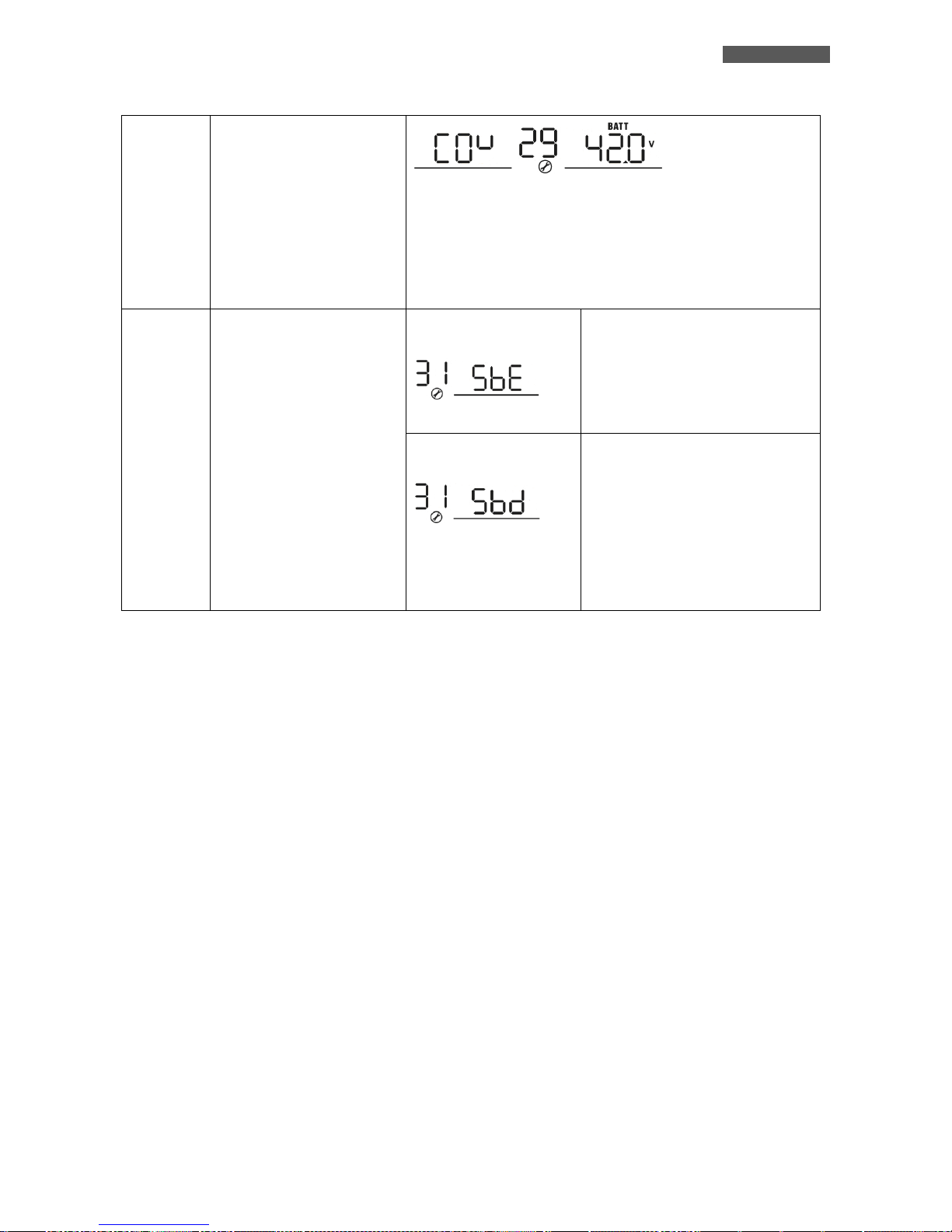
ENGLISH
ATA Energy Storage System MM 53 User’s manual
29
Low DC cut-off voltage
If user-defined is selected in program 5, this program can be set
up. Setting range is from 40.0V to 48.0V and increment of each
click is 0.1V. Low DC cut-off voltage will be fixed to setting value
no matter what percentage of load is connected. Then, low DC
warning voltage is 2V higher than cut-off voltage, low DC warning
return voltage is 4V higher than cut-off voltage and Cold Start
Voltage is 4V higher than cut-off voltage.
31
Solar power balance:
When enabled, solar input
power will be automatically
adjusted according to
connected load power.
(Only available for
4KVA/5KVA model)
“Solar Power Balance”
enable (default):
If selected, solar input power will be
automatically adjusted according to
the following formula:
Max. input solar power = Max.
battery charging power + Connected
load power.
“Solar Power Balance”
disable:
If selected, the solar input power
will be the same to max. battery
charging power no matter how much
loads are connected. The max.
battery charging power will be based
on the setting current in program
02.
(Max. solar power = Max. battery
charging power)
Page 60
ENGLISH
User’s manual 54 ATA Energy Storage System MM
15 Maintenance
15.1 ATA Cleaning
Before starting any cleaning operation, be sure that:
1. The AC Input Voltage for the ATA has been removed.
2. The Battery voltage for ATA has been removed.
3. The PV voltage for ATA has been removed.
4. The ATA is completely OFF.
Use only a cloth dampened with water to clean the unit.
If ATA works in an environmental unusually dusty or dirty, remove the dirty from the ventilation holes.
Before restarting the ATA be sure it is completely dry. If any liquid gets inside the ATA, do not start the unit and
contact Technical Service immediately.
15.2 Battery
If the ATA is NOT going to be used for a long period of time, ensure that the batteries are left fully charged.
If the ATA has not been used for more than three months, go through the procedure described in the chapter “First
Start Up” before using it again.
Battery life strongly depends on the ambient temperature. There are also other factors like the number of chargedischarge cycles, the discharge depth, humidity and altitude.
The recommended environmental specifications for a correct use of batteries are listed in battery producer data
sheet.
Danger of explosion and fire if batteries of the wrong type or number are used.
Do not dispose of batteries in a fire. The batteries may explode. Do not open or mutilate
batteries. Released electrolyte is harmful to the skin and eyes. It may be toxic.
15.3 Operator Safety
Whenever the ATA is not responding anymore to original characteristics, the ATA must be made non-operative and
every usage not authorised must be avoided. After it will be necessary to refer to qualified technical personnel.
Original safety characteristics might not be if, for example, the ATA has visible damage or irregular operation.
Page 61
ENGLISH
ATA Energy Storage System MM 55 User’s manual
16 Troubleshooting
This section gives information about the procedures which shall be performed in case of abnormal operation.
If you fail to fix the problem consult authorized Technical Service with the following information:
Model and serial number of the ATA, which can be found on the nameplate on the side of the ATA.
Description of abnormal operation and Fault code displayed on graphic LCD.
If you have noticed an abnormality in operation; check the Protective Ground/Earth connections, check the
Input/Output connections, read alarms code from the graphic LCD and refer to the table below. Apply all suggestions
corresponding to each anomaly.
If your issue is excluded or the suggested actions do not solve your problem, consult the Technical Service.
Risk of electric shock: do not remove the cover. The ATA contains internal parts which
are at a high Voltage and are potentially dangerous, capable of causing injury or death
by electric shock.
There are no internal parts in the ATA which are user serviceable. Any repair or
maintenance work must be performed exclusively by qualified technical personnel
authorized by TECNOWARE.
TECNOWARE declines any responsibility if this warning is disregarded.
SYMPTOM
LCD/LED/BUZZER
POSSIBLE CAUSE
ACTION TO SOLVE
ATA shutdown
automatically during
startup process.
LCD, LEDs and buzzer will
be active for 3 seconds
and then complete off.
The battery voltage is too
low.
1. Re-charge battery.
2. Contact Technical
Service.
No response after power
on.
No indication.
1. The battery voltage is
far too low.
2. Battery polarity is
connected reversed.
1. Check if batteries and
the wiring are connected
well.
2. Re-charge battery.
3. Contact Technical
Service.
When the unit is turned
on, internal relay is
switched on and off
repeatedly.
LCD display and LEDs are
flashing
Batteries are
disconnected.
Check if battery wires are
connected well.
Page 62
ENGLISH
User’s manual 56 ATA Energy Storage System MM
SYMPTOM
LCD/LED/BUZZER
POSSIBLE CAUSE
ACTION TO SOLVE
Buzzer beeps continuously
and red LED is on.
Fault code 07
Overload error.
Reduce the connected
load by switching off some
equipment.
Fault code 05
Output short circuited.
Check if wiring is
connected well and
remove abnormal load.
Temperature of internal
converter component is
over 120°C.
Check whether the air
flow of the unit is blocked
or whether the ambient
temperature is too high.
Fault code 02
Internal temperature of
inverter component is
over 100°C.
Fault code 03
Battery is over-charged.
Contact Technical
Service.
The battery voltage is too
high.
Check if spec and quantity
of batteries are meet
requirements.
Fault code 01
Fan fault
Contact Technical
Service.
Fault code 06/58
Output abnormal (Inverter
voltage below than 190Vac
or is higher than 260Vac)
1. Reduce the connected
load.
2. Contact Technical
Service.
Fault code 08/09/53/57
Internal components
failed.
Contact Technical
Service.
Fault code 51
Over current or surge.
Restart ATA, if the error
happens again, please
contact Technical Service.
Fault code 52
Bus voltage is too low.
Fault code 55
Output voltage is
unbalanced.
Fault code 56
Battery is not connected
well or fuse is burnt.
If the battery is connected
well, please contact
Technical Service.
If the described anomalies should continue despite the advised troubleshooting, or should they
manifest in any other form, please contact:
TECNOWARE SERVICE
www.tecnoware.com
Page 63
ENGLISH
ATA Energy Storage System MM 57 User’s manual
Conformity to the European Directives
TECNOWARE S.r.l. confirms that ATA ENERGY STORAGE SYSTEM models comply with the requirements set out in: the Low
Voltage (Safety) Directive 2014/35/EU and following amendments, the EMC (Electro-Magnetic Compatibility) Directive
2014/30/EU and following amendments.
Product Disposal
ATA ENERGY STORAGE SYSTEM cannot be disposed as an urban waste, but must be treated as a separate
waste. Any violation is indictable with financial sanctions as per in force regulations.
An incorrect waste disposal or an improper use of the same or of any parts can be damaging for the
environment and for human health.
A correct waste disposal of products having the dustbin symbol marked by a cross help to avoid negative
consequences to the environment and to human health.
Lead Batteries
ATA ENERGY STORAGE SYSTEM models contain lead acid, sealed, maintenance free batteries.
This kind of batteries, if handled by non-experienced personnel, can cause electric shock or shortcircuit.
For this reason the batteries can be removed only by qualified technical personnel, specialized and
authorized by Tecnoware. Tecnoware declines any responsibilities if this rule is not followed.
To remove the batteries, firstly you have to take off ATA cover, then remove all the metallic parts that
are blocking the batteries pack, disconnect batteries one to each other and take them off from their
housing one by one.
The batteries cannot be disposed as an urban waste, but must be treated in conformity with 2006/66/CE
European Directive; any violation is indictable with financial sanctions as established into 2006/66/CE
European Directive.
Page 64

ENGLISH
User’s manual 58 ATA Energy Storage System MM
Page 65
ITALIANO
ATA Energy Storage System MM 59 Manuale utente
Manuale Utente – Italiano
Avvisi di Sicurezza
Leggere attentamente e completamente questo manuale prima di installare ATA ENERGY
STORAGE SYSTEM, che in seguito verrà chiamato anche semplicemente ATA.
L'ATA deve essere utilizzato solo da personale opportunamente istruito. Per l’uso corretto e
in condizioni di sicurezza è necessario che gli operatori ed il personale di manutenzione si
attengano alle norme generali di sicurezza, in aggiunta alle norme specifiche contenute in
questo manuale.
Rischio di shock elettrico: non rimuovere il coperchio. L’ATA presenta parti interne sotto
tensione che sono potenzialmente pericolose e possono provocare lesioni o morte per shock
elettrico.
L’ATA non ha parti interne soggette a manutenzione da parte dell’utente. Interventi tecnici di
qualsiasi tipo devono essere compiuti solo da personale tecnico specializzato ed autorizzato
da TECNOWARE. In caso contrario TECNOWARE declina ogni sua responsabilità.
L'installazione elettrica, nonostante la sua semplicità, deve essere eseguita esclusivamente da
elettricisti qualificati. Seguire scrupolosamente tutte le norme locali e nazionali (in ITALIA le
norme CEI) per le connessioni d'Ingresso/Uscita e per il corretto dimensionamento dei cavi
d'Ingresso/Uscita in rapporto alla potenza nominale.
Il collegamento a terra dell’ATA secondo le norme vigenti è obbligatorio.
Rischio di shock elettrico in Uscita se l’ATA è acceso.
Rischio di shock elettrico in Uscita se è presente la Tensione di Rete elettrica in Ingresso.
Per rispetto alle norme di sicurezza è necessario l'inserimento di un interruttore differenziale
a valle dell’Uscita dell’ATA.
Destinare all'ATA una propria linea elettrica di potenza.
Non ostruire le fessure o i fori di ventilazione e non appoggiare alcun oggetto sopra l’ATA.
Non inserire oggetti o versare liquidi nei fori di ventilazione.
Installare l’ATA in ambiente chiuso, pulito e privo di umidità.
Non esporre l’ATA alla luce diretta del sole.
Non avvicinare liquidi, gas infiammabili o sostanze corrosive.
Page 66
ITALIANO
Manuale utente 60 ATA Energy Storage System MM
1 Introduzione
L’ATA ENERGY STORAGE SYSTEM è il risultato di una costante ricerca tecnologica mirata all'ottenimento delle
migliori prestazioni a costi estremamente contenuti.
ATA ENERGY STORAGE SYSTEM è un inverter con accumulo e funzione UPS monofase ad onda sinusoidale
progettato per alimentare e proteggere le più sofisticate apparecchiature elettroniche: infatti, fornisce
un'alimentazione assolutamente continua, regolata e priva di disturbi di qualsiasi tipo (black-out, sottotensioni,
sovratensioni, surge, spike, microinterruzioni, interferenze).
La sicurezza per le utenze alimentate è garantita anche in caso di sovraccarico accidentale oppure di guasto
inverter, grazie ad un Bypass automatico che esclude ATA ENERGY STORAGE SYSTEM e collega direttamente la
linea elettrica d’Ingresso alle uscite.
ATA ENERGY STORAGE SYSTEM è dotato d’interfacce di comunicazione RJ45/RS232 e USB che possono essere
utilizzate per la comunicazione con il programma WatchPower.
Leggere attentamente questo manuale prima di utilizzare ATA ENERGY STORAGE
SYSTEM perché contiene importanti avvisi di sicurezza per l'operatore ed utili consigli
per un corretto impiego.
ATA ENERGY STORAGE SYSTEM è soggetto a continui sviluppi e migliorie: di conseguenza può differire lievemente,
in alcuni dettagli, da quanto descritto nel presente manuale.
Questo manuale è relativo ai seguenti modelli:
ATA Energy Storage System 4.0 MM (4000VA, 3200W, 3750Wp max da PV)
ATA Energy Storage System 5.0 MM (5000VA, 4000W, 3750Wp max da PV)
In questo manuale ATA ENERGY STORAGE SYSTEM sarà chiamato anche semplicemente ATA.
I modelli ATA ENERGY STORAGE SYSTEM sono costituiti da un’unità singola che contiene l’elettronica interna.
I modelli ATA ENERGY STORAGE SYSTEM necessita per il funzionamento del collegamento con unità Box Batterie.
Page 67
ITALIANO
ATA Energy Storage System MM 61 Manuale utente
2 Caratteristiche Generali
ATA ENERGY STORAGE SYSTEM presenta tutte le moderne caratteristiche che garantiscono massima affidabilità e
sicurezza:
1. Inverter OFF-GRID con sistema di accumulo
2. Uscita sinusoidale pura
3. Sistema MPPT Integrato per la ricerca del miglior punto di lavoro
4. Diverse modalità di funzionamento selezionabili
5. Corrente di ricarica selezionabile
6. Priorità di ricarica selezionabili
7. Frequenza d’uscita impostabile
8. Display LCD grafico per visualizzazione delle misure della Tensione d’Ingresso e d’Uscita, Tensione
batterie, percentuale di potenza utilizzata, frequenza, allarmi, guasti e dei vari modi di funzionamento
9. Configurazione e settaggio da parte dell’utente dei parametri di funzionamento tramite pannello frontale
e display grafico o tramite software installato su PC
10. Segnalazioni acustiche di vario tipo durante il normale funzionamento e che evidenziano le eventuali
condizioni di allarme
11. Sistema di ricarica delle batterie gestito da microprocessore
12. Espandibilità fino a 4 unità in parallelo (opzionale)
13. Protezione dal sovraccarico e dal cortocircuito
14. Accensione anche in condizioni di Assenza Rete
15. Protezione automatica in caso di batterie scariche
16. Riaccensione automatica dopo lo spegnimento per fine autonomia al ritorno della Tensione di Rete
17. Porta di comunicazione RJ45/RS232 e USB
18. Elevato rendimento e basso costo d'esercizio
19. Alta affidabilità
20. Curato design e semplicità d’uso
Page 68
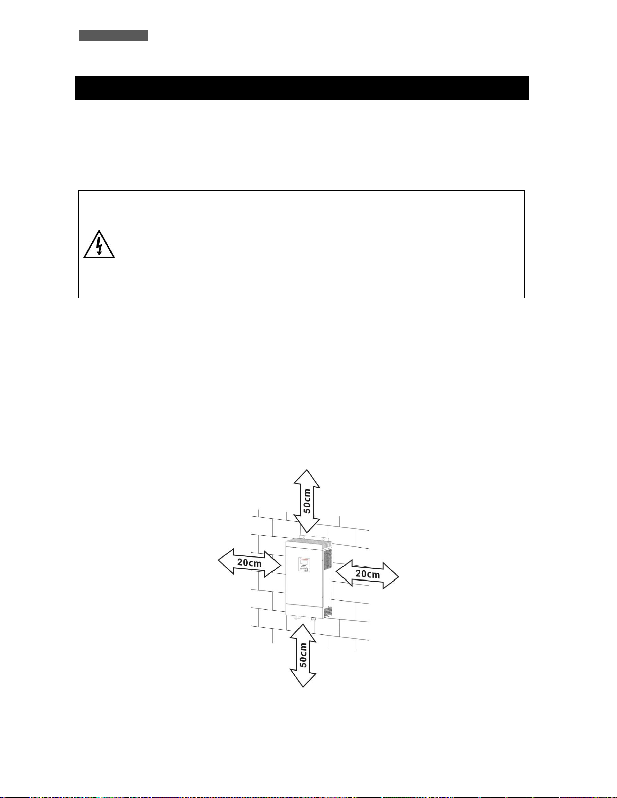
ITALIANO
Manuale utente 62 ATA Energy Storage System MM
3 Ricevimento e Collocazione
Al ricevimento dell’ATA, si consiglia di togliere subito l'imballo e di controllare lo stato dell'ATA. In caso di danni
dovuti al trasporto, annotarli sulla bolla di accompagnamento merce e contattare subito il fornitore.
Si consiglia di conservare l’imballo originale in luogo sicuro.
Si consiglia di prestare attenzione ai punti seguenti per la scelta di una corretta collocazione dell’ATA:
L'installazione deve essere eseguita esclusivamente da personale qualificato.
ATTENZIONE: porre attenzione a collocare l’ATA su di una superficie che sia in grado di
sostenere le caratteristiche meccaniche (peso e dimensioni) riportate nel capitolo
“Caratteristiche Tecniche”.
ATTENZIONE: porre attenzione nell’utilizzare un sistema di fissaggio adeguato alla
superficie di installazione e al peso dell’ATA.
In caso contrario TECNOWARE declina ogni sua responsabilità.
1. L'ATA è progettato per operare in ambienti chiusi. Si consiglia perciò d’installarlo in un luogo privo di
umidità, polvere e fumo eccessivi.
2. Se l’ATA deve essere spostato da un luogo freddo ad un luogo più caldo, l’umidità dell’aria può causare
condensazione all’interno dell’ATA. In tal caso lasciare l’ATA nel luogo più caldo per circa 2 ore prima di
cominciare la procedura d’installazione.
3. Consultare comunque il capitolo “Caratteristiche Tecniche” per i requisiti ambientali e controllare che il
luogo scelto rientri in tali specifiche.
4. Durante il normale funzionamento l’ATA emette una quantità minima di calore. È perciò necessario
lasciare uno spazio libero di almeno 20 cm lateralmente e 50 cm sopra e sotto all’ATA per permetterne
una sufficiente areazione. Fare riferimento all’immagine sottostante.
Page 69
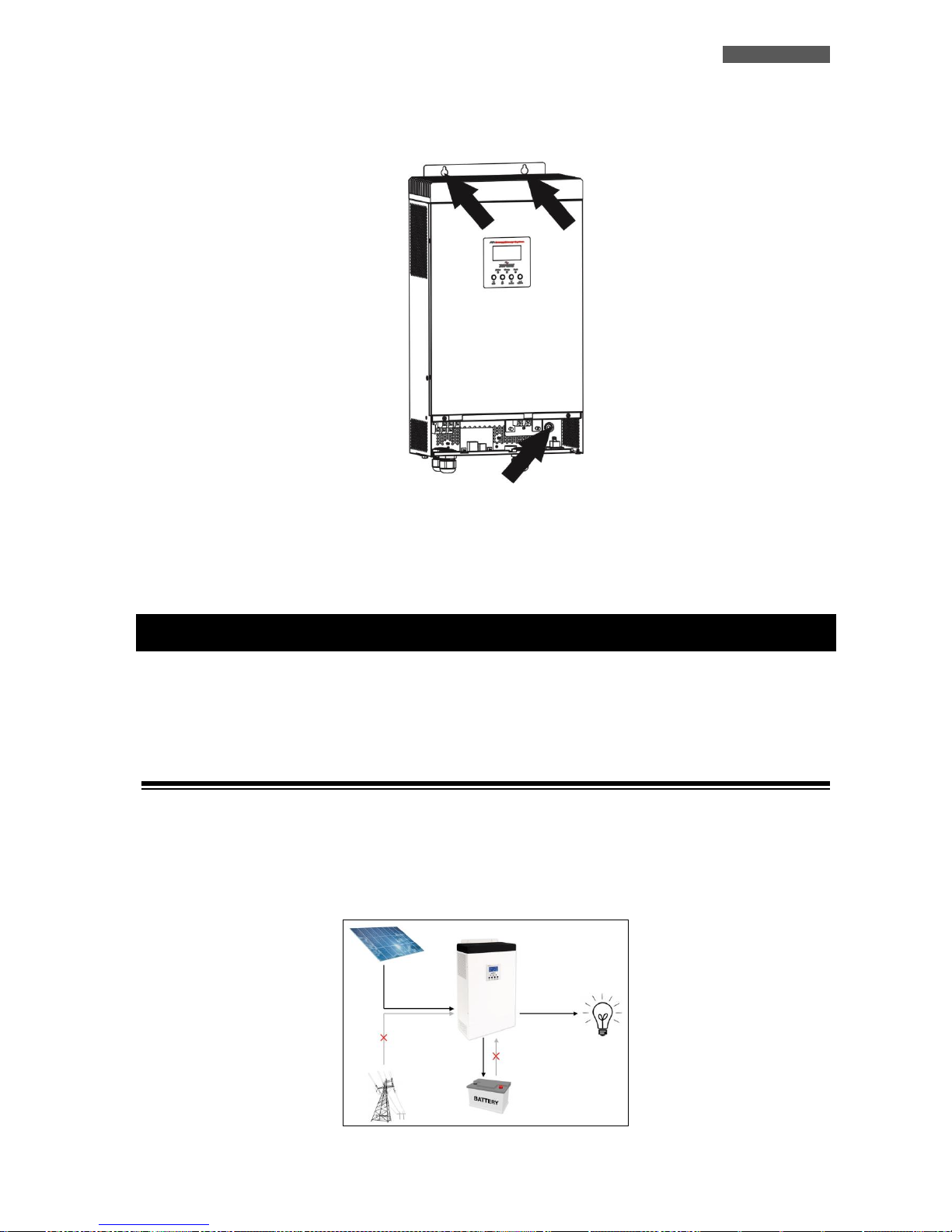
ITALIANO
ATA Energy Storage System MM 63 Manuale utente
5. Fissare l’ATA sulla superficie scelta, tramite l’utilizzo di tasselli e viti. Fare riferimento alla figura
sottostante per i punti di fissaggio predisposti a bordo dell’ATA.
6. Non ostruire le fessure o i fori di ventilazione.
7. Non inserire oggetti o versare liquidi nei fori di ventilazione.
8. Non appoggiare alcun oggetto sopra l’ATA.
9. Non avvicinare liquidi, gas infiammabili o sostanze corrosive.
4 Funzionamento
La modalità tipica di funzionamento è la modalità SBU: la sigla SBU indica l’ordine di priorità della fonte di
alimentazione utilizzata da ATA. La prima fonte è S = SOLAR. cioè i pannelli fotovoltaici, la seconda fonte è B =
BATTERY, cioè le batterie, la terza fonte è U = UTILITY, cioè la rete elettrica.
4.1 Modalità SBU: funzionamento con Pannelli Attivi
Le apparecchiature vengono alimentate dal sistema ATA utilizzando l’energia dei pannelli fotovoltaici. In questa
fase ATA carica contemporaneamente le batterie e funziona in maniera autonoma senza la necessità di utilizzare
la rete elettrica. ATA è dotato di un sistema MMPT (Maximum Power Point Tracker) che permette di trovare il
miglior punto di lavoro per sfruttare al massimo la potenza dei pannelli solari, in base all’irraggiamento a cui
sono esposti.
Page 70
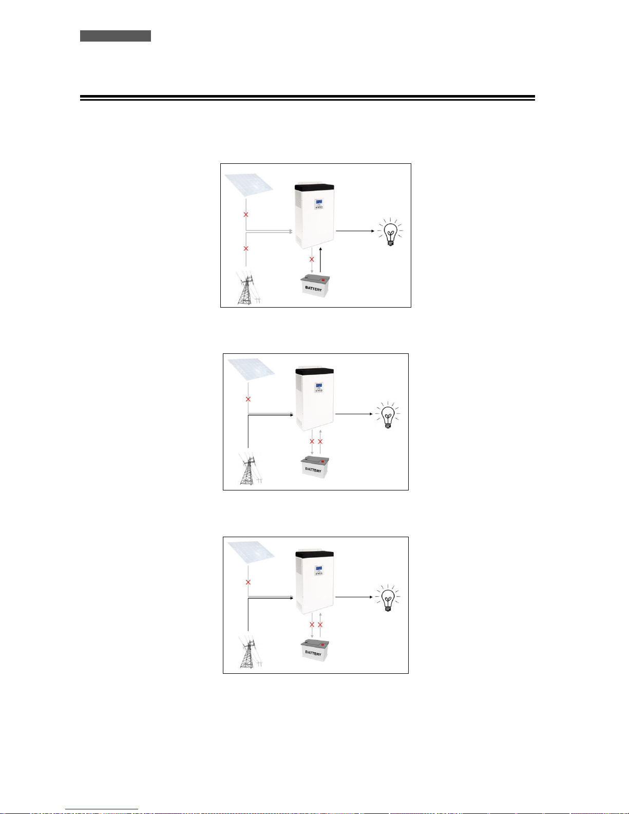
ITALIANO
Manuale utente 64 ATA Energy Storage System MM
4.2 Modalità SBU: funzionamento con Pannelli non Attivi
Le apparecchiature vengono alimentate dal sistema ATA utilizzando l’energia accumulata nelle batterie fino a
quando i pannelli fotovoltaici si attivano nuovamente. L’energia stoccata può essere utilizzata fino ad una soglia
minima del 30/40% (valore impostabile tramite settaggi).
Solo nel caso in cui questa energia non sia sufficiente, le apparecchiature vengono alimentate automaticamente
dalla rete elettrica. In questa fase le batterie non vengono ricaricate dalla rete elettrica.
Se in questa fase si verifica un black-out, ATA utilizza il 30/40% di energia residua delle batterie (funzione UPS)
per alimentare le apparecchiature.
Esaurita anche l’energia residua il sistema si spenge. Quando la rete elettrica o i pannelli fotovoltaici si riattivano
il sistema ATA Energy Storage System si riavvia automaticamente.
Quando il livello di carica delle batterie raggiunge il valore di soglia impostati, ATA Energy Storage System
commuta automaticamente nella modalità pannelli attivi (vedi punto 4.1).
Page 71
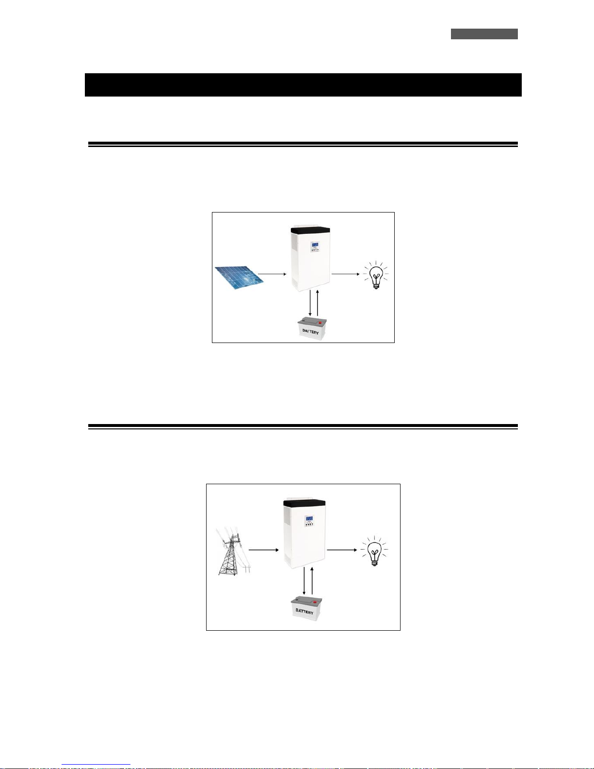
ITALIANO
ATA Energy Storage System MM 65 Manuale utente
5 Altri Modi di Funzionamento
5.1 Modalità Only Solar: solo con Pannelli Fotovoltaici
ATA utilizza l’energia dei pannelli fotovoltaici per alimentare le apparecchiature e contemporaneamente carica
le batterie. Nel caso in cui l’energia dei pannelli fotovoltaici sia insufficiente ATA utilizza l’energia delle
batterie.
Per attivare questa modalità è necessario entrare nei settaggi di ATA e impostare correttamente i parametri 01 e
16. Vedere capitolo “Settaggi”.
5.2 Modalità Utility: solo con la Rete Elettrica
ATA utilizza l’energia della rete elettrica per alimentare le apparecchiature e contemporaneamente carica le
batterie. Nel caso in cui l’energia della rete sia assente ATA utilizza l’energia delle batterie.
Per attivare questa modalità è necessario entrare nei settaggi di ATA e impostare correttamente i parametri 01 e
16. Vedere capitolo “Settaggi”.
Page 72
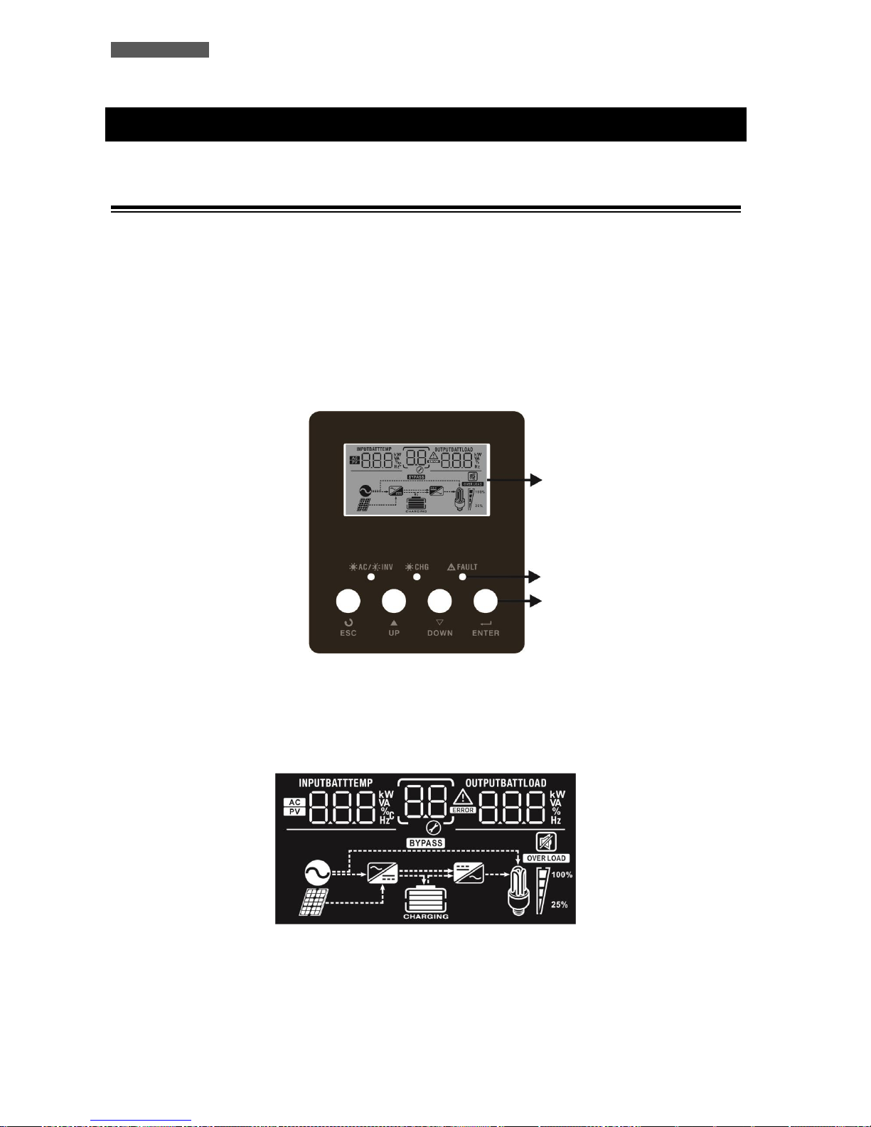
ITALIANO
Manuale utente 66 ATA Energy Storage System MM
6 Descrizione Esterna
6.1 Pannello Frontale
Il pannello frontale informa l’utente sullo stato di funzionamento, sulle condizioni di allarme e sulle misure.
Inoltre consente di controllare e configurare i parametri di funzionamento.
Il pannello frontale, mostrato nella figura 1, è costituito da 2 parti:
1. Un pannello LCD grafico che fornisce le informazioni complete sullo stato di funzionamento per i vari modi
di funzionamento, sugli allarmi esistenti, sul carico in Uscita, sulle batterie, e sulle misure delle grandezze
elettriche della linea d’Ingresso, d’Uscita e delle batterie.
2. 4 pulsanti che permettono di attivare e disattivare l’ATA, svolgere altre funzioni e fare la selezione dei
parametri di funzionamento.
Figura 1 – Pannello Frontale
6.1.1 Pannello LCD Grafico
Prego riferirsi alla figura 2.
Figura 2 – Pannello LCD grafico
LCD display
LED
Pulsanti
Page 73
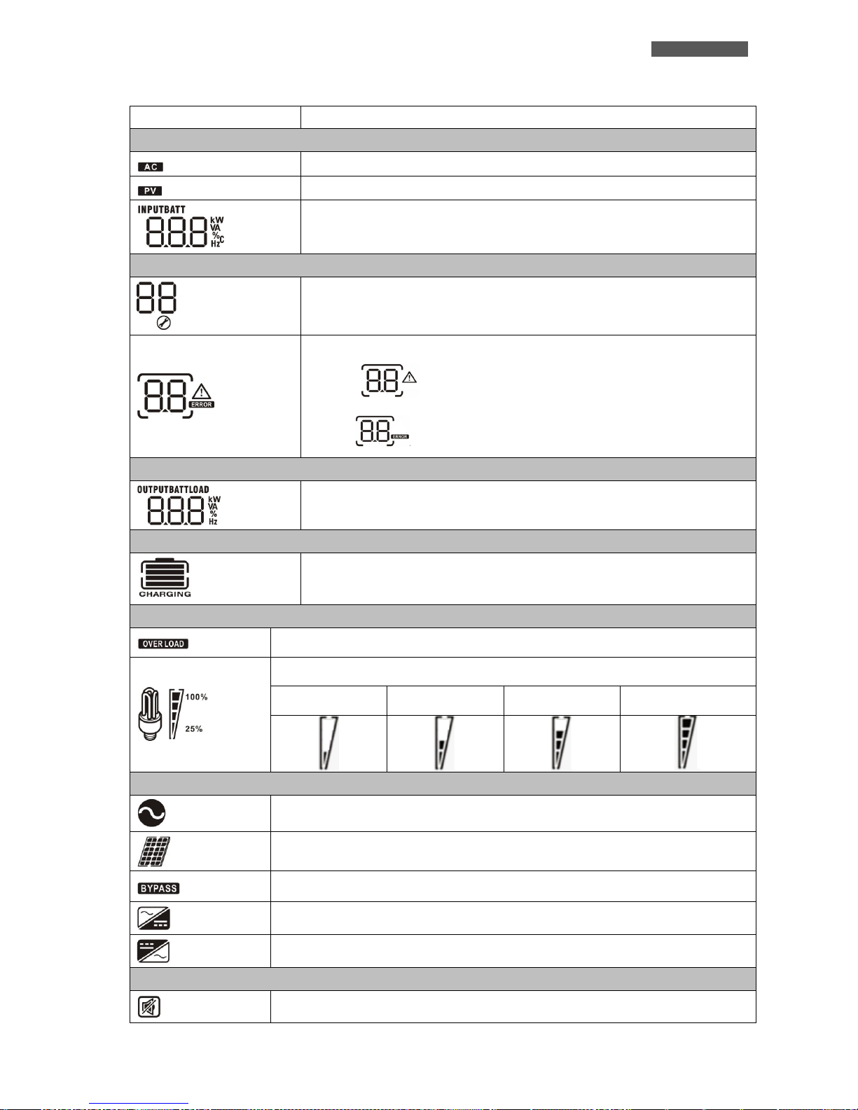
ITALIANO
ATA Energy Storage System MM 67 Manuale utente
Pannello LCD Grafico
Funzione
Ingresso
Indica la rete d’ingresso.
Indica l’alimentazione da pannelli fotovoltaici.
Indica tensione d’ingresso, frequenza d’ingresso, tensione pannelli PV, tensione
batterie e corrente di ricarica.
Settaggi ed errori/allarmi
Indica il numero del settaggio.
Indica il codice di allarme e di errore.
Allarme: lampeggia il numero del codice di allarme.
Errore: viene visualizzato il numero del codice di allarme.
Uscita
Indica la tensione di uscita, frequenza di uscita, percentuale di carico, carico
espresso in VA e in Watt.
Batterie
Indica il livello batterie da 0-24%, 25-49%, 50-74% e 75-100% in modalità batteria
e in fase di ricarica in modalità rete/pannelli fotovoltaici.
Carico
Indica sovraccarico.
Indica il livello del carico da 0-24%, 25-50%, 50-74% e 75-100%.
0%~25%
25%~50%
50%~75%
75%~100%
Modalità di funzionamento
Indica la connessione alla rete elettrica.
Indica la connessione ai pannelli fotovoltaici.
Indica che il carico è alimentato dalla rete elettrica (bypass).
Indica che il circuito carica batterie è attivo.
Indica che il circuito inverter è attivo.
Mute Operation
Indica che l’allarme acustico è disabilitato.
Page 74
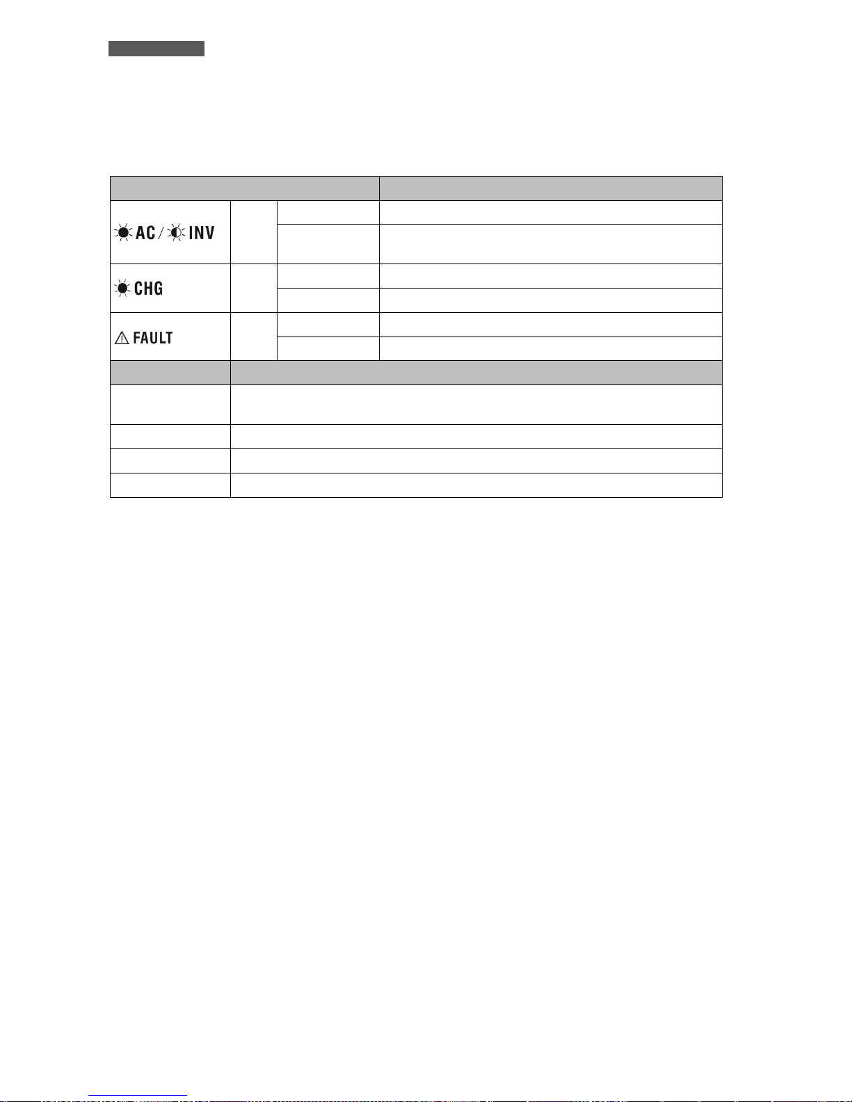
ITALIANO
Manuale utente 68 ATA Energy Storage System MM
6.1.2 Led e Pulsanti
Le funzioni dei led e dei pulsanti presenti sul pannello frontale sono riportate sotto:
LED
Messaggio
Verde
Fisso
L’uscita è alimentata dalla rete elettrica.
Lampeggiante
L’uscita è alimentata dai pannelli fotovoltaici o dalle
batterie.
Verde
Fisso
Batterie completamente cariche.
Lampeggiante
Batterie in carica.
Rosso
Fisso
Guasto o problematica su ATA.
Lampeggiante
Allarme su ATA.
Pulsante
Descrizione
ENTER
Premere per 3 secondi per accedere alle impostazioni. Premere per confermare la
selezione nelle impostazioni
ESC
Per uscire dalle impostazioni
UP
Per accedere alla precedente selezione
DOWN
Per accedere alla successiva selezione
Page 75
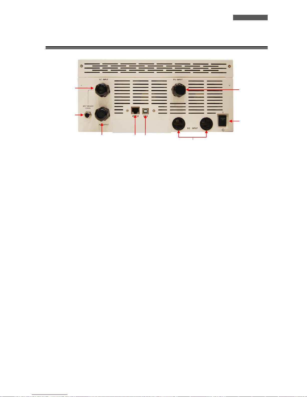
ITALIANO
ATA Energy Storage System MM 69 Manuale utente
6.2 Pannello Posteriore
Figura 3 – Pannello Posteriore
1. Interruttore On/Off: per accendere e spengere ATA.
2. Morsettiera d’ingresso con terra: per connettere ATA alla rete elettrica.
3. Ingresso pannelli PV: per connettere ATA ai pannelli fotovoltaici.
4. Ingresso batterie: per connettere ATA alle batterie.
5. Interruttore termico d’ingresso rete: l’interruttore scatta in caso di sovraccarico o cortocircuito; per
riarmare l’interruttore occorre premere manualmente sulla parte fuoriuscita.
6. Morsettiera di uscita con terra: per alimentare il carico.
7. Interfaccia di comunicazione (connettore RJ45/RS232): è la porta di comunicazione RJ45/RS232 (tramite
il cavo RJ45-RS232).
8. Interfaccia di comunicazione (connettore USB): è la porta di comunicazione USB.
1
2
3
5 6 4 7 8
Page 76
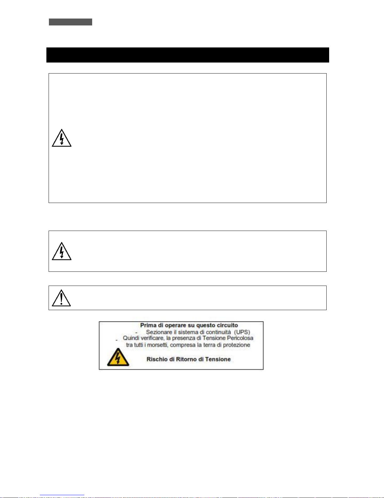
ITALIANO
Manuale utente 70 ATA Energy Storage System MM
7 Installazione Elettrica
L'installazione elettrica, deve essere eseguita esclusivamente da elettricisti qualificati.
Seguire scrupolosamente tutte le norme locali e nazionali (in ITALIA le norme CEI) per
le connessioni d'Ingresso e d’Uscita e per il corretto dimensionamento dei cavi
d'Ingresso e d’Uscita.
Per la sicurezza degli operatori occorre posizionare degli interruttori esterni tra la
linea elettrica d’Ingresso e la linea d’Ingresso dell’ATA (consigliato interruttore
differenziale da 300mA), e tra la linea d’Uscita dell’ATA e i dispositivi da alimentare
con differenziali da 30mA. Gli interruttori hanno la funzione di protezione e sicurezza
e devono essere installati secondo le norme vigenti.
Inoltre è opportuno installare un quadro di campo tra la linea dei pannelli fotovoltaici
e l’ingresso dei pannelli fotovoltaici sull’ATA, dimensionato in base alla linea di
pannelli fotovoltaici installata.
Per i collegamenti d’Ingresso/Uscita utilizzare esclusivamente cavi con caratteristiche
conformi a quelle riportate nella tabella sottostante.
In caso contrario TECNOWARE declina ogni sua responsabilità.
I modelli ATA ENERGY STORAGE SYSTEM sono costituiti da un’unità che contiene l’elettronica. Le batterie sono
installate esternamente.
Prima di avviare la procedura d'installazione, accertarsi che:
1. La linea elettrica d’Ingresso, la linea dei pannelli fotovoltaici e il pacco batterie
siano disattivi.
2. L’ATA sia completamente spento.
E’ necessario applicare un avvertenza, come quella riportata sotto, all’interno del
quadro di distribuzione AC d’ingresso e d’uscita.
Page 77
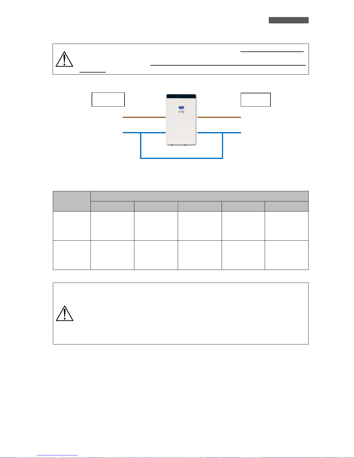
ITALIANO
ATA Energy Storage System MM 71 Manuale utente
Quando ATA lavora con i pannelli fotovoltaici e/o le batterie, il Neutro non è passante.
Per ricreare in uscita lo stesso sistema d’alimentazione d’ingresso (rete di
alimentazione elettrica), il neutro d’uscita deve essere connesso con il neutro
d’ingresso. Fare riferimento all’immagine sotto riportata.
La seguente tabella indica Ie specifiche raccomandate, dei cavi da utilizzare per i collegamenti.
I cavi di ATA 4.0 MM devono essere dimensionati per sopportare correnti fino a 29A in
ingresso rete, 60A in ingresso pannelli fotovoltaici, 75A dalle batterie e 18A in uscita.
Per sicurezza e affidabilità occorre utilizzare cavi con sezione non inferiore a quelli
indicati nella tabella sopra riportata.
I cavi di ATA 5.0 MM devono essere dimensionati per sopportare correnti fino a 29A in
ingresso rete, 60A in ingresso pannelli fotovoltaici, 93A dalle batterie e 22A in uscita.
Per sicurezza e affidabilità occorre utilizzare cavi con sezione non inferiore a quelli
indicati nella tabella sopra riportata.
Modello
Specifica del cavo (sezione mm2 - AWG)
Input
Pannelli PV
Batterie
Output
Ground
ATA 4.0 MM
6 mm
2
o 10
AWG
8 mm
2
o 8 AWG
2 x 8 mm
2
o 2
x8 AWG (2 cavi
uniti con un
unico capocorda)
6 mm
2
o 10
AWG
6 mm
2
o 10
AWG
ATA 5.0 MM
8 mm
2
o 8 AWG
8 mm
2
o 8 AWG
2 x 8 mm
2
o 2
x8 AWG (2 cavi
uniti con un
unico capocorda)
8 mm
2
o 8 AWG
8 mm
2
o 8 AWG
INGRESSO
USCITA
FASE
FASE
NEUTRO
NEUTRO
Page 78
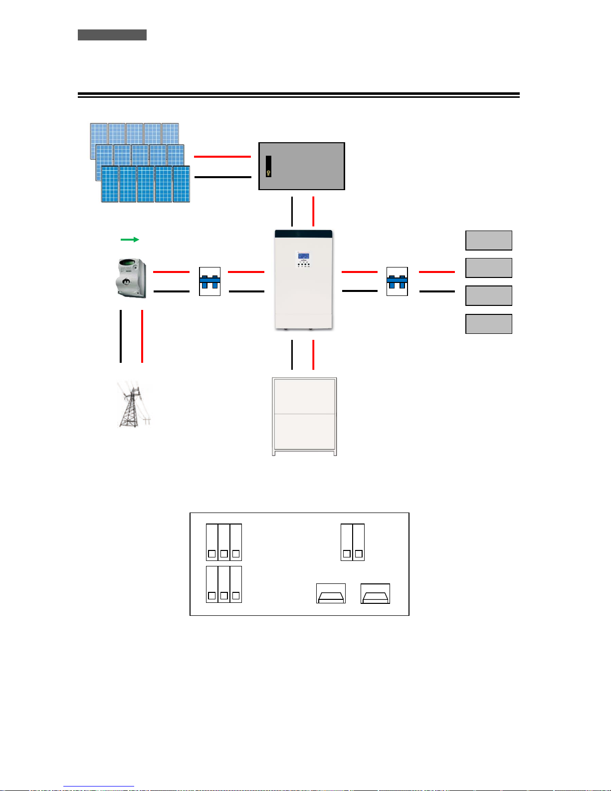
ITALIANO
Manuale utente 72 ATA Energy Storage System MM
7.1 Installazione
Figura 4 – Installazione e Connessioni ATA
ON
OFF
ON
OFF
CARICO
INTERRUTTORE
MAGNETOTERMICO
DIFFERENZIALE
30mA (GIA'
INTERRUTTORE
MAGNETOTERMICO
DIFFERENZIALE
CONTATORE (GIA’
ESISTENTE)
QUADRO DI CAMPO
PANNELLI
FOTOVOLTAICI
ATA ENERGY
STORAGE SYSTEM
BOX BATTERIE ATA
RETE
D’ALIMENTAZIONE
ELETTRICA
CONNESSIONI SU ATA ENERGY STORAGE SYSTEM
+ BATTERIE
- BATTERIE
G L N
G L N
INGRESSO RETE ATA
USCITA ATA
INGRESSO PANNELLI FOTOVOLTAICI
PV+
PV-
Page 79
ITALIANO
ATA Energy Storage System MM 73 Manuale utente
Per una corretta installazione svolgere le seguenti operazioni:
1. Collegare la linea d’Ingresso dell’ATA alla rete di alimentazione elettrica che deve avere obbligatoriamente
una connessione a terra secondo le norme vigenti. Verificare accuratamente il collegamento a terra della
rete d’alimentazione elettrica. Per la sicurezza degli operatori, occorre installate un interruttore di
protezione differenziale (consigliato di valore pari a 300mA) tra la rete di alimentazione elettrica e la linea
d’ingresso dell’ATA (vedi figura 4).
2. Collegare la linea di pannelli fotovoltaici all’ATA (vedi figura 4). E’ necessario porre attenzione nel collegare
i pannelli in modo tale da rispettare le specifiche riportare al capitolo “Caratteristiche Tecniche”.
2.1 Ogni serie di pannelli non deve superare la tensione massima a circuito aperto di 145VOC.
2.2 La potenza di picco installabile dai pannelli fotovoltaici è di 3750Wp.
2.3 Quindi, ipotizziamo di utilizzare dei pannelli da 250Wp con tensione nominale di 37,7Vdc. Sarà
possibile realizzare un impianto tipo il seguente:
2.3.1 Utilizzando pannelli fotovoltaici con tensione nominale pari a 37,7Vdc sarà possibile realizzare una
serie con massimo 3 pannelli fotovoltaici in quanto:
3 x 37,7 = 113,1Vdc cioè inferiore alla tensione massima a circuito aperto di 145Voc.
2.3.2 Utilizzando pannelli fotovoltaici con potenza pari a 250Wp, sarà possibile realizzare fino ad un
massimo di 5 paralleli (stringhe) in quanto:
Potenza massima di ogni stringa = 3 x 250 = 750Wp (numero di pannelli moltiplicati per potenza di
ciascun pannello)
Potenza massima impianto = 5 x 750 = 3750Wp (numero di paralleli moltiplicati per la potenza
massima di ogni stringa)
2.4 E’ inoltre opportuno porre tra il sistema di pannelli fotovoltaici e l’ingresso da pannelli sull’ATA, un
quadro di campo dimensionato opportunamente secondo le caratteristiche elettriche dell’impianto di
pannelli fotovoltaici installato.
3. Collegare i dispositivi da alimentare all’Uscita dell’ATA. Assicurarsi che tutti i dispositivi collegati siano
spenti. Per la sicurezza degli operatori, occorre installate un interruttore di protezione differenziale di
valore pari a 30mA tra la linea d’uscita dell’ATA e i dispositivi da alimentare (vedi figura 4).
4. Connessione Box Batterie esterno:
Si consiglia di utilizzare ESCLUSIVAMENTE i Box Batterie forniti da TECNOWARE. In caso
contrario TECNOWARE declina ogni sua responsabilità.
Prima di svolgere qualsiasi operazione accertarsi che l'interruttore Batterie del Box
Batterie sia in posizione “OFF”.
4.1 ATA è dimensionato per operare con una tensione nominale proveniente da batterie pari a 48Vdc (4 x
12Vdc).
4.2 Dopo aver collegato le batterie (seguendo le istruzioni riportate nel manuale del box batteria),
verificare la corretta polarità e tensione totale del pacco batterie.
4.3 Collegare le batterie all’ATA, tramite i cavi forniti a corredo con il box batterie.
Page 80
ITALIANO
Manuale utente 74 ATA Energy Storage System MM
Il collegamento a terra dell'ATA secondo le norme vigenti è obbligatorio.
Il mobile dell'ATA è connesso internamente ai morsetti di terra (GND) della morsettiera
d’Ingresso/Uscita), per garantire la sicurezza dell'operatore; perché questa sicurezza
sia effettiva è necessario assicurarsi che l'impianto elettrico locale sia provvisto di
collegamento a TERRA-GROUND (conforme alle norme) e che sia garantita una valida
connessione tra la TERRA-GROUND dell'ATA e la TERRA-GROUND dell'impianto.
Ogni interruzione del conduttore di TERRA-GROUND è assolutamente vietata.
Rischio di shock elettrico in Uscita se l’ATA è acceso, anche se non è presente la
Tensione di Rete Elettrica in Ingresso.
Rischio di shock elettrico in Uscita se è presente la Tensione di Rete Elettrica in
Ingresso.
Non smontare l’ATA: contiene parti sotto tensione che sono potenzialmente pericolose
e possono provocare lesioni o morte per shock elettrico.
L’ATA non ha parti interne soggette a manutenzione da parte dell’utente. Interventi
tecnici di qualsiasi tipo devono essere compiuti solo da personale tecnico specializzato
ed autorizzato da TECNOWARE. In caso contrario TECNOWARE declina o gni sua
responsabilità.
Non rispettare queste precauzioni espone l'operatore al pericolo di shock elettrico.
8 Prima Accensione
La procedura di prima accensione è molto semplice. Si consiglia di seguire con attenzione i punti successivi per
una maggiore sicurezza.
1. Controllare che l’interruttore in uscita all’ATA sia su OFF.
2. Portare su ON l’interruttore delle batterie esterne.
3. Portare su ON l’interruttore dei pannelli fotovoltaici.
4. Portare su ON l’interruttore di ingresso della linea elettrica.
5. In seguito al punto 4, l’ATA accende il display grafico e si pone in uno stato di attesa (Stand-by) durante il
quale l’ATA non fornisce potenza in Uscita ed è attiva solo la funzione di ricarica delle batterie, secondo le
caratteristiche della modalità SBU.
6. Portare su ON l’interruttore di accensione dell’ATA. L’ATA emette un breve segnale acustico e svolge un
SELF-TEST di funzionamento. Dopo alcuni secondi l’ATA comincia a funzionare in modo SBU e il display
grafico mostra la modalità di funzionamento.
7. Portare su ON l’interruttore in uscita all’ATA; quindi alimentare tutti i carichi ad esso connesso,
controllando che l'ATA non dia indicazioni di Sovraccarico (Overload) sul display grafico e che tutti i
dispositivi si siano accesi regolarmente.
Page 81
ITALIANO
ATA Energy Storage System MM 75 Manuale utente
9 Funzionamento
9.1 Accensione e Spegnimento
Per accendere l’ATA occorre:
Portare su ON l’interruttore del pacco batterie.
Portare su ON l’interruttore dei pannelli fotovoltaici.
Portare su ON l’interruttore della linea elettrica d’Ingresso all’ATA.
Portare su ON l’interruttore d’accensione dell’ATA.
Il display LCD grafico si illumina ed indica lo stato di funzionamento.
Per spegnere completamente l’ATA occorre:
Portare su OFF l’interruttore d’accensione provocando il passaggio in modo Stand-
by.
Portare su OFF l’interruttore della linea elettrica d’Ingresso all’ATA.
Portare su OFF l’interruttore del pacco batterie.
Portare su OFF l’interruttore dei pannelli fotovoltaici
Il display LCD grafico si spegne completamente indicando che l’ATA è completamente
spento.
L’ATA può essere acceso anche in assenza di produzione da pannelli fotovoltaici e in assenza di rete elettrica.
9.2 Fine Autonomia e Riaccensione Automatica
L’ATA raggiunge la condizione di Fine Autonomia (o Low Battery) quando le batterie raggiungono circa il 10%
della capacità in seguito al suo utilizzo per mancanza di altre fonti energetiche (rete elettrica non disponibile e
produzione da pannelli fotovoltaici disattiva).
L’ATA avvisa l'utente della condizione di Fine Autonomia, accendendo il simbolo LOW BATT sul display grafico.
Se la linea elettrica o la produzione da pannelli fotovoltaici non viene ripristinata entro alcuni minuti, allora l'ATA
si spenge automaticamente, proteggendo così le batterie da una scarica troppo profonda; l’ATA smette di
erogare potenza in Uscita, disattiva le indicazioni del pannello di comando e si pone in uno stato di attesa. Al
ritorno della linea elettrica o della produzione da pannelli fotovoltaici l’ATA si riaccende automaticamente e
funzionare secondo il modo SBU.
La ricarica delle batterie avviene solo quando la tensione dai pannelli fotovoltaici è presente e sufficiente.
Page 82
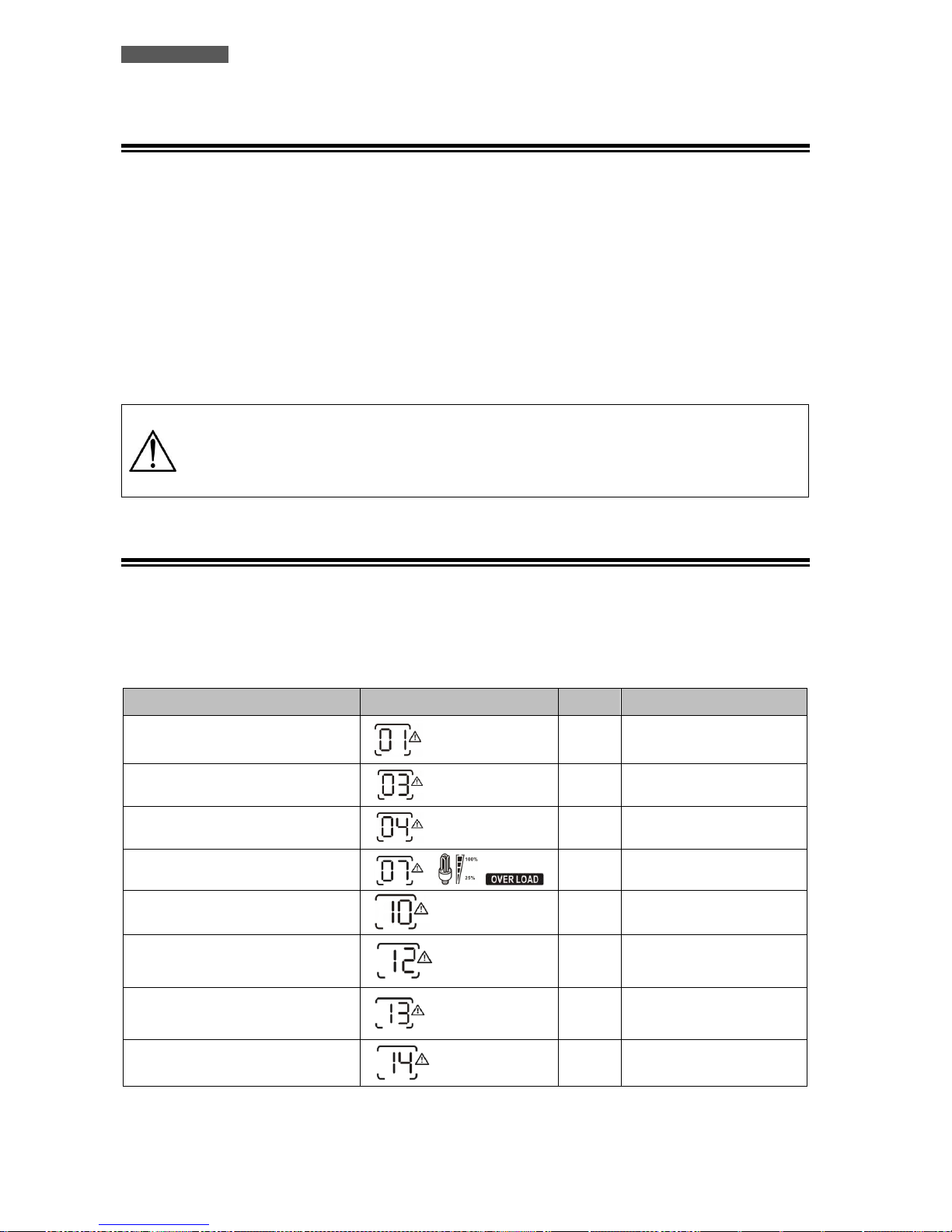
ITALIANO
Manuale utente 76 ATA Energy Storage System MM
9.3 Controllo del Carico
L’ATA indica il livello del carico in Uscita per mezzo del display grafico, visualizzandolo, come descritto nel
capitolo 5.
Quando il carico in Uscita supera il valore nominale l’ATA segnala la condizione di Overload (Sovraccarico) per
mezzo del display grafico e dell’allarme acustico, come descritto nella “Tabella Allarmi” e nel capitolo
“Anomalie ed Interventi”.
L’ATA segnala un Overload minore del 110% con allarme acustico.
L’ATA ha la capacità di sopportare un Overload compreso tra il 110% e il 150% per 10 secondi e tra il 150% e 200%
per 5 secondi. Se la condizione di Overload permane ATA commuta automaticamente in modalità Bypass.
Se la condizione di Overload scompare, ATA commuta automaticamente dal modo Bypass al modo di
funzionamento SBU.
Controllare che l'ATA non indichi mai la condizione di Overload.
Non applicare all'ATA un carico maggiore del valore nominale di targa (vedere le
specifiche di POTENZA del capitolo “Caratteristiche Tecniche”), in quanto può
esserne danneggiato. In tal caso vengono a decadere le condizioni di garanzia.
9.4 Segnalazioni di Allarme
La condizione di Allarme è segnalata dall’emissione dell’allarme acustico. I tipi di Allarme che si possono
verificare durante il normale funzionamento sono elencati nella “Tabella Allarmi” sotto riportata. Per ogni
allarme è indicato anche il simbolo che lampeggia sul display grafico.
Per maggiori dettagli consultare il capitolo “Anomalie ed Interventi”.
TIPO DI ALLARME
SIMBOLO (lampeggiante)
CODICE
ALLARME ACUSTICO
La ventola è bloccata quando
l’inverter è attivo
01
Allarme acustico tre volte
ogni secondo
Tensione batterie troppo alta
03
Allarme acustico una volta
ogni secondo
Tensione batterie bassa
04
Allarme acustico una volta
ogni secondo
Sovraccarico
07
Allarme acustico una volta
ogni 0,5 secondi
Potenza in uscita richiesta bassa
10
Doppio allarme acustico
ogni 3 secondi
Arresto ricarica da pannelli solari a
causa della tensione batterie troppo
bassa
12
Arresto ricarica da pannelli solari a
causa della tensione dei pannelli PV
troppo alta
13
Blocco ricarica da pannelli solari a
causa di un sovraccarico
14
Tabella Allarmi
Page 83
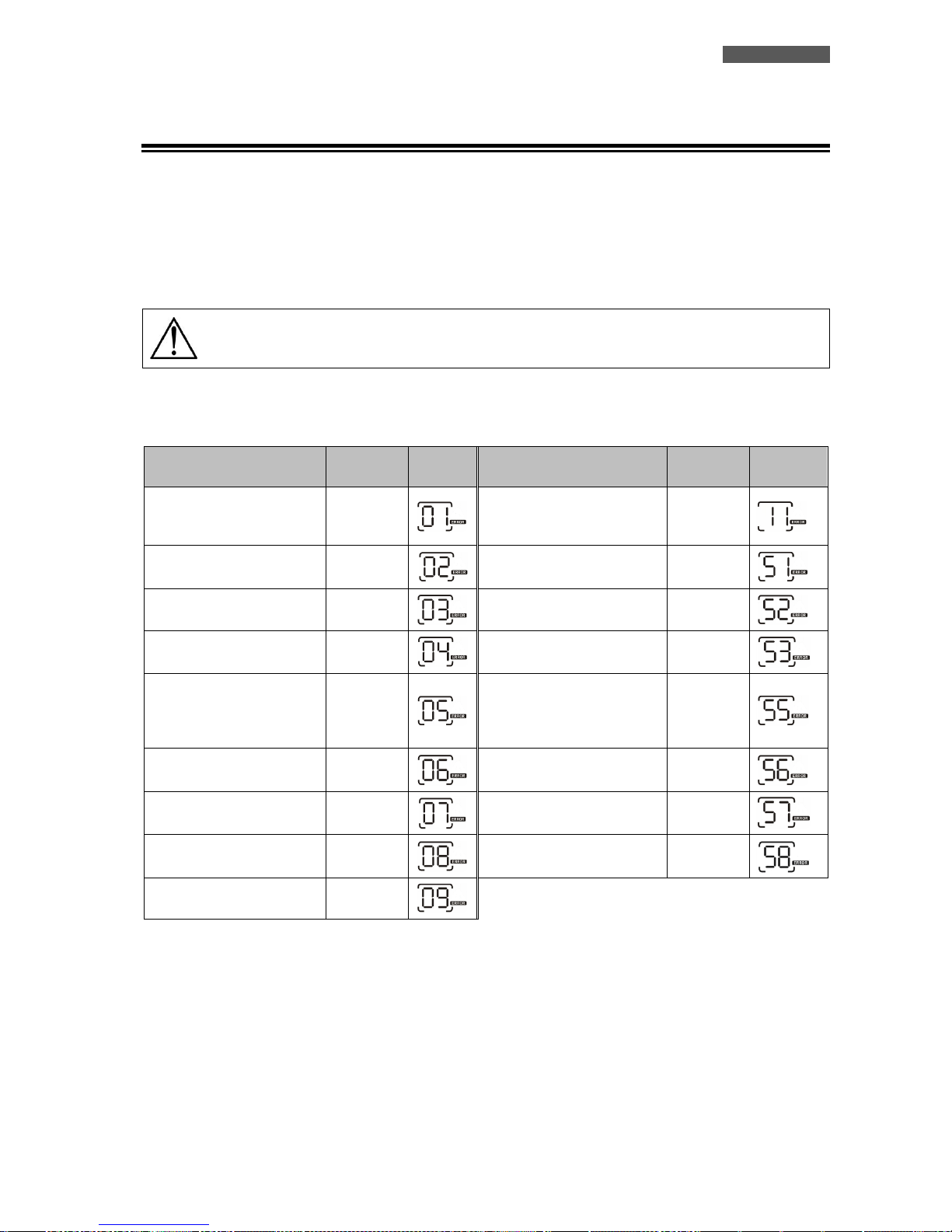
ITALIANO
ATA Energy Storage System MM 77 Manuale utente
9.5 Segnalazioni di Guasto
Se durante il funzionamento si verifica un Guasto (Fault), allora l’ATA segnala la condizione critica con
l’emissione dell’allarme acustico continuo. Inoltre sul display grafico è visualizzato il codice di Fault. Per
maggiori dettagli consultare il capitolo “Anomalie ed Interventi”.
In caso di Fault, prego controllare i carichi alimentati, i collegamenti, la ventilazione, i pannelli PV, la linea
elettrica d’Ingresso, le batterie. In ogni caso non provare mai a riaccendere l’ATA senza aver trovato la causa del
guasto. Se il problema non può essere risolto, contattare immediatamente il Servizio Assistenza.
Solo in caso d’emergenza: per evitare ulteriori rischi o danni disconnettere l’ATA dalla
linea d’Ingresso, da box batterie esterni, dai pannelli PV e dalle linee d’Uscita.
Di seguito è riportata la “Tabella Fault”, con elencati tutti i tipi di Fault possibili, e per ognuno è indicato il
codice Fault e il simbolo visualizzati sul display grafico.
TIPO DI GUASTO (FAULT)
CODICE
SIMBOL
O
TIPO DI GUASTO (FAULT)
CODICE
SIMBOLO
La ventola è bloccata
quando l’inverter non è
attivo.
01
Errore commutazione rete
11
Temperatura alta
02
Sovra corrente o tensione
51
Tensione batterie alta
03
Vdc Bus bassa
52
Tensione batterie bassa
04
Errore soft start inverter
53
Cortocircuito uscita o
rilevamento
sovratemperatura di un
componente interno.
05
Tensione DC alta su uscita
AC
55
Tensione uscita alta
06
Circuito batterie aperto
56
Overload prolungato
07
Errore sensore di corrente
57
Vdc Bus alta
08
Tensione d’uscita troppo
bassa
58
Errore Bus soft start
09
Tabella Guasti
Page 84
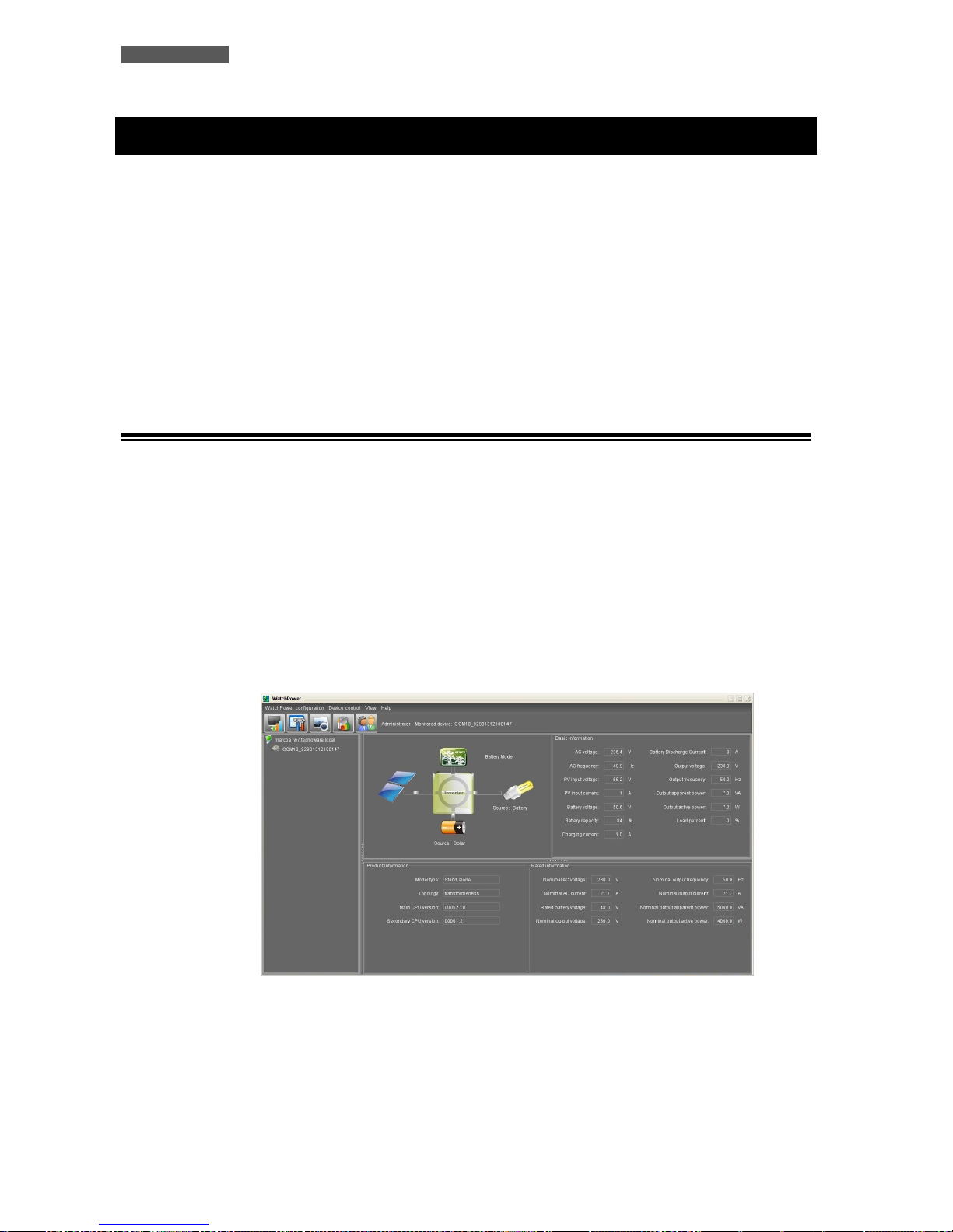
ITALIANO
Manuale utente 78 ATA Energy Storage System MM
10 Interfacce di Comunicazione
L’ATA è dotato delle Interfacce RJ45/RS232 e USB, utilizzabili come porte di comunicazione con un Personal
Computer.
Le Interfacce di Comunicazione RJ45/RS232 e USB non possono essere attive contemporaneamente. Per attivare
la comunicazione RJ45/RS232 è sufficiente collegare solo il cavo RJ45/RS232; per attivare la comunicazione USB
è sufficiente collegare solo il cavo USB.
I segnali delle Interfacce RJ45/RS232 e USB sono tutti isolati tramite foto-accoppiatori dalle tensioni
pericolose presenti all’interno dell’ATA.
Collegandosi al sito internet www.tecnoware.com, è possibile scaricare gratuitamente la versione aggiornata del
software di gestione dell’ATA, WatchPower, compatibile con i più diffusi Sistemi Operativi.
È possibile aggiungere un’Interfaccia RS485 opzionale.
10.1 WatchPower
Il software di gestione WatchPower permette di monitorare il funzionamento del sistema, visualizzarne i valori
(corrente da pannelli fotovoltaici, corrente da batterie, capacità delle batterie, potenza collegata in uscita,
frequenza di lavoro ed altro), impostare i parametri di funzionamento dell’ATA, registrazione dei dati generati
dal sistema, visualizzare su rappresentazione grafica l’andamento nel tempo dei dati registrati dall’ATA ed
estrapolare questi dati su foglio di lavoro Excel. Inoltre è possibile impostare la segnalazione tramite mail delle
eventuali anomalie riscontrate dal sistema.
Per poter cambiare le impostazioni del sistema è necessario eseguire l’accesso come amministratore. La
password di default è “administrator”. E’ possibile cambiare la password, dopo aver effettuato il primo accesso
con la password di default.
10.1.1 Monitoraggio funzionamento sistema e visualizzazione valori elettrici
Dalla schermata sopra riportata, è possibile visualizzare i valori di funzionamento del sistema. Il
diagramma indica quali parti del sistema sono attive.
I valori di funzionamento del sistema vengono visualizzati in tempo reale ed indicano la tensione e
frequenza d’ingresso, la tensione e la corrente generata dai pannelli fotovoltaici, la tensione, capacità,
corrente di ricarica e di scarica (quando forniscono energia per alimentare il carico) delle batterie, la
tensione e frequenza d’uscita e le informazioni relative all’assorbimento dei dispositivi collegati (potenza
attiva e apparente e suo valore percentuale).
Page 85
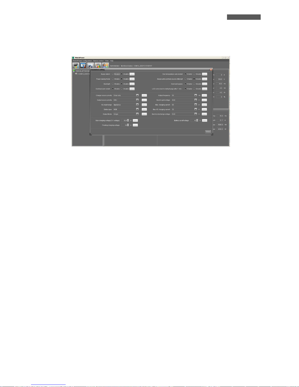
ITALIANO
ATA Energy Storage System MM 79 Manuale utente
10.1.2 Impostazione parametri di funzionamento dell’ATA
Cliccando sull’icona “Parameters Setting” (impostazione parametri), è possibile selezionare le stesse
impostazioni selezionabili direttamente a bordo macchina tramite il pannello frontale. Queste
impostazioni determinano il funzionamento dell’intero sistema. E’ possibile attivare o disattivare allarmi e
funzioni (allarme acustico, allarme in mancanza della rete di alimentazione elettrica, modalità risparmio
energia, retroilluminazione schermo, riavvio in caso di sovraccarico e/o bypass ed ecc…), modalità di
funzionamento (SBU “impostato di default”, Utility ed ecc…), priorità di alimentazione del carico (solo da
pannelli fotovoltaici, solo da rete, ibrido tra rete e pannelli fotovoltaici), parametri di funzionamento del
circuito batterie (tensione massima di ricarica, corrente di ricarica, tensione di mantenimento, valore di
tensione per raggiungimento soglia capacità di scorta, tensione minima di lavoro per la quale poi il sistema
alimenta il cario tramite rete) e eventuale configurazione in modalità parallelo o trifase.
Per applicare eventuali modifiche è necessario effettuare l’accesso come amministratore. Si consiglia di
far effettuare tali modifiche ad un personale specializzato.
Page 86
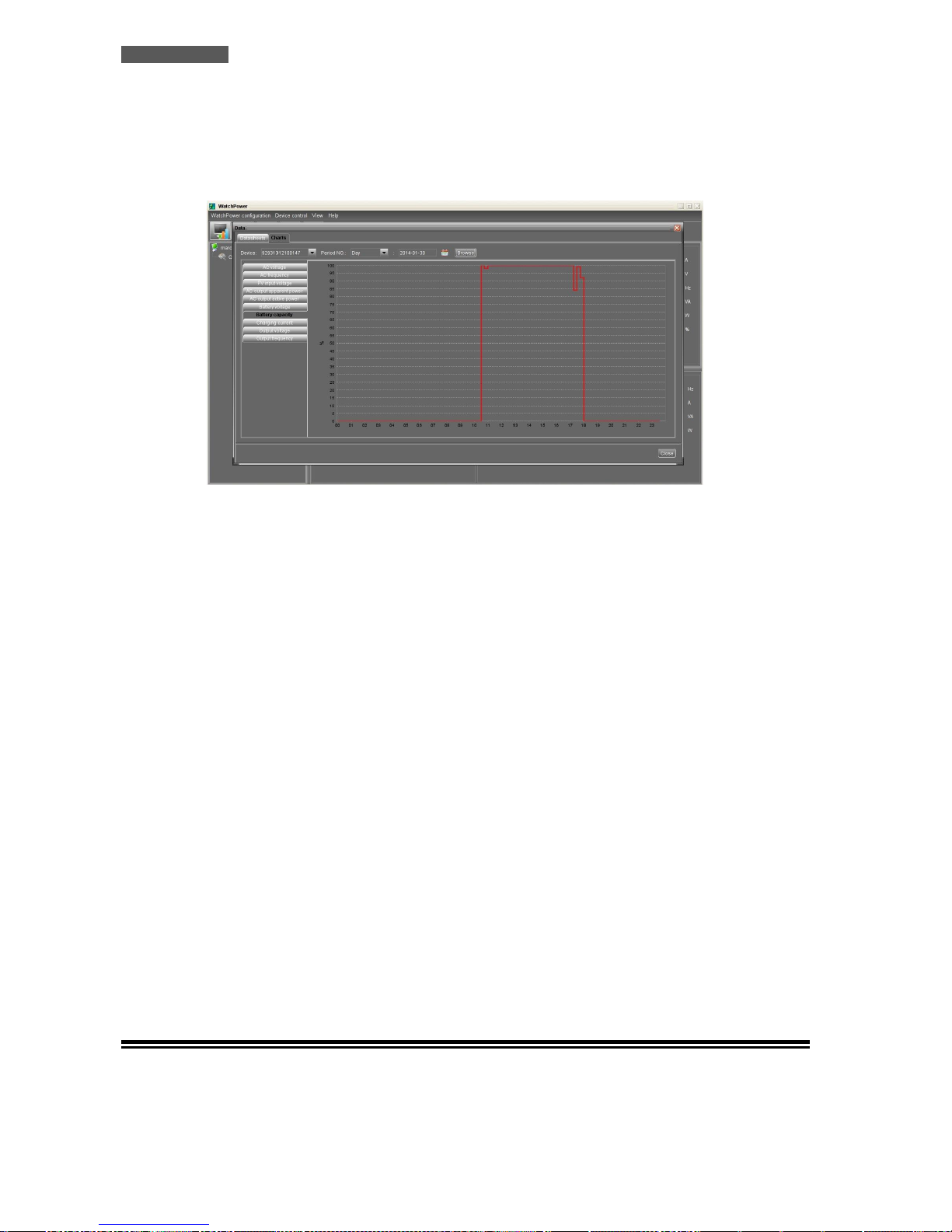
ITALIANO
Manuale utente 80 ATA Energy Storage System MM
10.1.3 Registrazione e rappresentazione grafica dei valori di funzionamento del
sistema
ATA dispone di un sistema di memorizzazione dello storico dei valori di funzionamento. E’ possibile
visualizzare questi valori graficamente o estrapolarli su foglio excel. Si accede allo storico cliccando sul
pulsante “Data”.
Nella rappresentazione grafica è possibile selezionare il tipo di parametro da visualizzare andando a
effettuare un filtraggio sull’intervallo di tempo a cui siamo interessati. Questo filtraggio può essere fatto
per ora, giorno, mese e anno.
Lo stesso tipo di filtraggio (per ora, giorno, mese e anno) può essere effettuato per i dati da estrapolare su
foglio excel.
10.1.4 Altre funzioni
Il programma permette di utilizzare altre funzioni come l’invio via mail, il cambio della password di
default, l’impostazione dei tempi di aggiornamento e memorizzazione dei valori di funzionamento del
sistema, e la selezione, la storicizzazione e l’estrapolazione su foglio excel delle anomalie di
funzionamento.
Accedendo al menù “WatchPower Configuration” è possibile impostare l’invio di messaggi tramite mail,
configurando il server di posta da utilizzare, i destinatari mail e gli eventi che scaturiscono l’invio della
mail.
Cliccando sull’icona “Event Log” si accede alla schermata che permette il filtraggio (per ora, giorno, mese
e anno) delle anomalie riscontrate durante il funzionamento del sistema con la possibilità di visualizzarli
o estrapolarli su foglio excel.
Cliccando sull’icona “Basic” si accede alla schermata che permette di impostare i tempi di aggiornamento
dei valori in tempo reali prodotti dal sistema, intervallo di registrazione di tali valori e il formato della
data che viene visualizzata.
10.2 Interfaccia RS485
È possibile utilizzare un’Interfaccia RS485 per rendere compatibile ATA con un sistema di comunicazione
compatibile alla RS485. L’Interfaccia RS485 è opzionale.
Page 87
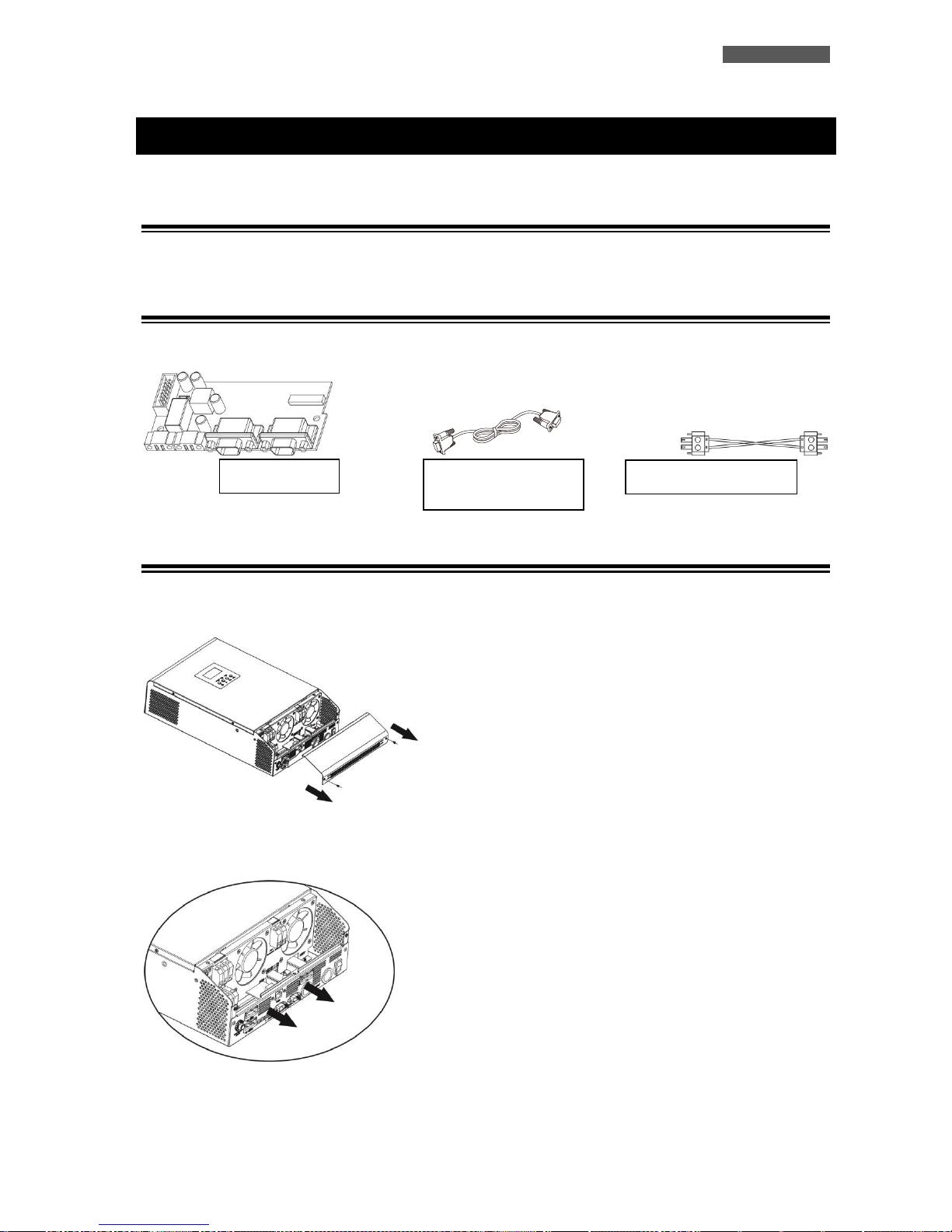
ITALIANO
ATA Energy Storage System MM 81 Manuale utente
11 Modalità Connessione Parallelo
11.1 Introduzione
E’ possibile porre in parallelo fino a 4 unità e la massima potenza supportabile è di 20KVA/16KW (per ATA 5.0 MM).
11.2 Contenuto Confezione del Kit Parallelo
Sotto riportato il contenuto della confezione:
11.3 Installazione Kit Parallelo
1. Rimuovere il pannello metallico, come riportato nella figura sottostante.
2. Rimuovere la scheda comunicazioni (scheda con porta RJ45 e USB).
Scheda
Cavo comunicazione
parallelo
Cavo corrente di sharing
Page 88
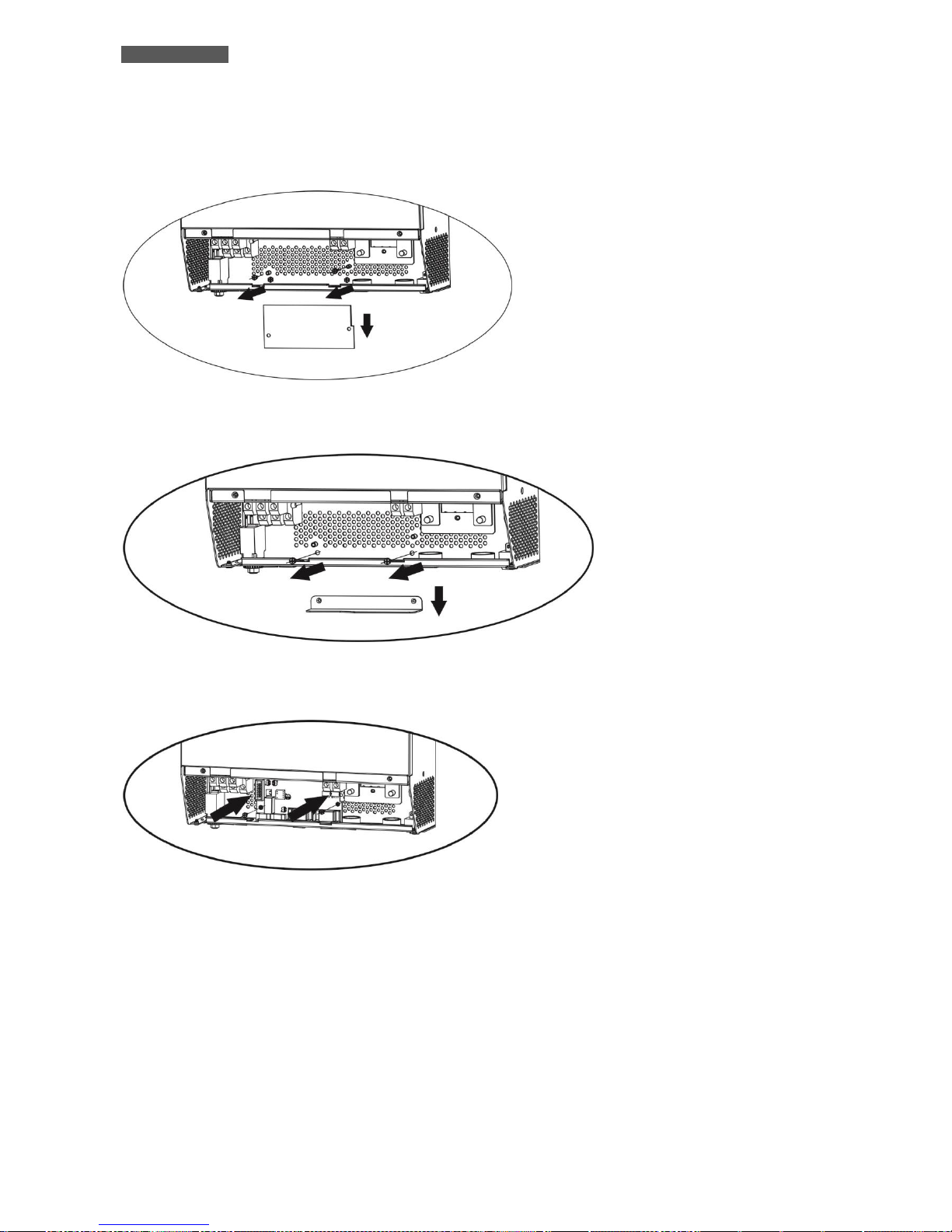
ITALIANO
Manuale utente 82 ATA Energy Storage System MM
3. Rimuovere le viti come riportato nell’immagine sottostante e in seguito rimuovere il flat a 2 e 14 pin e la
scheda posta sotto quella comunicazione.
4. Rimuovere il coperchio metallico come riportato nella figura sottostante.
5. Installare la scheda parallelo.
Page 89
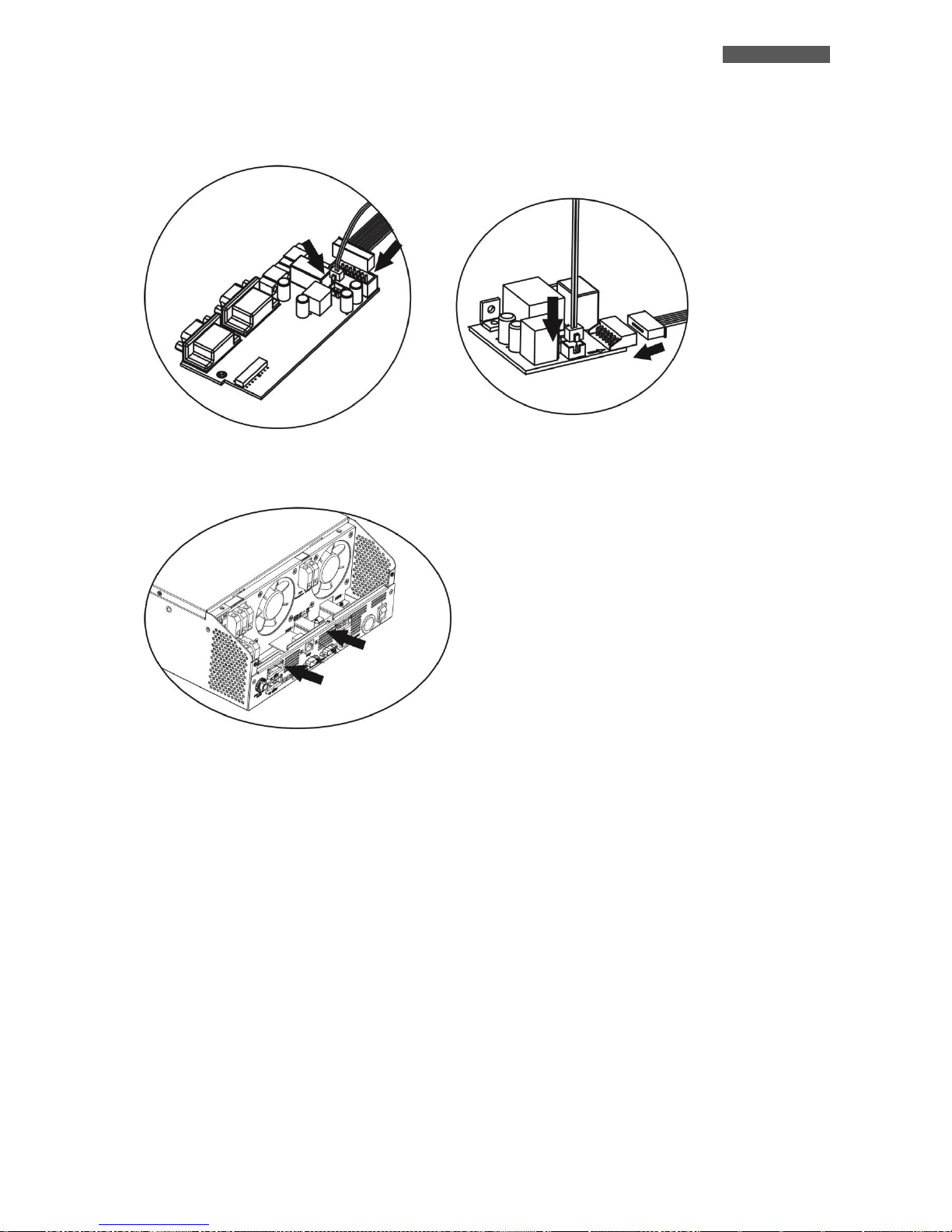
ITALIANO
ATA Energy Storage System MM 83 Manuale utente
6. Riconnettere i flat a 2 e 14 pin sulla scheda parallelo e comunicazioni. Vedi immagini sottostanti.
7. Installare nuovamente la scheda comunicazioni dove era stata rimossa in precedenza.
8. Rimontare il coperchio metallico rimosso al punto 1.
Scheda Parallelo
Scheda Comunicazioni
Page 90
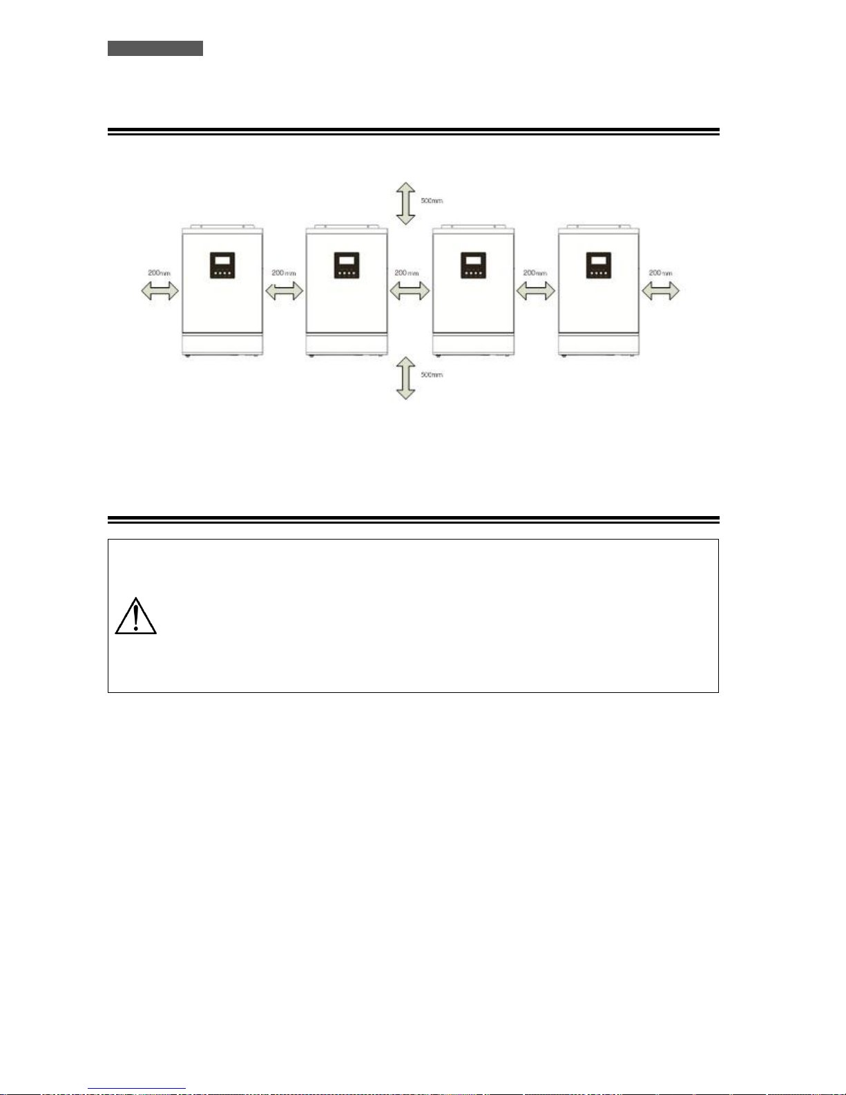
ITALIANO
Manuale utente 84 ATA Energy Storage System MM
11.4 Installazione Unità
Riferirsi all’immagine sottostante quando si installano più unità.
NOTA: Per favorire l’areazione per diminuire la dissipazione di calore prodotta dalle unità ATA, è opportuno
installare quest’ultime lasciando 20 cm di spazio fra le unità e 50 cm di spazio al di sopra e al di sotto di ciascuna
unità. Porre attenzione ad installare le unità alla stessa altezza.
11.5 Connessione Batterie
ATTENZIONE! La tipologia di batterie impostata su ogni ATA deve essere identica, altrimenti il
sistema va in errore.
ATTENZIONE: la lunghezza dei cavi di connessione dalle batterie alle unità ATA deve essere circa
la stessa. Altrimenti la differenza di tensione che potrebbe venirsi a creare fra ciascun ATA e le
batterie, potrebbe causare il non funzionamento del sistema.
ATTENZIONE: E’ opportuno installare un sistema di protezione tra ciascun ATA e il circuito
batterie.
Riferirsi al diagramma sotto riportato per la connessione delle batterie.
Page 91
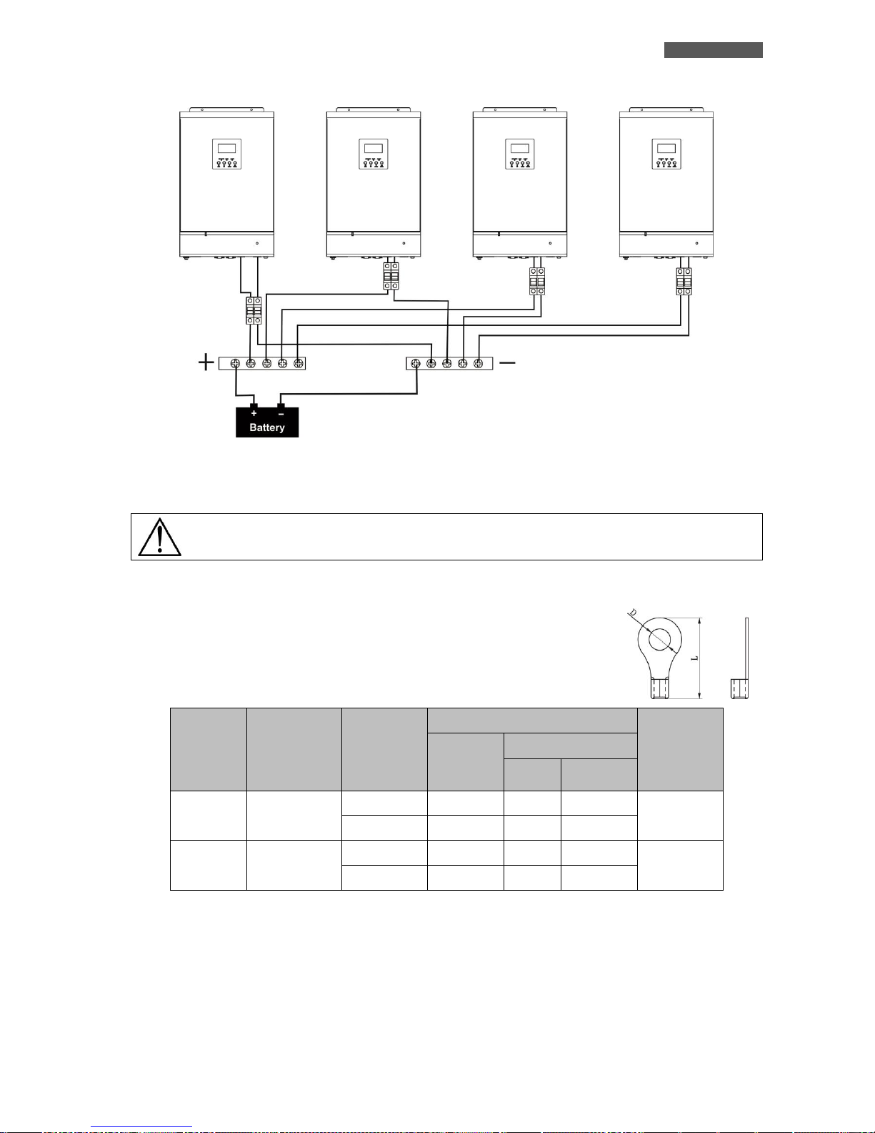
ITALIANO
ATA Energy Storage System MM 85 Manuale utente
Il sistema di batterie può essere realizzato anche con dei paralleli di batterie.
ATTENZIONE! Il pacco batterie deve essere comune a tutti gli inverter posti in parallelo
Per il dimensionamento dei cablaggi, fare riferimento alla tabelle sottostante.
Dimensionamento cablaggi e terminali batterie:
MODELLO
ATA
AMPERAGGIO
TIPICO
DIMENSIONE
CABLAGGI
TERMINALE AD ANELLO
COPPIA DI
SERRAGGIO
DIAMETRO
CAVO
(mm2)
DIMENSIONI
D (mm)
L (mm)
4.0
67 A
1*4 AWG
22
6.4
33.2
2 ~ 3 Nm
2*8 AWG
14
6.4
29.2
5.0
84 A
1*4 AWG
22
6.4
33.2
2 ~ 3 Nm
2*8 AWG
14
6.4
29.2
Terminale:
Page 92
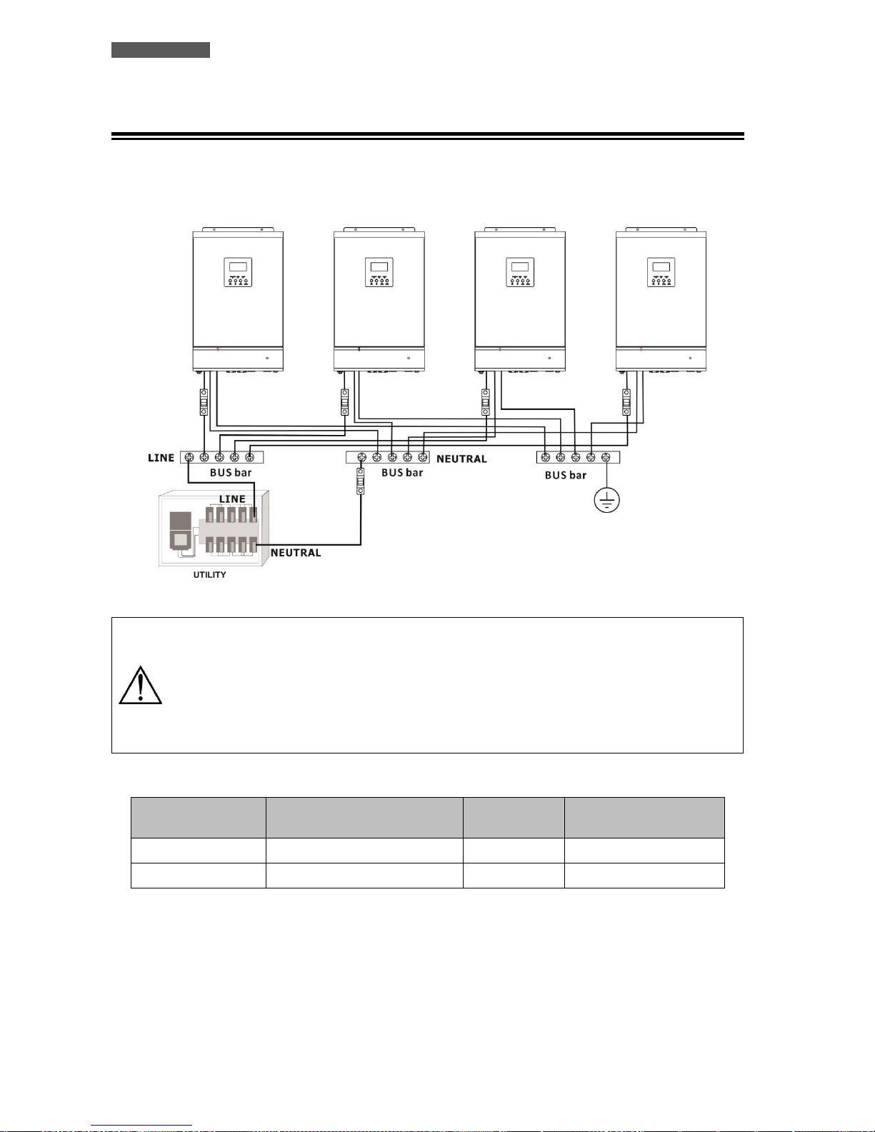
ITALIANO
Manuale utente 86 ATA Energy Storage System MM
11.6 Connessione Alimentazione d’Ingresso
Connettere la rete elettrica d’alimentazione alle barre di alimentazione delle unità ATA, suddividendo i
collegamenti di fase, neutro e terra. E’ opportuno installare dei sistemi di protezione sulla linea di fase di ogni
unità ATA e sulla linea di neutro del sistema. Fare riferimento al diagramma sottostante.
ATTENZIONE: Solo le linee di fase di ogni ATA sono da porre sotto un sistema di protezione. Non
è possibile installare dei sistemi di protezione su la linea di neutro di ogni ATA. Le linee di neutro
sono poste in comune sulla rispettiva barra di connessione. La protezione della linea di neutro
deve essere posta tra la rete di alimentazione e la barra di connessione di neutro.
ATTENZIONE: Verificare che la lunghezza di tutti i cavi di alimentazione sia il più simile possibile
per ogni unità ATA, in modo da garantire un equa distribuzione della corrente assorbita.
Fare riferimento alla tabella sottostante per il corretto dimensionamento dei cavi di collegamento.
MODELLO ATA
AMPERAGGIO INTERRUTTORE DI
PROTEZIONE
DIMENSIONI
CAVO
COPPIA DI SERRAGGIO
4.0
40 A
10 AWG
1.4 ~1.6Nm
5.0
50 A
8 AWG
1.4 ~1.6Nm
Page 93
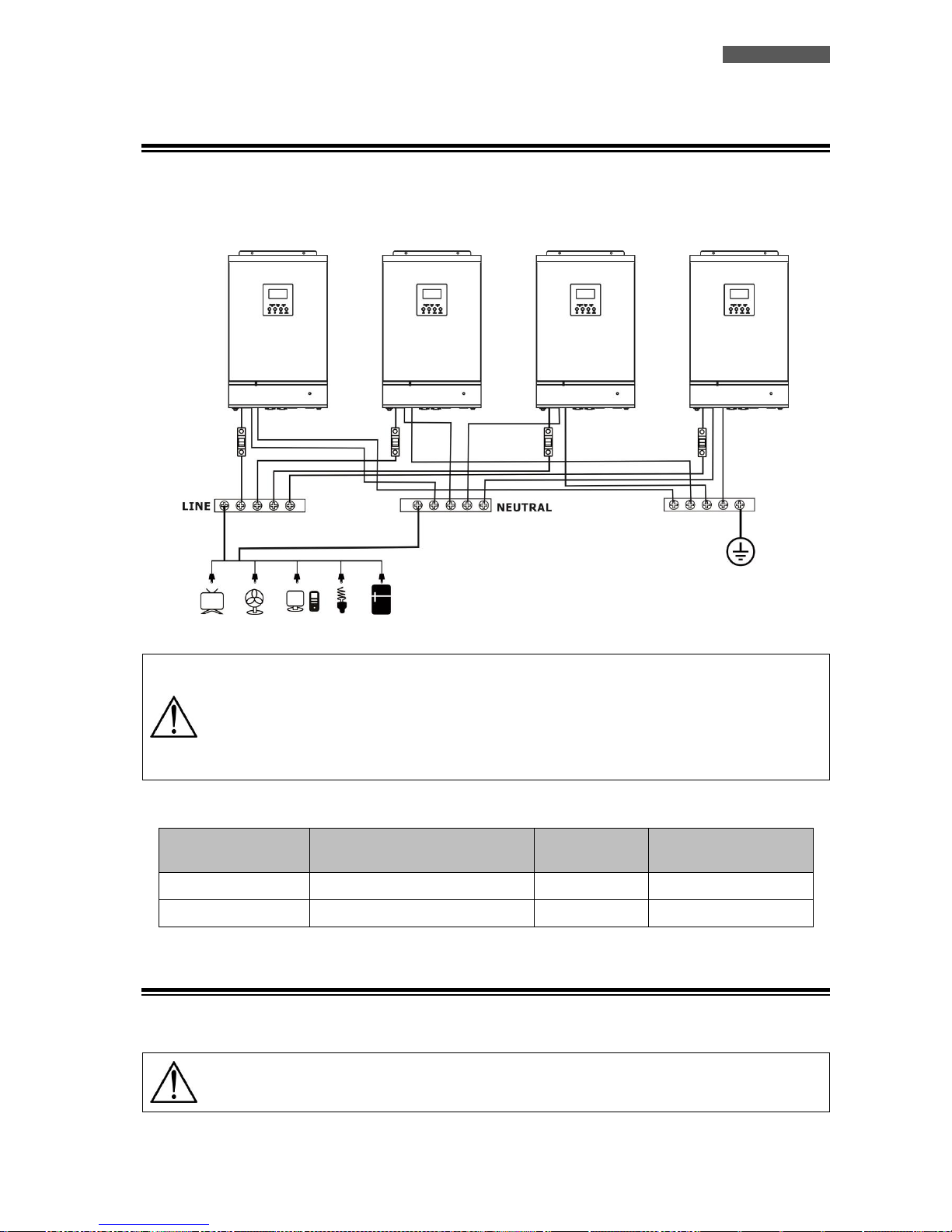
ITALIANO
ATA Energy Storage System MM 87 Manuale utente
11.7 Connessione Circuito d’Uscita e Carico
Connettere la linea di fase, neutro e di terra dell’uscita di ogni unità ATA alle rispettive barre di collegamento.
E’ opportuno installare dei sistemi di protezione sulle linee d’uscita di ogni unità ATA. Fare riferimento al
diagramma sottostante.
ATTENZIONE: Solo le linee di fase di ogni ATA sono da porre sotto un sistema di protezione. Non
è possibile installare dei sistemi di protezione su la linea di neutro di ogni ATA. Le linee di neutro
sono poste in comune sulla rispettiva barra di connessione.
ATTENZIONE: Verificare che la lunghezza di tutti i cavi di alimentazione sia il più simile possibile
per ogni unità ATA, in modo da garantire un equa distribuzione della corrente assorbita.
Fare riferimento alla tabella sottostante per il corretto dimensionamento dei cavi di collegamento.
MODELLO ATA
AMPERAGGIO INTERRUTTORE DI
PROTEZIONE
DIMENSIONI
CAVO
COPPIA DI SERRAGGIO
4.0
40 A
10 AWG
1.4~1.6Nm
5.0
50 A
8 AWG
1.4~1.6Nm
11.8 Connessione Pannelli Fotovoltaici
Fare riferimento al capitolo “Installazione” per la connessione del sistema di pannelli fotovoltaici.
ATTENZIONE: Ogni unità ATA deve essere collegata al proprio Sistema di pannelli fotovoltaici.
Non è possibile utilizzare un sistema di pannelli fotovoltaici in comune per tutte le unità ATA.
Page 94
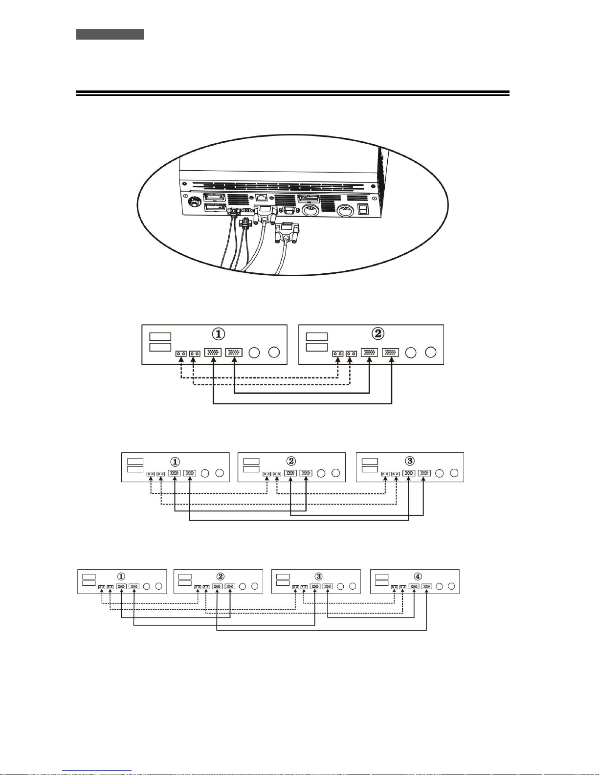
ITALIANO
Manuale utente 88 ATA Energy Storage System MM
11.9 Connessione Cavi del Kit
Fare riferimento all’immagine sottostante per la connessione dei cavi compresi nel kit parallelo.
2 unità ATA in parallelo:
3 unità ATA in parallelo:
4 unità ATA in parallelo:
Page 95
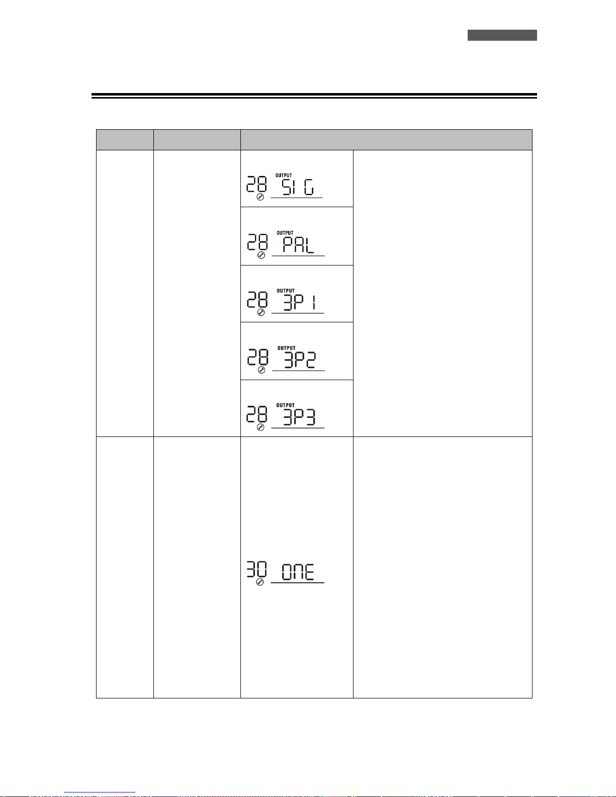
ITALIANO
ATA Energy Storage System MM 89 Manuale utente
11.10 Impostazione Parametro
Questo parametro è impostabile solo con ATA in modalità stand-by.
SETTAGGIO
DESCRIZIONE
OPZIONI SELEZIONABILI
28
Modalità Uscita:
ATA può operare in
modalità singola,
parallelo, fase S,
fase R e fase T.
Singolo:
Quando si utilizza ATA in un sistema
parallelo, è necessario impostare su “PAL”
questo settaggio.
Con questo parametro, la priorità di
alimentazione d’uscita può essere
impostata su “Utility” o “SBU”. Se attiva,
la modalità di risparmio energia viene
disabilitata.
Parallelo:
Fase L1:
Fase L2:
Fase L3:
30
Condizione Utilizzo
PV
(applicabile al solo
settaggio “Solar
first” nel
parametro 1:
Priorità
alimentazione
uscita)
1 Inverter (Default):
Quando selezionata la voce “ONE”, fin
quando un inverter è connesso ai pannelli
PV e la tensione dei pannelli PV è
accettabile, Il sistema parallelo o parallelo
trifase continua a lavorare secondo il
principio di funzionamento
dell’impostazione “solar first”.
Per esempio, due inverter sono collegati in
parallelo ed è impostata la funzione “SOL”
nel parametro “priorità alimentazione
uscita”. Se uno dei due inverter è connesso
ai pannelli PV e la tensione dei pannelli PV
è accettabile, il sistema parallelo
provvederà ad alimentare il carico dai
pannelli fotovoltaici e/o dalle batterie. Se
entrambe le fonti non sono sufficienti ad
alimentare il carico, questo verrà
alimentato dalla rete elettrica.
Page 96
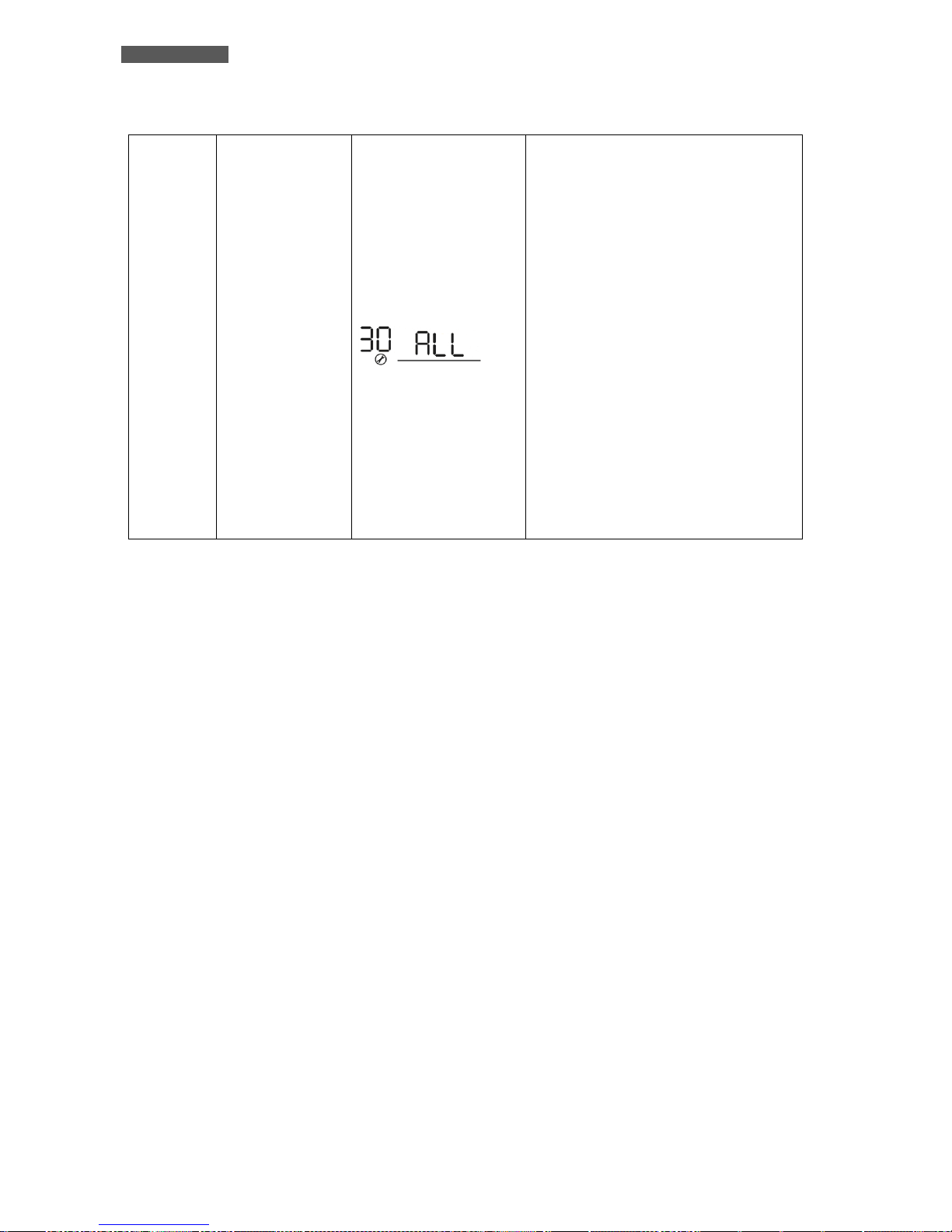
ITALIANO
Manuale utente 90 ATA Energy Storage System MM
Tutti gli Inverter:
Quando selezionata la voce “ALL”, solo
quando tutti gli inverter sono connessi ai
pannelli PV e la tensione dei pannelli PV è
accettabile, Il sistema parallelo o parallelo
trifase continua a lavorare secondo il
principio di funzionamento
dell’impostazione “solar first”.
Per esempio, due inverter sono collegati in
parallelo ed è impostata la funzione “SOL”
nel parametro “priorità alimentazione
uscita”. In questo caso, è necessario che
entrambi gli inverter siano connessi ai
pannelli PV e la tensione dei pannelli PV
sia accettabile per permettere di
alimentare il carico dai pannelli
fotovoltaici e/o dalle batterie. Altrimenti
il carico verrà alimentato dalla rete
elettrica.
Page 97
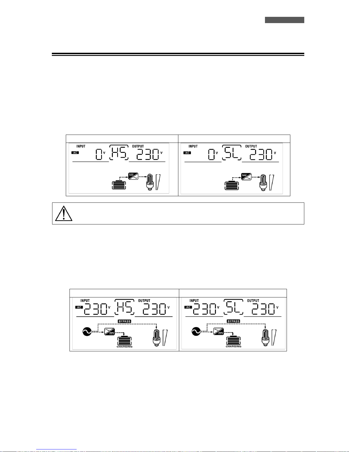
ITALIANO
ATA Energy Storage System MM 91 Manuale utente
11.11 Messa in Servizio
1. Controllare di aver rispettato le seguenti specifiche prima della messa in servizio del sistema:
Controllare le connessioni all’interno del sistema parallelo
Assicurarsi che i sistemi di protezione sulle linee di fase siano aperti e che le linee di neutro siano collegate
in comune.
2. Portare su ON gli interruttori del circuito batterie.
3. Portare su ON l’interruttore a bordo delle unità ATA.
Display LCD unità Master
Display LCD unità Slave
ATTENZIONE: Le unità Master e Slave sono selezionate casualmente.
4. Portare su ON gli interruttori dei pannelli fotovoltaici.
5. Portare su ON tutti gli interruttori a protezione della linea d’ingresso. E’ consigliato connettere tutti gli
inverter alla rete elettrica d’ingresso nello stesso momento, altrimenti verrà visualizzato in sequenza l’errore 82.
In ogni caso le unità si riavviano automaticamente, quindi quando rilevano la rete d’ingresso cominciano a
lavorare normalmente.
Display LCD unità Master
Display LCD unità Slave
6. Se non vengono visualizzati altri errori, l’installazione del sistema parallelo è completata.
7. Infine portare su ON gli interruttori dei dispositivi da alimentare. Il sistema provvederà ad alimentare questi
dispositivi.
Page 98
ITALIANO
Manuale utente 92 ATA Energy Storage System MM
ATTENZIONE: per evitare che si verifichi una condizione di sovraccarico, è opportuno avere il
sistema in funzione prima di attivare i dispositivi da alimentare a valle.
ATTENZIONE: in questo tipo di operazione ci sono dei tempi di intervento, quindi potrebbero
verificarsi delle interruzioni di funzionamento a quei dispositivi che non sono in grado di
sopportare la presenza di un tempo di intervento.
11.12 Anomalie ed Allarmi del Sistema
CODICE ERRORE
TIPO DI ERRORE (FAULT)
SOLUZIONE
60
Errore nel sistema di controllo
corrente.
1. Riavviare il sistema.
2. Se il problema persiste, contattare il Servizio
Assistenza.
71
I firmware installati su ogni unità
ATA non sono uguali.
1. Aggiornare gli inverter con lo stesso firmware.
2. Se il problema persiste, contattare il Servizio
Assistenza.
72
La corrente di uscita per ogni
inverter è differente.
1. Controllare che i cavi di sharing siano collegati
correttamente e riavviare il sistema.
2. Se il problema persiste, contattare il Servizio
Assistenza
80
Perdita dati comunicazione
2. Controllare che i cavi di comunicazioni siano
collegati correttamente e riavviare il sistema.
2. Se il problema persiste, contattare il Servizio
Assistenza
81
Perdita dati Host
82
Perdita sincronizzazione
83
La tensione batterie rilevata su ogni
unità ATA è differente.
2. Controllare che tutte le unità ATA siano
collegate correttamente alla stesso pacco
batterie.
2. Se il problema persiste, contattare il Servizio
Assistenza
84
La tensione e la frequenza
d’ingresso rilevate su ogni unità ATA
sono differenti.
2. Controllare le connessioni in ingresso e riavviare
il sistema.
2. Se il problema persiste, contattare il Servizio
Assistenza
85
Corrente di uscita sbilanciata
2. Riavviare il sistema.
2. Se il problema persiste, contattare il Servizio
Assistenza
86
Impostazione parametro di
funzionamento differente tra le
unità
2. Portare in stand-by le unità e verificare
l’impostazione del parametro 28.
2. Se il problema persiste, contattare il Servizio
Assistenza
Page 99
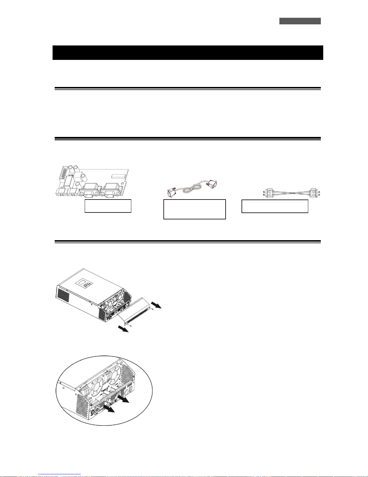
ITALIANO
ATA Energy Storage System MM 93 Manuale utente
12 Modalità Connessione Trifase
12.1 Introduzione
E’ necessario porre in parallelo 3 unità, installando un ATA per ogni fase. La massima potenza supportabile è di
15KVA/12KW (per ATA 5.0 MM).
12.2 Contenuto Confezione Kit Parallelo
Sotto riportato il contenuto della confezione:
12.3 Installazione Kit Parallelo
1. Rimuovere il pannello metallico, come riportato nella figura sottostante.
2. Rimuovere la scheda comunicazioni (scheda con porta RJ45 e USB).
Scheda
Cavo comunicazione
parallelo
Cavo corrente di sharing
Page 100
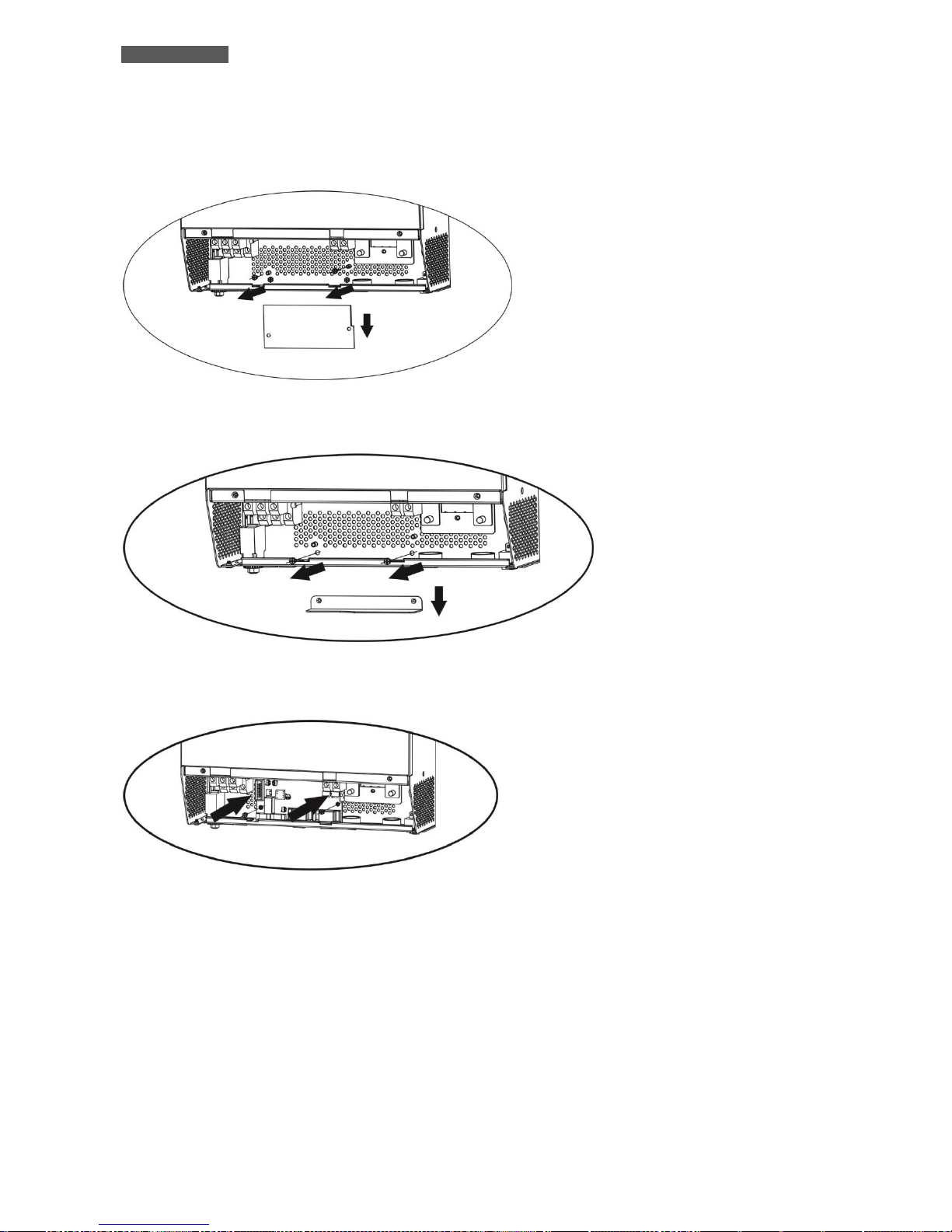
ITALIANO
Manuale utente 94 ATA Energy Storage System MM
3. Rimuovere le viti come riportato nell’immagine sottostante e in seguito rimuovere il flat a 2 e 14 pin e la
scheda posta sotto quella comunicazione.
4. Rimuovere il coperchio metallico come riportato nella figura sottostante.
5. Installare la scheda parallelo.
 Loading...