

TecnoVideo SSH204SH, SSH204, SSH204-L, SSH204SH-L, SSH204WW120 Installation Manual
...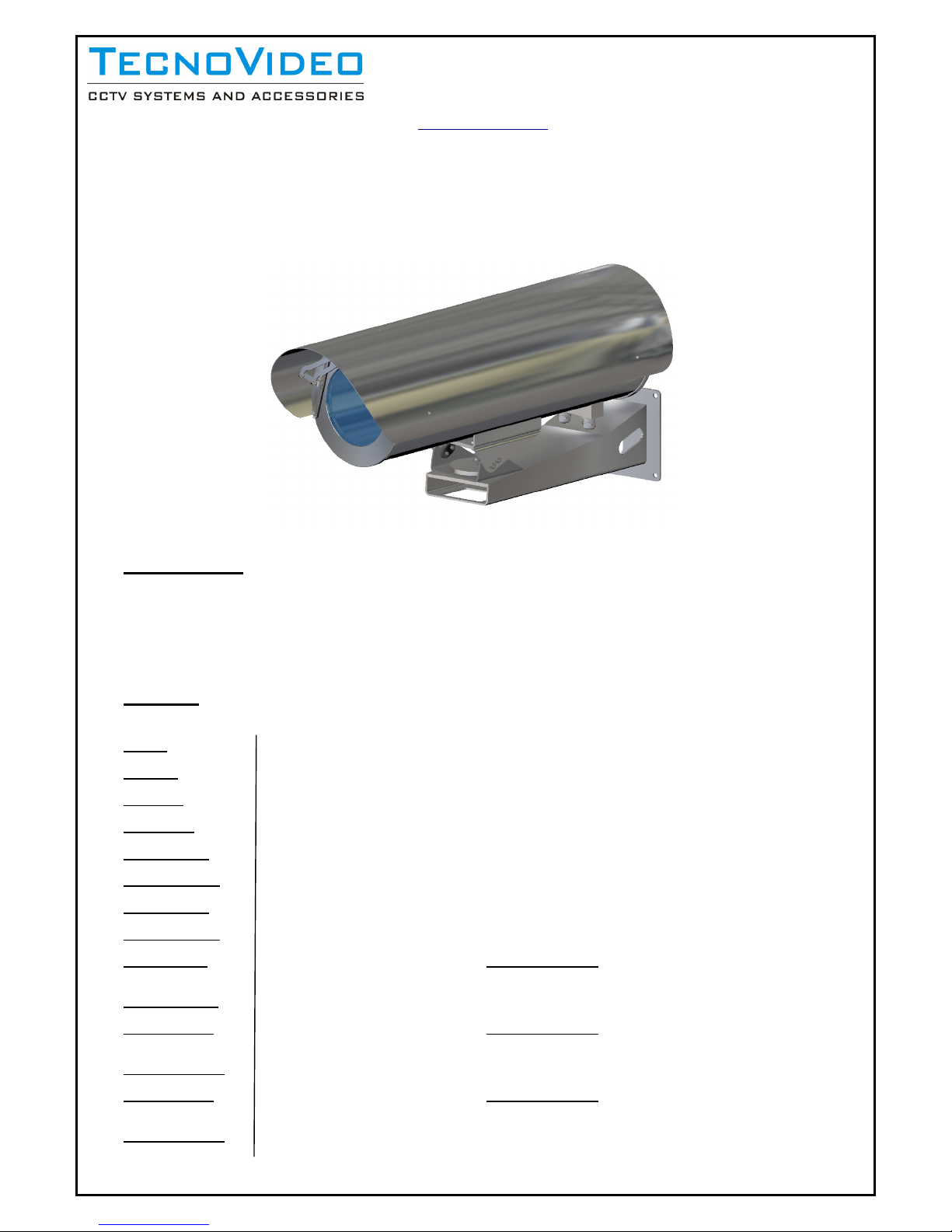
SSH204 Series
Large size Stainless Steel Camera Housing
DESCRIPTION
:
The SSH204 series is designed to protect CCTV cameras in outdoor locations, especially where corrosive environment can cause the
premature deterioration of a standard aluminium/plastic camera housing, for this purpose the SSH204 series is constructed entirely from
AISI316 stainless steel.
MODELS:
SSH204 204 mm diameter x 500 mm length. Usable front window diameters available are 70, 110, 145 mm.
SSH204-L
204 mm diameter x 600 mm length. Usable front window diameters available are 70, 110, 145 mm.
SSH204SH
Same as SSH204, plus with sunshield and thermostatically controlled heater.
SSH204SH-L
Same as SSH204-L, plus with sunshield and thermostatically controlled heater.
SSH204WW120
Same as SSH204SH, plus with wiper system. Usable front window diameter 120 mm.
SSH204WW120-L
Same as SSH204SH-L, plus with wiper system. Usable front window diameter 120 mm.
SSH204WW140
Same as SSH204SH, plus with wiper system. Usable front window diameter 140 mm.
SSH204WW140-L
Same as SSH204SH-L, plus with wiper system. Usable front window diameter 140 mm.
SSH204IRGe80
204 mm diameter x 500 mm length with Germanium window 80x3mm (usable diam. 70mm), AR/DLC
coating. Sunshield included. Heater optional.
SSH204IRGe80-L
Same as SSH204-IR-Ge80 but 600mm tube length.
SSH204IRGe120
204 mm diameter x 500 mm length with Germanium window 120x3mm (usable diam.110mm), AR/DLC
coating. Sunshield included. Heater optional.
SSH204IRGe120-L
Same as SSH204-IR-Ge120 but 600mm tube length.
SSH204IRGe155
204 mm diameter x 500 mm length with Germanium window 155x3mm (usable diam. 145mm), AR/DLC
coating. Sunshield included. Heater optional.
SSH204IRGe155-L
Same as SSH204-IR-Ge155 but 600mm tube length.
Issue 2 01/04/2008
Tecnovideo Snc
Via San L. Murialdo, 8
36030 Villaverla (VI) ITALY
Tel. +39-0445-350444
Fax. +39-0445-357259
Web: www.tecnovideocctv.com
INSTALLATION
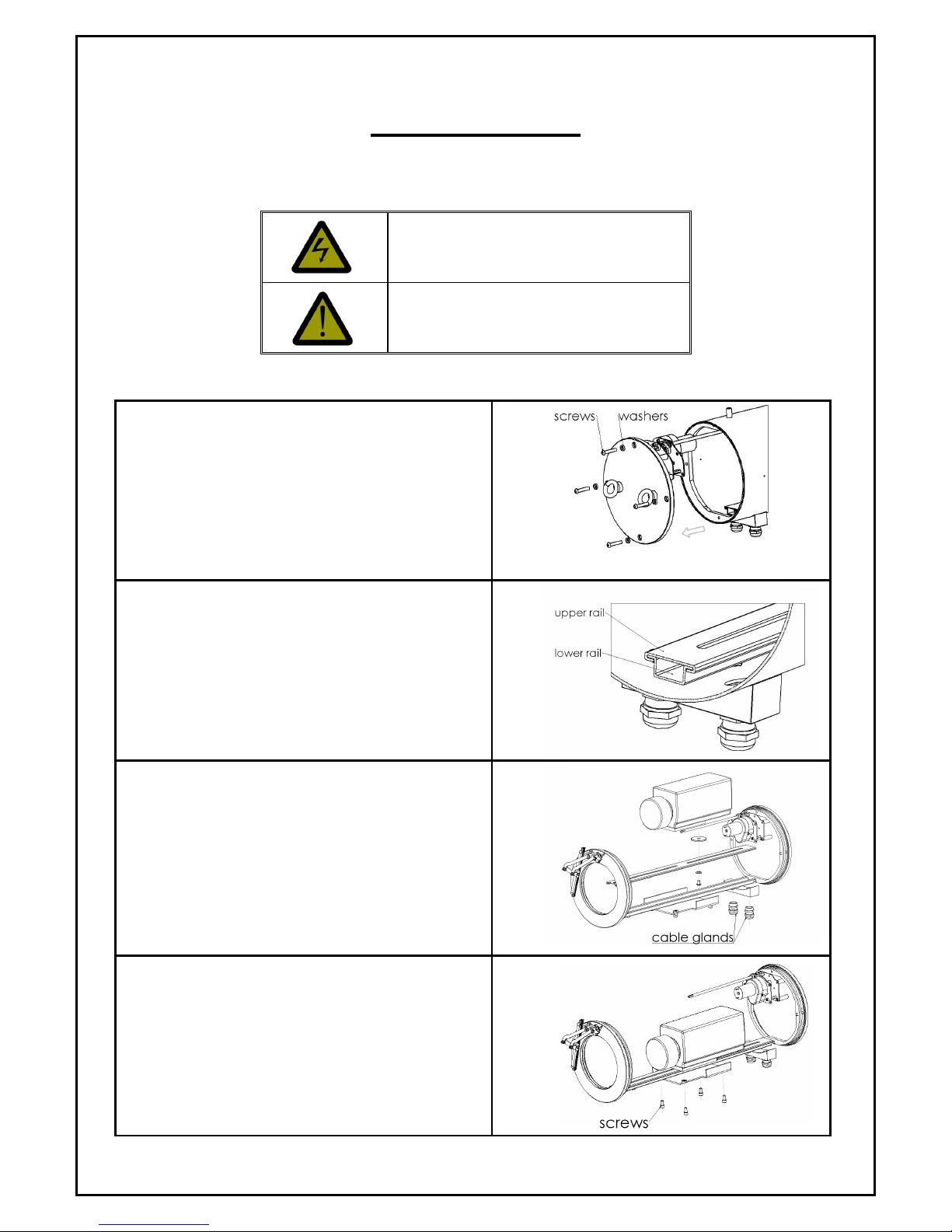
INSTALLING THE CAMERA
1. Extract the rear flange by removing the four
screws and the corresponding washers. Be
careful not to lose screws and washers.
2. Prepare the housing to install the camera,
sliding the upper rail away from the lower rail.
3. Install the camera on the upper rail using the
one of the ¼'' screws supplied, the plastic
washer and one or more spacers to be put
under the camera to adjust its height position.
Then slide the upper rail back on the lower rail
into the housing. Perform the electrical and
video connections. Cable glands are situated at
the bottom of the housing near the rear flange.
Eventually close the rear flange.
4. Use the screws at the bottom of the housing to
fasten the housing to its apposite support.
Issue 2 01/04/2008
Before performing any operation, turn off the power.
Only qualified personel can perform electrical operations
according to the regulations in force
Prior to installation and operation, read carefully this
manual of instructions
 Loading...