

TECNOvesta Smart Line Series, Smart Plus+ Series Owner's Manual
Italian Cooking Equipment
Owner Manual
Smart Line
Smart Plus+
pag. 2
SERIAL NUMBER AND ELECTRIC SPECIFICATIONS

pag. 3
INDEX
Introduction Pag. 4
General Safety Instructions Pag. 4
Unpacking Pag. 4
Installation Pag. 4
Start-up operation Pag. 11
Analog control panel operation Pag. 11
Digital control panel operation Pag. 13
How to operate a cooking cycle- bakery smart plus+ Pag. 15
How to operate a cooking cycle- gastronomy smart plus+ Pag. 13
The 10 golden operating rules Pag. 17
Quick cooking guidelines Pag. 17
Cooking tips for your recipes Pag. 17
Quick recipes table Pag. 18
Cleaning Pag. 18
Troubleshooting guide Pag. 19
Maintenance Pag. 20
Warranty Pag. 22
CE certification Pag. 23
pag. 4
INTRODUCTION
Thank you for choosing a Vesta equipment. At Tecnovesta Srl we manufacture our products utilizing only high
quality components and the latest technologies in order to guarantee the highest performance. Soon you will
realize how easy it is to prepare your dishes at their best. This appliance has been designed and produced to meet
international safety standards and by choosing the two-year extension warranty you can concentrate your
attention on your business and leave the problems to us.
Enjoy your new Vesta oven.
GENERAL SAFETY INSTRUCTIONS
This Vesta appliance has been tested and inspected to ensure the highest quality and safety standard. Read these
operating instructions carefully before you start to use the unit and save this manual and all the information (wiring
diagrams and spare parts) and instructions. This unit must be used only to cook food in catering establishments.
Any other use is therefore considered dangerous.
This manual must be read and understood by all people using or installing the equipment. If you have any questions
concerning installation, operation, or maintenance, contact Tecnovesta S.r.l. at our website www.tecnovesta.com.
NOTE: All claims for warranty must include the full model and serial number of the unit.
UNPACKING
1. Carefully remove the appliance from the pallet and box.
2. Remove all protective plastic film and packaging materials before connecting electrical power, water pipes and
drain.
3. Read all instructions in this manual carefully before initiating the installation of this appliance.
This manual is considered to be part of the appliance and is to be provided to the owner or manager of the
business or to the person responsible for training operators. Keep the manual in a place where it can be consulted
by the operator using the oven.
If you lose your manual or you need additional copies, please download it from the Tecnovesta website in
the download section at www.tecnovesta.com.
INSTALLATION
Warning: The oven must be installed by qualified professionals: electricians and plumbers. This appliance
must be branch circuit protected with proper ampere capacity, in accordance with the wiring diagram located in
this manual or the label positioned on the side of the oven. Water pipe connections must be at the right water
pressure and drainage must be safe for hot liquids. This appliance is equipped with a safety overheating thermostat
that stops power supply when temperature exceeds 340°C
Vesta convection oven must be installed in a location that will permit the oven to function for its intended
purpose. We suggest allowing adequate clearance for ventilation, proper cleaning, and maintenance. Incorrect
installation, servicing, maintenance, cleaning or modifications to the unit may result in damage, injury or death. Any
other use is not intended and is therefore considered dangerous.
pag. 5
The oven can be mounted on an optional oven stand or optional holding cabinet and leveled registering the
adjustable feet. All clearances for proper ventilation and air supply must be maintained to minimize fire hazard. Do
not locate the oven immediately adjacent to any other heat-generating appliance.
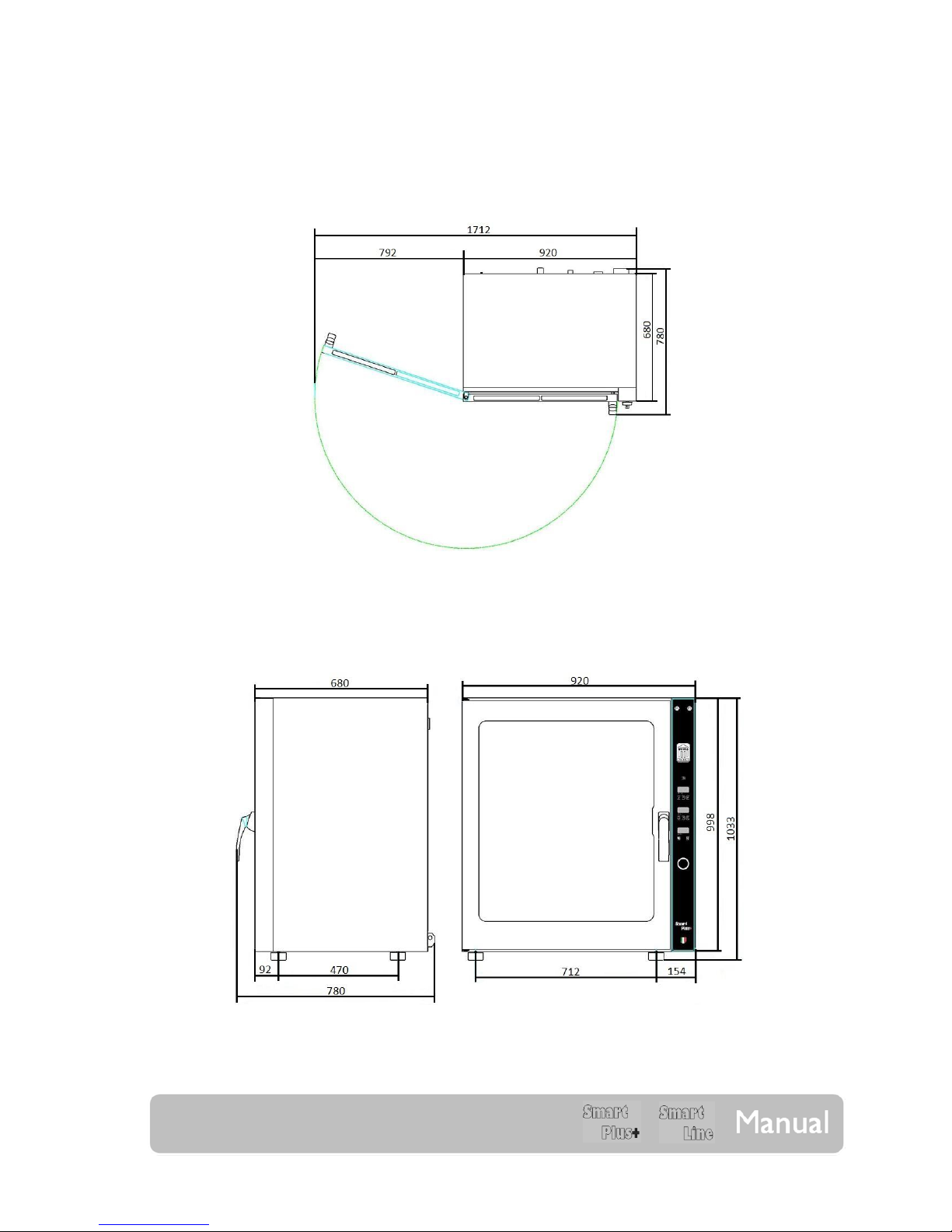
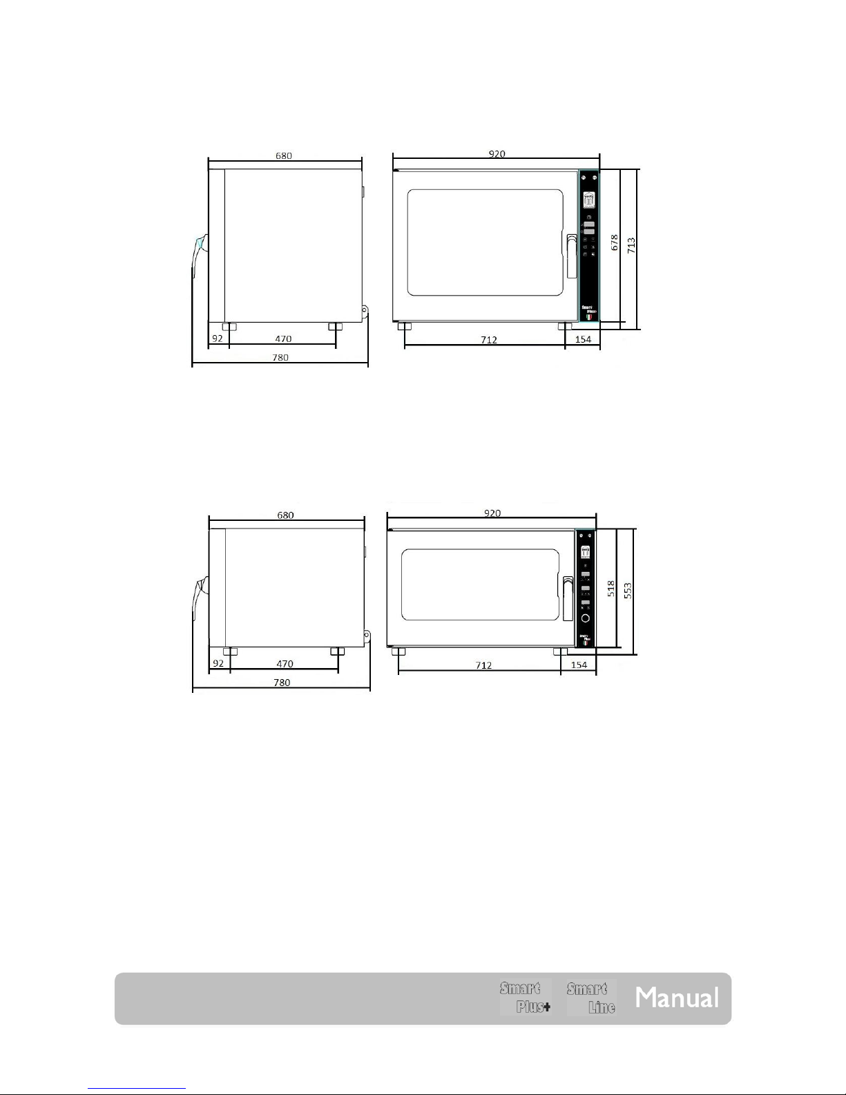
TOP VIEW – EXTERIOR DIMENSIONS (Smart Line and Smart Plus+ with lateral opening door)
FRONT AND LATERAL VIEWS – EXTERIOR DIMENSIONS (0L1064M/E; 0L1011M/E)
pag. 6
FRONT AND LATERAL VIEWS – EXTERIOR DIMENSIONS (0L0664M/E; 0L0611M/E)
FRONT AND LATERAL VIEWS – EXTERIOR DIMENSIONS (0L0464M/E; 0L0411M/E)
pag. 7
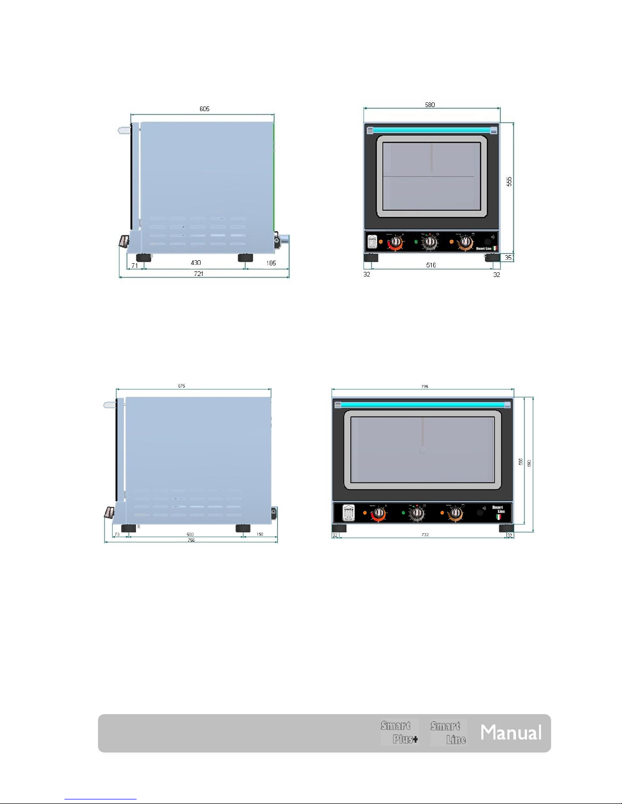
FRONT AND LATERAL VIEWS – EXTERIOR DIMENSIONS (0S0443M)
FRONT AND LATERAL VIEWS – EXTERIOR DIMENSIONS (0S0464M)
pag. 8
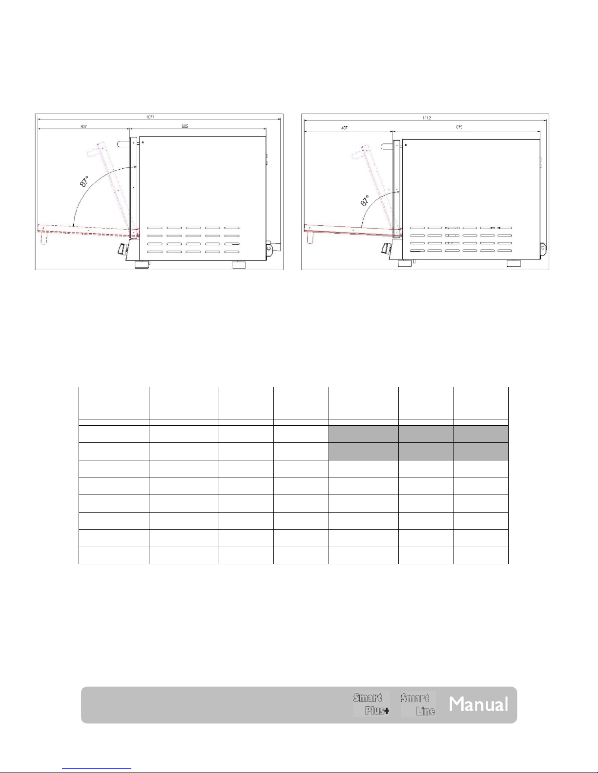
DOOR OPENING SIZES
0S0443M 0S0464M
OVEN STANDS AND HEATED CABINETS COMBINATIONS
Oven Reference Stand Reference Stand Size Levels
Heated Cabinet
Reference
Heated
Cabinet Size
Levels
0S0464M 0T0464B 795x690x940 8 – 600x400
0S0464M GN 1/1 0T0411B 795x690x940 8 – GN 1/1
0L0464M/E 0T1264 920x680x940 12 – 600x400 0C1264M 920x680x940 12 – 600x400
0L0411M/E 0T1211 920x680x940 12 – GN 1/1 0C1211M 920x680x940 12 – GN 1/1
0L0664M/E 0T1264 920x680x940 12 – 600x400 0C1264M 920x680x940 12 – 600x400
0L0611M/E 0T1211 920x680x940 12 – GN 1/1 0C1211M 920x680x940 12 – GN 1/1
0L1064M/E 0T1064 920x680x750 10 – 600x400 0C1064M 920x680x750 10 – 600x400
0L1011M/E 0T1011 920x680x750 10 – GN 1/1 0C1011M 920x680x750 10 – GN 1/1
 Loading...