

Tecnosystemi TOTAL AIR 200P EVO PLUS, TOTAL AIR 300P EVO PLUS, TOTAL AIR 300Y EVO PLUS, TOTAL AIR 200Y EVO PLUS User Manual
COD. C20002853
Sistemi
REV. 01 / 01-06-2019
MANUALE D’USO
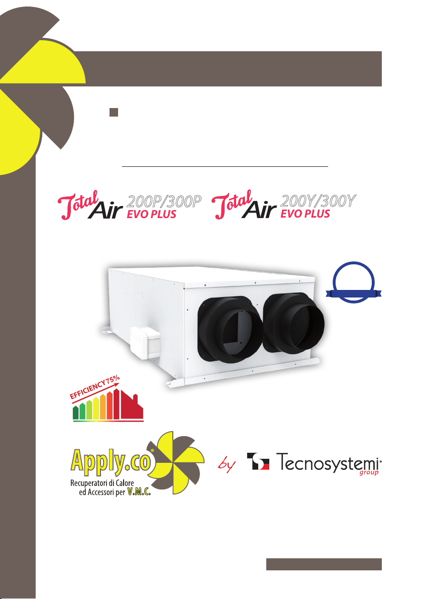
RECUPERATORE DI CALORE STATICO
CANALIZZABILE ALTA EFFICIENZA A SOFFITTO
CON BY PASS MECCANICO
12500510 - 12500530 - 12500550 - 12500570
EFFICIENCY
200P/300P
EVO PLUS
200Y/300Y
EVO PLUS
ErP
2018
READY
Tecnosystemi S.p.A.
via dell’Industria, 2/4 - Z.I. San Giacomo di Veglia
31029 Vittorio Veneto (Treviso) - Italia
Tel +39 0438.500044 - Fax +39 0438.501516
Numero Verde 800 904474 (only for Italy)
email: info@tecnosystemi.com
C.F. - P. IVA - R.I.TV IT02535780247 Cap. Soc. € 5.000.000,00 i.v.
www.tecnosystemi.com
Sistemi
INTRODUZIONE
Il sistema di Ventilazione Meccanica Controllata con recupero di calore passivo a ussi incrociati
si avvale della migliore tecnologia disponibile per quanto riguarda la componentistica e le
soluzioni costruttive,
Pensato per applicazioni interne a controsoftto, dispone di due ventilatori EC brushless.
La sezione ltrante è inglobata nella macchina e l’accessibilità all’estrazione del ltro è sul anco
laterale.
Il collegamento idraulico è caratterizzato dallo scarico della condensa dove è molto importante
prevedere un unico sifone più basso rispetto al livello della macchina.
Il funzionamento dei ventilatori consente un ricambio d’aria negli ambienti recuperando l’energia
dell’aria di ripresa prima dell’espulsione all’esterno.
In modalità Free-Cooilng, ovvero agendo sulla serranda di By-Pass, si consente all’aria esterna di
rinnovo d’entrare direttamente in ambiente lungo un percorso a bassa perdita di carico portando
il consumo di energia elettrica al minimo possibile: naturalmente questa funzione ha senso solo
se le condizioni esterne lo consentono.
REQUISITI DI SICUREZZA
REQUISITI DI SICUREZZA
Leggere il manuale dell‘ utente con attenzione prima dell’utilizzo e dell’installazione del
recuperatore di calore.
L’installazione e il funzionamento del recuperatore di calore devono essere effettuati in conformità
con il manuale dell’utente, nonché le disposizioni di normative e leggi locali e nazionali e norme
tecniche ed elettriche applicabili.
Le avvertenze contenute nel manuale dell’utente devono essere considerate attentamente in
quanto contengono informazioni vitali per la sicurezza personale.
La mancata osservanza delle norme di sicurezza può provocare lesioni o danni al recuperatore
di calore.
Leggere attentamente il manuale e tenerlo no a quando si usa il recuperatore di calore.
Quando si trasferisce il comando del recuperatore di calore, il manuale d’uso deve essere
consegnato all’operatore ricevente.
Legenda dei simboli usati nel manuale:
2
Sistemi
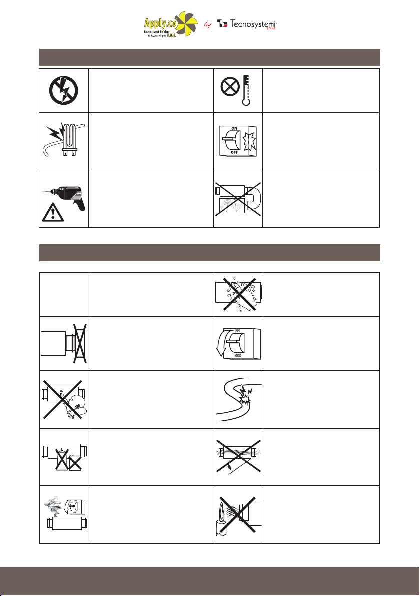
PRECAUZIONI DI MONTAGGIO
PRECAUZIONI DI MONTAGGIO
Il recuperatore di calore
deve essere scollegato dalla
rete elettrica prima di ogni
installazione o riparazione.
I
l recuperatore di calore non deve
essere utilizzato al di fuori della
gamma di temperatura indicata
nel manuale d’uso o in atmosfere
aggressive o a rischio di esplosione.
Non posizionare radiatori o
altri dispositivi in prossimità
del cavo di alimentazione del
recuperatore di calore.
Nell’installare il recuperatore
di calore, seguire le normative
di sicurezza speciche per le
apparecchiature elettriche.
PRECAUZIONI DI MONTAGGIO
PRECAUZIONI OPERATIVE DI SICUREZZA
PRECAUZIONI OPERATIVE DI SICUREZZA
Non bloccare il condotto aria
quando il recuperatore di calore
è acceso.
Impedire ai bambini di utilizzare
il recuperatore di calore.
Non utilizzare apparecchiature
o conduttori danneggiati per
collegare il recuperatore di
calore alla rete.
Usare il recuperatore di calore
solo secondo le speciche del
costruttore.
Non lavare il recuperatore di
calore con acqua. Proteggere
le parti elettriche del ventilatore
dall’ingresso di acqua.
Staccare il recuperatore di
calore dalla rete prima della
manutenzione.
Non danneggiare il cavo
di alimentazione durante
l’utilizzo del recuperatore di
calore. Non mettere oggetti
sul cavo di alimentazione.
Tenere prodotti esplosivi
ed inammabili lontano dal
recuperatore di calore.
In caso di rumori insoliti, fumo,
staccare il recuperatore di
calore dalla presa di corrente e
contattare il servizio clienti.
Non aprire il recuperatore di
calore in funzione.
Non lasciare che l’aria in
uscita dal recuperatore di
calore punti su amme aperte
o candele.
3
Sistemi
DESCRIZIONE
I recuperatori di calore Tecnosystemi nelle versioni 200-300, sono impiegati per la areazione
bilanciata di attività commerciali (negozi, ristoranti ecc.), residenziali e comunque adattabili a
tutti quegli ambienti ove sia necessario avere un ricambio d’aria, evitando nello stesso tempo la
dispersione della temperatura interna.
Il principio del recuperatore e quello di immettere in modo continuo aria fresca e pulita prelevata
dall’esterno e contemporaneamente l’aria viziata contenuta nei locali viene espulsa all’esterno
assieme a fumo odori ecc..
Quello che rende possibile questo tipo di operazione è il pacco di scambio presente all’interno
del recuperatore di calore.
Grazie alla struttura del pacco di scambio l’aria espulsa all’esterno cede il proprio calore all’aria
pulita in ingresso senza che i due ussi d’aria vengano mai in nessun modo a contatto tra di loro.
Due ltri inseriti nel recuperatore davanti alle bocche di aspirazione assicurano l’ingresso di aria
depurata da particelle e polveri.
I vantaggi di questo sistema sono molteplici, si ottiene un efcace ricambio d’aria, la temperatura
interna del locale rimane costante, l’umidità relativa viene ridotta notevolmente.
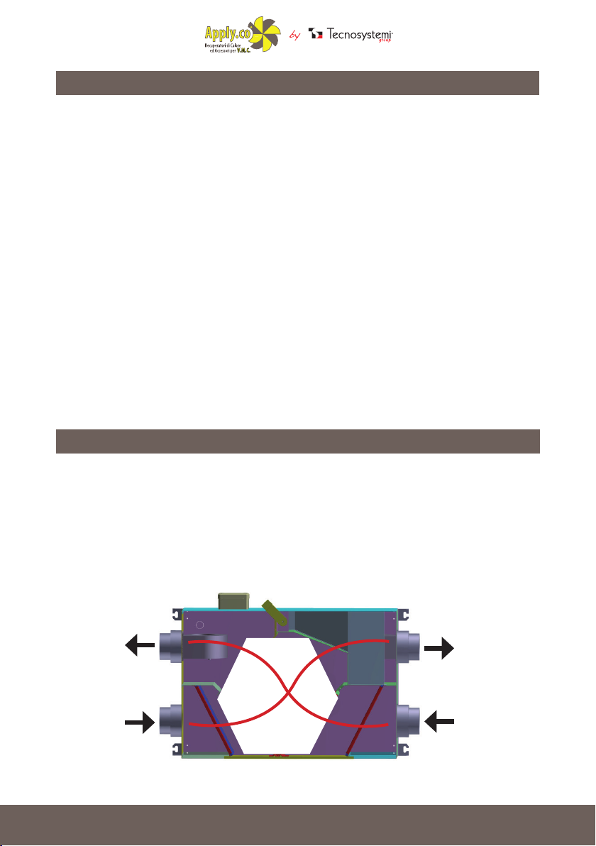
RINNOVO
Mettendo in funzione il recuperatore di calore, quando la qualità dell’aria scende sotto il livello
di comfort, viene immessa nei locali dell’ aria proveniente dall’esterno. Per ridurre il fabbisogno
energetico necessario a portare la temperatura dell’aria esterna alle condizioni volute si utilizza
un recuperatore a ussi incrociati che, sfruttando l’energia dell’aria viziata, è in grado di pretrattare
e ridurre la differenza termica dell’aria di rinnovo. Il ventilatore a basso
consumo ed alta prevalenza provvede ad espellere l’aria viziata ed energeticamente esausta
all’uscita del recuperatore di calore.
MANDATA ARIA
TR ATTATA
RIPRESA ARIA
LOCALI
4
ESPULSIONE ARIA
VIZIATA
ASPIRAZIONE
ARIA ESTERNA
Sistemi
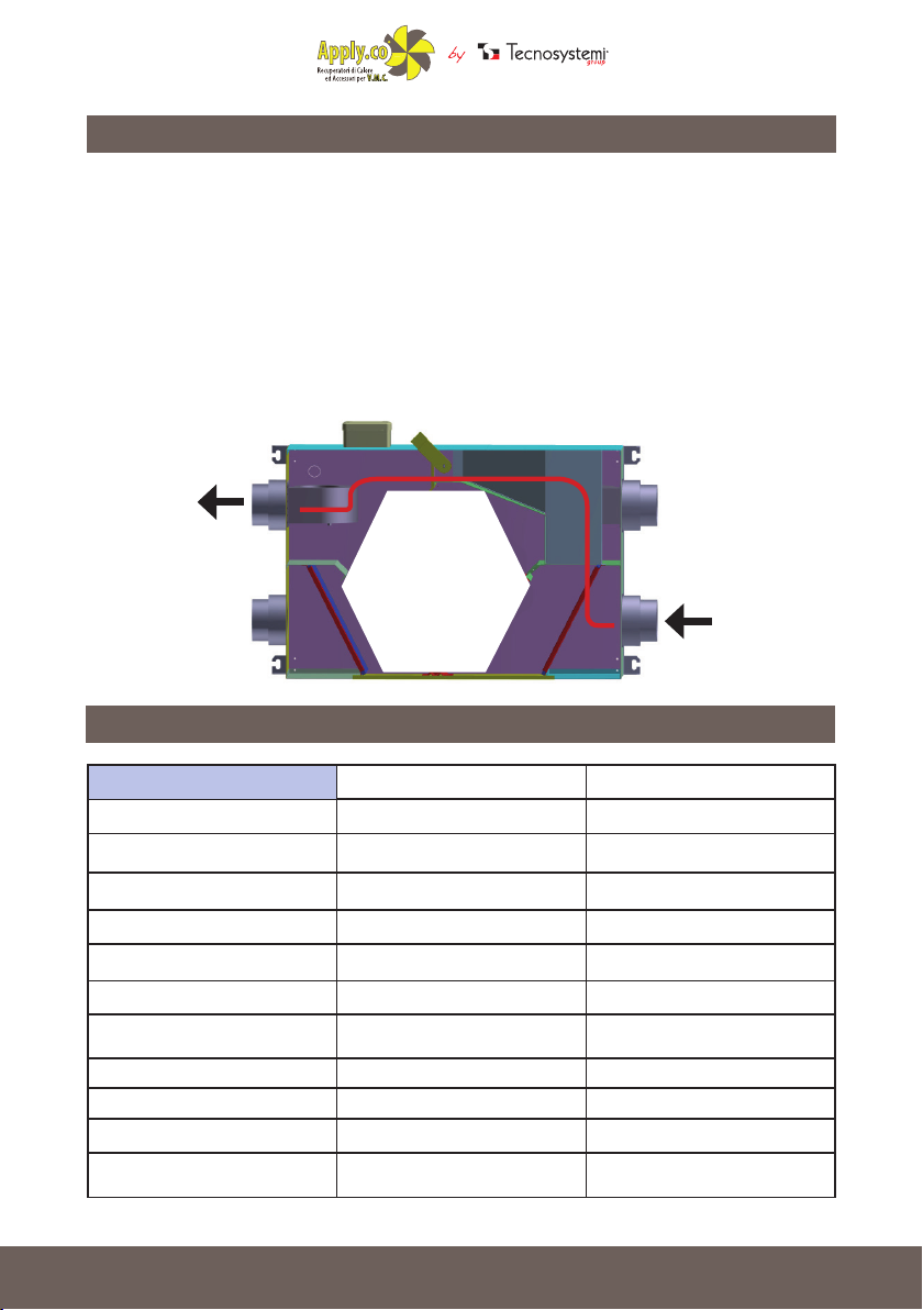
FREE - COOLING
FREE - COOLING
Quando le condizioni dell’aria esterna sono buone e cioè con una temperatura in estate più
fresca della temperatura dei locali si deve commutare manualmente la serranda di By-Pass
interna entra automaticamente in funzione ed esclude il recuperatore a ussi incrociati in modo
da non ridurre le caratteristiche confortevoli dell’aria esterna rispetto a quella interna e ridurre
i consumi di energia per la ventilazione In inverno la logica si inverte e le condizioni per cui il
Free-Cooilng viene attivato sono una temperatura dell’aria esterna superiore alla temperatura di
ripresa dell’aria viziata presente nei vari locali.
In ogni caso se la temperatura esterna si discosta troppo dal valore desiderato in ambiente,
anche se migliorativa, la modalità Free-Cooilng non avviene, quindi si ha il passaggio mitigante
attraverso lo scambiatore privilegiando sempre il comfort.
MANDATA ARIA
TR ATTATA
ASPIRAZIONE
ARIA ESTERNA
CARATTERISTICHE TECNICHE
MODELLO TOTAL AIR 200P/Y TOTAL AIR 300P/Y
VOLTAGGIO 50 Hz [V] 1 ~ 230 1 ~ 230
MASSIMA POTENZA MOTORI [W] 200 200
CORRENTE MOTORI [A] 1,94 1,94
PORTATA MASSIMA [m³/h] 200 300
RUMORE A 3 mt [dB(A)] 38 40
MATERIALE SCOCCA lamiera elettrozincata lamiera elettrozincata
COIBENTAZIONE
FILTRO: MANDATA/RIPRESA G4 G4
DIAMETRO CONDOTTI [mm] Ø 150 - 200 Ø 150 - 200
EFFICIENZA 92 % 90 %
TIPO DI RECUPERATORE a usso incrociato a usso incrociato
polietilene a celle chiuse,
10 mm
polietilene a celle chiuse,
10 mm
5
Sistemi
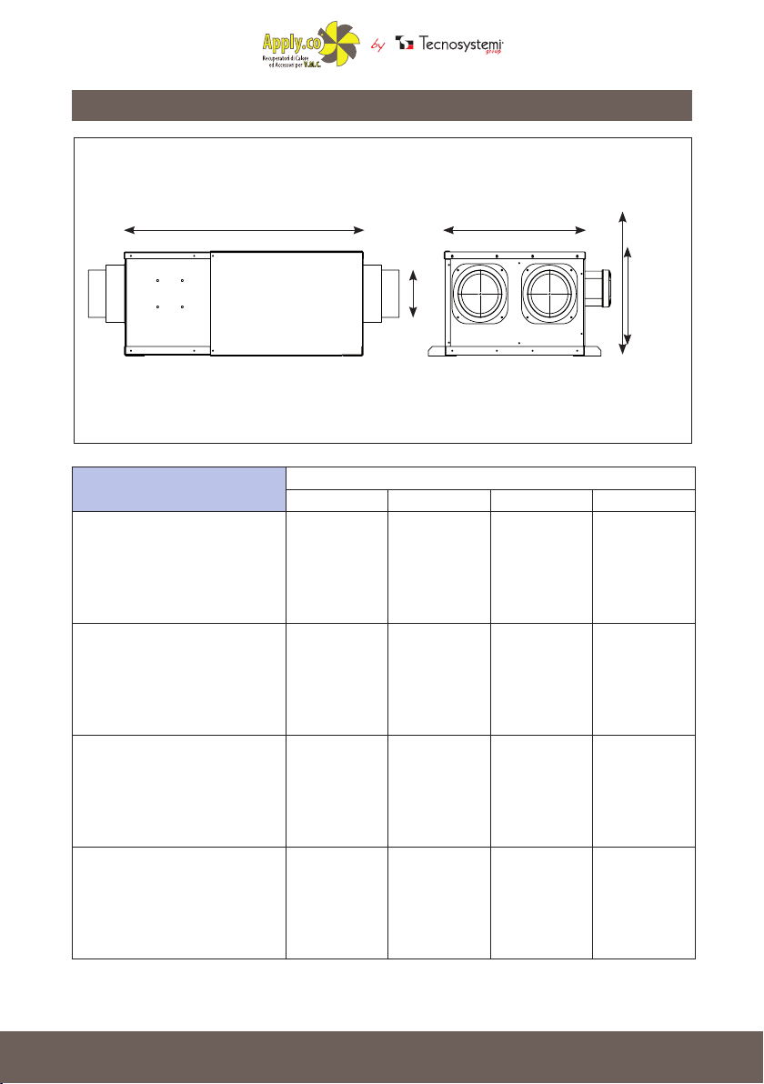
DIMENSIONI
A B
Ø
MODELLO
TOTAL AIR 200P EVO PLUS 900 500 313 150
TOTAL AIR 300P EVO PLUS 900 500 313 150
TOTAL AIR 200P EVO PLUS 900 500 313 150
A B C Ø
DIMENSIONI (mm)
C
TOTAL AIR 300P EVO PLUS 900 500 313 150
6
Sistemi
PRECAUZIONI DI MONTAGGIO
PRECAUZIONI OPERATIVE DI SICUREZZA
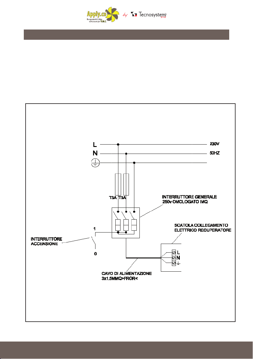
COLLEGAMENTI ELETTRICI
Il collegamento richiesto dal recuperatore è essenzialmente quello di potenza.
La potenza non è altro che l’alimentazione 230V-50Hz-1Ph.
Sulla linea di alimentazione è bene prevedere a monte sia un sezionatore sia un protettore
differenziale e magnetotermico.
COLLEGAMENTO RECUPERATORI MOD.
AIR PUR 200 - AIR PUR 300
7
Sistemi
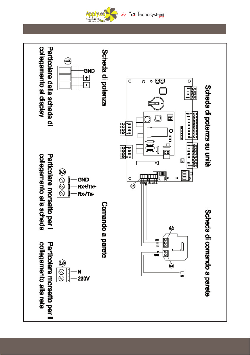
COLLEGAMENTO PANNELLO DI CONTROLLO
8
Sistemi
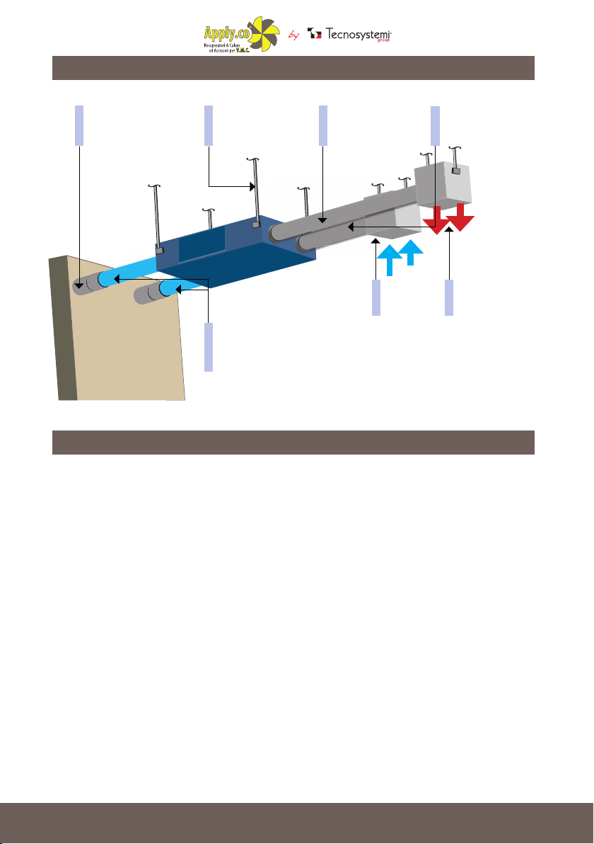
SCHEMA D’ INSTALLAZIONE RECUPERATORE
CONDOTTO
DI ASPIRAZIONE
DALL’ESTERNO
FISSAGGI
DELLA MACCHINA
A SOFFITTO
MATERIALE ISOLANTE
POSTO SU CONDOTTO
DI ESPULSIONE
ALL’ESTERNO
CONDOTTO
PASSAGGIO ARIA
DI MANDATA
RIPRESA
DELL’ARIA
CONDOTTO
PASSAGGIO
ARIA DI RIPRESA
MANDATA
DELL’ARIA
INSTALLAZIONE
La macchina nasce per installazioni a controsoftto con la possibilità di canalizzare l’aria trattata
oppure da trattare.
Tipicamente posizionata in vani tecnici o disimpegni, prediligere canalizzazioni in mandata per la
distribuzione nei vari locali dell’aria trattata.
Il ssaggio dell’apparecchiatura al solaio oppure a pavimento, avviene mediante la staffa di
ancoraggio che viene fornita con il recuperatore. La staffa è dotata di 4 estremità predisposte per
ricevere le barre lettate che ancorano la macchina. E’ responsabilità dell’installatore assicurarsi
la capacità di tenuta della supercie di ancoraggio.
Ogni macchina è dotata di 4 collarini (1 di aspirazione e 1 di espulsione su due lati), realizzati per
ricevere I condotti canalizzati dell’impianto di ventilazione.
Qualora la posizione dei tubi canalizzati sia esposta a spruzzi o getti d’acqua occorre predisporre
un’opportuna protezione per impedire di bagnare il motore elettrico interno e comprometterne
l’isolamento. L’aria pulita da immettere nell’ ambiente viene prelevata direttamente all’esterno
praticando un’apertura sul muro perimetrale della costruzione, simultaneamente l’aria viziata
proveniente dai locali interni viene espulsa all’esterno tramite una seconda apertura.
9
Sistemi
Bisogna che sia lasciato uno spazio sufciente per permettere l’apertura del pannello d’ispezione
(ltri e pacco di scambio) e alla scatola per la connessione elettrica.
I tubi canalizzati vanno ssati ai plenum del recuperatore di calore mediante fascette metalliche
che garantiscono la perfetta tenuta agli stessi.
Il cavo di alimentazione principale dev’essere collegato ad un interruttore generale, onnipolare
omologato e con distanza di apertura dei contatti > 3 mm.
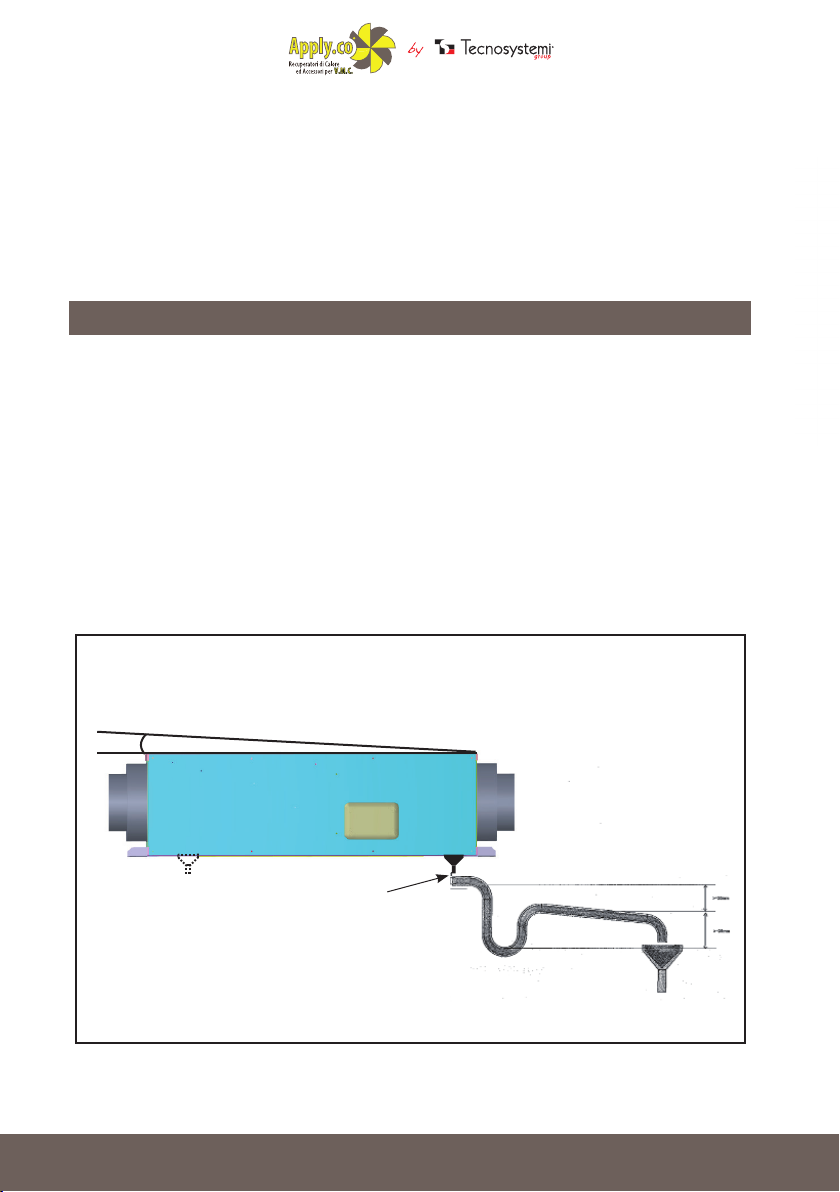
ESEMPIO IMPIANTO CONDENSA, REALIZZAZIONE E SCARICO
Durante il normale funzionamento della macchina si può avere la formazione di condensa la
quale deve uscire dal recuperatore per evitare problemi alle parti elettriche.
Per questo l’apparecchiatura è predisposta con due uscite per la condensa, e va ssata con una
pendenza del 2% verso il lato della pipetta di scarico condensa, collegandolo con un tubo per
scaricare l’acqua (attacco pipetta Ø 16 mm). (Fig.1)
Prevedere un solo sifone per lo scarico della condensa in una posizione più bassa rispetto al
fondo della macchina ed evitare percorsi senza pendenza o con tratti in salita.
Il tappo di scarico non va mai chiuso per nessun motivo.
Fig.1
10
2%
Ø 16 mm
Sistemi
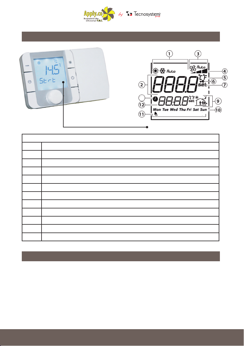
UTILIZZO DEL PANNELLO DI CONTROLLO
8
LEGENDA DISPLAY
1 MODALITÀ DI FUNZIONAMENTO
2 CAMPO PRINCIPALE
3 VELOCITÀ VENTILATORE IN MODO MANUALE / AUTOMATICO
4 INDICAZIONE VELOCITÀ VENTILATORE
5 UNITÀ DI MISURA TEMPERATURA
6 FUNZIONE BLOCCATA
7 SET POINT
8 FASCE ORARIE ATTIVE
9 FASCIA ORARIA CORRENTE
10 GIORNO DELLA SETTIMANA
11 ALLARME FILTRI SPORCHI
12 CAMPO SECONDARIO
TASTIERA
Se compare la scritta “CN” sul display signica che non c’è comunicazione con il controllo elettronico al quale è connesso. All’accensione del terminale è normale
la visualizzazione di “CN” per circa 30s, no a quando non si stabilisce la comunicazione. Nel caso
poi nella parte bassa compaia la scritta “lnit”signica che il
terminale è in fase di inizializzazione da parte del controllo master. Una permanenza in questo
stato superiore ai 10 minuti è sintomo di problemi di comunicazione.
11

Sistemi
TASTO DESCRIZIONE FUNZIONE
MODE
Selezione modalità di funzionamento: premere nchè
compare la modalità di funzionamento desiderata
Selezione velocità ventilatore: premere per selezionare la
FAN
velocità desiderata (min, med, max) o il funzionamento
automatico (Auto)
Pressione breve: abilita/disabilita le fasce orarie. L’abilitazione corrisponde all’accensione dell’icona
Pressione lunga (3 s): accesso al menu impostazione
orologio/fasce orarie. Selezionare con la manopola tra
le seguenti opzioni: CLOCK: impostazione data/ora cor-
rente: una volta selezionata l’ora lampeggerà. Ruotare
CLOCK
la manopola per selezionare e premere per confermare;
TIMEBAND: impostazione fasce orarie.
Per ogni fascia oraria (max. 6) premere per impostare l’ora di inizio e il relativo set point di temperatura. A anco
comparirà l’icona caratteristica in base allo stato
giorno/notte e alla presenza o meno dell’utente nell’abita-
zione. Selezionare ESC per uscire dalla procedura e tornare alla visualizzazione standard. ESC: per uscire
POWER
la pressione breve rappresenta l’equivalente dell’opzione
ESC.
Accensione/spegnimento della macchina. In alcuni menù
MANOPOLA
DI REGOLAZIONE
Ruotare la manopola per impostare il valore e premere
per confermare
Accesso ai menù speciali: MODE+ CLOCK per 3s per accedere al menù allarmi, attivo solo se l’
icona è accesa. Gli allarmi visualizzati dipendono dal controllo elettronico al quale è colle-
gato. Per accedere al menù parametri premere contemporaneamente i tasti FAN e POWER per 3
secondi. Impostando password diverse è possibile accedere a menù diversi.
12

Sistemi
IMPOSTAZIONE FASCE ORARIE
13

Sistemi
IMPOSTAZIONE FASCE ORARIE
14

Sistemi
IMPOSTAZIONE FASCE ORARIE
15

Sistemi
MANUTENZIONE
IMPORTANTE
Prima di eseguire qualsiasi operazione di pulizia e manutenzione, scollegare l’apparecchio
all’alimentazione mediante l’interruttore generale. (vedi schema elettrico di collegamento).
I recuperatori di calore necessitano di una manutenzione periodica (ogni 6 mesi) che si
rende necessaria al ne di ottimizzare il loro funzionamento.
L’ accesso ai ltri e al pacco di scambio, facilmente estraibili per agevolarne la pulizia,
avviene tramite il pannello di ispezione realizzato appositamente per questo scopo.
La pulizia dei ltri dev’essere effettuata con un detergente specico per ltri, il pacco di
scambio va pulito e sofato con aria compressa.
Importante! Al termine del suo utilizzo l’apparecchiatura va smaltita secondo le attuali
norme e leggi vigenti.
Le operazioni di manutenzione richieste per avere un buon funzionamento del gruppo sono la
pulizia periodica dei ltri sia dell’aria ripresa dall’ambiente sia dell’aria esterna di rinnovo: questo
intervento va eseguito ad intervalli regolari in funzione dell’ambiente in cui si trova la macchina
ma si consiglia di non superare i 30 giorni tra i vari controlli.
E’ bene controllare con cadenze annuali anche lo stato e la pulizia del recuperatore a ussi
incrociati posto al centro dell’unità e rimovibile svitando l’intero pannello laterale di tamponamento.
RIMOZIONE FILTRO
La struttura ltrante posta ad ogni ingresso ed
all’uscita dell’aria di rinnovo consente di estrarre il ltro
lateralmente.
Sequenza operativa:
• Rimuovere le viti di ssaggio (1);
• Rimuovere il pannello laterale di tamponamento (2)
dal corpo principale del recuperatore di calore;
• Slare il ltro (3) eventualmente aiutandosi con un
cacciavite.
• Eliminare polvere e residui vari utilizzando un getto
• d’aria;
• Reinserire il ltro, riposizionare il pannello di
tamponamento facendo attenzione all’allineamento
dei fori e ssare con le viti.
• Nota: Il ltro opera una barriera meccanica al
passaggio di particelle indesiderate
16
.
2
1
3

USER MANUAL
Accessories for
Air Conditioning
Air Curtains and
Accessories
Multi - Zone
Air Control System
HIGH-EFFICIENCY CEILING-MOUNTED
STATIC HEAT RECOVERY VENTILATOR
WITH MECHANICAL BY PASS
12500510 - 12500530 - 12500550 - 12500570
EFFICIENCY
200P/300P
EVO PLUS
200Y/300Y
EVO PLUS
ErP
2018
READY
Tecnosystemi S.p.A.
via dell’Industria, 2/4 - Z.I. San Giacomo di Veglia
31029 Vittorio Veneto (Treviso) - Italy
Phone +39 0438.500044 - Fax +39 0438.501516
email: info@tecnosystemi.com
C.F. - P. IVA - R.I.TV IT02535780247 Cap. Soc. € 5.000.000,00 i.v.
www.tecnosystemi.com

Accessories for
Air Conditioning
Air Curtains and
Accessories
Multi - Zone
Air Control System
INTRODUCTION
The Controlled Mechanical Ventilation system with passive cross-ow heat recovery uses the
best available technology in terms of components and construction solutions.
It was designed for indoor suspended ceiling applications and features two EC brushless fans.
The ltering section is incorporated in the machine and the lter can be removed by side access.
The hydraulic connection features a condensation discharge, which must include a single siphon
lower than the level of the machine.
Fan operation allows air change in the rooms, recovering the energy of return air before release
to the outside.
In Free-Cooling mode, namely by acting on the By-Pass damper, external fresh air is allowed to
enter directly into the environment along a path with low ow loss, bringing electricity consumption
to the minimum possible; of course, this function is suitable only if external conditions allow it.
SAFETY REQUIREMENTS
Read the User Manual carefully before using and installing the recuperator.
Installation and operation of the recuperator must be carried out in accordance with the User
Manual, as well as the provisions of local and national laws and regulations, and applicable
technical and electrical standards.
Warnings contained in the User Manual must be carefully considered as they contain vital
information for personal safety.
Failure to comply with safety regulations may result in injury or damage to the recuperator.
Read the Manual carefully and keep it for as long as the recuperator is used.
When the recuperator is transferred to another user, the User Manual must be transferred as well.
Key to symbols used in the manual:
18
WARNING
PROHIBITION

Accessories for
Air Conditioning
Air Curtains and
Accessories
Multi - Zone
Air Control System
INSTALLATION PRECAUTIONS
INSTALLATION PRECAUTIONS
The recuperator must be
disconnected from the power
supply before any installation or
repair.
Do not place radiators or other
devices near the recuperator's
power cord.
When installing the recuperator,
follow the specic safety
regulations for electrical
equipment.
INSTALLATION PRECAUTIONS
SAFETY OPERATING PRECAUTIONS
SAFETY OPERATING PRECAUTIONS
Do not block the air duct when
the recuperator is switched on.
The recuperator must not be used
outside the temperature range
recommended in the User Manual
or in aggressive or explosive
atmospheres.
Do not use damaged
equipment or conductors to
connect the recuperator to the
network.
Use the recuperator
only according to the
manufacturer's specications.
Do not wash the recuperator
with water. Protect the
electrical parts of the fan from
water.
Disconnect the recuperator
from the power supply before
maintenance.
Prevent children from using the
recuperator.
Keep explosive and ammable
products away from the
recuperator.
In case of unusual noises and/
or smoke, disconnect the
recuperator from the socket and
contact Customer Service.
Do not damage the power
cord while using the
recuperator. Do not put
objects on the power cord.
Do not open the recuperator
while in operation.
Do not let the air coming out
of the recuperator point to
open ames or candles.
19

Accessories for
Air Conditioning
Air Curtains and
Accessories
Multi - Zone
Air Control System
DESCRIPTION
The 200 and 300 versions of the Tecnosystemi recuperators are used for the balanced ventilation
of commercial (shops, restaurants, etc.) and residential settings, and adapt to those environments
in which it is necessary to exchange air, though avoid the dispersion of the internal temperature.
The principle of the recuperator is to continuously introduce fresh and clean air taken from outside
and, at the same time, expel stale air, smoke, odours, etc. from the rooms to the outside.
The exchange pack installed inside the recuperator makes this operation possible.
Thanks to the structure of the exchange pack, the air expelled outside releases its heat into inlet
clean air without the two air ows ever coming into contact with one another.
Two lters installed in the recuperator, in front of the suction vents, ensure that inlet air is free
from particles and dust.
This system has many advantages: effective air exchange, constant internal temperature and
considerable reduction of relative humidity.
RENEWAL
Air from the outside is introduced into rooms by activating the recuperator when air quality drops
below the comfort level. To reduce the energy requirement necessary to bring the outside air
temperature to the desired conditions, a cross-ow recuperator is able to pre-treat and reduce
the temperature variance of fresh air by exploiting the energy in stale air. The low-consumption
and high-pressure fan
expels stale and energetically exhausted air through the vent of the heat recovery unit.
TREATED
AIR OUTFLOW
ROOM RETURN AIR
20
EXHAUST AIR
EXPULSION
EXTERNAL AIR
ASPIRATION

Accessories for
Air Conditioning
Air Curtains and
Accessories
Multi - Zone
Air Control System
FREE - COOLING
FREE - COOLING
When outdoor air conditions are good, namely, with an indoor summer temperature that is cooler
than the outside, the internal By-Pass damper must be switched manually. It automatically enters
into operation and excludes the cross-ow recuperator, so as not to reduce the comfortable
features of outdoor air and to reduce energy consumption for ventilation In winter, the logic is
reversed and the Free-Cooling feature is activated when the outdoor air temperature is higher
than the recovery temperature of the stale air in the various rooms.
In any case, if the outside temperature deviates too much from the desired indoor temperature,
the Free-Cooling mode is not activates; therefore, the mitigating passage is carried out through
the exchanger, whose aim is to provide comfort.
TREATED
AIR OUTFLOW
EXTERNAL AIR
ASPIRATION
TECHNICAL FEATURES
CODE TOTAL AIR 200P/Y TOTAL AIR 300P/Y
VOLTAGE 50 Hz [V] 1 ~ 230 1 ~ 230
MAXIMUM MOTOR POWER [W] 200 200
MOTOR CURRENT [A] 1.94 1.94
MAXIMUM FLOW [m³/h] 200 300
NOISE at 3 meters [dB(A)] 38 40
CHASSIS MATERIAL electro-galvanized sheet electro-galvanized sheet
INSULATION
FILTERS: SUPPLY/RETURN G4 G4
DUCT DIAMETER [mm] Ø 150 - 200 Ø 150 - 200
EFFICIENCY 92 % 90 %
RECUPERATOR TYPE cross ow cross ow
closed-cell polyethylene,
10 mm
closed-cell polyethylene,
10 mm
21

Accessories for
Air Conditioning
Air Curtains and
Accessories
Multi - Zone
Air Control System
TECHNICAL FEATURES
A B
CODE
Ø
DIMENSIONS (mm)
A B C Ø
C
TOTAL AIR 200P EVO PLUS 900 500 313 150
TOTAL AIR 300P EVO PLUS 900 500 313 150
TOTAL AIR 200P EVO PLUS 900 500 313 150
TOTAL AIR 300P EVO PLUS 900 500 313 150
22

Accessories for
Air Conditioning
Air Curtains and
Accessories
Multi - Zone
Air Control System
ELECTRICAL CONNECTIONS
The recuperator must be connected to a power source.
Specically, it requires a 230V-50Hz-1Ph power supply.
It is advisable to equip the upstream of the supply line with a disconnect switch and a differential
circuit breaker.
RECUPERATOR CONNECTION MOD.
AIR PUR 200 - AIR PUR 300
switch 250 V
ignition
switch
electrical connection
box
power cord
3 x 1,5 mmq>FROR>
23

Accessories for
Air Conditioning
Air Curtains and
Accessories
Multi - Zone
Air Control System
CONTROL PANEL CONNECTION
detail of the connection board
Power board
to the display
particular clamp for connection
to the board
Power board on units
24
particular clamp for wall
connection
Wall control
Wall control board

Accessories for
Air Conditioning
Air Curtains and
Accessories
Multi - Zone
Air Control System
RECUPERATOR INSTALLATION DIAGRAM
OUTSIDE AIR
ASPIRATION
DUCT
MACHINE
CEILING
INSTALLATION
INSULATING MATERIAL INSTALLED ON THE
EXPULSION DUCT ON THE OUTSIDE
SUPPLY
AIR DELIVERY
PASSAGE
RETURN
AIR
OUTSIDE AIR
PASSAGE
OF OUTSIDE AIR
DELIVERY
AIR
INSTALLATION
The machine is designed for false ceiling installations with the possibility of channelling air treated
or to be treated.
Typically positioned in technical compartments or vestibules, it is preferable to supply pipes for
distribution in the various rooms of treated air.
The equipment is fastened to the ceiling or the oor by way of brackets supplied with the
recuperator. The bracket has 4 ends designed to receive the threaded bars that anchor the
machine. It is the responsibility of the installer to ensure that the anchoring surface is sufciently
tight.
Each machine is equipped with 4 collars (1 suction and 1 expulsion collar on both sides), designed
to receive the ducts of the ventilation system.
If the position of the ducted pipes is exposed to water splashes or jets, appropriate protection
must be provided to prevent the internal electric motor from getting wet and compromising its
insulation. Clean air to be introduced into the room is taken directly from the outside, by creating
an opening on the perimeter wall of the building; at the same time, stale air coming from the
internal rooms is expelled to the outside through a second opening.
It is necessary to leave sufcient space to open the inspection panel (lters and exchange pack)
and to access the electrical box to be connected.
25

Accessories for
Air Conditioning
Air Curtains and
Accessories
Multi - Zone
Air Control System
The ducted pipes must be xed to the plenums of the heat recovery unit by means of metal
clamps, which guarantee perfect sealing.
The main power cable must be connected to an approved, omnipolar general switch with a
contact opening distance of > 3 mm.
CONDENSATION SYSTEM SAMPLE, REALIZATION AND
DISCHARGE
During standard machine operation, condensation may form and be released from the recuperator
to avoid problems with the electrical parts.
For this reason, the appliance is set up with two condensate outlets, and must be xed with a 2%
slope towards the side of the condensation drain pipette, connecting it with a pipe to drain water
(Ø 16 mm pipette connection). (Pic. 1)
Provide only one siphon for condensate discharge in a lower position than the bottom of the
machine and avoid paths without slopes or with uphill sections.
The drain plug must never be closed for any reason.
Pic.1
26
2%
Ø 16 mm

Accessories for
Air Conditioning
Air Curtains and
Accessories
Multi - Zone
Air Control System
USE OF CONTROL PANEL
LEGEND DISPLAY
1 OPERATING MODE
2 MAIN FIELD
3 FAN SPEED IN MANUAL / AUTOMATIC MODE
4 FAN SPEED SETTING
5 TEMPERATURE MEASUREMENT UNIT
6 BLOCKED FUNCTION
7 SET POINT
8 ACTIVE TIME BANDS
9 CURRENT TIME BANDS
10 DAY OF THE WEEK
11 DIRTY FILTER ALARM
12 SECONDARY FIELD
8
KEYBOARD
If the word “CN” appears on the display, it means that there is no communication with the electronic control. When the terminal is switched on,
the “CN” display is normal for about 30 seconds, until communication is established. If he word
“Init” appears in the lower part, it means that the
terminal is being initialized by the master control. Persistence in this state for more than 10 minutes is a symptom of communication problems.
27

Accessories for
Air Conditioning
Air Curtains and
Accessories
Multi - Zone
Air Control System
KEY DESCRIPTION FUNCTION
MODE
FAN
Operating mode selection: press until the desired operating mode appears
Fan speed selection: press to select the desired speed
(min, med, max) or automatic operation (Auto)
Short press: enable/disable the time schedule. When the
icon is lit, the system is activated.
Long press (3 seconds): access to the clock /time settings
menu. Select with the knob among the following options:
CLOCK: current date/time setting: once selected, the hour
will ash. Turn the knob to select and press to conrm;
CLOCK
TIMEBAND: time band setting.
For each time slot (maximum 6), press to set the start time
and the relative temperature set point. The relevant icon
will appear next to the
day/night status and in the presence or absence of the
user in the home. Select ESC to exit the procedure and
return to the standard view. ESC: to exit.
POWER
ADJUSTMENT
KNOB
To turn machine on/off. In some menus, short press is the
equivalent of the ESC option.
Turn the knob to select and press to conrm
Access to special menus: MODE + CLOCK for 3 seconds to access the alarm menu, active only
if the icon is on. The alarms displayed depend on the electronic control to which they are
connected. To access the parameter menu, press the FAN and POWER buttons simultaneously
for 3 seconds. By setting different passwords, different menus can be accessed.
28

Accessories for
Air Conditioning
Air Curtains and
Accessories
Multi - Zone
Air Control System
TIME BAND SETTING
29

Accessories for
Air Conditioning
Air Curtains and
Accessories
Multi - Zone
Air Control System
TIME BAND SETTING
30

Accessories for
Air Conditioning
Air Curtains and
Accessories
Multi - Zone
Air Control System
TIME BAND SETTING
31

Accessories for
Air Conditioning
Air Curtains and
Accessories
Multi - Zone
Air Control System
IMPORTANT
Before carrying out any cleaning or maintenance operation, disconnect the appliance
from the power supply using the main switch. (see wiring diagram).
Heat recovery systems require periodic maintenance (every 6 months) which is necessary
in order to optimize their operation.
Access to lters and the exchange pack, which can be easily removed to facilitate cleaning,
takes place through the inspection panel designed specically for this purpose.
The lters must be cleaned with a specic lter cleaner, the exchange pack must be
cleaned and blown with compressed air.
Important! At the end of its use, the equipment must be disposed of according to current
laws and regulations in force.
Maintenance operations required to ensure the good functioning of the group include periodic
cleaning of both return air and outdoor fresh air lters; this operation must be performed at regular
intervals, depending on the environment in which the machine is installed, though we recommend
not exceeding 30 days between various checks.
It is advisable to check the status and the cleaning of the cross-ow recuperator located at the
centre of the unit, which is removable by unscrewing the entire side inll panel.
FILTER REMOVAL
The ltering structure placed at each intake and at the
fresh air outlet allows the lter to be extracted from the
side.
Operating sequence:
• Remove xing screws (1);
• Remove the side buffer panel (2) from the main
body of the heat recovery unit;
• Remove the lter (3), if necessary, with the use of a
screwdriver.
• Remove dust and various residues using
• air jet;
• Reinsert the lter, reposition the inll panel paying
attention to hole alignment and fasten screws.
• Note: The lter functions as a mechanical barrier
preventing the passage of unwanted particles.
32
2
1
3

Accessories for
Air Conditioning
Air Curtains and
Accessories
Multi - Zone
Air Control System
NOTE
33

GARANZIA / WARRANTY
Accessories for
Air Conditioning
Air Curtains and
Accessories
Multi - Zone
Air Control System
La garanzia ha durata di 2 anni a decorrere dalla data di consegna.
L’azienda fornitrice garantisce la qualità dei materiali impiegati e la corretta realizzazione dei componenti. La
garanzia copre difetti di materiale e di fabbricazione e si intende relativa alla fornitura dei pezzi in sostituzione
di qualsiasi componente che presenti difetti, senza che possa venir reclamata alcuna indennità, interesse o
richiesta di danni.
La garanzia non copre la sostituzione dei componenti che risultano danneggiati per:
• trasporto non idoneo;
• installazione non conforme a quanto specicato in questo manuale di installazione uso e manutenzione;
• la non osservanza delle speciche tecniche di prodotto;
• quant’altro non riconducibile a vizi originari del materiale o di produzione a condizione che il reclamo del
cliente sia coperto dalla garanzia e noticato nei termini e modalità richiesta dal fornitore, lo stesso si
impegnerà, a sua discrezione, a sostituire o riparare ciascun prodotto o le parti di questo che presentino
vizi o difetti.
The warranty lasts 2 years from the date of delivery.
The supplier company guarantees the quality of the materials used and the correct construction of the
components. The warranty covers defects in materials and manufacturing defects and refers to the supply of
spare parts of any components featuring defects, without any compensation, interest or claim for damages.
The warranty does not cover the replacement of components damaged due to:
• incorrect transportation;
• installation not compliant with that specied in this installation, use and maintenance manual;
• non-observance of product technical specications;
• Anything else that is not linked to original faults of the material or production provided that the
customer complaint is covered by the guarantee and a claim is made within the time limit and
in the way requested by the supplier, the same supplier will commit, at their own discretion,
to replace or repair any product or part of product showing signs of faults or defects.
SMALTIMENTO / DISPOSAL
Alla ne della sua vita utile il prodotto non deve essere smaltito insieme ai riuti urbani. Può essere
consegnato presso gli appositi centri di raccolta differenziata predisposti dalle amministrazioni
comunali, oppure presso i rivenditori che forniscono questo servizio. Per rimarcare l’obbligo di
smaltire separatamente gli elettrodomestici, sul prodotto è riportato il marchio del contenitore di
spazzatura mobile barrato.
At the end of its useful life, the product must not be disposed of with household waste. It can be
deposited at a dedicated recycling centre run by local councils, or at retailers who provide such a
service. To highlight the requirement to dispose of household electrical items separately, there is a
crossed-out waste paper basket symbol on the product.
Tecnosystemi S.p.A.
via dell’Industria, 2/4 - Z.I. San Giacomo di Veglia
31029 Vittorio Veneto (Treviso) - Italia
Tel +39 0438.500044 - Fax +39 0438.501516
Numero Verde 800 904474 (only for Italy)
email: info@tecnosystemi.com
C.F. - P. IVA - R.I.TV IT02535780247 Cap. Soc. € 5.000.000,00 i.v.
www.tecnosystemi.com
 Loading...