

Vers. 02 - 29/01/2016
USER MANUAL
HP2 30 - HP2 55 - HP2 80
WALL-INSTALLED, REVERSIBLE-FLOW VENTILATION UNIT
WITH HEAT RECOVERY AND REMOTE CONTROL
INTRODUCTION
This manual includes the technical description, operation, installation and assembly instructions,
technical data for the PICO HP2 ventilation unit with energy regeneration, referred in this document
as the "ventilation unit".
USE
The ventilation unit is designed to ensure air exchange in apartments, houses, hotels, bars and other
domestic and public buildings. The ventilation unit comes equipped with a ceramic heat exchanger
that allows air circulation due to the regeneration of energy with the heat of inowing air.
The ventilation unit is designed for mounting inside a wall. The telescopic design of the ventilation unit
allows it to be installed in walls from 300 mm to 500 mm thick.
The ventilation unit has been tested for continuous operation always connected to power mains.
The transported air must not contain ammable or explosive mixtures, chemical vapours, coarse dust,
soot and oil particles, sticky substances, brous materials, pathogenic organisms or other harmful
substances.
THE FAN IS NOT INTENDED FOR USE BY CHILDREN, PEOPLE WITH PHYSICAL OR MENTAL
DISABILITIES, THOSE WITH SENSORY DISORDERS, AND/OR ANYONE WITHOUT SUITABLE
CAPABILITY.
THE OPERATIONS OF INSTALLATION AND CONNECTION MUST BE CARRIED OUT BY
QUALIFIED PERSONNEL AFTER RECEIVING PROPER SAFETY TRAINING.
THE SITES FOR INSTALLING THE UNIT SHOULD PREVENT ACCESS TO NON-SUPERVISED
CHILDREN.
MAIN TECHNICAL PARAMETERS
The ventilation unit is designed for installation indoors with the environment temperature ranging
from -20°C to +50°C and relative humidity up to 80%.
The ventilation unit design is regularly improved and some models may be slightly dierent to the one
described in this manual
2
TROUBLESHOOTING
Issue
When switching
on the unit, its fan
does not start.
After powering
on, circuit breaker
triggers stop.
Poor air ow
The motor is blocked, the impeller is
Excess voltage from electrical short-circuit.
Possible causes
Power supply.
clogged.
Speed set to "slow".
Dirty lter, fan or exchanger.
Fault management
Check that the unit is correctly connected
to the mains, and make any adjustments
necessary.
Turn o the unit. Solving the engine block
and fan clogging. Clean the blades. Restart
the unit.
Switch o the unit. Contact customer
service.
Set to higher speed.
Clean or replace the lter, clean the fan
and regenerator. For regenerator and lter
maintenance, see page 18.
SAFETY REQUIREMENTS
Read the user's manual carefully before using and installing the single-chamber reversible-ow
ventilation unit with energy recovery, referred to below as "ventilation unit" or "unit".
The installation and operation of this unit must be carried out in accordance with the user's manual,
and the provisions of applicable local and national laws and applicable technical and electrical
standards. The warnings in the user manual must be considered carefully as they contain information
that is vital for personal safety.
Failure to follow the safety instructions can cause injury or damage to the ventilation unit.
Read the manual carefully and keep it for as long as you use the ventilation unit.
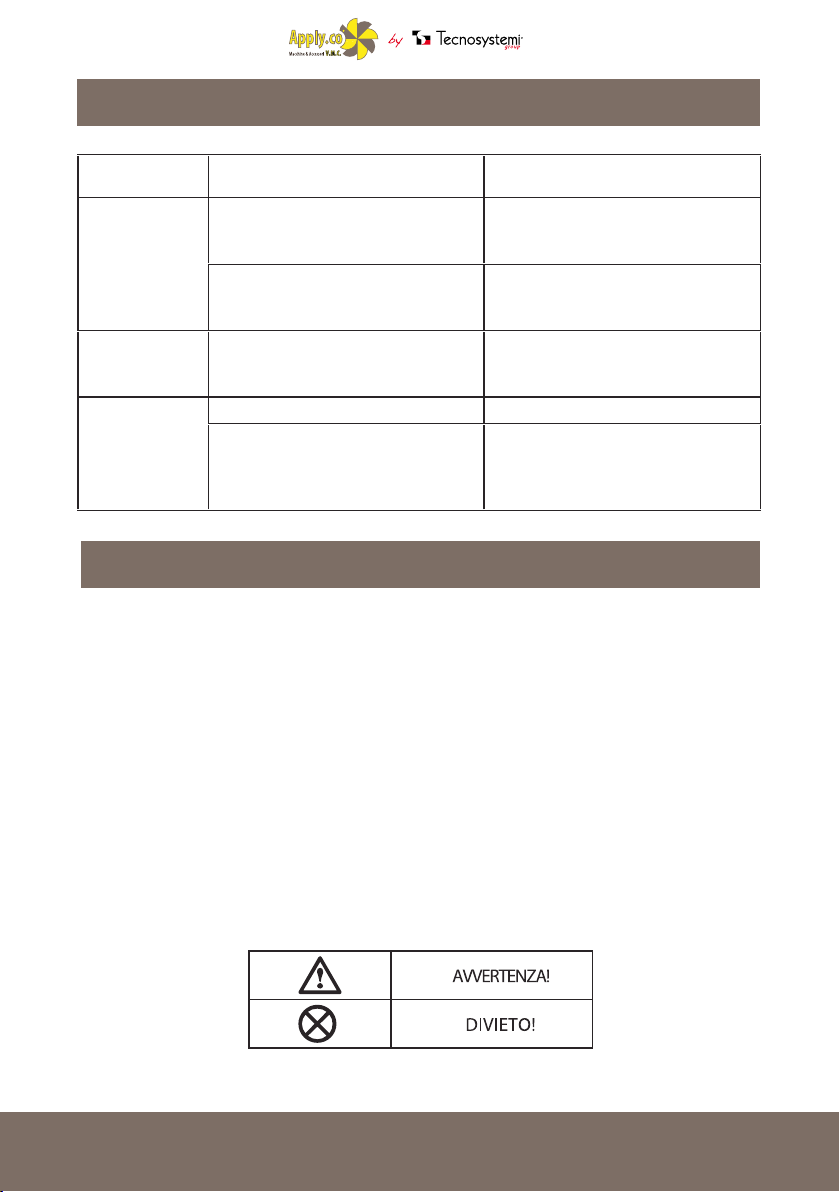
When transferring the command of the unit, the user manual must be handed over to the receiving
user. Symbols used in the manual:
3
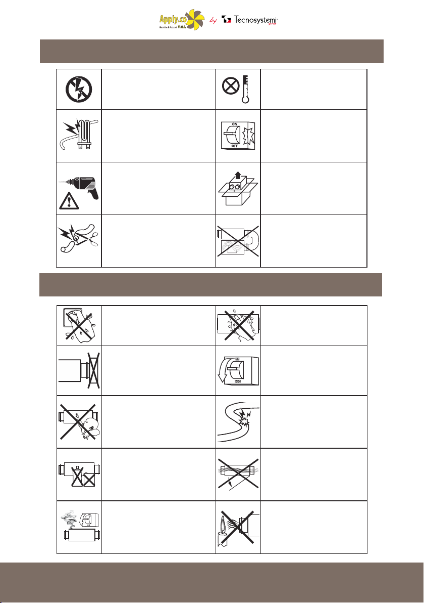
PRECAUTIONS DURING ASSEMBLY
The unit must be disconnected
from the power supply before every
installation or repair.
Do not place heaters or other devices
in the vicinity of the power cable of the
ventilation unit.
When installing the unit, follow
the specic safety requirements for
electrical equipment.
Do not change the length of the power
cable at your discretion. Do not bend
the power cable. Do not damage the
power cable.
Do not use the unit outside the
temperature range given in the user
manual, or in atmospheres that are
aggressive or at risk of explosion.
Do not use damaged equipment
or wires to connect the unit to the
mains.
Remove the unit from the packaging
carefully.
Use the ventilation unit only
according to the manufacturer's
specications.
OPERATIVE SAFETY PRECAUTIONS
Do not touch the controls or remote
control with wet hands. Do not
perform maintenance on the
ventilation unit with wet hands.
Do not block the air duct when the
ventilation unit is on
Do not wash the ventilation unit
with water. Protect the electrical
parts of the ventilation unit from
water.
Before maintenance, unplug the
ventilation unit from the mains.
Do not allow children to use the
ventilation unit.
Keep explosives and ammable
products away from the ventilation
Should the ventilation unit give out
unusual noises or smoke, unplug it
from the mains and contact customer
service.
4
Do not damage the power cable
with the ventilation unit in use. Do
not place any objects on the power
cable.
Do not open the ventilation unit
when on.
Do not let the air exiting the
ventilation unit point towards open
ames, candles, etc.
4
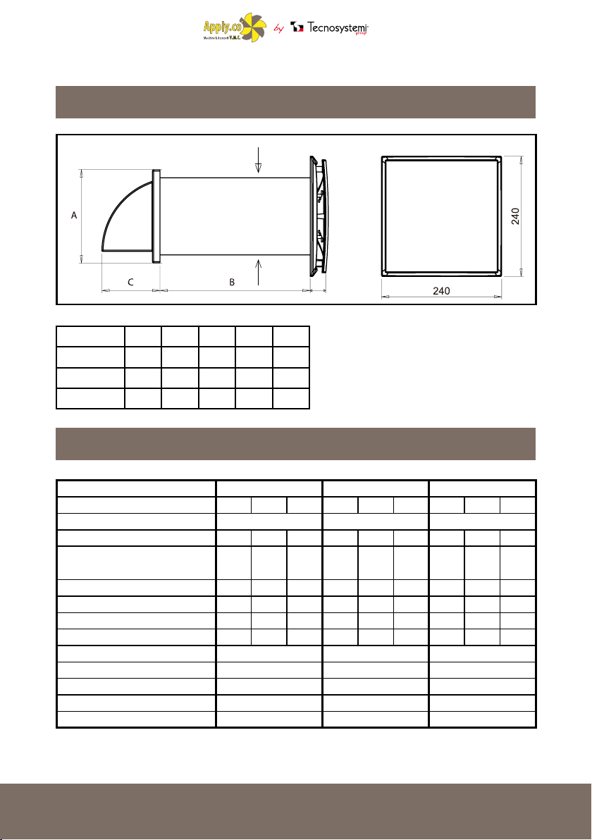
VENTILATION UNIT OVERALL EXTERNAL DIMENSIONS
DIMENSIONS (MM)
Ø
E
CODE A B C Ø E
11104038A 154 500 86 100 35
11104038C 186 500 101 125 35
11104038E 186 500 101 150 35
VENTILATION UNIT TECHNICAL SPECIFICATIONS
MODEL: PICO HP2 - 30 PICO HP2 - 55 PICO HP2 - 80
SPEED 1 2 3 1 2 3 1 2 3
SUPPLY VOLTAGE 12VDC 12VDC 12VDC
OUTPUT (W) 0.46 0.51 0.57 0.85 0.9 1.1 1.9 2 2.3
MAX. CURRENT CONSUMPTION
(mA)
MAX. AIR CAPACITY (m³/h) 26 28.5 32 40 45 50 65 72 80
RPM (min-1) 1863 2070 2300 2106 2340 2600 2754 3060 3400
SOUND PRESSURE AT 1m (dB(A)) 17 19 21 21 23 25 24 26 28
ACOUSTIC PRESSURE AT 3 m (dB(A)) 15 17 19 19 21 23 22 24 26
MAX. AIR TEMPERATURE (°C) FROM -10ºC to +50 FROM -10ºC to +50 FROM -10ºC to +50
REGENERATOR EFFICIENCY ≤90% ≤90% ≤90%
EXCHANGE-BOX MATERIAL CERAMIC CERAMIC CERAMIC
TUBE DIMENSIONS (mm) Ø 100 Ø 125 Ø 150
PROTECTION IP 24 IP 24 IP 24
38 42 47 65.5 73 81 154 171 190
5
OPERATION OF THE PICO HP2
The ventilation unit consists of a xed-length circular air duct, a ventilation unit, and an outdoor grill.
The two motors, two lters and the exchanger are located within the inner duct.
The lters are designed to purify the intake air and prevent the entry of objects foreign to the exchanger
and fans.
The ventilation unit generates an audible alarm to remind you to clean or replace the lter every 1,500
hours of operation.
The ceramic heat exchanger uses the heat energy in the extracted air to heat the incoming air ow.
The exchanger is equipped with a pull-cord inside to facilitate its extraction from the ventilator. The
heat exchanger is installed on an insulating material, used also as a sealant.
The ventilation unit must be installed on the inner side of the wall.
The outside grill must be installed on the wall exterior, to prevent water and other objects from
entering the ventilation unit.
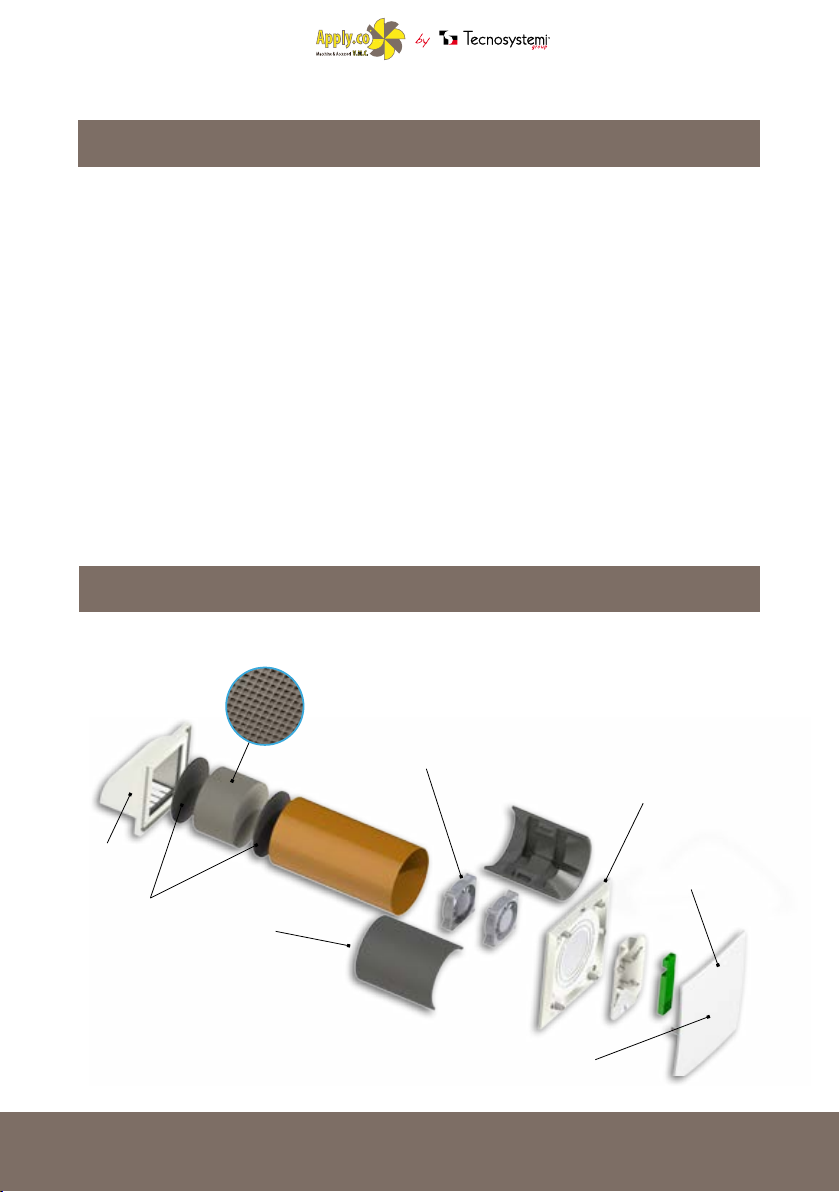
CONSTRUCTION DETAIL
DETAIL OF EXCHANGE BOX
IN CERAMIC MATERIAL
EXTERNAL
GRID
FILTERS
6
FANS BODY
THREE-SPEED
MOTORS
EXTRA-SLIM
INTERNAL GRID
LED FUNCTION
SET
DESIGN AIR INTAKE
WITH QUICK-RELEASE FOR
MAINTENANCE
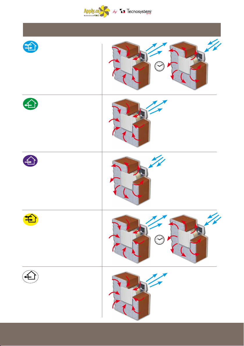
OPERATING MODE
RECOVERY UNIT
THE UNIT RUNS FOR 70 SECONDS
IN EXTRACTION MODE AND FOR 70
SECONDS IN INTAKE MODE, WITH
THREE-SPEED CONTROL
EXTRACTION
THE UNIT WORKS IN ONLY
EXTRACTING THE AIR FROM THE
INTERIORS, WITH THREE-SPEED
CONTROL
INTAKE
THE UNIT WORKS ONLY IN INTAKE
MODE BY EXTRACTING AIR TO THE
OUTSIDE AND SUCKING IT INSIDE,
WITH 3-SPEED CONTROL
70 secs.
AUTO1
AUTO1
THE UNIT IS IN STAND-BY MODE.
THE UNIT IS IN STAND-BY MODE.
WHEN THE ENVIRONMENT AIR
EXCEEDS THE PRE-SET HUMIDITY
LEVEL, THE UNIT STARTS TO
OPERATE IN HEAT-RECOVERY
MODE UNTIL THE HUMIDITY
RETURNS TO THE SET LEVEL
AUTO2
AUTO2
THE UNIT IS IN STAND-BY MODE.
WHEN THE ENVIRONMENT AIR
EXCEEDS THE PRE-SET HUMIDITY
LEVEL, THE UNIT STARTS TO
OPERATE IN EXTRACTION MODE
ONLY UNTIL HUMIDITY RETURNS
TO THE SET LEVEL
70 secs.
7
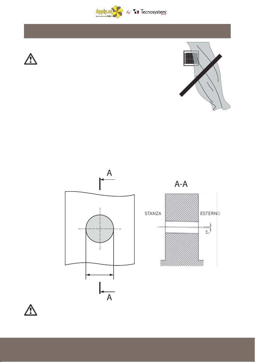
INSTALLATION AND SETUP
WARNING!
THE VENTILATION UNIT MUST NOT BE INSTALLED WHERE
THE AIR DUCT CAN BE BLOCKED BY SHUTTERS, BLINDS, ETC.
TO PREVENT DUST DEPOSITING AND ACCUMULATING. ALSO
CURTAINS MAY BLOCK THE NORMAL FLOW OF AIR IN THE
ROOM, MAKING THE UNIT'S OPERATION INEFFECTIVE.
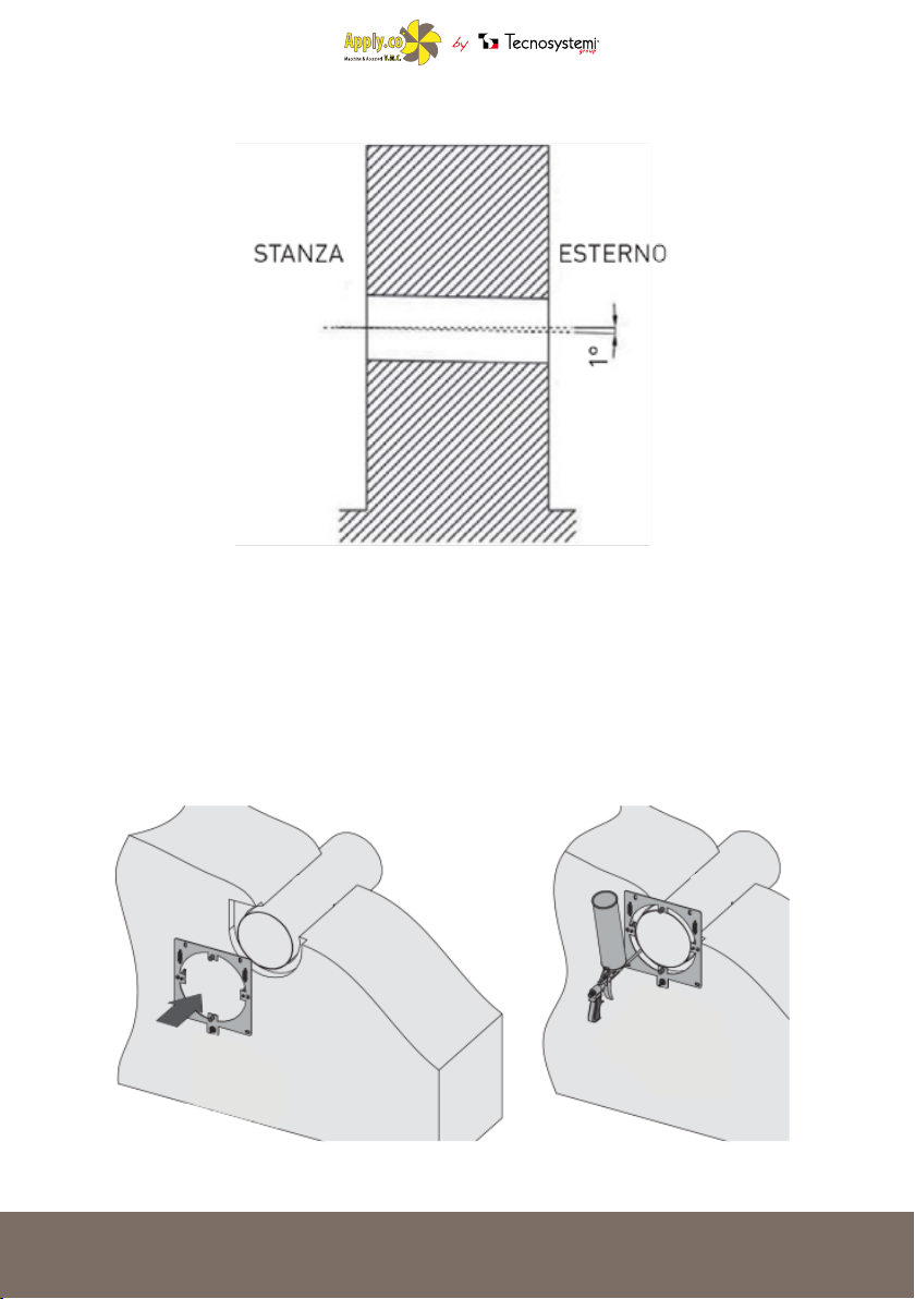
1. To mount the ventilation unit, prepare a round throughhole in the wall depending in the "Pico HP2 model" you
have purchased, having a 1° inclination downwards
towards the outside.
The size of the hole is shown in the gure below.
ø 100 - 125-150 mm
WARNING!
DO NOT INSTALL THE UNIT ABOVE DELICATE FURNITURE OR PICTURES/PAINTINGS.
DO NOT PLACE THE DEVICE ABOVE OR NEAR THERMOSTATS .
8
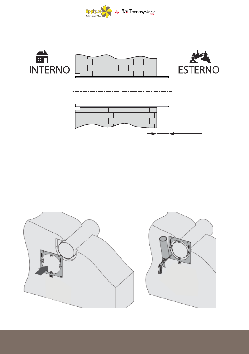
3. Insert the pipe into the wall. The air duct must protrude by the distance indicated below:
5 mm
4. Attach the mounting plate by following the diagram on page 12.
Prepare the four mounting holes and secure the mounting plate onto the part with four 4x40 screws,
and four raw-plugs 6x40 (included).
Align the air duct with respect to the mounting plate; now ll in the spaces between the wall and the
duct with silicone. The air duct does not protrude from the surface of the mounting plate.
9

5. Insert the lter, the ceramic exchanger, and another lter in consecutive order, into the air-duct.
6. Fit the ventilation unit onto the mounting plate.
6. Fit the ventilation unit onto the mounting plate.
INSTALLING THE INTAKE GRID
1. Mark the xing holes for the external ventilation grid and drill them. For convenience, use the back
of the grid.
PICO HP2 30
PICO HP2 55
PICO HP2 80
10

2. Insert the 6x40 raw-plugs (included) into the holes.
3. Now remove the external grid to allow access to the xing holes.
Remove the upper part of the external ventilation grid.
4. Secure the back of the grid to the wall with the 4x40 screws
included.
5. Fit the upper part of the grid.
11

CONNECTING TO THE MAINS
DISCONNECT THE VENTILATION UNIT FROM THE POWER SUPPLY BEFORE ANY
ELECTRICAL INSTALLATION OPERATION. CONNECT THE VENTILATION UNIT TO AN
OUTLET PROPERLY INSTALLED WITH TERMINAL GROUND. DO NOT MAKE ANY CHANGE
TO THE INTERNAL CONNECTIONS: IT WOULD CAUSE THE LOSS OF WARRANTY
The ventilation unit is calibrated for connection to single-phase AC mains supply 230 V/50 Hz with
a 12 VDC transformer (supplied). To facilitate cable routing, the unit comes with a pre-wired power
cable.
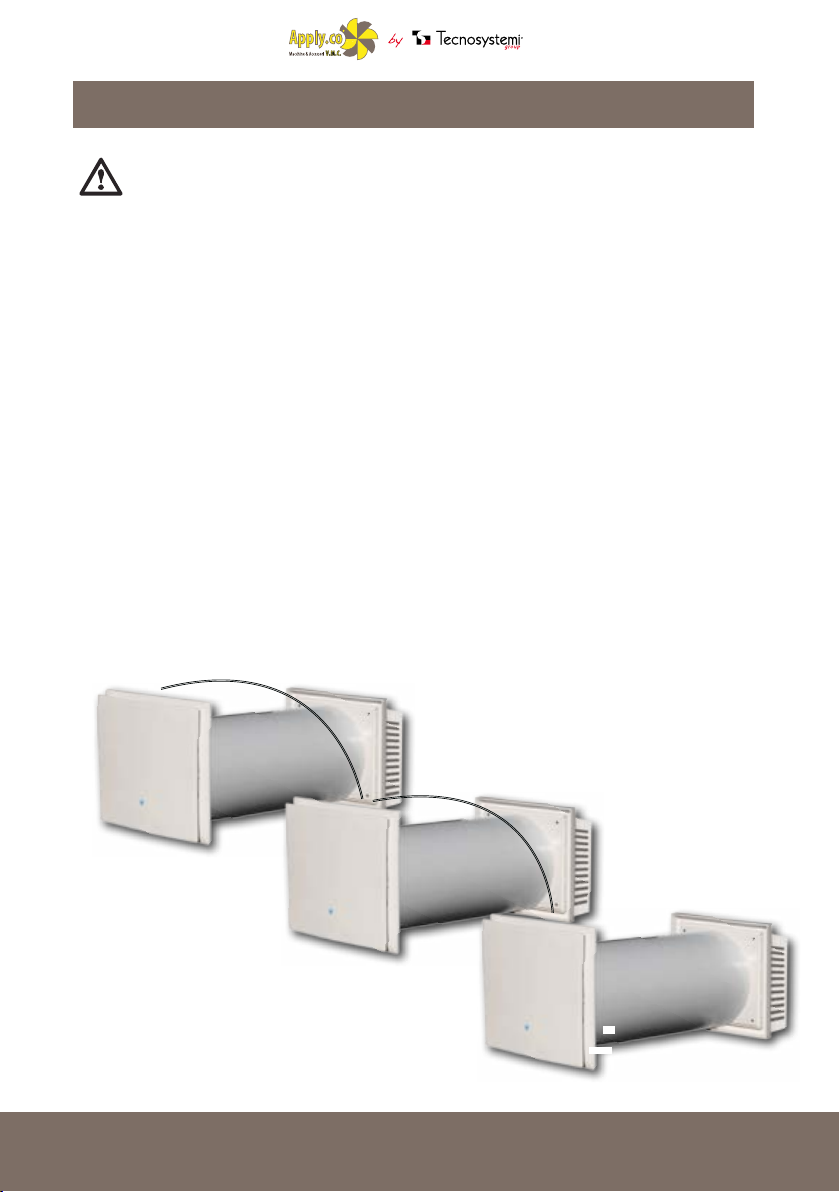
CONNECTION OF THE UNIT IN SERIES
When the ventilation units are connected in series, all the connected units are controlled to the rst
unit and a common remote control. To connect the ventilation units in series, connect the output
contact of the rst unit to the outlet of the input contact of the second one.
Now connect the second unit to the third unit in the same way; up to 10 ventilation units can be
connected in series.
Unplug the power cable while connecting the second, third, etc. units.
CONNECTING SEVERAL UNITS IN SERIES (REAR VIEW)
12

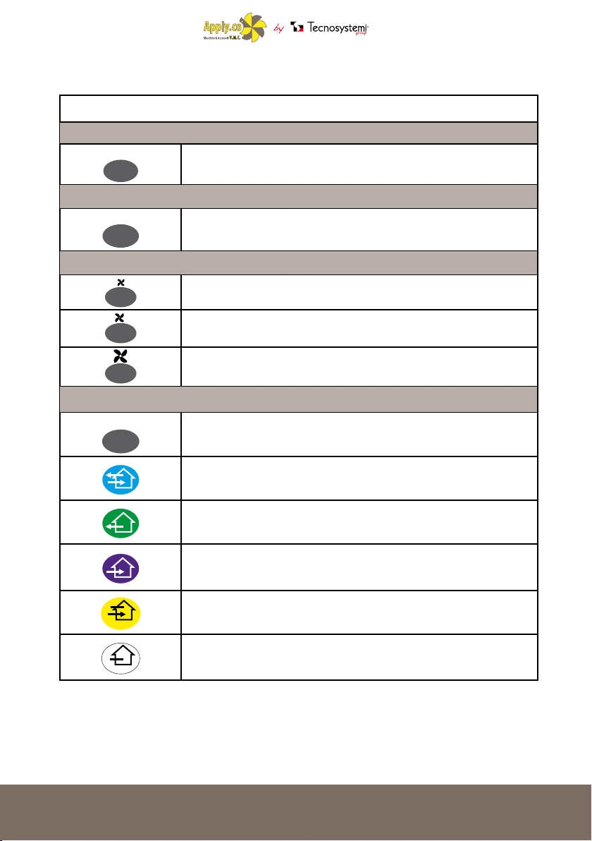
USING REMOTE CONTROL
The ventilation unit is controlled by a remote control. The remote control has the capacity for more
commands.
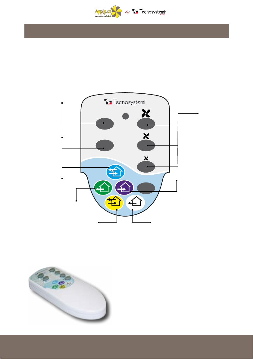
REMOTE CONTROL DEVICE
Ventilation unit ON
Ventilation unit OFF
the appliance runs for 70 seconds in
extraction mode and for 70 seconds in
intake, with the possibility to adjust the
Recovery unit
three-speeds
unit works only extracts the air from the
interiors, with 3-speed control.
The unit is in stand-by mode. when the
humidity level, the unit starts to operate
in heat-recovery mode until the humidity
Extraction
Auto 1
environment air exceeds the pre-set
returns to the set level
ON
OFF
AUTO1 AUTO2
MODE
Auto 2
The unit is in stand-by mode. when the
environment air exceeds the pre-set
humidity level, the unit starts to operate
in heat-recovery mode until the humidity
returns to the set level
Change speed
Intake
unit works in intake mode only, extracting
air to the outside and sucking it inside,
with 3-speed control.
13

1. Switching on
ON
2. Switching o
OFF
3. Speed setting
4. Operating mode
MODE
REMOTE CONTROL DEVICE
DESCRIPTION OF REMOTE-CONTROL BUTTONS
ON
OFF
First speed.
Second speed.
Third speed.
MODE
Allows you to select the following modes
Recovery unit
The unit runs for 70 seconds in extraction mode and for 70 seconds in intake mode, with 3-speed
control.
AUTO2
Extraction
The unit works in only extracting the air from the interiors, with three-speed control
’
Intake
Unit works in intake mode only, extracting air to the outside and sucking it inside, with
3-speed control.
Auto1
The unit is in stand-by mode. when the environment air exceeds the pre-set humidity level,
the unit starts to operate in heat-recovery mode until the humidity returns to the set level
Auto2
the unit is in stand-by mode. When the environment air exceeds the pre-set humidity level,
the unit starts to operate in extraction only mode only until the humidity level return to the
level required
d
14

Vers. 01 - 29/01/2016
USER MANUAL
100
WALL-MOUNTED STATIC EXTRACTION UNIT WITH MECHANICAL CROSS-
FLOW
AND HEAT RECOVERY

VENTILATION UNIT OVERALL EXTERNAL DIMENSIONS
DIMENSIONS (MM)
51
VENTILATION UNIT TECHNICAL SPECIFICATIONS
SPEED MIN. 1 MED. 2 MAX. 3
SUPPLY VOLTAGE 12Vdc
POWER (W) 3.7 4.1 4.6
MAX. POWER CONSUMPTION (A) 308 342 380
MAX. AIR CAPACITY (m³/h) 75 87 93
RPM (min-1) 2754 3060 3400
SOUND PRESSURE AT 1m (dB(A)) 31 33 35
ACOUSTIC PRESSURE AT 3 m (dB(A)) 29 31 33
MAX. AIR TEMPERATURE (°C) FROM -10°C TO +50°C
REGENERATOR EFFICIENCY ≤95%
EXCHANGE-BOX MATERIAL POLYESTER
TUBE DIMENSIONS (mm) Ø 200
PROTECTION IP 24
16

PICO RECO 100 OPERATION
The ventilation unit consists of a xed-length circular air duct, a ventilation unit, and an outdoor grill.
The two motors, two lters and the exchanger are located within the inner duct.
The lters are designed to purify the intake air and prevent the entry of objects foreign to the exchanger
and fans.
The ventilation unit generates an audible alarm to remind you to clean or replace the lter every 90
hours of operation.
The high eciency polyester cross-ow exchanger exploits thermal energy of the air extracted from
outside to warm up the air inside.
The heat exchanger is installed on an insulating material, used also as a sealant.
The ventilation unit must be installed on the inner side of the wall.
The external grill must be installed on the wall exterior, to prevent water and other objects from
entering the ventilation unit.
CONSTRUCTION DETAIL
THREE-SPEED
MOTORS
EXTRA-SLIM
INTERNAL GRID
DESIGN AIR INTAKE
WITH QUICK-RELEASE FOR
MAINTENANCE
EXTERNAL
GRID
FILTERS
HIGH-EFFICIENCY MECHANI-
CAL CROSS-FLOW
EXCHANGE BOX
AIR
DEFLECTOR
LED FUNCTION
SET
1717
17

OPERATING MODE
RECOVERY UNIT
THE UNIT RECOVERS HEAT (BY
SIMULTANEOUS EXTRACTION
AND INTAKE) AND HAS 3-SPEED
CONTROL
EXTRACTION
THE UNIT WORKS IN ONLY
EXTRACTING THE AIR FROM THE
INTERIORS, WITH THREE-SPEED
CONTROL
INTAKE
THE UNIT WORKS ONLY IN INTAKE
MODE BY EXTRACTING AIR TO THE
OUTSIDE AND SUCKING IT INSIDE,
WITH 3-SPEED CONTROL
18
AUTO1
AUTO1
THE UNIT IS IN STAND-BY MODE.
WHEN THE ENVIRONMENT AIR
EXCEEDS THE PRE-SET HUMIDITY
LEVEL, THE UNIT STARTS TO
OPERATE IN HEAT-RECOVERY
MODE UNTIL THE HUMIDITY
RETURNS TO THE SET LEVEL
AUTO2
AUTO2
THE UNIT IS IN STAND-BY MODE.
WHEN THE ENVIRONMENT AIR
EXCEEDS THE PRE-SET HUMIDITY
LEVEL, THE UNIT STARTS TO
OPERATE IN EXTRACTION-ONLY
MODE UNTIL HUMIDITY RETURNS
TO THE SET LEVEL.
3. Install the duct through the wall with an inclination of 1 ° to the outside environment.
4. Attach the mounting plate by following the diagram on page 12.
Prepare the four mounting holes and secure the mounting plate onto the part with four 4x40 screws,
and four raw-plugs 6x40 (included).
Align the air duct with respect to the mounting plate; now ll in the spaces between the wall and the
duct with silicone. The air duct does not protrude from the surface of the mounting plate.
19
19

5. Insert the lter, the ceramic exchanger, and another lter in consecutive order, into the air-duct.
6. Fit the ventilation unit onto the mounting plate.
6. Fit the ventilation unit onto the mounting plate.
20

INSTALLING THE INTAKE GRID
1. Mark the xing holes for the external ventilation grid and drill for 6x40 plug. For convenience, use
the back of the grid.
2. Insert the 6x40 raw-plugs (included) into the holes.
3. Now remove the external grid to allow access to the xing holes.
Remove the upper part of the external ventilation grid.
4. Secure the back of the grid to the wall with the 4x40 screws
included.
5. Fit the upper part of the grid.
21
21
CONNECTING TO THE MAINS
DISCONNECT THE VENTILATION UNIT FROM THE POWER SUPPLY BEFORE ANY
ELECTRICAL INSTALLATION OPERATION. CONNECT THE VENTILATION UNIT TO AN
OUTLET PROPERLY INSTALLED WITH TERMINAL GROUND. DO NOT MAKE ANY CHANGE
TO THE INTERNAL CONNECTIONS: IT WOULD CAUSE THE LOSS OF WARRANTY
The ventilation unit is calibrated for connection to the single-phase AC mains supply 230 V / 50 Hz
using 12 VDC transformer. To facilitate cable routing, the ventilation unit comes with a pre-wired
power cord and a plug. Connect the ventilation unit to the mains through the circuit breaker with
integrated magnetic stripe in the wiring system.
CONNECTION OF THE UNIT IN SERIES
When the ventilation units are connected in series, all the connected units are controlled to the rst
unit and a common remote control. To connect the ventilation units in series, connect the socket of
the mounting plate output contact of the rst ventilation unit with the outlet of the input contact of
the second plate of the ventilation unit assembly.
Now connect the second unit to the third unit in the same way; up to 10 ventilation units can be
connected in series.
Unplug the power cable while connecting the second, third, etc. units.
CONNECTING SEVERAL UNITS IN SERIES (REAR VIEW)
22
USING REMOTE CONTROL
The ventilation unit is controlled by a remote control. The remote control has the capacity for more
commands.
REMOTE CONTROL DEVICE
Ventilation unit ON
Ventilation unit OFF
the unit recovers heat (by simultaneous
extraction and intake) and has 3-speed
Recovery unit
control
the unit works in only extracting the air
from the interiors, with three-speed control
the unit is in stand-by mode. When the
humidity level, the unit starts to operate
in heat-recovery mode, to return humidity
Extraction
Auto 1
environment air exceeds the pre-set
to the set level
ON
OFF
AUTO1 AUTO2
MODE
Auto 2
the unit is in stand-by mode. When the
environment air exceeds the pre-set
humidity level, the unit starts to operate in
extraction mode only, to return humidity
to the set level
Change speed
Intake
unit works in intake mode only, extracting
air to the outside and sucking it inside,
with 3-speed control.
23
23
1. Switching on
ON
2. Switching o
OFF
3. Speed settings
4. Operating mode
MODE
REMOTE CONTROL DEVICE
DESCRIPTION OF REMOTE-CONTROL BUTTONS
ON
OFF
First speed.
Second speed.
Third speed.
MODE
Allows you to select the following modes
Recovery unit
The unit recovers heat (by simultaneous extraction and intake) and has 3-speed control
24
AUTO2
Extraction
The unit works in only extracting the air from the interiors, with three-speed adjustment
’
Intake
Unit works in intake mode only, extracting air to the outsideand sucking it inside, with
3-speed control.
Auto1
the unit is in stand-by mode. When the environment air exceeds the pre-set humidity level,
the unit starts to operate in recovery mode, to return humidity to the set level
Auto2
the unit is in stand-by mode. When the environment air exceeds the pre-set humidity level,
the unit starts to operate in extraction mode only, to return humidity to the set leve
l
MAINTENANCE
UNPLUG THE UNIT FROM THE MAINS BEFORE STARTING MAINTENANCE.
Maintenance of the ventilation unit means regular cleaning of its surfaces from dust and clean, and
the replacement of its lters.
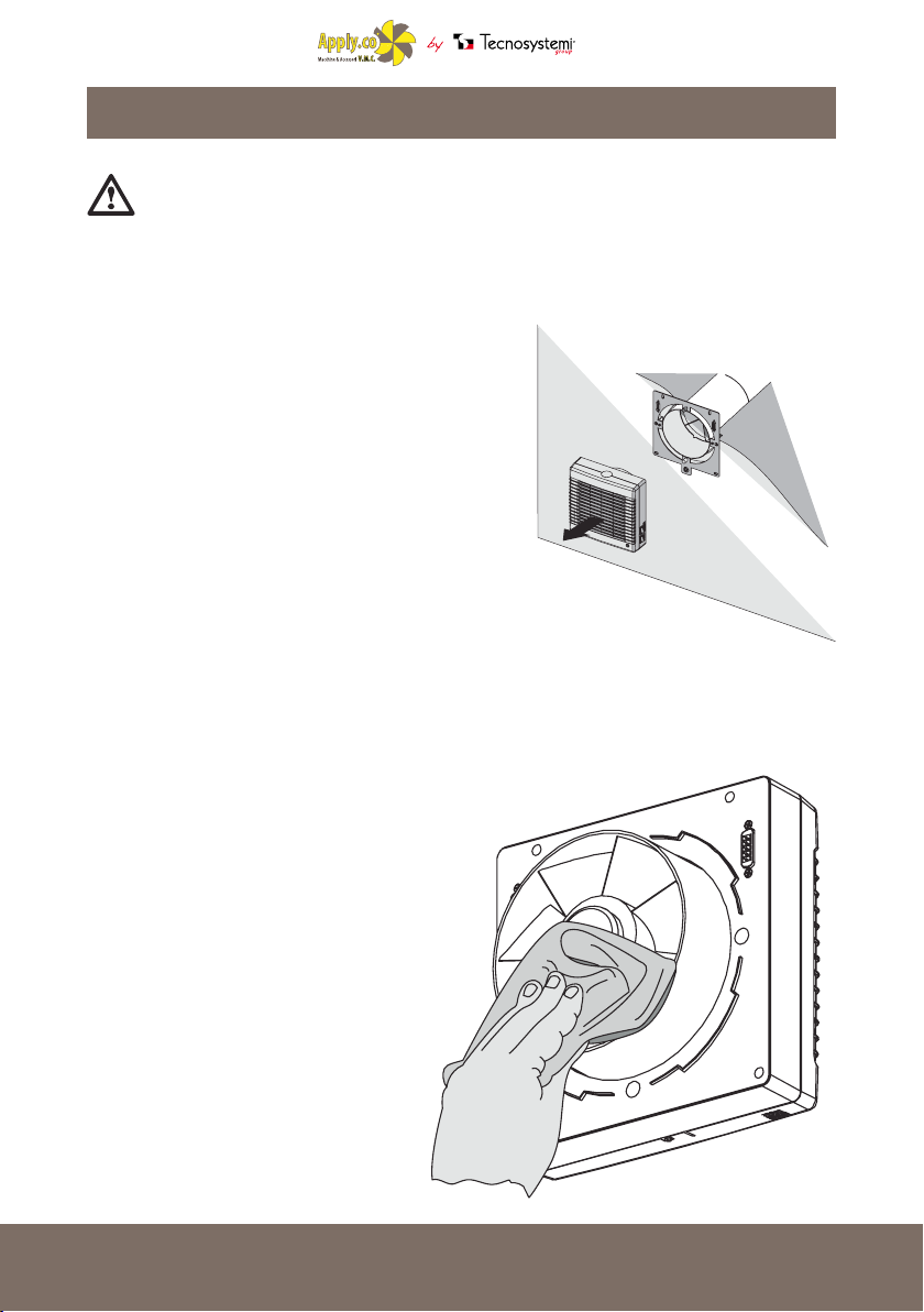
1. Fan maintenance (once a year).
Pull on the ventilation unit to remove.
Clean the impeller blades. To dust,
use a soft brush, cloth or vacuum cleaner.
Do not use water, abrasive cleaners, solvents or sharp
objects. The impeller blades must be cleaned
once a year.
25

2. Regenerator and lter maintenance (every 1,500
hours).
Remove the air-ow rectier.
Remove the lter in front of the regenerator.
Pull the regenerator cord to remove the air duct from
the regenerator.
Be careful when removing the regenerator, to avoid
damage. Remove the regenerator rst, then the lter.
Clean the lter when it gets dirty (every 1,500 hours).
After about 1,500 hours of operation, the unit emits a
red light signal as a reminder of the need to replace or
clean the lter. The signal continues until maintenance
is completed.
Clean the lters, dry them and insert the dry lters into
the duct.
Aspiration is permitted.
The duration of the lter is approximately three years.
Contact the seller for replacement lters.
Even technical maintenance cannot completely prevent
the accumulation of dirt on the regenerator unit.
Have the regenerator cleaned regularly to ensure high
heat-transfer eciency.
Clean the regenerator with a vacuum cleaner at least
once a year.
To reset the operating-time counter, insert the lters
and regenerator into the ventilation unit, then hold the
ON/OFF button pressed for 10 secs. until you hear a
long tone; then release.
3. Outdoor-grill maintenance (once a year).
The external ventilation grid can become clogged with leaves
or other objects that impede the smooth operation of the unit.
Check the ventilation grid twice a year, and clean it as often as
necessary.
To clean the ventilation grid, remove and clean the ventilation
cap and air duct.
26
26

TRANSPORTATION AND STORAGE
The unit should be stored in its original packaging in a ventilated area at a temperature of +10°C to
+40 ° C.
The air must not contain any aggressive vapours or chemical mixtures that can corrode, or compromise
the integrity of, the connections.
For handling, only use suitable lifting equipment to prevent damage to the unit (dropping or excessive
swing). Follow the applicable regulations regarding transport, according to the type of load.
The units can be transported by any means as long as adequate protection is provided against weather
and mechanical damage. Avoid bumps and collisions during transport and handling operations.
WARRANTY
The warranty lasts for two (2) years from the date of delivery, and covers material defects with the exception of
goods not manufactured by the supplier. The warranty does not apply to defects caused by:
• unsuitable transport;
• the negligent or improper use of the product, or any use thereof that fails to comply with the instructions and/
or manuals of installation, use and maintenance;
• non-observance of the product’s technical specications
• repairs or modications carried out by the client or by third parties without the supplier’s prior written
authorization
• lack of, or unsuitability of, maintenance
• anything else not relating to original material or manufacturing defects.
• provided that the customer's complaint is covered by the warranty and notied in the terms and conditions
requested by the supplier, the latter will, at its discretion, replace or repair each product or parts thereof that
present aws or e or repair each faulty product or part/s thereof
• the warranty does not cover damage and/or defects of products arising from anomalies caused by, or related to,
parts that have been assembled/added directly by the customer or by the end consumer.
DISPOSAL
At the end of its life, the product must not be disposed of together with normal domestic waste. It may be disposed
of by delivering
it to an appropriate state-run recycling centre or to an approved private service
provider. To underline the duty to properly dispose of household appliances, the product indicates the symbol of the
mobile waste bin as crossed (not to be used to dispose of the product).
27
27
 Loading...