

Tecnosystemi ACD100002, ACD100001, ACD100003, ACD100005, ACD100004 User Manual
...
USER MANUAL
Accessories for
Air Conditioning
Air Curtains and
Accessories
Multi - Zone
Air Control System
01
"PICO WI HP2" - WALL-MOUNTED, STATIC INTAKE /
EXTRACTOR FAN WITH HEAT RECOVERY, EQUIPPED WITH EXTERNAL
POWER SUPPLY OR WITH BUILT-IN POWER SUPPLY
ACD100001 - ACD100002 - ACD100003 - ACD100004 - ACD100005 - ACD100006
ACD100007 - ACD100008 - ACD100009 - ACD100010 - ACD100011 - ACD100012
ACD100013 - ACD100014 - ACD100015 - ACD100016 - ACD100017 - ACD100018
"PICO WI RECO 100" - WALL-MOUNTED CROSS FLOW STATIC INTAKE
EXTRACTOR FAN WITH HEAT RECOVERY EQUIPPED WITH EXTERNAL
POWER SUPPLY OR WITH BUILT-IN POWER SUPPLY
ACD100019 - ACD100020 - ACD100021 - ACD100022 - ACD100023 - ACD100024
C
-
C CO2
- -
C CO2
C
-
WI-FI COMFORT CO2
- -
Accessories for
Air Conditioning
Air Curtains and
Accessories
Multi - Zone
Air Control System
INTRODUCTION
02
This manual includes the technical description, operation, installation and assembly instructions,
technical data for the intake extractor unit with energy regeneration “PICO HP2”, “PICO RECO
100”, hereinafter referred to as recovery unit.
SAFETY REQUIREMENTS
Read the user manual carefully before use and installation of heat reversible recovery unit with
individual chamber with energy regeneration.
The installation and the operation of the recovery unit must be carried out in compliance with the
user manual, as well as with applicable legislations, local and national laws and technical and
electrical regulations. The warnings, contained in the user manual, should be heeded, as they
contain vital information for personal safety.
Failure to follow the safety rules can result in damage to the recovery unit. Read this
manual carefully and keep it for as long as the recovery unit is used.
Legend of symbols used in the manual:
WARNING
PROHIBITION
USE OF THE RECOVERY UNIT
The recovery unit was designed to ensure the air exchange in apartments, holiday farms, hotels,
bars and, in general, domestic and public places.
The recovery unit is tted with a ceramic exchanger which allows the air recirculation thanks to
the energy regeneration with the heat from the intake air.
The recovery unit was designed to be installed in premises on walls with a thickness between 310 mm
and 500 mm (optional tube L=1,500 mm), for the “Pico Reco 100”, the minimum thickness is 370 mm.
The recovery unit was tested for continuous operation connected always to be mains supply.
The transported air must not contain ammable or explosive mixtures, chemical substance
vapours, large dust particles, soot and oil particles, dangerous substances, brous
materials, pathogenic agents or other harmful substances.
THE RECOVERY UNIT WAS NOT DESIGNED FOR USE BY CHILDREN, PERSONS WITH
PHYSICAL OR MENTAL DISABILITIES, PERSONS WITH SENSORY DISABILITIES, OR
PERSONS WITHOUT ADEQUATE QUALIFICATIONS.
THE INSTALLATION AND CONNECTION OPERATIONS CAN BE PERFORMED ONLY BY
QUALIFIED PERSONNEL AFTER FOLLOWING THE ADEQUATE SAFETY TRAINING.
UNATTENDED CHILDREN SHOULD NOT BE ALLOWED ACCESS TO THE SITES WHERE THE
FAN IS INSTALLED.
MAIN TECHNICAL PARAMETERS
The recovery unit was designed for application within premises with a room temperature varying
from -20°C to +50°C and relative humidity of up to 80%.
Accessories for
Air Conditioning
Air Curtains and
Accessories
Multi - Zone
Air Control System
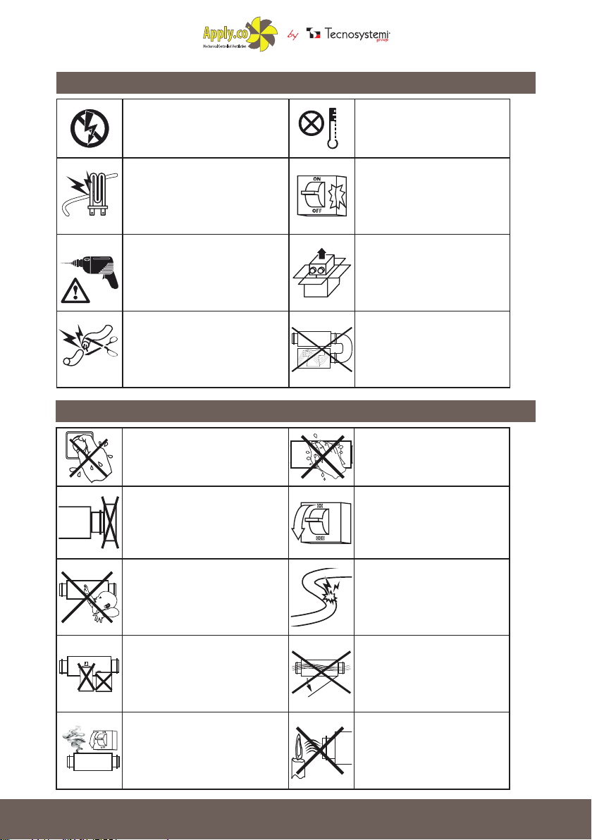
ASSEMBLY WARNINGS
03
The recovery unit must be
disconnected from the mains
supply before carrying out any
installation or repair operation.
The recovery unit must not be used
outside the temperature range,
indicated in the user manual,
or in aggressive or explosive
atmospheres.
Do not place any radiators or other
devices near the power cord of the
recovery unit.
When installing the recovery
unit, follow the specic safety
regulations for electrical
equipment.
Do not change the length of the
power cord at your own discretion.
Do not bend the power cord. Do
not damage the power cord.
SAFETY OPERATING WARNINGS
Do not touch the controls and the
remote controls with wet hands. Do
not perform maintenance operations
on the recovery unit with wet hands.
Do not block the air duct, when the
recovery unit is on.
Do not let children use the
recovery unit.
Do not use damaged equipment
or wires to connect the recovery
unit to the mains.
Carefully remove the recovery
unit from the packaging.
Use the recovery unit only
in accordance with the
manufacturer's specications.
Do not wash the recovery unit
with water. Protect the parts of
the recovery unit from water
seepage.
Disconnect the recovery
unit from the mains before
maintenance.
Do not damage the power cord
when using the recovery unit.
Do not place objects on the
power cord.
Keep explosive and ammable
products away from the recovery
unit.
In the event of unusual noises or
smoke, disconnect the recovery
unit from the wall outlet and contact
customer service.
Do not open the recovery unit
during operation.
Make sure that the air emitted
by the recovery unit is not
directed at naked ames or
candles.

Accessories for
Air Conditioning
Air Curtains and
Accessories
Multi - Zone
Air Control System
DIMENSIONS “PICO HP2”
04
Ø
F
DIMENSIONS AND MODELS
D
A B C Ø D E F
(mm) (mm) (mm) (mm) (mm) (mm) (mm)
E
ACD100001 / ACD100004 154 500 86 103 35 240 240
ACD100002 / ACD100005 186 500 101 128 35 240 240
ACD100003 / ACD100006 186 500 101 153 35 240 240
DIMENSIONS AND MODELS
C
-
ACD100007 / ACD100010 154 500 86 103 35 240 240
A B C Ø D E F
(mm) (mm) (mm) (mm) (mm) (mm) (mm)
ACD100008 / ACD100011 186 500 101 128 35 240 240
ACD100009 / ACD100012 186 500 101 153 35 240 240
A B C Ø D E F
(mm) (mm) (mm) (mm) (mm) (mm) (mm)
C CO2
- -
DIMENSIONS AND MODELS
ACD100013 / ACD100016 154 500 86 103 35 240 240
ACD100014 / ACD100017 186 500 101 128 35 240 240
ACD100015 / ACD100018 186 500 101 153 35 240 240
MODEL PICO HP2 30 WI PICO HP2 55 WI PICO HP2 80 WI
SPEED 1 2 3 1 2 3 1 2 3
SUPPLY VOLTAGE 230 Vac
POWER (W) 1,3 1,4 1,4 1,3 1,6 2,2 1,7 2,6 3,6
MAXIMUM CURRENT CONSUMED
(mA)
38 42 47 65,5 73 81 162 180 200
MAXIMUM AIR FLOW RATE (m³/h) 23 25 28 23 35 46 39 64 74
RPM (min-1) 1863 2070 2300 2106 2340 2600 2350 2610 2900
SOUND PRESSURE AT 1m (dB(A) 27 28 29 24 28 34 28 35 39
SOUND PRESSURE AT 3 m (dB(A) 25 26 27 23 26 32 26 33 37
MAXIMUM AIR TEMPERATURE (°C) FROM -10 TO +50 FROM -10 TO +50 FROM -10 TO +50
REGENERATOR EFFICIENCY ≤90% ≤90% ≤90%
HEAT EXCHANGE FILL MEDIA CERAMIC CERAMIC CERAMIC
TUBE DIMENSIONS (mm) Ø 103 Ø 128 Ø 153
PROTECTION IP 24 IP 24 IP 24
Accessories for
Air Conditioning
Air Curtains and
Accessories
Multi - Zone
Air Control System
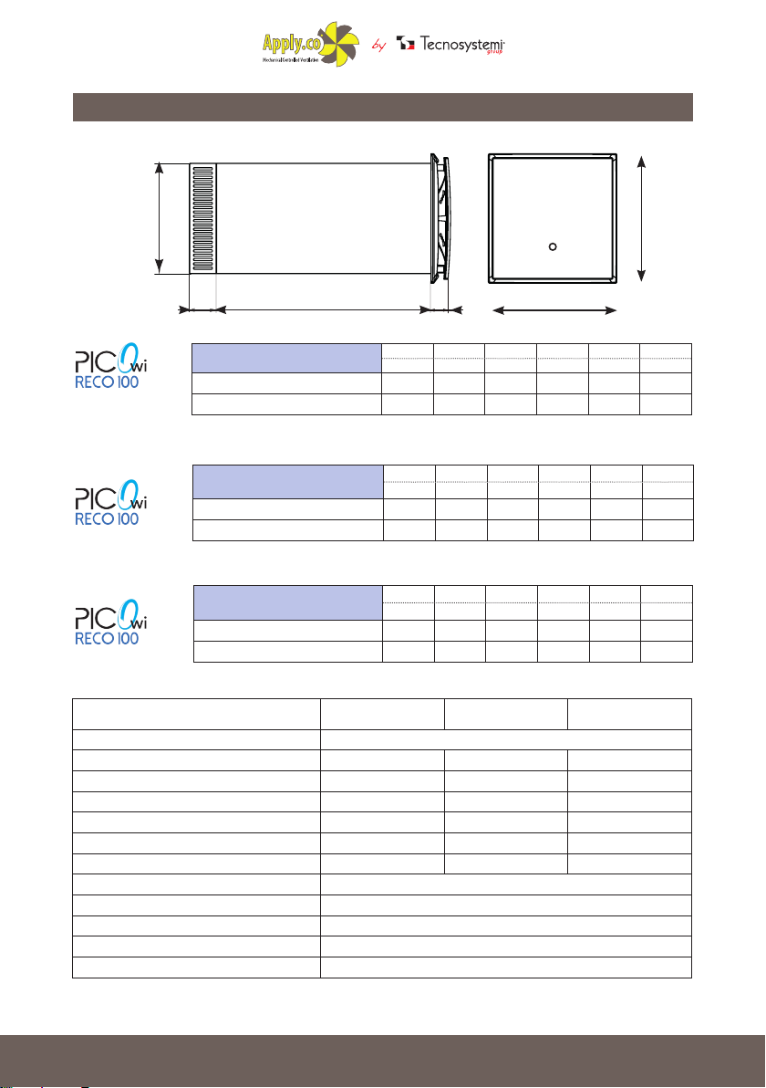
DIMENSIONS “PICO RECO 100”
05
Ø
C E
DIMENSIONS AND MODELS
ACD100019 240 240 51 204 500 35
ACD100020 240 240 51 204 500 35
DIMENSIONS AND MODELS
ACD100021 240 240 51 204 500 35
C
-
- -
SPEED MIN. 1 MED. 2 MAX. 3
SUPPLY VOLTAGE 230 Vac
POWER (W) 6,6 7,7 8,4
MAXIMUM CURRENT CONSUMED (mA) 550 640 700
MAXIMUM AIR FLOW RATE (m³/h) 70 81 91
RPM (min-1) 3395 4070 4500
SOUND PRESSURE AT 1m (dB(A) 46 48 50
SOUND PRESSURE AT 3 m (dB(A) 43 46 47
MAXIMUM AIR TEMPERATURE (°C) DA -10 °C A +50°C
REGENERATOR EFFICIENCY ≤95%
HEAT EXCHANGE FILL MEDIA POLYESTER
TUBE DIMENSIONS (mm) Ø 204
PROTECTION IP 24
ACD100022 240 240 51 204 500 35
DIMENSIONS AND MODELS
ACD100023 240 240 51 204 500 35
C CO2
ACD100024 240 240 51 204 500 35
F
A B C Ø E F
(mm) (mm) (mm) (mm) (mm) (mm)
B C Ø E F
A
(mm) (mm) (mm) (mm) (mm)
(mm)
A B C Ø E F
(mm) (mm) (mm) (mm) (mm) (mm)
A
B
Accessories for
Air Conditioning
Air Curtains and
Accessories
Multi - Zone
Air Control System
OPERATION OF RECOVERY UNITS
06
MODEL “PICO HP2” AND MODEL “PICO RECO 100”
The recovery unit consists of a xed length circular air duct, ventilation unit and external grille.
The two motors, two lters and the exchanger are inside the duct.
The lters are protected in order to purify the supply air and to prevent foreign objects
entering the exchanger and the fans.
The recovery unit generates a visual alarm (red LED indicator) as a reminder to clean or replace
the lter every 1,500 operating hours.
The ceramic exchanger (for the “PICO HP2” models) uses the thermal energy of the intake air in
order to heat the intake air ow.
For the “PICO RECO 100” model, the ll media is made of polyester.
The exchanger is tted with a draw cord on the inside to make it easier to extract (for the “PICO
HP2” models) and special clip for the “PICO RECO 100” model.
The ventilation unit must be installed on the inside part of the wall.
The external grille must be installed on the external part of the wall in order to prevent
water and other objects from entering the recovery unit.
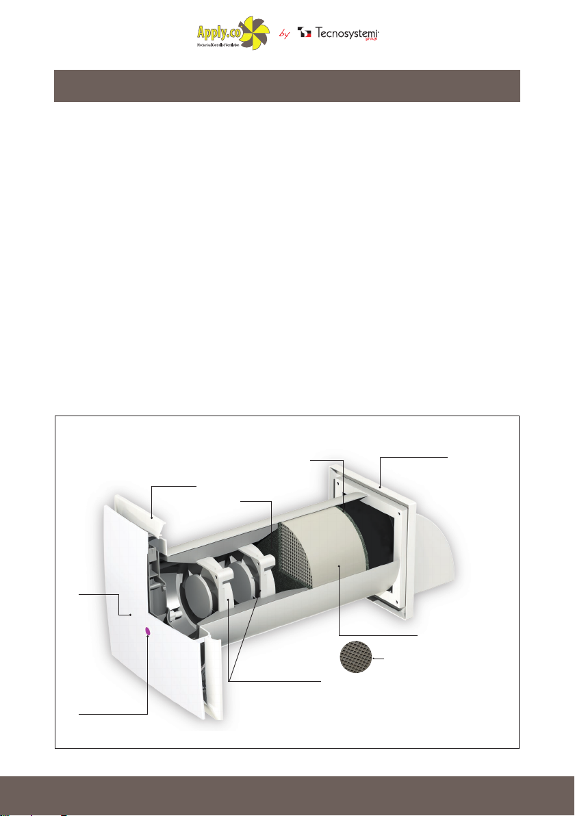
CONSTRUCTION DETAIL OF MODEL
“PICO HP2”
ATTRACTIVE
FRONT PANEL
LED INDICATOR
FUNCTION
SETTING
EXTRASLIM
GRILLE
FILTER 1
3-SPEED MOTOR
FILTER 2
HEAT EXCHANGER
EXTERNAL GRILLE
SPECIAL CERAMIC
FILL MEDIA
Accessories for
Air Conditioning
Air Curtains and
Accessories
Multi - Zone
Air Control System
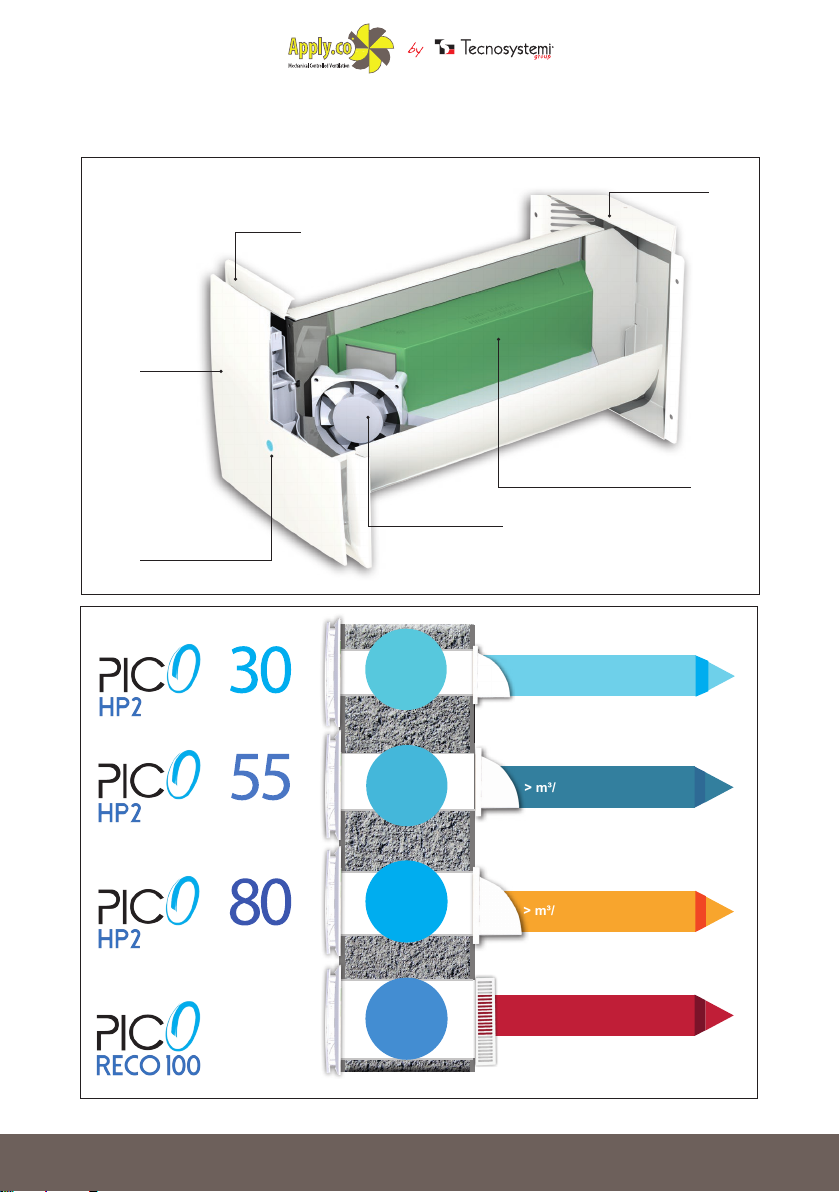
CONSTRUCTION DETAIL OF MODEL
07
“PICO RECO 100”
EXTRASLIM
GRILLE
ATTRACTIVE
FRONT PANEL
EXTERNAL GRILLE
HIGH-EFFICIENCY CROSS-FLOW
HEAT EXCHANGER
LED INDICATOR
FUNCTION SETTING
100
3-SPEED MOTOR
MAX
POWER
1,4 W
MAX
POWER
2,3 W
MAX
POWER
3,6 W
MAX
POWER
8,4 W
> m³/h 32
> m³/h 50
> m³/h 80
> m³/h 93
Ø HOLE 103 mm
Ø HOLE 128 mm
Ø HOLE 153 mm
Ø HOLE 204 mm
Accessories for
Air Conditioning
Air Curtains and
Accessories
Multi - Zone
Air Control System
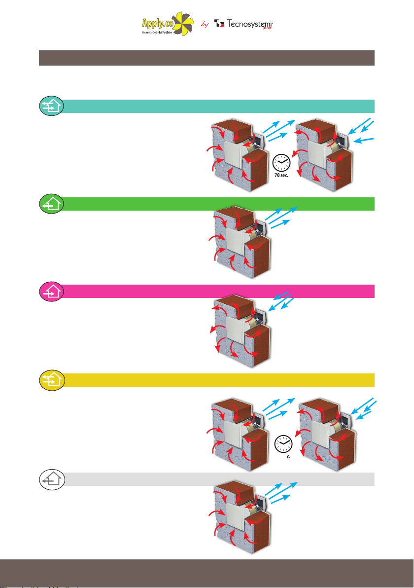
OPERATING MODES
08
N.B. Every operation mode of the PICO corresponds to a different colour
of the LED on the front cover.
REGENERATOR (LED: light blue)
THE DEVICE WORKS FOR 70 SECONDS IN
EXTRACTION MODE AND 70 SECONDS IN
AERATION MODE, WITH THE OPTION TO
REGULATE THE THREE SPEEDS. IN THE CASE
OF THE RECOVERY UNIT MODEL PICO RECO
100. THE FANS OPERATE SIMULTANEOUSLY.
(EXTRACTION AND AERATION)
70 sec.
EXTRACTION (LED: green)
THE DEVICE WORKS IN INTERNAL AIR
EXTRACTION MODE ONLY, WITH THE OPTION TO
REGULATE THE THREE SPEEDS.
AERATION (LED: purple)
THE DEVICE WORKS IN AERATION MODE
ONLY, TAKING IN AIR FROM OUTSIDE AND
INTRODUCING IT INTO THE ROOM. OPTION TO
REGULATE THE THREE SPEEDS PROVIDED.
AUTO1 (LED: yellow)
AUTO1
THE DEVICE IS ON STANDBY.
WHEN THE AIR IN THE ROOM EXCEEDS
THE HUMIDITY LEVEL, THAT CAN BE SET AT
40%, 50% OR 60%, THE DEVICE GOES ONTO
RECOVERY MODE UNTIL THE HUMIDITY
RECOVERS ACCORDING TO THE SET VALUE.
AUTO2 (LED: white)
AUTO2
THE DEVICE IS ON STANDBY. WHEN THE AIR
IN THE ROOM EXCEEDS THE HUMIDITY LEVEL,
THAT CAN BE SET AT 40%, 50% OR 60%, THE
DEVICE GOES ONTO EXTRACTION ONLY
MODE UNTIL THE HUMIDITY LEVEL RECOVERS
ACCORDING TO THE SET VALUE.
70 sec.

Accessories for
Air Conditioning
Air Curtains and
Accessories
Multi - Zone
Air Control System
AUTO3 - SUMMER COMFORT (LED: orange)
09
AUTO3
THE SYSTEM IS ON STANDBY. IF THE EXTERNAL
TEMPERATURE IS LOWER THAN THE INTERNAL
ONE, THE HEAT RECOVERY UNIT GOES ONTO
HIGH-SPEED INTAKE. WHEN THE TEMPERATURE
RECOVERS ITS VALUE THE UNIT GOES BACK
ONTO STANDBY.
AUTO4 - WINTER COMFORT (LED: pink)
AUTO4
THE SYSTEM IS ON STANDBY. IF THE
EXTERNAL TEMPERATURE IS HIGHER THAN
THE INTERNAL ONE, THE HEAT RECOVERY UNIT
GOES ONTO HIGH-SPEED INTAKE. WHEN THE
TEMPERATURE RECOVERS ITS VALUE THE UNIT
GOES BACK ONTO STANDBY.
AUTO5 (LED: blue)
AUTO5
THE SYSTEM IS ON STANDBY. WHEN THE CO2
THRESHOLD IS EXCEEDED THE HEAT RECOVERY
UNIT GOES ONTO HIGH-SPEED RECOVERY.
WHEN THE CO2 VALUE RECOVERS THE UNIT
GOES BACK ONTO STANDBY.
70 sec.
AUTO6 (LED: dark blue)
AUTO6
THE SYSTEM IS ON STANDBY. WHEN THE CO2
THRESHOLD IS EXCEEDED THE HEAT RECOVERY
UNIT GOES ONTO HIGH-SPEED OUTPUT. WHEN
THE CO2 VALUE RECOVERS THE UNIT GOES
BACK ONTO STANDBY.
FILTER MAINTENANCE
THE RED FLASHING LED INDICATES THE NEED TO PERFORM THE MAINTENANCE OF FILTERS AND
THE HEAT EXCHANGER.
SETTING THE HUMIDITY VALUE
WHEN THE BLUE LED TURNS ON, IT INDICATES THE ACCESS TO THE HUMIDITY VALUE SETTINGS
MODE. IT IS POSSIBLE TO SET THE HUMIDITY THRESHOLD TO THREE DIFFERENT VALUES 40%, 50%
O 60%
 Loading...