

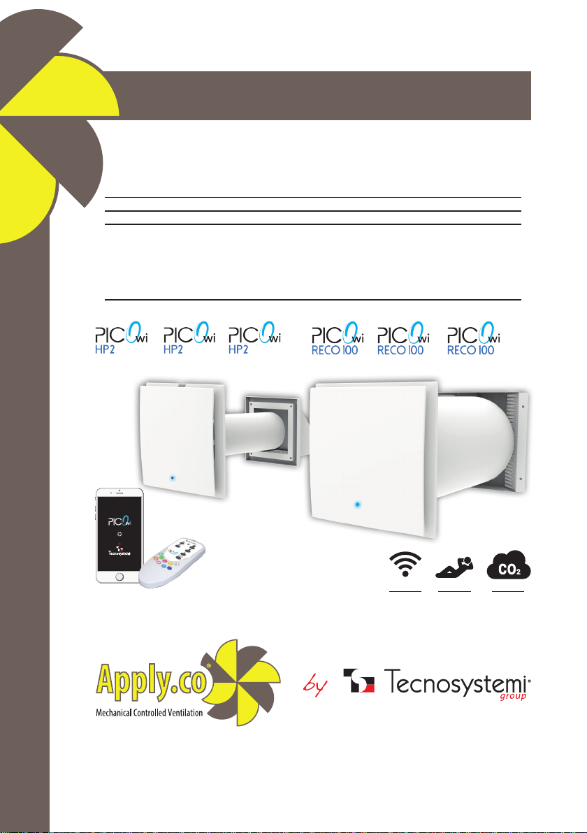
USER MANUAL
Accessories for
Air Conditioning
Air Curtains and
Accessories
Multi - Zone
Air Control System
01
"PICO WI HP2" - WALL-MOUNTED, STATIC INTAKE /
EXTRACTOR FAN WITH HEAT RECOVERY, EQUIPPED WITH EXTERNAL
POWER SUPPLY OR WITH BUILT-IN POWER SUPPLY
ACD100001 - ACD100002 - ACD100003 - ACD100004 - ACD100005 - ACD100006
ACD100007 - ACD100008 - ACD100009 - ACD100010 - ACD100011 - ACD100012
ACD100013 - ACD100014 - ACD100015 - ACD100016 - ACD100017 - ACD100018
"PICO WI RECO 100" - WALL-MOUNTED CROSS FLOW STATIC INTAKE
EXTRACTOR FAN WITH HEAT RECOVERY EQUIPPED WITH EXTERNAL
POWER SUPPLY OR WITH BUILT-IN POWER SUPPLY
ACD100019 - ACD100020 - ACD100021 - ACD100022 - ACD100023 - ACD100024
C
-
C CO2
- -
C CO2
C
-
WI-FI COMFORT CO2
- -
Accessories for
Air Conditioning
Air Curtains and
Accessories
Multi - Zone
Air Control System
INTRODUCTION
02
This manual includes the technical description, operation, installation and assembly instructions,
technical data for the intake extractor unit with energy regeneration “PICO HP2”, “PICO RECO
100”, hereinafter referred to as recovery unit.
SAFETY REQUIREMENTS
Read the user manual carefully before use and installation of heat reversible recovery unit with
individual chamber with energy regeneration.
The installation and the operation of the recovery unit must be carried out in compliance with the
user manual, as well as with applicable legislations, local and national laws and technical and
electrical regulations. The warnings, contained in the user manual, should be heeded, as they
contain vital information for personal safety.
Failure to follow the safety rules can result in damage to the recovery unit. Read this
manual carefully and keep it for as long as the recovery unit is used.
Legend of symbols used in the manual:
WARNING
PROHIBITION
USE OF THE RECOVERY UNIT
The recovery unit was designed to ensure the air exchange in apartments, holiday farms, hotels,
bars and, in general, domestic and public places.
The recovery unit is tted with a ceramic exchanger which allows the air recirculation thanks to
the energy regeneration with the heat from the intake air.
The recovery unit was designed to be installed in premises on walls with a thickness between 310 mm
and 500 mm (optional tube L=1,500 mm), for the “Pico Reco 100”, the minimum thickness is 370 mm.
The recovery unit was tested for continuous operation connected always to be mains supply.
The transported air must not contain ammable or explosive mixtures, chemical substance
vapours, large dust particles, soot and oil particles, dangerous substances, brous
materials, pathogenic agents or other harmful substances.
THE RECOVERY UNIT WAS NOT DESIGNED FOR USE BY CHILDREN, PERSONS WITH
PHYSICAL OR MENTAL DISABILITIES, PERSONS WITH SENSORY DISABILITIES, OR
PERSONS WITHOUT ADEQUATE QUALIFICATIONS.
THE INSTALLATION AND CONNECTION OPERATIONS CAN BE PERFORMED ONLY BY
QUALIFIED PERSONNEL AFTER FOLLOWING THE ADEQUATE SAFETY TRAINING.
UNATTENDED CHILDREN SHOULD NOT BE ALLOWED ACCESS TO THE SITES WHERE THE
FAN IS INSTALLED.
MAIN TECHNICAL PARAMETERS
The recovery unit was designed for application within premises with a room temperature varying
from -20°C to +50°C and relative humidity of up to 80%.
Accessories for
Air Conditioning
Air Curtains and
Accessories
Multi - Zone
Air Control System
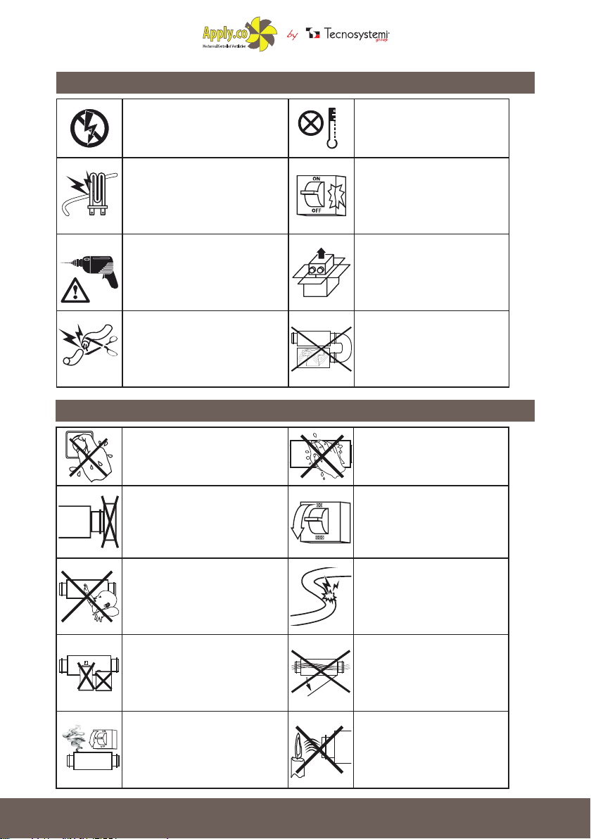
ASSEMBLY WARNINGS
03
The recovery unit must be
disconnected from the mains
supply before carrying out any
installation or repair operation.
The recovery unit must not be used
outside the temperature range,
indicated in the user manual,
or in aggressive or explosive
atmospheres.
Do not place any radiators or other
devices near the power cord of the
recovery unit.
When installing the recovery
unit, follow the specic safety
regulations for electrical
equipment.
Do not change the length of the
power cord at your own discretion.
Do not bend the power cord. Do
not damage the power cord.
SAFETY OPERATING WARNINGS
Do not touch the controls and the
remote controls with wet hands. Do
not perform maintenance operations
on the recovery unit with wet hands.
Do not block the air duct, when the
recovery unit is on.
Do not let children use the
recovery unit.
Do not use damaged equipment
or wires to connect the recovery
unit to the mains.
Carefully remove the recovery
unit from the packaging.
Use the recovery unit only
in accordance with the
manufacturer's specications.
Do not wash the recovery unit
with water. Protect the parts of
the recovery unit from water
seepage.
Disconnect the recovery
unit from the mains before
maintenance.
Do not damage the power cord
when using the recovery unit.
Do not place objects on the
power cord.
Keep explosive and ammable
products away from the recovery
unit.
In the event of unusual noises or
smoke, disconnect the recovery
unit from the wall outlet and contact
customer service.
Do not open the recovery unit
during operation.
Make sure that the air emitted
by the recovery unit is not
directed at naked ames or
candles.

Accessories for
Air Conditioning
Air Curtains and
Accessories
Multi - Zone
Air Control System
DIMENSIONS “PICO HP2”
04
Ø
F
DIMENSIONS AND MODELS
D
A B C Ø D E F
(mm) (mm) (mm) (mm) (mm) (mm) (mm)
E
ACD100001 / ACD100004 154 500 86 103 35 240 240
ACD100002 / ACD100005 186 500 101 128 35 240 240
ACD100003 / ACD100006 186 500 101 153 35 240 240
DIMENSIONS AND MODELS
C
-
ACD100007 / ACD100010 154 500 86 103 35 240 240
A B C Ø D E F
(mm) (mm) (mm) (mm) (mm) (mm) (mm)
ACD100008 / ACD100011 186 500 101 128 35 240 240
ACD100009 / ACD100012 186 500 101 153 35 240 240
A B C Ø D E F
(mm) (mm) (mm) (mm) (mm) (mm) (mm)
C CO2
- -
DIMENSIONS AND MODELS
ACD100013 / ACD100016 154 500 86 103 35 240 240
ACD100014 / ACD100017 186 500 101 128 35 240 240
ACD100015 / ACD100018 186 500 101 153 35 240 240
MODEL PICO HP2 30 WI PICO HP2 55 WI PICO HP2 80 WI
SPEED 1 2 3 1 2 3 1 2 3
SUPPLY VOLTAGE 230 Vac
POWER (W) 1,3 1,4 1,4 1,3 1,6 2,2 1,7 2,6 3,6
MAXIMUM CURRENT CONSUMED
(mA)
38 42 47 65,5 73 81 162 180 200
MAXIMUM AIR FLOW RATE (m³/h) 23 25 28 23 35 46 39 64 74
RPM (min-1) 1863 2070 2300 2106 2340 2600 2350 2610 2900
SOUND PRESSURE AT 1m (dB(A) 27 28 29 24 28 34 28 35 39
SOUND PRESSURE AT 3 m (dB(A) 25 26 27 23 26 32 26 33 37
MAXIMUM AIR TEMPERATURE (°C) FROM -10 TO +50 FROM -10 TO +50 FROM -10 TO +50
REGENERATOR EFFICIENCY ≤90% ≤90% ≤90%
HEAT EXCHANGE FILL MEDIA CERAMIC CERAMIC CERAMIC
TUBE DIMENSIONS (mm) Ø 103 Ø 128 Ø 153
PROTECTION IP 24 IP 24 IP 24
Accessories for
Air Conditioning
Air Curtains and
Accessories
Multi - Zone
Air Control System
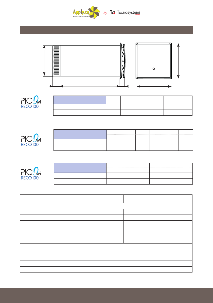
DIMENSIONS “PICO RECO 100”
05
Ø
C E
DIMENSIONS AND MODELS
ACD100019 240 240 51 204 500 35
ACD100020 240 240 51 204 500 35
DIMENSIONS AND MODELS
ACD100021 240 240 51 204 500 35
C
-
- -
SPEED MIN. 1 MED. 2 MAX. 3
SUPPLY VOLTAGE 230 Vac
POWER (W) 6,6 7,7 8,4
MAXIMUM CURRENT CONSUMED (mA) 550 640 700
MAXIMUM AIR FLOW RATE (m³/h) 70 81 91
RPM (min-1) 3395 4070 4500
SOUND PRESSURE AT 1m (dB(A) 46 48 50
SOUND PRESSURE AT 3 m (dB(A) 43 46 47
MAXIMUM AIR TEMPERATURE (°C) DA -10 °C A +50°C
REGENERATOR EFFICIENCY ≤95%
HEAT EXCHANGE FILL MEDIA POLYESTER
TUBE DIMENSIONS (mm) Ø 204
PROTECTION IP 24
ACD100022 240 240 51 204 500 35
DIMENSIONS AND MODELS
ACD100023 240 240 51 204 500 35
C CO2
ACD100024 240 240 51 204 500 35
F
A B C Ø E F
(mm) (mm) (mm) (mm) (mm) (mm)
B C Ø E F
A
(mm) (mm) (mm) (mm) (mm)
(mm)
A B C Ø E F
(mm) (mm) (mm) (mm) (mm) (mm)
A
B
Accessories for
Air Conditioning
Air Curtains and
Accessories
Multi - Zone
Air Control System
OPERATION OF RECOVERY UNITS
06
MODEL “PICO HP2” AND MODEL “PICO RECO 100”
The recovery unit consists of a xed length circular air duct, ventilation unit and external grille.
The two motors, two lters and the exchanger are inside the duct.
The lters are protected in order to purify the supply air and to prevent foreign objects
entering the exchanger and the fans.
The recovery unit generates a visual alarm (red LED indicator) as a reminder to clean or replace
the lter every 1,500 operating hours.
The ceramic exchanger (for the “PICO HP2” models) uses the thermal energy of the intake air in
order to heat the intake air ow.
For the “PICO RECO 100” model, the ll media is made of polyester.
The exchanger is tted with a draw cord on the inside to make it easier to extract (for the “PICO
HP2” models) and special clip for the “PICO RECO 100” model.
The ventilation unit must be installed on the inside part of the wall.
The external grille must be installed on the external part of the wall in order to prevent
water and other objects from entering the recovery unit.
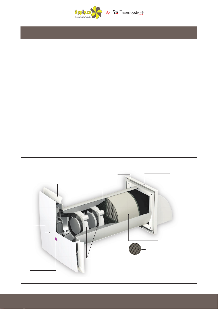
CONSTRUCTION DETAIL OF MODEL
“PICO HP2”
ATTRACTIVE
FRONT PANEL
LED INDICATOR
FUNCTION
SETTING
EXTRASLIM
GRILLE
FILTER 1
3-SPEED MOTOR
FILTER 2
HEAT EXCHANGER
EXTERNAL GRILLE
SPECIAL CERAMIC
FILL MEDIA
Accessories for
Air Conditioning
Air Curtains and
Accessories
Multi - Zone
Air Control System
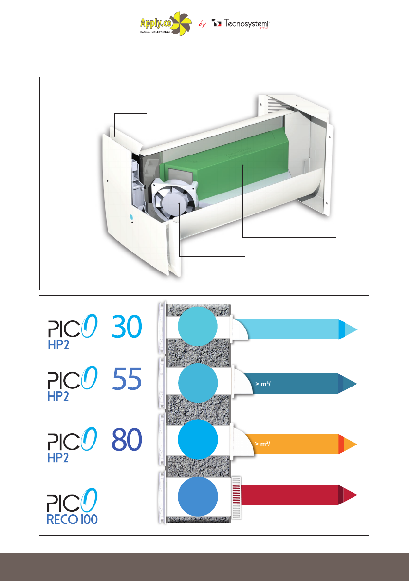
CONSTRUCTION DETAIL OF MODEL
07
“PICO RECO 100”
EXTRASLIM
GRILLE
ATTRACTIVE
FRONT PANEL
EXTERNAL GRILLE
HIGH-EFFICIENCY CROSS-FLOW
HEAT EXCHANGER
LED INDICATOR
FUNCTION SETTING
100
3-SPEED MOTOR
MAX
POWER
1,4 W
MAX
POWER
2,3 W
MAX
POWER
3,6 W
MAX
POWER
8,4 W
> m³/h 32
> m³/h 50
> m³/h 80
> m³/h 93
Ø HOLE 103 mm
Ø HOLE 128 mm
Ø HOLE 153 mm
Ø HOLE 204 mm
Accessories for
Air Conditioning
Air Curtains and
Accessories
Multi - Zone
Air Control System
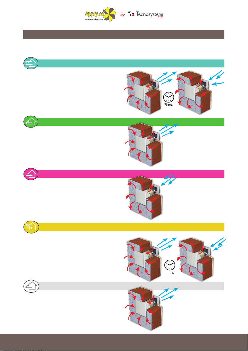
OPERATING MODES
08
N.B. Every operation mode of the PICO corresponds to a different colour
of the LED on the front cover.
REGENERATOR (LED: light blue)
THE DEVICE WORKS FOR 70 SECONDS IN
EXTRACTION MODE AND 70 SECONDS IN
AERATION MODE, WITH THE OPTION TO
REGULATE THE THREE SPEEDS. IN THE CASE
OF THE RECOVERY UNIT MODEL PICO RECO
100. THE FANS OPERATE SIMULTANEOUSLY.
(EXTRACTION AND AERATION)
70 sec.
EXTRACTION (LED: green)
THE DEVICE WORKS IN INTERNAL AIR
EXTRACTION MODE ONLY, WITH THE OPTION TO
REGULATE THE THREE SPEEDS.
AERATION (LED: purple)
THE DEVICE WORKS IN AERATION MODE
ONLY, TAKING IN AIR FROM OUTSIDE AND
INTRODUCING IT INTO THE ROOM. OPTION TO
REGULATE THE THREE SPEEDS PROVIDED.
AUTO1 (LED: yellow)
AUTO1
THE DEVICE IS ON STANDBY.
WHEN THE AIR IN THE ROOM EXCEEDS
THE HUMIDITY LEVEL, THAT CAN BE SET AT
40%, 50% OR 60%, THE DEVICE GOES ONTO
RECOVERY MODE UNTIL THE HUMIDITY
RECOVERS ACCORDING TO THE SET VALUE.
AUTO2 (LED: white)
AUTO2
THE DEVICE IS ON STANDBY. WHEN THE AIR
IN THE ROOM EXCEEDS THE HUMIDITY LEVEL,
THAT CAN BE SET AT 40%, 50% OR 60%, THE
DEVICE GOES ONTO EXTRACTION ONLY
MODE UNTIL THE HUMIDITY LEVEL RECOVERS
ACCORDING TO THE SET VALUE.
70 sec.

Accessories for
Air Conditioning
Air Curtains and
Accessories
Multi - Zone
Air Control System
AUTO3 - SUMMER COMFORT (LED: orange)
09
AUTO3
THE SYSTEM IS ON STANDBY. IF THE EXTERNAL
TEMPERATURE IS LOWER THAN THE INTERNAL
ONE, THE HEAT RECOVERY UNIT GOES ONTO
HIGH-SPEED INTAKE. WHEN THE TEMPERATURE
RECOVERS ITS VALUE THE UNIT GOES BACK
ONTO STANDBY.
AUTO4 - WINTER COMFORT (LED: pink)
AUTO4
THE SYSTEM IS ON STANDBY. IF THE
EXTERNAL TEMPERATURE IS HIGHER THAN
THE INTERNAL ONE, THE HEAT RECOVERY UNIT
GOES ONTO HIGH-SPEED INTAKE. WHEN THE
TEMPERATURE RECOVERS ITS VALUE THE UNIT
GOES BACK ONTO STANDBY.
AUTO5 (LED: blue)
AUTO5
THE SYSTEM IS ON STANDBY. WHEN THE CO2
THRESHOLD IS EXCEEDED THE HEAT RECOVERY
UNIT GOES ONTO HIGH-SPEED RECOVERY.
WHEN THE CO2 VALUE RECOVERS THE UNIT
GOES BACK ONTO STANDBY.
70 sec.
AUTO6 (LED: dark blue)
AUTO6
THE SYSTEM IS ON STANDBY. WHEN THE CO2
THRESHOLD IS EXCEEDED THE HEAT RECOVERY
UNIT GOES ONTO HIGH-SPEED OUTPUT. WHEN
THE CO2 VALUE RECOVERS THE UNIT GOES
BACK ONTO STANDBY.
FILTER MAINTENANCE
THE RED FLASHING LED INDICATES THE NEED TO PERFORM THE MAINTENANCE OF FILTERS AND
THE HEAT EXCHANGER.
SETTING THE HUMIDITY VALUE
WHEN THE BLUE LED TURNS ON, IT INDICATES THE ACCESS TO THE HUMIDITY VALUE SETTINGS
MODE. IT IS POSSIBLE TO SET THE HUMIDITY THRESHOLD TO THREE DIFFERENT VALUES 40%, 50%
O 60%

Accessories for
Air Conditioning
Air Curtains and
Accessories
Multi - Zone
Air Control System
FUNCTION
10
DESCRIPTION REGENERATOR EXTRACTION AERATION
"PICO HP2 30 WI" WITH EXTERNAL POWER SUPPLY X X X X X X X X
"PICO HP2 55 WI" WITH EXTERNAL POWER SUPPLY X X X X X X X X
"PICO HP2 80 WI" WITH EXTERNAL POWER SUPPLY X X X X X X X X
"PICO HP2 30 WI" WITH BUILT-IN POWER SUPPLY X X X X X X X X
"PICO HP2 55 WI" WITH BUILT-IN POWER SUPPLY X X
"PICO HP2 80 WI" WITH BUILT-IN POWER SUPPLY X X X X X X X X
"PICO HP2 30 WI-C COMFORT" WITH EXTERNAL POWER SUPPLY X X X X X X X X X X
"PICO HP2 55 WI-C" COMFORT" WITH EXTERNAL POWER SUPPLY X X X X X X X X X X
"PICO HP2 80 WI-C" COMFORT" WITH EXTERNAL POWER SUPPLY X X X X X X X X X X
"PICO HP2 30 WI-C" COMFORT" WITH BUILT-IN POWER SUPPLY X X X X X X X X X X
"PICO HP2 55 WI-C" COMFORT" WITH BUILT-IN POWER SUPPLY X X
"PICO HP2 80 WI-C" COMFORT" WITH BUILT-IN POWER SUPPLY X X X X X X X X X X
"PICO HP2 30 WI-C-CO2 COMFORT" WITH EXTERNAL POWER SUPPLY X X X X X X X X X X X X
"PICO HP2 55 WI-C-CO2 COMFORT" WITH EXTERNAL POWER SUPPLY X X X X X X X X X X X X
"PICO HP2 80 WI-C-CO2 COMFORT" WITH EXTERNAL POWER SUPPLY X X X X X X X X X X X X
"PICO HP2 30 WI-C-CO2 COMFORT" WITH BUILT-IN POWER SUPPLY X X X X X X X X X X X X
"PICO HP2 55 WI-C-CO2 COMFORT" WITH BUILT-IN POWER SUPPLY X X
"PICO HP2 80 WI-C-CO2 COMFORT" WITH BUILT-IN POWER SUPPLY X X X X X X X X X X X X
"PICO RECO 100 WI" WITH EXTERNAL POWER SUPPLY X X X X X X X X
"PICO RECO 100 WI-C COMFORT" WITH EXTERNAL POWER SUPPLY X X X X X X X X X X
"PICO RECO 100 WI-C-CO2" WITH EXTERNAL POWER SUPPLY X X X X X X X X X X X X
"PICO RECO 100 WI" WITH BUILT-IN POWER SUPPLY X X X X X X X X
"PICO RECO 100 WI-C COMFORT" WITH BUILT-IN POWER SUPPLY X X
"PICO RECO 100 WI-C-CO2" WITH BUILT-IN POWER SUPPLY X X X X X X X X X X X X
SETTING THE HUMIDITY VALUE
To set the value of the desired humidity (40%, 50% or 60%) proceed as follows:
• Using remote control, select AUTO 1 mode 1 (yellow LED) or AUTO 2 (white
LED).
• Press the "ON" key.
• The colour of the LED changes from yellow (or white) to blue.
• Use the keys for changing the speed of the fans to select the
desired humidity value. Key for minimum speed 40% humidity, key for
medium speed 50% humidity, key for maximum speed 60% humidity
• By selecting the desired humidity value, the colour of the LED will change from blue to
yellow (or white) and you will notice the following:
• Selected value 60% (key for maximum speed), the LED changes from blue to yellow
(or white) and you will see 3 ashes and hear an audible signal. When this operation is
completed, the yellow (or white) LED will remain xed to conrm that the humidity value

Accessories for
Air Conditioning
Air Curtains and
Accessories
Multi - Zone
Air Control System
SETTING
11
HUMIDITY VALUE
WI-FI AUTO 1 AUTO 2 AUTO 3 AUTO 4 AUTO 5 AUTO 6
INSTRUCTIONS
FILTER
MAINTENANCE
X X X X X X
X X X X X X X X
X X X X X X X X X X
X X X X X X X X
you selected has been set correctly.
• Selected value 50% (key for medium speed), the LED changes from blue to yellow
(or white) and you will see 2 ashes and hear an audible signal. When this operation is
completed, the yellow (or white) LED will remain xed to conrm that the humidity value
you selected has been set correctly.
• Selected value 40% (key for minimum speed), the LED changes from blue to yellow
(or white) and you will see 1 ash and hear an audible signal. When this operation is
completed, the yellow (or white) LED will remain xed to conrm that the humidity value
you selected has been set correctly.
N.B: The factory setting for the humidity value is 40%

Accessories for
Air Conditioning
Air Curtains and
Accessories
Multi - Zone
Air Control System
USE OF REMOTE CONTROL
12
RESET FILTER MAINTENANCE
Press and hold for 3 seconds
Humidity value
setting
Fan OFF
RECOVERY UNIT
The device works for 70 seconds in
extraction mode and 70 seconds
in aeration mode, with the option
to regulate the three speeds.
In the case of the heat exchanger
model Pico Reco 100, the fans
operate simultaneously (extraction
and aeration).
EXTRACTION
The device works in internal air
extraction mode only with the
option to regulate the three
speeds.
AUTO 3
SUMMER COMFORT MODE
The system is on standby. When
the external temperature is lower
than the internal one, the heat
recovery unit goes onto highspeed output mode. When the
temperature recovers its value the
unit goes back onto standby.
AUTO 4
WINTER COMFORT MODE
The system is on standby. When
the external temperature is
higher than the internal one, the
heat recovery unit goes onto
high-speed output mode. When
the temperature recovers its value
the unit goes back onto standby.
Fan ON
ON
OFF
MODE
AUTO2
AUTO1
AUTO3
AUTO4 AUTO5
AERATION
The device works in aeration
mode only, taking in external
air and introducing it into the
room. Option to regulate the
three speeds provided.
AUTO6
Change speed
Maximum speed
(Humidity value 60%)
Medium speed
(Humidity value 50%)
Low speed
(Humidity value 40%)
AUTO 2
The device is in standby. When the air
in the room exceeds the threshold
of settable humidity at 40%, 50%
or 60%, the device switches to
extraction only mode until the
humidity level falls within the set
values.
AUTO 1
The device is in standby. When
the air in the room exceeds the
threshold of settable humidity
at 40%, 50% or 60%, the device
switches to recovery only mode
until the humidity level falls within
the set values.
AUTO 6
The system is on standby. When
the CO2 threshold of 800 ppmv is
exceeded, the heat recovery unit
goes onto high-speed recovery
mode. When the CO2 value recovers
the unit goes back onto standby.
AUTO 5
The system is on standby. When
the Co2 threshold of 800 ppmv is
exceeded, the heat recovery unit
goes onto high-speed output.
When the Co2 value recovers the unit
goes back onto standby.
Change mode
The remote control on the picture is used for PICO HP2 / RECO100 mod. WI - C - CO2.

Accessories for
Air Conditioning
Air Curtains and
Accessories
Multi - Zone
Air Control System
USE WITH SMARTPHONE / TABLET
13
SCREENS WITH BUTTONS PRESENT FOR THE DIFFERENT MODELS
Regeneration Air
PICO WI
PICO RECO 100 WI
RECOVERY UNIT EXTRACTION AERATION
HUMIDITY / AUTO 1 HUMIDITY / AUTO 2
FILTER
MAINTENANCE
ILLUSTRATION OF COLOUR ICON OFF
RECOVERY UNIT EXTRACTION AERATION
PICO WI-C
WI-FI COMFORTWI-FI
PICO RECO 100 WI-C
RECOVERY UNIT EXTRACTION AERATION
HUMIDITY / AUTO 1 HUMIDITY / AUTO 2
FILTER
MAINTENANCE
COMFORT
ILLUSTRATION OF COLOUR ICON ON
RECOVERY UNIT EXTRACTION AERATION
PICO WI-C-CO2
WI-FI COMFORT CO2
PICO RECO 100 WI-C-C02
RECOVERY UNIT EXTRACTION AERATION
HUMIDITY / AUTO 1 HUMIDITY / AUTO 2
FILTER
COMFORT
MAINTENANCE
CO2
NOTE
These are only illustrative
screens that provide a general
panoramic view of the colours.
Multiple functions cannot be
activated simultaneously.
HUMIDITY / AUTO 1 HUMIDITY / AUTO 2
FILTER
MAINTENANCE
COMFORT
40%
50%
CO2 - PURE AIR
60%
HUMIDITY / AUTO 1 HUMIDITY / AUTO 2
FILTER
COMFORT
COMFORT COMFORT
40%
MAINTENANCE
50%
CO2 - PURE AIR
CO2 - PURE AIR CO2 - PURE AIR
60%

Accessories for
Air Conditioning
Air Curtains and
Accessories
Multi - Zone
Air Control System
CONNECTION OPERATIONS BY MEANS OF WI-FI
Regeneration Air
14
TO THE “PICO” EQUIPPED WITH RADIO MODULE
To access PICO.
It is sufcient to connect PICO to an electric source
and it will turn on (see image 1) automatically
in recovery mode.
(blue led light)
Access the smartphone conguration and
activation of the WI-FI function.
At the end of the search for active WI-FI
networks, the conrmation will be displayed at
the side.
14:11 | Gio 21 Marzo
Activate the PICO connection by means of WI-
FI, the conrmation will be displayed
at the side.
Search the IP address 192.168.1.1
using a search engine (for ex. Chrome)

Accessories for
Air Conditioning
Air Curtains and
Accessories
Multi - Zone
Air Control System
At the end of this search the main control screen
15
will be displayed.
This screen can be added to the telephone’s “home
screen.” The icon shown below will be present:
PICO RECO 100 WI-C-C02
RECOVERY UNIT EXTRACTION AERATION
Regeneration Air
Using this method it will not be necessary in the future
to search for the IP address on google to connect the
PICO.
WARNINGS FOR THE ASSEMBLY
WARNING!
THE RECOVERY UNIT SHOULD NOT BE INSTALLED IN
PLACES WHERE THE AIR DUCT MIGHT BE BLOCKED BY
BLINDS AND SHUTTERS, ETC. IN ORDER TO PREVENT
THE ACCUMULATION OR DEPOSIT OF DUST. MOREOVER,
THE BLINDS MIGHT OBSTRUCT THE NORMAL AIR FLOW IN
THE ROOM, MAKING THE OPERATION OF THE RECOVERY
UNIT INEFFICIENT.
HUMIDITY / AUTO 1 HUMIDITY / AUTO 2
FILTER
COMFORT
MAINTENANCE
CO2
WARNING!
DO NOT PLACE THE DEVICE ABOVE DELICATE FURNITURE
OR PICTURES. DO NOT PLACE THE DEVICE ABOVE OR
NEAR ROOM THERMOSTATS.
To mount the recovery unit, make a circular hole through the wall that is big enough to allow
insertion of the tube supplied for the various recovery unit models.
NOTE:
for diameters of the external tube, please refer to page 4 for the recovery units mod. “PICO HP2”
and page 5 for the recovery unit mod. “PICO RECO 100”

Accessories for
Air Conditioning
Air Curtains and
Accessories
Multi - Zone
Air Control System
MOUNTING RECOVERY UNITS “PICO HP2 / PICO RECO 100”
16
1) Install the duct in the wall, with a 1° inclination towards the outside. The air duct must
Be ush with the internal wall and should protrude from the external wall for 5 mm (only PICO
RECO 100 model).
INSIDE
OUTSIDE
1°
5 mm
Prepare a circular hole positioned as shown in the
adjacent gure
Ø 103-128-153 - 204
2) Prepare the power cable (see pic.1) taking care to route it, either from
the right or left, in the upper part of the duct in correspondence with the duct hole.
The mains can be laid out by means of a buried electrical sheath or an adequate electrical
channel which will contain the power cord.
The cord complete with plug must protrude from the wall for approximately 10 cm.
3) Insert the circular duct in the hole made in the wall. Fill the spaces between the wall and the
duct with silicone, foam or other suitable material. The air duct must be placed wired to the
internal wall.
C
B
A
LEGEND:
A: Circular wall duct
B: Wall mount fastening ring
C: Through holes for
power supply
pic.1

Accessories for
Air Conditioning
Air Curtains and
Accessories
Multi - Zone
Air Control System
4) Align the ring to the wall with the air duct (see pic. 2)
17
pic.2
Wall ring
Air duct
5) Fix the ring making four holes in the wall and using the four 4x30 screws and the four
dowels included in the supply. (see pic. 3)
pic.3
6) Insert the elements consisting of the ceramic exchanger and the lters (in the case of mod.
“PICO HP2”) and the ll media in polyester and the fans in the case of the recovery unit “PICO
RECO 100”.
PICO WI RECO 100
PICO WI HP2
7) Attach the fan unit to the wall ring

Accessories for
Air Conditioning
Air Curtains and
Accessories
Multi - Zone
Air Control System
ASSEMBLY OF THE RECOVERY UNIT INTAKE GRILLE
18
1 Remove the external grille in order to gain access to the xing holes..
Remove the upper part of the external ventilation grille. (see pic. 1)
MODEL
DIMENSIONS (mm)
B H L L1 L2 DIAMETER (D)
PICO WI HP2 30 154 110 15 45 87 100 1,2
PICO WI HP2 55 186 142 15 45 101 125 1,2
PICO WI HP2 80 186 142 15 50 101 150 1,2
pic.1 pic.2
2 Insert the wall plugs provided in the holes.
Grey front part
External grille mounted
Grey back part
pic.1

Accessories for
Air Conditioning
Air Curtains and
Accessories
Multi - Zone
Air Control System
3 Mark the xing holes for the external ventilation grille and drill.
19
For the sake of convenience, use the back part of the grille.(see pic.2)
pic.2
4 Fix the back part of the grille to the wall with 4x30 screws included. (see pic. 3)
pic.3
5 Assemble the upper part of the grille. (see pic. 4)
pic.4

Accessories for
Air Conditioning
Air Curtains and
Accessories
Multi - Zone
Air Control System
ASSEMBLY OF THE INTAKE GRILLE
20
RECOVERY UNITS MODEL “PICO RECO 100”
1 Mark the xing holes for the external ventilation grille and drill, inserting
the wall plugs provided.
2 Fix the rear part of the grille to the wall with the 4x30 included (see pic.5), making sure
the partition for the 2 air ows is ush with the inside of the grille.
pic.5

Accessories for
Air Conditioning
Air Curtains and
Accessories
Multi - Zone
Air Control System
CONNECTION TO THE MAINS
21
BEFORE PERFORMING ANY ELECTRICAL ASSEMBLY OPERATION, DISCONNECT
THE RECOVERY UNIT FROM THE MAINS. CONNECT THE RECOVERY UNIT TO
A SOCKET INSTALLED CORRECTLY WITH THE GROUNDING TERMINAL. IT IS
FORBIDDEN TO PERFORM ANY MODIFICATION TO THE INTERNAL CONNECTIONS
WHICH MIGHT CAUSE THE WARRANTY TO BE VOIDED
The recovery unit is calibrated for connection to the AC mono phase mains supply 230 V / 50 Hz
by means of a 12 Vdc transformer (provided). To make the connection easier, the recovery unit
is tted with a 500 mm long pre-wired power cord.
In order to power the recovery unit, insert the phone type connector in the specic socket
marked with the word IN. (see pic. 6)
CONNECTION OF RECOVERY UNITS IN SERIES
When the recovery units are connected in series, all the connected recovery units are controlled
by the rst recovery unit and a single remote control. In order to connect the recovery units in
series, connect the exit contact press of the rst recovery unit (identied with the OUT word) to
the entry contact press of the second recovery unit (identied with the IN word)
EXTERNAL POWER SUPPLY
INCLUDED WITH PART NUMBERS
ACD100001 - ACD100002 - ACD100003
ACD100007 - ACD100008 - ACD100009
ACD100013 - ACD100014 - ACD100015
ACD100019 - ACD100021 - ACD100023
IN
OUT
pic.6
BUILT-IN POWER SUPPLY
INCLUDED FOR PART NUMBERS
ACD100004 - ACD100005 - ACD100006
ACD100010 - ACD100011 - ACD100012
ACD100016 - ACD100017 - ACD100018
ACD100020 - ACD100022 - ACD100024
Connect the second recovery unit to the third recovery unit in the same way and so on, allowing
up to 4 recovery units to be connected in series.
Connecting the recovery units in series must be performed with the devices disconnected from
the mains supply
INSTALLATION DIAGRAM FOR MAX 4 “PICO” UNITS
IN CASCADE
FOR RECOVERY UNIT
PICO WI HP2 55 - 30
POWER SUPPLY INCLUDED WITH THE UNIT
FOR RECOVERY UNIT
PICO WI HP2 80 - RECO 100
POWER SUPPLY NOT INCLUDED
5
mt
5
mt
5
mt

Accessories for
Air Conditioning
Air Curtains and
Accessories
Multi - Zone
Air Control System
MAINTENANCE
22
DISCONNECT THE FAN FROM THE MAINS SUPPLY BEFORE CARRYING
OUT MAINTENANCE.
Maintenance of the fan means regularly cleaning the surfaces of the fan from dust and cleaning
or replacing the lters.
1. Maintenance of fans (once a year).
Remove the ventilator unit by pressing
simultaneously on the two locks.
Clean the blades of the impeller. In order to remove the dust,
use a soft brush, a cloth or the vacuum cleaner.
Do not use water, abrasive detergents, solvents, sharp
objects. The blades of the impeller must be cleaned once
a year.
SPECIAL LOCK

Accessories for
Air Conditioning
Air Curtains and
Accessories
Multi - Zone
Air Control System
2. Maintenance of the regenerator and of the lter (every
23
1,500 hours).
Remove the lter in front of the regenerator.
Pull the cord of the regenerator in order to remove the
regenerator from the air duct.
Take care when extracting the regenerator to avoid
damaging it. Remove the lter behind the regenerator.
Clean the lter when it is dirty (every 1,500 hours).
When the 1,500 hour operation period ends, a red indicator
LED lights up on the fan as a reminder of the need to
replace or clean the lter. The signal is repeated until the
maintenance has been completed.
Clean the lters, let them dry and insert the dried lters in
the duct.
Extraction is allowed.
The life span of the lters is of about 3 years.
For spare lters, contact the seller.
Even regular maintenance cannot fully prevent the
accumulation of dirt on the regenerator group.
Clean the regenerator regularly to ensure high efciency
heat exchange.
Clean the regenerator with a vacuum cleaner at least once
a year.
In order to reset the operation time meter, insert the lters
and the regenerator in the fan, then keep the ON/OFF
button pressed for 5 sec. and when you hear a prolonged
sound, release it.
3. Maintenance of the external grille (once a year).
The external ventilation grille can get blocked by leaves or
other objects which prevent the unit from working properly.
Check the ventilation grille twice a year and clean it whenever
necessary.
To clean the ventilation grille, remove it, then clean the air
duct.

Accessories for
Air Conditioning
Air Curtains and
Accessories
Multi - Zone
Air Control System
TROUBLESHOOTING
24
The fan does not start
when the recovery unit is
turned on.
Possible causes Management of faults
Check that the recovery unit
No power supply.
is correctly connected to the
mains supply and connect it, if
necessary.
Turn off the recovery unit. Find
The motor is blocked, the
impeller is blocked.
the cause of the motor blockage
and unblock the fan. Clean the
blades. Restart the fan.
Switch is automatically
activated after turning on.
Overcurrent due to
a short-circuit in the
electrical circuit.
Turn off the recovery unit.
Contact customer service.
Speed set low. Set a higher speed.
Clean or replace the lter, clean
Insufcient air ow
The lter, the fan or the
exchanger are dirty.
the fan and the regenerator.
For the regenerator and lter
maintenance, please refer to
page 47.
TRANSPORTATION AND STORAGE
The recovery unit must be put in the original packaging in a ventilated area at a temperature
ranging between +10°C and +40°C.
The air must not contain potentially aggressive vapours or chemical mixtures that might cause
corrosion or compromise the integrity of the connections.
For handling, use only adequate lifting equipment, in order to prevent damage to the fan following
falls or excessive shaking. Follow the applicable regulations for transportation according to the
type of load.
The recovery unit can be transported with any means, provided that adequate protection against
atmospheric agents and mechanical damages is ensured. Avoid jolts and collisions during
transportation and handling operations.

Accessories for
Air Conditioning
Air Curtains and
Accessories
Multi - Zone
Air Control System
GARANZIA / WARRANTY
25
La garanzia ha durata di 2 anni a decorrere dalla data di consegna.
L’azienda fornitrice garantisce la qualità dei materiali impiegati e la corretta realizzazione dei
componenti. La garanzia copre difetti di materiale e di fabbricazione e si intende relativa alla
fornitura dei pezzi in sostituzione di qualsiasi componente che presenti difetti, senza che possa
venir reclamata alcuna indennità, interesse o richiesta di danni.
La garanzia non copre la sostituzione dei componenti che risultano danneggiati per:
• trasporto non idoneo;
• installazione non conforme a quanto specicato in questo manuale di installazione uso e
manutenzione;
• la non osservanza delle speciche tecniche di prodotto;
• quant’altro non riconducibile a vizi originari del materiale o di produzione a condizione che il
reclamo del cliente sia coperto dalla garanzia e noticato nei termini e modalità richiesta dal
fornitore, lo stesso si impegnerà, a sua discrezione, a sostituire o riparare ciascun prodotto o le
parti di questo che presentino vizi o difetti.
The warranty lasts 2 years from the date of delivery.
The supplier company guarantees the quality of the materials used and the correct construction of
the components. The warranty covers defects in materials and manufacturing defects and refers
to the supply of spare parts of any components featuring defects, without any compensation,
interest or claim for damages.
The warranty does not cover the replacement of components damaged due to:
• incorrect transportation;
• installation not compliant with that specied in this installation, use and maintenance manual;
• non-observance of product technical specications;
• Anything else that is not linked to original faults of the material or production provided that the
customer complaint is covered by the guarantee and a claim is made within the time limit and
in the way requested by the supplier, the same supplier will commit, at their own discretion,
to replace or repair any product or part of product showing signs of faults or defects.
SMALTIMENTO / DISPOSAL
Lo smaltimento deve avvenire in conformità alle leggi in vigore per lo smaltimento
differenziato dei riuti e/o per il riciclaggio.
The equipment must be disposed of according to the laws in force for the separate
disposal of waste and/or recycling.

NOTE
Accessories for
Air Conditioning
Air Curtains and
Accessories
Multi - Zone
Air Control System
26

NOTE
Accessories for
Air Conditioning
Air Curtains and
Accessories
Multi - Zone
Air Control System
27
 Loading...