


RC-TRS
Radio Remote Control System
User’s Manual
TECNORD
SERVOCOMANDI E REGOLAZIONE

TECNORD
Write the System Number of your Radio Remote Control
Equipment here and keep it as a reference for technical
support.
Using the radio Control is forbidden for anybody who has not read and fully understood this manual. Special
attention should be given to the safety instructions herein contained.
All reproduction rights, either through photocopies or computer means or supports, are reserved. All texts,
illustrations, and drawings are the propriety of TECNORD and their use can only be granted prior to the
formal permission of TECNORD.
The technical features of the Radio Control as described in this Manual may be subsequentely modified
without notice with the sole purpose of improving the equipment to better satisfy the user.
Changes or modifications not expressly approved by TECNORD could voice the user's authority
to operate the equipment
Author: PM
Version: 1.0
Date: 12 February 2004
Tecnord Srl
Via Decorati al Valor Militare, 3
Baggiovara
41100 Modena – Italy
e-mail: tecnord@tecnord.com
web: http://www.tecnord.com
RC-TRS User’s Manual Page 2/17

TECNORD
1 SAFETY......................................................................................................................................................................4
1.1 SAFETY OF THE RADIO CONTROL SYSTEM.............................................................................................................4
1.2 SAFETY INFORMATION.............................................................................................................................................4
1.3 AUTHORIZED OPERATORS .......................................................................................................................................4
1.4 SAFETY MEASURES TO BE TAKEN WITHIN THE WORKING AREA............................................................................4
1.5 PROTECTION DEVICES .............................................................................................................................................5
1.6 HOW TO REACT AND BEHAVE IN CASE OF AN EMERGENCY ....................................................................................5
2 RC-TRS SYSTEM’S COMPONENTS ....................................................................................................................5
2.1 RC-TRS-TX CONTROL CONFIGURATIONS ............................................................................................................6
3 INSTALLATION.......................................................................................................................................................7
3.1 RC-TRS-RX SAMPLE DRAWING..............................................................................................................................7
3.2 RC-TRS-TX SAMPLE DRAWINGS............................................................................................................................8
3.3 POSITIONING THE RECEIVER ...................................................................................................................................8
3.4 OUTSIDE ELECTRICAL CONNECTIONS .....................................................................................................................9
4 OPERATION ...........................................................................................................................................................10
4.1 THE RADIO TRANSMISSION AND SERVICING SYSTEM ............................................................................................10
4.2 USE OF BATTERIES.................................................................................................................................................10
4.3 THE BATTERY CHARGER AND RE-CHARGEABLE BATTERIES ................................................................................10
4.4 CONTROL ELEMENTS.............................................................................................................................................11
4.5 VISUAL CHECK.......................................................................................................................................................11
4.6 SAFETY CONTROL AND START-UP OF THE RADIO CONTROL ...............................................................................11
4.7 FUNCTIONS OPERATION .........................................................................................................................................12
4.8 DIAGNOSTICS..........................................................................................................................................................12
4.9 OPERATING PROBLEMS..........................................................................................................................................13
4.10 TROUBLESHOOTING TABLE..................................................................................................................................14
5 MAINTENANCE.....................................................................................................................................................15
6 DISPOSAL................................................................................................................................................................15
7 TECHNICAL DATA ...............................................................................................................................................16
7.1 TRANSMITTER (RC-TRS-TX) ...............................................................................................................................16
7.2 RECEIVER (RC-TRS-RX)......................................................................................................................................16
7.3 COMMUNICATION PROTOCOL ...............................................................................................................................17
RC-TRS User’s Manual Page 3/17

TECNORD
1 SAFETY
1.1 Safety of the Radio Control System
The Radio Control System has been equipped with electronic and mechanical safety devices. Processing
control signals sent by other transmitters is impossible as the transmission codes are totally unique for each
system.
1.2 Safety Information
The use of the Radio Control applied to any machinery allows the operator greater freedom of movement
within the working area, improved handling accuracy whilst improving both the efficiency and the safety of
the operator. However, all these benefits do require a certain attention from the operator and the staff in
charge of maintenance.
The correct and safe use of the Radio Control requires the operator to visually follow the remotecontrolled machine.
It is therefore compulsory that anyone using the transmitting unit stops the Radio Control by pushing the
Emergency stop push-button during the break times.
The maintenance staff should check that the receiver unit is not powered during the control operations,
the change of the battery or the periodic or extraordinary maintenance operations in general.
Each Radio Control should be checked at least once a year. Any repair should be made at authorized
centers or centers that Tecnord has recommended or directly at the Tecnord service and spare parts center.
Any use of no-original spare parts or tampering by non-authorized staff immediately cancels all the warranty
rights.
1.3 Authorized Operators
IMPORTANT !
Always verify the operating instructions of your machine in order to be aware of any further important
information to be observed. When placing the transmitter away during the breaks, the user must make
sure that no unauthorized people can use it by pushing the Emergency Stop push-button and locking it in a
safe place. In this way, any abusive operations by unauthorized third parties will be prevented. The user
must be able to have access to all of the operating instructions that are necessary for the smooth operation
of the machine to be controlled. The user must also read and be sure to have clearly understood each
section of this manual before using the Radio Control.
1.4 Safety Measures to be taken within the working area
The user should ensure that the working area in which the Radio Control will be used is free from any
risks for the movement or other potential safety risks. For example, the user should verify that the working
area is free from any obstacles or dangerous situations that could jeopardize the possibility of operating in
total safety.
RC-TRS User’s Manual Page 4/17

TECNORD
1.5 Protection Devices
All of Tecnord’s industrial Radio Controls have been fitted with an Emergency Stop push-button on the
control board of the transmitting unit.
Several other protection devices exist in the Radio Control system which automatically intervene
whenever:
Ø There is a radio interference in the working area that affects the frequency range of the Tecnord
Radio Remote Control;
Ø The action range of the transmitting unit is exceeded.
In the event of the above the Radio Control immediately activates the Emergency Stop, and interrupts
any outgoing signal of the receiving unit whilst maintaining, whenever possible, continuous and constant
radio contact between the transmitter and receiver.
1.6 How to react and behave in case of an Emergency
WARNING !
In any Emergency situation, immediately push the red EMERGENCY STOP Push-Button (also
called: EMERGENCY STOP PUSH). Then, follow the instructions in the machine operating
manual.
2 RC-TRS SYSTEM’S COMPONENTS
A Tecnord’s RC-TRS Remote Control System includes the following parts:
Ø TRANSMITTING UNIT (RC-TRS-TX)
Ø RECEIVING UNIT (RC-TRS-RX)
Ø SERVICE CABLE
Ø BATTERIES (INCLUDED IN THE TRANSMITTING UNIT)
Ø HARNESS
The following parts can be provided as an option:
Ø BATTERY CHARGE CABLE WITH PLUG FOR IN-VEHICLE CIGARETTES-LIGHTER
All the above mentioned parts are also available as spare parts.
RC-TRS User’s Manual Page 5/17
TECNORD
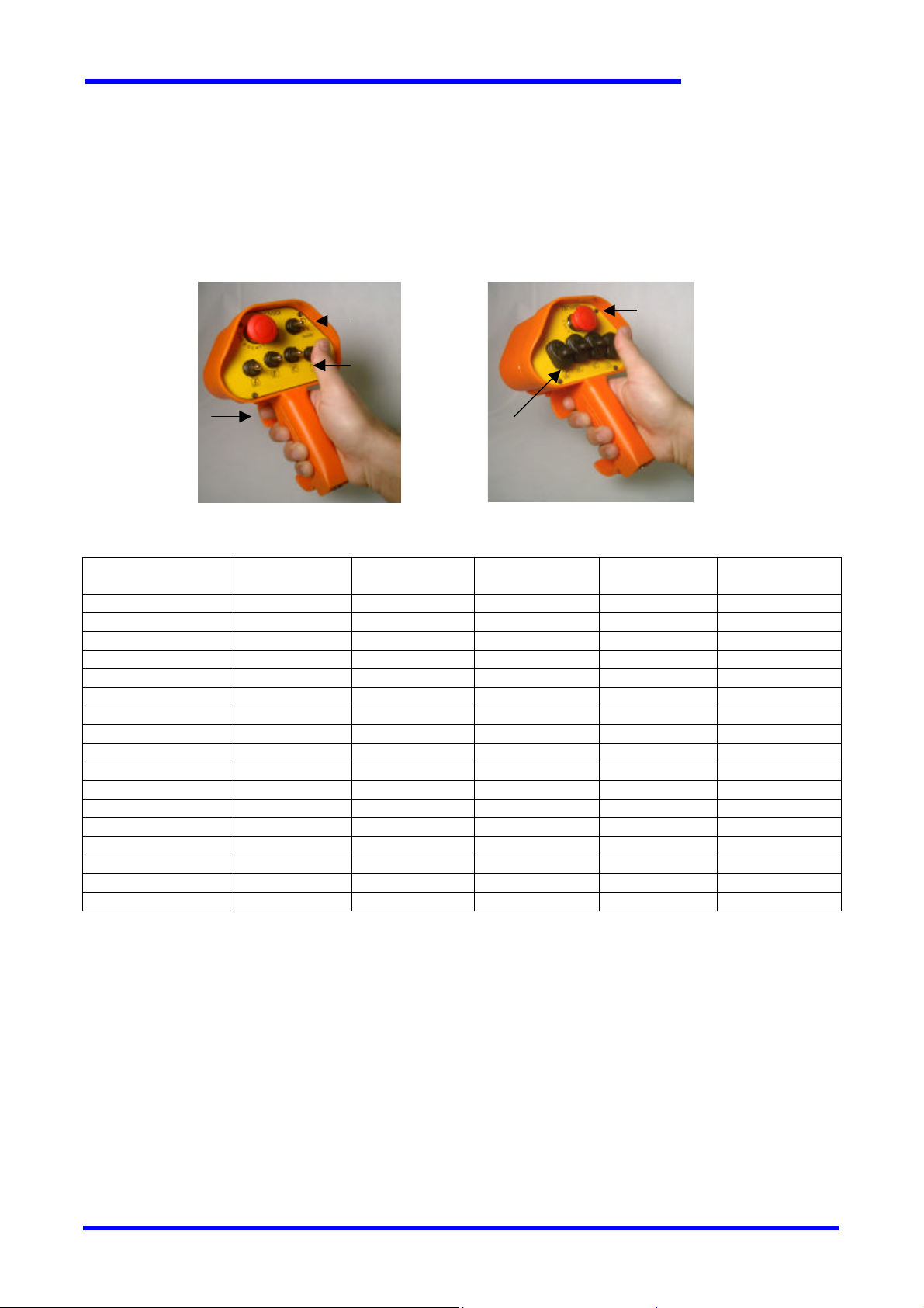
2.1 RC -TRS -TX Control Configurations
RC-TRS transmitters (RC-TRS-TX) can be provided in several control configurations, dependign on
customer’s requirements. Basically, control configurations differ in the number and type of actuators. The
figures below show the available actuators, while the next table outlines the actuators available in the
various control configurations.
Start/Stop
Toggle switch
On-Off
Toggle switches
Proportional
Trigger
PRS (Proportional
Rocker Switches)
Types of actuators available in the RC-TRS-TX transmitters.
Emergency-Stop
Pushbutton
CONTROL
CONFIGURATION
RC-TRD-4F
RC-TRD-5F
RC-TRD-6F
RC-TRD-7F
RC-TRR-4F
RC-TRR-5F
RC-TRR-6F
RC-TRR-7F
RC-TRE-4S
RC-TRE-5S
RC-TRE-6S
RC-TRM-4F
RC-TRM-5F
RC-TRM-6F
RC-TRM-4S
RC-TRM-5S
RC-TRM-6S
On-Off switches Start/Stop
switch
4 No No - Yes
5 No No - Yes
6 No No - Yes
7 No No - Yes
4 No Yes - Yes
5 No Yes - Yes
6 No Yes - Yes
7 No Yes - Yes
4 Yes Yes - Yes
5 Yes Yes - Yes
6 Yes Yes - Yes
4 No No 4 Yes
5 No No 5 Yes
6 No No 6 Yes
4 Yes No 4 Yes
5 Yes No 5 Yes
6 Yes No 6 Yes
Proportional
trigger
Housing and panel colours, as well as the panel printouts, are customizable.
PRS Emergency-Stop
RC-TRS User’s Manual Page 6/17

TECNORD
3 INSTALLATION
WARNING !
Ø Only a qualified and specialized technician should install the receiver of a radio control to
the electrical system of a machine (see item 4, Maintenance) who is acquainted with
both the electrical circuit of the machine and the radio control technical features.
Ø During the entire installation stage both the transmitter and the receiver must be turned
off.
Ø All of the regulations on the health of the staff working within the installation area,
together with any local regulations in force, and those on fire prevention must be
observed.
Ø TECNORD declines all responsibility, neither does it grant any guarantee whatsoever for
any damage caused to things or persons due to the improper or careless use of this
equipment or due to the non-observance of any regulation or that, which has been
indicated in the operating instructions.
3.1 RC -TRS -RX sample drawing
RC-TRS User’s Manual Page 7/17

3.2 RC -TRS -TX sample drawings
TECNORD
TRE control configuration
TRM control configuration
3.3 Positioning the receiver
WARNING !
When positioning the receiver, check that the outside antenna is not being screened by large
metallic surfaces.
For the Radio Control to operate smoothly, it is necessary that the receiver should be installed in such a
position as to allow the maximum reception of radio waves from the antenna. The metallic parts of the
machine to be controlled that surround the receiver create a barrier that interferes with reception
In most cases, the receiver can be housed on any side of the machine or, if necessary, for installations
on vehicles even inside the glass cabin. It is also necessary to place the receiver where it is accessible and
safe to work both for those who carry out the installation of the electrical connections and for those who will
do the future maintenance.
Make sure to keep the display visible to the user in order to ease the diagnostics of the equipment during
operations.
Should such an installation be performed on board mobile machinery or on a vehicle, then you should
attach rubber bumpers. These rubber bumpers will prevent strong vibrations from the machine to the
receiver.
RC-TRS User’s Manual Page 8/17

TECNORD
3.4 Outside electrical connections
Outside electrical connections are:
Ø Power Supply
Ø Input / Output connections
For safety reasons it is recommended to install on the controlled machine a supply disconnecting device
in order to cut off the receiver’s power supply when necessary. This supply disconnecting device should
comply with the directive EN60947-3, cat. AC-23B or DC-23B. The following requirements apply to the
supply disconnecting device:
- isolate all live conductors of the electrical equipment from the supply and have one OFF and one ON
position only, that shall clearly marked with the “0” and “1” symbols respectively
- have a visible gap or a position indicator which cannot indicate OFF until all contacts are actually open
- have an external operating handle, which shall be easily accessible to the operator, and must be located
between 0,6m and 1,9m above the servicing level. The device must be provided with means permitting it
to be locked in the “off” position.
The receiver unit (RC-TRS-RX) makes available the contacts for the insertion of a safety push-button in
series with the power supply in order to carry on a “category 0 Emergency Stop” function.
Each function that is activated on the transmitter unit (RC-TRS-TX) activates a dedicated output, or a
combination of more outputs, on the receiver unit (RC-TRS-RX), depending on the configuration of the
machine to be operated.
RC-TRS User’s Manual Page 9/17

TECNORD
4 OPERATION
4.1 The radio transmission and servicing system
Tecnord’s RC-TRS Radio Control System allows for the operating machines to be controlled in general by
means of electro-magnetic waves. It is made up of a portable transmitter unit (RC-TRS-TX) held by the
operator and of a receiver unit (RC-TRS-RX) that is usually installed on the machine to be controlled.
Each function originated from several devices or control actuators of the transmitter is transformed into a
serial command that is coded and transmitted through a high-frequency carrier. The receiver captures the
information output from the transmitter, decodes the messages and sends the controls to the machine by
means of electronic power switches controlled by a microprocessor and a dedicated harness.
The information sent from the transmitter is contained in a message commonly named “telegram”. This
telegram consists of an identifier, a command field and a redundancy field for error control. The identifier, or
matching code, contains the identification elements to match the transmitter with its coupled receiver. The
command field contains all the information relevant to the commands that the machine should carry out.
The error control redundancy fields allow the receiver to discard messages that are found modified by
disturbs on the radio link.
As the matching code is unique for each TX/RX pair, each RC-TRS-TX transmitter can control through
radio waves only its coupled RC-TRS-RX receiver, which is labeled with the same System Number.
4.2 Use of Batteries
Tecnord’s Radio Control System is equipped with batteries for operating the Transmitter. Rechargeable
NiMH batteries are supplied with the RC-TRS-TX transmitter and guarantee a long operating time.
The working voltage of the transmitter is constantly controlled. Should it fall below a threshold value, the
corresponding indication is activated (green led blinking) each time the transmitter is put into operation.
From this moment, the transmitter can continue to operate, but it is recommended to recharge the batteries
as soon as possible.
Batteries are protected against short –circuit. For additional safety and ease of use, they have a
dedicated location in the RC-TRS-TX transmitter.
4.3 The battery charger and re -chargeable batteries
The RC-TRS-TX transmitter unit is equipped with a battery charger circuit; therefore it is not necessary to
remove the batteries for the charging operation, and is possible to operate the machine during the battery
charging procedure.
In order to charge the batteries, connect the RC-TRS-TX transmitter to its RC-TRS-RX receiver unit
through the service cable supplied with the equipment. As an option, a different battery charger cable can
be provided, which allows the charge to be carried out from a vehicle’s cigarette’s lighter plug.
The charging phase for a completely discharged battery can last up to three hours, and it is continously
controlled by the microprocessor. When the battery charger states that charging is complete, it automatically
disconnects, therefore avoiding overcharge phenomena that could reduce batteries life.
WARNING !
Use TECNORD original spare parts only!
If not, there is the danger of an explosion. Chemical substances that leak or parts that
detach themselves can cause irreparable damage.
RC-TRS User’s Manual Page 10/17

TECNORD
4.4 Control Elements
Tecnord manufactures a family of Industrial Radio Controls suitable for just as many applications. Further
more, Industrial Radio Controls are designed according to the specific requests of the Customer or the User.
Tecnord’s Radio Remote Control Equipment are designed as complete systems for controlling an
operating machine’s functions. Each Radio Control System can be fitted with many different control elements
according to the machine to be controlled, as well as provided with standard controls for its operation,
stopping, acoustic warning, start switch, warning led etc.
Push buttons, switches, selectors, joysticks and special control accessories complete the radio control.
Their type and number are features of each “control configuration”.
Configurations “D”, “R”, “E”: up to 6 toggle-switches with 3 positions (1 stable + 2 temporary) for
the function’s selection, 1 proportional trigger available for speed
control
Configuration “M”: up to 6 PRS (Proportional Rocker Switches) for the control of more
independent proportional functions
For a better diagnosys of the machine’s operating status, the RC-TRS-RX receiver is equipped with a
display on which is possible to make system information available.
4.5 Visual Check
WARNING !
Always check the sound condition on the transmitter before operating.
Ø Are all the safety devices in the correct position and in good condition?
Ø Are there any broken parts?
Ø Are all of the rubber protections and the actuator covers sound?
Ø Are all of the connecting plugs and cables sound?
WARNING !
Never work with a Radio Control with any of the above-mentioned damage! Always remove
any of the above-mentioned faults before starting to work!
4.6 Safety Control and Star t-up of the Radio Control
WARNING !
Important checks on some of the functions mentioned below are required for the first startup of the Radio Control!
Ø Verify that the transmitter batttery casing on the RC-TRS-TX unit also houses a rechargeable battery.
Ø Release the Emergency Stop Push Button on the RC-TRS-TX unit, if pressed.
Ø Now, your Radio Control is ready to work. Activate any function on the transmitter unit and verify
whether the machine stops when the same function is released should you release it or re-set it to
zero.
RC-TRS User’s Manual Page 11/17

TECNORD
Ø Now check that the Emergency Stop function works exactly as described by the manufacturer of the
machine by applying the following procedure:
1. Start any of the functions of the transmitter and verify that the function is activated by the
receiverand keep it running
2. Push the Emergency push button on the transmitter
3. Verify that the function carried out stops immediately and that no other functions can be
then operated from the transmitter
4. Was the safety control successful and does the Emergency Stop function work perfectly?
5. Now release all the control elements
6. Release the Emergency stop push button, your radio control is now ready to operate in total
safety
WARNING !
Should any fault or problem be noticed during the initial starting, turn the machine off
immediately. Never operate the machine unless the Emergency Stop Button functions properly.
Serious danger exists for both people and things from the non-observance of this extremely
important regulation. Any operation not conforming to this basic operating rule may lead to the
loss of both the operating permit and your warranty.
4.7 Functions operation
Two possible types of electronic control exist that can be operated from the Radio Control, the digital and
analog also named ON-OFF and Proportional respectively. The ON-OFF control determines either the
activation or deactivation of an output stage within the receiver when the transmitter activates this control.
Usually, these are commands that can be sent from push-buttons, switches, slelectors or digital joysticks.
The Proportional control is a function determining a variable output in either current or voltage in a way
which is directly proportional to the position of an analog actuator on the transmitter, be it proportional
trigger, a potentiometric joystick or a simple potentiometer. Tecnord manufactures different types of
proportional controls for several models of solenoid valves, sevo controls or other devices. The transmission
technoclogy remains unchanged, while the proportional output stage of the receiver is designed for the
different requirements of the command to be carried out.
4.8 Diagnostics
The RC-TRS Radio Control System allows diagnostics on both the RC-TRS-TX transmitter unit and the RCTRS-RX receiver unit.
The RC-TRS-TX has an internal buzzer and a green led located on the control panel. The buzzer emits a
short beep each time the transmitter is turned on activating the radio-frequency carrier. The green led
alights when any function is activated: when the “low battery” condition is entered, the green led blinks
during operations.
The RC-TRS-RX receiver is equipped with a 7-segments led display. Upon power-on, the receiver
performs a short self-diagnosis cycle, during which some indications about the current software release are
displayed.
RC-TRS User’s Manual Page 12/17

TECNORD
During the normal operating mode the receiver’s display helps in the diagnosis of the current operations
status through the following indications:
Machine ready (waiting for command)
Operation in progress (at least one function is active)
Open circuit found on an output
the display also shows the name of the output where the fault has
been found
Short circuit found on an output
the display also shows the name of the output where the fault has
been found
Example of fault diagnostics:
Open circuit on output 3B
4.9 Operating problems
Repairs and checks following failure of the Radio Control equipment must be carried out according to the
instructions below so that the system maintains all of its original features. In the event of malfunctions,
check that the machine provided with Radio Control operates properly with traditional control systems (such
as, for example, cable control, fixed panel etc.).
Verify that in the area you are opeating in with your Radio Control no other Radio equipment has started
working and is operating on the same radio frequency. Also verify that you are operating the transmitter
with its own coupled receiver.
If the outputs of the receiver unit are not energized when commands have been transmitted and the
machine cannot therefore carry out any operation, then check the state of the receiver’s power supply fuse,
check the wiring connections to find out if any of the wires is not properly connected or is out of its housing
or coupling.
The non-operation of the RC-TRS system may depend on either the transmitter or the receiver. The table
located in the following paragraph may help in the diagnosis of the most common causes of malfunction.
RC-TRS User’s Manual Page 13/17

TECNORD
4.10 Troubleshooting table
Tecnord’s Radio Control Systems implement a microprocessor technology in both the RC-TRS-TX and RCTRS-RX units. Each system is subject to a quality assurance test at the manufacturer’s plants before being
delivered to the customer. However, should a failure subsequentely occur, a swift diagnosis is possible and
hence a quick reset of the Radio Control through the technical assistance service.
FAILURE POSSIBLE CAUSE ACTION
No reaction of the RC-TRS-RX when
turned on
The RC-TRS-RX display doesn’t turn on Interruption of the receiver’s power
No reaction of the receiver to the
activation of any function on the
transmitter
Batteries are completely discharged Recharge batteries
supply
The Emergency Stop pushbutton is
pressed
(In control configurations with
proportional trigger) the proportional
trigger has been pressed before
activating the on-off function
The function is inhibited by blocks
such as limit switches etc.
Loss of radio communication
Turn the main switch on. Verify the
connections. Measure the voltage
input to the receiver unit
Release the Emergency Stop
pushbutton
Release all the actuators, activate first
the on-off actuator of the function,
and then use the proportional trigger
for speed regulation
Activate only the functions that are
allowed in the current machine’s state
Verify that you are in the Radio
Control’s operating range
Make sure that no other Radio
Controls are operating on the same
frequency in the same area
Make sure that the receiver is not
shielded by metal enclosures
Batteries short operating time Batteries damaged or at the end of life Replace batteries with Tecnord’s
original spare parts
Open or short circuit indication on one
output
Wiring problems Verify the connections the involved
output
RC-TRS User’s Manual Page 14/17

TECNORD
5 MAINTENANCE
Tecnord’s RC-TRS Radio Control System does not require any special maintenance. However, some
precautions are necessary in order to ensure that the equipment is both efficient and safe. Each radio
control must be checked at least once a year. The staff in charge of maintenance must check that the
receiver is not powered on during the checks and the inspection inside the transmitter.
Dust and other material from the working environment as well as dirt can deposit on the transmitter and
receiver units. Remove it so that the buttons, joysticks and actuators in general, including the emergency
stop push button, are always clean and therefore in good working order.
Each control unit has been designed so that all that the above causes the least amount of problems
possible to the smooth operation of the Radio Control. However, careful periodical maintenance by the user
will certainly prolong its life span.
The inner inspection of the transmitter should be carried out in a dry and dump-free place. As well as
removing all traces of dirt and drying any condensation with warm air, the checking of the connections of
the different wires and terminal boards of interconnections, as well as the dean condition of the electrical
contacts of all of the control actuators is also highly recommended.
WARNING!
In the event of the possible oxidation of the electrical contacts, never use any type of antioxidant spray or similar product. Instead, contact your service center to immediately replace
these parts. These problems can be caused by the particular environmental conditions in which
the radio control operates. Using chemical products on the actuators could cause irreparable
damage to the mechanical and electronic parts.
The duration and the capacity of the batteries depend on many elements such as the operating
temperature, the charging and discharging cycles, but basically on how often the radio control is used. It is
highly recommended to always use the battery charge until the “low battery” indication aactivates, and to
replace it at least every 2 years.
Besides the regular checks on the interconnections and the firm tightening of the terminal boards for the
output controls, it is recommended to check that the seal of the transmitter unit cover is in good condition
and that it is watertight. After 2/3 years of operation, it is suggested to check the smooth operation of the
electronic and electro-mechanical parts, their response to commands and their drop out speed. Special
layers of resin-based insulating paint and with anti-oxidant properties protect the electronic parts of the
Radio Control system; hence they do not require any maintenance. It is, however, necessary to check the
various interconnections between the different modules.
6 DISPOSAL
WARNING !
Avoid environmental pollution.
Electrical devices and their parts are dangerous waste. This specially applies to batteries and
rechargeable accumulators. Engage a specialized company for their disposal.
RC-TRS User’s Manual Page 15/17

TECNORD
7 TECHNICAL DATA
7.1 Transmitter (RC -TRS -TX)
Working frequency: from 434,050 to 434,650 MHz (European version)
from 458,525 to 459,175 (USA – Canada version)
25 kHz Channel step
Available transmission channels: 25 (European version)
11 (USA – Canada version)
RF output power: < 10 mW e.r.p.
Antenna: Fixed internal – Lambda/4
Power Supply: 4.8 VDC
Battery: Rechargeable (NiMH)
Operating time: 10 – 12 hours
Battery charger: Built-in (into the RC-TRS-TX)
battery charge through the service cable (standard supply)
Numero comandi simultanei possibili: All
Operating range: about 100 m
Diagnostics: green led
Housing material: Fiber enforced Polycarbonate
Weight: < 0,7 kg (with batteries)
Environmental protection: IP 65
7.2 Receiver (RC -TRS -RX)
Working frequency: from 434,050 to 434,650 MHz (European version)
from 458,525 to 459,175 (USA – Canada version)
25 kHz Channel step
Available receive channels: 25 (European version)
11 (USA – Canada version)
Sensitivity: - 120 dBm
Antenna: External – Lambda/4
Power Supply: From 8,5 to 30 VDC
Output power: On/Off outputs: Max 5A
Proportional outputs: Max 1A
Voltage analog outputs: 0 – 5V
Housing material: Stainless steel
Weight: < 1 kg
Environmental protection: IP 65
Response time for active emergency: < 45 ms
Response time for passive emergency: < 250 ms
RC-TRS User’s Manual Page 16/17

TECNORD
7.3 Communication Protocol
Transmission speed: 4800 bit/s
Hamming distance: ≥ 3
Matching code: 65536 combinations available
Error check: parity on each single character
vertical checksum on message
horizontal checksum on message
Auxiliary channel: RS-485, available uisng the standard supplied service cable
RC-TRS User’s Manual Page 17/17
 Loading...