


RC-DBM/PCM/NBM
Radio Remote Control Systems
TECNORD
SERVOCOMANDI E REGOLAZIONE
Use and Maintenance Manual

TECNORD
RC-DBX/PCM/NBM Use and Maintenance Manual Page 2/23
Write the System Number of your Radio Remote Control
Equipment here and keep it as a reference for technical
support.
Using the radio Control is forbidden for anybody who has not read and fully understood this manual. Special
attention should be given to the safety instructions herein contained.
All reproduction rights, either through photocopies or computer means or supports, are reserved. All texts,
illustrations, and drawings are the propriety of TECNORD and their use can only be granted prior to the
formal permission of TECNORD.
The technical features of the Radio Control as described in this Manual may be subsequentely modified
without notice with the sole purpose of improving the equipment to better satisfy the user.
Changes or modifications not expressly approved by TECNORD could voice the user's authority
to operate the equipment
Version: 7.0
Date: 24 November 2008
Tecnord Srl
Via Malavolti , 36
41100 Modena – Italy
e-mail: tecnord@tecnord.com
web: http://www.tecnord.com

TECNORD
RC-DBX/PCM/NBM Use and Maintenance Manual Page 3/23
1 SAFETY__________________________________________________________________________________ 4
1.1 Safety of the Radio Control System ________________________________________________________ 4
1.2 Safety Information _____________________________________________________________________ 4
1.3 Authorized Operators___________________________________________________________________ 4
1.4 Safety Measures to be taken within the working area_________________________________________ 4
1.5 Protection Devices______________________________________________________________________ 4
1.6 How to react and behave in case of an Emergency ___________________________________________ 4
2 RC-DBX, RC-PCM SYSTEM’S COMPONENTS _________________________________________________ 5
2.1 Transmitter Unit Control Configurations __________________________________________________ 5
3 INSTALLATION___________________________________________________________________________ 7
3.1 DBX Receiver Unit sample drawing _______________________________________________________ 7
3.2 Positioning the receiver _________________________________________________________________ 7
3.3 SHW Transmitter Unit sample drawing____________________________________________________ 7
3.4 PCJ Transmitter Unit sample drawing_____________________________________________________ 8
3.5 NBJ Transmitter Unit sample drawing ____________________________________________________ 8
3.6 Battery Charger and Serial Cable sample drawings__________________________________________ 9
3.7 Outside electrical connections ____________________________________________________________ 9
3.8 Declaration of Installation ______________________________________________________________ 10
4 OPERATION_____________________________________________________________________________ 11
4.1 The radio transmission and servicing system_______________________________________________ 11
4.2 Use of Batteries _______________________________________________________________________ 11
4.3 The battery charger and re-chargeable batteries____________________________________________ 11
4.4 Control Elements _____________________________________________________________________ 11
4.5 Visual Check _________________________________________________________________________ 12
4.6 Safety Control and Start-up of the Radio Control___________________________________________ 12
4.7 Functions operation ___________________________________________________________________ 12
4.8 PowerSave Mode and Out-of-service _____________________________________________________ 12
4.9 Diagnostics___________________________________________________________________________ 13
4.10 Operating problems ___________________________________________________________________ 13
4.11 Troubleshooting table__________________________________________________________________ 13
5 MAINTENANCE__________________________________________________________________________ 14
6 DISPOSAL _______________________________________________________________________________ 14
7 TECHNICAL DATA _______________________________________________________________________ 15
7.1 Transmitter (SHW-TX, PCJ-TX,NBJ-TX) ________________________________________________ 15
7.2 Receiver (DBX-RX) ___________________________________________________________________ 15
7.3 Communication Protocol_______________________________________________________________ 15
8 SYSTEM DIAGNOSTICS AND CONFIGURATION _____________________________________________ 16
8.1 Transmitter’s Diagnostics ______________________________________________________________ 16
8.1.1 Buzzer.......................................................................................................................................................16
8.1.2 Green Led .................................................................................................................................................16
8.2 Receiver’s Diagnostics _________________________________________________________________ 16
8.2.1 Display Menus..........................................................................................................................................16
8.2.2 Normal Display Menu ..............................................................................................................................17
8.2.3 Digital Inputs Display Menu.....................................................................................................................17
8.2.4 Current Display Menu ..............................................................................................................................18
8.2.5 Remote Control Unit Display Menu.........................................................................................................18
8.3 Calibration Menu _____________________________________________________________________ 19
8.3.1 Calibration parameters for DBR systems..................................................................................................19
8.3.2 Calibration parameters for DBM / PCM / NBM systems.........................................................................20
8.4 System Menu (for trained staff only) _____________________________________________________ 21
8.4.1 Proportional Trigger Acquisition..............................................................................................................22
8.4.2 Optional Function Setup...........................................................................................................................22
8.4.3 System Type Setup ...................................................................................................................................23
8.4.4 EV9 Mode of Operation Setup..................................................................................................................23
8.4.5 EV49 Mode of Operation Setup ...............................................................................................................23
8.4.6 Analog Voltage Output Range Setup........................................................................................................23

TECNORD
RC-DBX/PCM/NBM Use and Maintenance Manual Page 4/23
1 SAFETY
1.1 Safety of the Radio Control System
The Radio Control System has been equipped with electronic and mechanical safety devices. Processing control signals sent by
other transmitters is impossible as the transmi ss ion codes are totally unique for each system.
1.2 Safety Information
The use of the Radio Control applied to any machinery allows the operator greater freedom of movement within the working area,
improved handling accuracy whilst improving both the efficiency and the safety of the operator. However, all these benefits do require a
certain attention from the operator and the staff in charge of maintenance.
The correct and safe use of the Radio Control requires the operator to v isually follow the remote-controlled machine.
It is therefore compulsory that anyone using the transmi tting unit stops the Radio Control by pushing the Emergency stop pushbutton during the break times.
The maintenance staff should check that the receiver unit is not powered during the control opera tions, the change of the bat tery
or the periodic or extraordinary maintenance operations in general.
Each Radio Control should be checked at least once per year. Any repair should be made at authorized centers or centers that
Tecnord has recommended or directly at the Tecnord service and spare parts center. Any use of no -original spare parts or tampering by
non-authorized staff immediately cancels all the warranty rights.
1.3 Authorized Operators
IMPORTANT !
Always verify the operating instructions of your m achine in order to be aware of any further important information to be observed.
When placing the transmitter away during the breaks, the user must make sure that no unauthorized people can use it by pushing the
Emergency Stop push-button and locking it in a safe p lace. In this way, any abusive operations by unauthorized third parties will be
prevented. The user must be able to have access to all of the operating instructions that are necessar y for the smooth operation of
the machine to be controlled. The user must also read and be sure to have clearly understood each section of this manual before using
the Radio Control.
1.4 Safety Measures to be taken within the working area
The user should ensure that the working area in which the Radio Control will be used is free from any risks for the movement or
other potential safety risks. For example, the user should verify that the working area is free from any obstacles or d a ng erous situations
that could jeopardize the possibility of operating in total safety.
1.5 Protection Devices
All of Tecnord’s industrial Radio Controls have been fitted with an Emergency Stop push-button on the control board of the
transmitting unit.
Several other protection devices exist in the Ra dio Control system which automatically intervene w henever:
¾ There is a radio interference in the working area that affects the frequency range of the Tecnord Radio Remote Control;
¾ The action range of the transmitting unit is exceeded.
In the event of the above the Radio Control immediately activa tes the Emergency Stop, and interrupts any o utgoing signal of the
receiving unit whilst maintaining, whenev er possible, continuous and constant radio contac t b e tw een the transmitter and receiver.
1.6 How to react and behave in case of an Emergency
WARNING !
In any Emergency situation, immediately push the red EMERGENCY STOP Push-Butto n (also called: EMERGENCY
STOP PUSH). Then, follow the instructions in the machine operating manual.
!
! !

TECNORD
RC-DBX/PCM/NBM Use and Maintenance Manual Page 5/23
2 RC-DBX, RC-PCM SYSTEM’S COMPONENTS
A Tecnord’s RC-DBX Remote Control System includes the following parts:
¾ For RC-DBX Systems: SHW TRANSMITTER UNIT (Single Hand Wander, SHW-TX)
¾ For RC-PCM Systems: PCJ TRANSMITTER UNIT (Shoulder Strap Transmitter, PCJ-TX)
¾ DBX RECEIVER UNIT (DBX-RX) and Flying Connectors
¾ BATTERY CHARGE CABLE with plug-in for in vehicle cigarettes-lighter
¾ BATTERIES (included in the Transmitter Unit)
The following parts can be provided as an option:
¾ SERIAL CABLE (serial/battery charger cable)
¾ CUSTOMIZED HARNESS
¾ TRANSMITTER FIXING MAGNET
¾ PROGRAMMING UNIT WITH DISPLAY
All the above mentioned parts are also available as spare parts.
2.1 Transmitter Unit Control Configurations
RC-DBX transmitters (SHW-TX) can be provided in several control configurations, dependign on customer’s requirements.
Basically, control configurations differ in the numb er and type of actuators. The figures below show the available actua tors, while the
next table outlines the actuators available in the variou s control configurations.
CONTROL
CONFIGURATION
On-Off switches Start/Stop switch Proportional trigger PRS Emergency-Stop
RC-DBD 4 / 5 / 6 Yes No - Yes
RC-DBR 4 / 5 / 6 Yes Yes - Yes
RC-DBM - Yes No 4 / 5 / 6 Yes
RC-PCM transmitters (PCJ-TX) are designed for systems with multiple proportional actuators. The control configuration
therefore varies with the number of joysticks provided. Standard equipped actuators are shown in the figure below.
CONTROL
CONFIGURATION
JLP Joysticks Optional Functions Speed Selection Pushbutton Emergency-Stop
RC-PCM 4 / 5 / 6 / 7 Yes Yes Yes Yes
Proportional
Trigger
On-Off
Toggle switches
Start/Stop
Toggle switch
Connector for
battery charging and
cable communication
PRS (Proportional
Rocker Switches)
Emergency-Stop
Pushbutton
Pushbutton for
radio engagement and
auxiliary output
Toggle switches for speed selection
and auxiliar
y
functions
Connector for
battery charging and
cable communication
Emergency-Stop
Pushbutton
JLP joysticks

TECNORD
RC-DBX/PCM/NBM Use and Maintenance Manual Page 6/23
RC-NBM transmitters (NBJ-TX) are designed for systems with multiple proportional actuators. The control configuration
therefore varies with the number of joysticks provided. Standard equipped actuators are shown in the figure below.
CONTROL CONFIGURATION JLP Joysticks Optional Functions Speed Selection Pushbutton Emergency-Stop
RC-NBM 4 / 5 / 6 / 7 Yes Yes Yes Yes
Connector for
battery charging and
cable communication
JLP joysticks
Emergency-Stop
Pushbutton
Pushbutton for
radio engagement and
auxiliary output
Toggle switches for speed selection
Toggle switches for auxiliary functions

TECNORD
RC-DBX/PCM/NBM Use and Maintenance Manual Page 7/23
3 INSTALLATION
WARNING !
¾ Only a qualified and specialized technician should in stall the receiver of a radio control to the electrical system
of a machine (see par.4, Maintenance) who is acquainted with both the electrical circuit of the machine and the
radio control technical features.
¾ During the entire installation phase both the transmitter and the receiver must be turned off.
¾ All of the regulations on the health of the staff working within the installation area, together with any local
regulations in force, and those on fire prevention must be observed.
¾ TECNORD declines all responsibility, neither does it grant any guarantee whatsoever for any damage caused to
things or persons due to the improper or careless use of this equipment or due to the non-observance of any
regulation or that, which has been indicated in the operating instructions.
3.1 DBX Receiver Unit sample drawing
3.2 Positioning the receiver
WARNING !
When positioning the receiver, check that it is not being screened by large metallic surfaces.
For the Radio Control to operate smooth ly, it is necessary that the receiver shoul d be installed in such a position as to allow the
maximum reception of radio waves from the antenna. The metallic parts of the machine to be controlled that surround the receiver
create a barrier that interferes with reception
In most cases, the receiver can be housed on any sid e of the machine or, if necessary, for instal lations on vehicles even i nside the
glass cabin. It is also necessary to place the receiver where it is accessible and safe to work both for those who carry out the
installation of the electrical connections and for tho se w ho w ill do the future maintenance.
Make sure to keep the display visible to the user in order to ease the diagnostics of the equipment during operations.
Should such an installation be performed on board mobile machinery or on a vehicle, then you should attach rubber bumpers.
These rubber bumpers will prevent strong vibratio ns from the machine to the receiver.
3.3 SHW Transmitter Unit sample drawing

TECNORD
RC-DBX/PCM/NBM Use and Maintenance Manual Page 8/23
DBD/DBR control configurations DBM control configuration
3.4 PCJ Transmitter Unit sample drawing
PCM control configuration
3.5 NBJ Transmitter Unit sample drawing
NBM control configuration
TECNORD
RC-DBX/PCM/NBM Use and Maintenance Manual Page 9/23
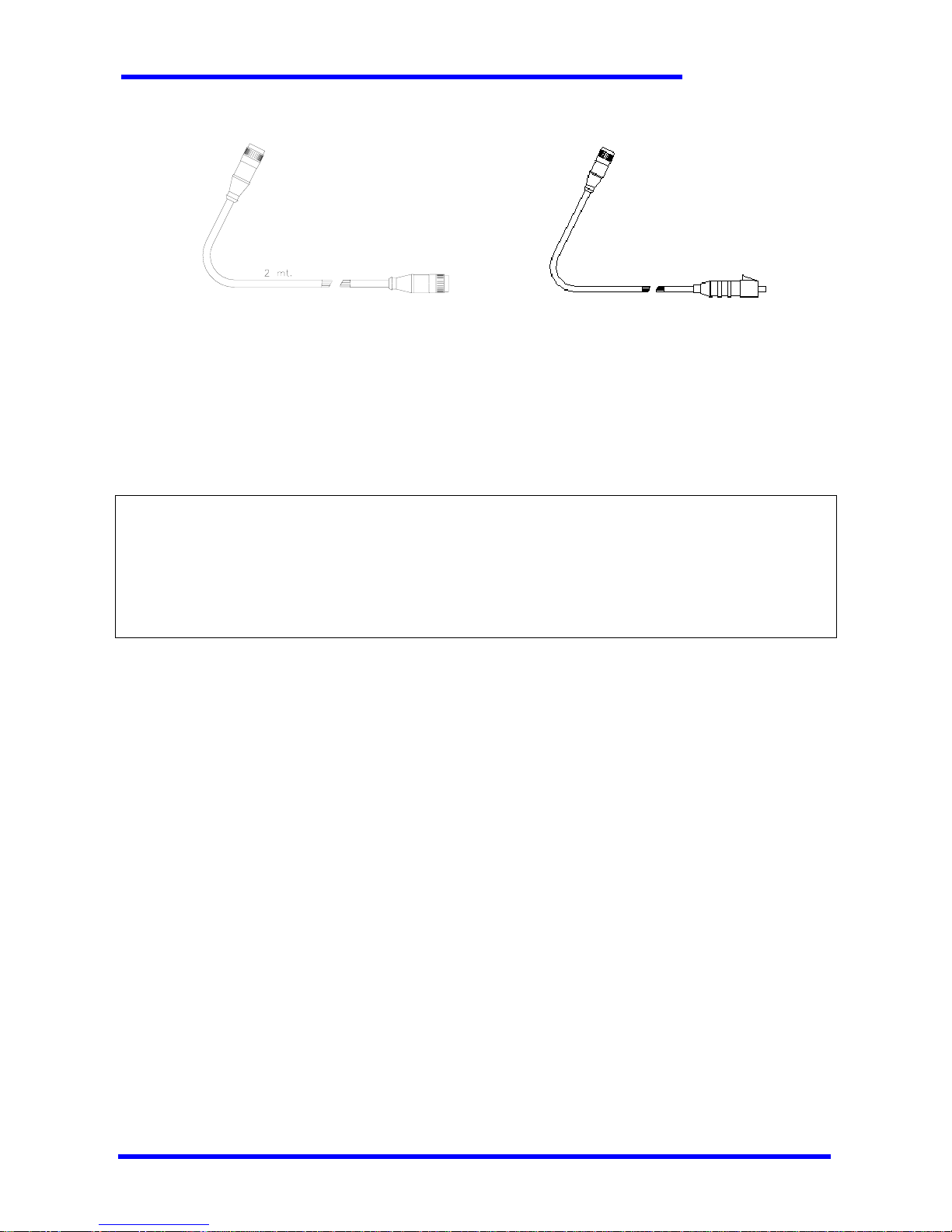
3.6 Battery Charger and Serial Cable sample drawings
SERIAL CABLE BATTERY CHARGER CABLE
3.7 Outside electrical connections
Outside electrical connections are:
¾ Power Supply
¾ Input / Output connections
For safety reasons it is recommended to i nstall on the controlled machine a supply disconnecting device in order to cut off the
receiver’s power supply when necessary. This supply disconnecting device should comply with the directive EN60947-3, cat. AC-23B or
DC-23B. The following requirements apply to the supply disconnecting device:
- isolate all live conductors of the electrical equipment from the supply and have one OFF and one ON position only, that shall clearly
marked with the “0” and “1” symbols respectively
- have a visible gap or a position indicator which cannot indicate OFF until all contacts are actually open
- have an external operating handle, which shall be easily accessible to the operator, and must be located between 0,6m and 1,9m
above the servicing level. The device must be provided with means permitting it to be locked in the “off” position.
For safety reasons, a fuse of 10A is included in the DBX-RX receiver’s box.
All the connections between the equipment and the power supply must be made with conductors having a diameter of at least
2.5mm.
Each function that is activated on the transm itter unit activates a dedicated output, or a combination of more outputs, on the
receiver unit, depending on the configuration of the machine to be operated.
M12 connector
M12 connector
M12 connector
plug

TECNORD
RC-DBX/PCM/NBM Use and Maintenance Manual Page 10/23
3.8 Declaration of Installation
WARNING !
During the installation phase it is necessary to make sure that:
¾ the radio remote control and the machine work together according to the regulation currently in force and to
the safety characteristics of the machine as supplied by the manufacturer;
¾ all the functions of the radio remote control, as well as their conformity on the equipped machine have bee n
completely checked and tested; this includes in particular the Emergency Stop function.
TECNORD is not responsible of the remore control’s installation; the installer is therefore required to issue the
operator a Declaration of Installation that must be kept together with this manual by the operator. A template for the
declaration of Installation is shown below.
DECLARATION OF REMOTE CONTROL INSTALLATION
I, the undersigned _________________________________________________________________
born in _________________________________________ State/Province_________________ on _______________________
legally responsible for the installing Company ___________________________________________________________________
with its headquarters in ____________________________________________________________________________________
DECLARE:
1 – to have installed on _______________________ on the machine of brand __________________________________
type ________________________________________ serial number ___________________________________________
at the Company _______________________________________________________________________________________
located in (street) _____________________________ (Town/City) _____________________________________________
a Radio Remote Control System branded TECNORD
type ________________________________________ model ________________________________________________
system n° ________________________________________________________________
2 – that the installation has been carried out according to the regulations currently in force for the type of machine being
equipped and that all these regulations have been observed;
3 – that the interface between the machine and the receiver is suitable and has been properly manufactured according to the
instructions provided by the manufacturer, and that all the necessary tests have been carried out.
On this day of __________________________________ in _____________________________________________________
Signature and stamp of the Installer ______________________________________
!

TECNORD
RC-DBX/PCM/NBM Use and Maintenance Manual Page 11/23
4 OPERATION
4.1 The radio transmission and servicing system
Tecnord’s RC-DBX ,RC-PCM and RC-NBM Radio C ontrol Systems allow for the operating machines to be controlled in general by
means of electro-magnetic waves. It is made up of a portable transmitter unit (SHW ,PCJ TX or NBJ-TX) held by the operator and of a
receiver unit (DBX-RX) that is usually installed on the machine to be controlled.
Each function originated from several device s or control actuators of the transmitter is t ransformed into a serial command that is
coded and transmitted through a high-frequency carrier. The receiver captures the information output from the transmitter, decodes
the messages and sends the controls to the machine by means of electronic power switches controlled by a microprocessor and a
dedicated harness.
The information sent from the transmitter is cont ained in a message commonly named “telegram”. This telegram consi sts of an
identifier, a command field and a redundancy field for error control. The identifier, or matching code, contains the identification
elements to match the transmitte r with its coup led receiver. The command field contains all the information rele vant to the commands
that the machine should carry out. The error control redundancy fi elds allow the receiver to discard messages tha t are found modified
by disturbs on the radio link.
As the matching code is unique for each TX/RX pair, each Transm itter can control through radio waves only its coupled Receiver,
which is labeled with the same System Number.
4.2 Use of Batteries
Tecnord’s Radio Control System is equipped with batteries for operating the Transmitter. Rechargeable NiMH batteries are supplied
with the Transmitter unit and guarantee a long operating time.
The working voltage of the transmitter is constantly con trolled. Should it fall below a threshold value, the correspon ding indication
is activated (green led blinking) each time the transmi tter is put into operation. From this moment, the transmit ter can continue to
operate, but it is recommended to recharge the batter ies as soon as possible. For additional power-saving, a “PowerSave” mode is
implemented (see paragraph 4.8).
Batteries are protected against short –circuit. For a d ditio nal safety and ease of use, they are located as far as possible from the rest
of the electronics in the Transmitter.
4.3 The battery charger and re-chargeable batteries
The RC-DBX-TU transmitter unit is equip ped with a battery charger circuit; therefore it i s not necess ary to remove th e batterie s for
the charging operation, and is possible to operate the machine during the battery charging procedure.
In order to charge the batteries, connect the Tra nsmitter to its DB X-RX receiver unit through the battery charger cable supplied
with the equipment. As an option, a different serial cable can be provided, which allows the charge to be carried out while operating
the machine. In order to use the serial cable option, the harness must be provided with an appropriate M12 female connec tor. The
charging phase for a completely discharged battery can last up to three hours, and it is continously controlled by the microprocessor.
When the battery charger states that charging is complete, it automati cally dis conn ects, there fore avoid ing over charge p henomena that
could reduce batteries life.
WARNING !
Use TECNORD original spare parts only! If not, there is the danger of an explosion. Chemical sub stances that leak or
parts that detach themselves can cause irreparable damage.
4.4 Control Elements
Tecnord manufactures a family of Industrial Radio Controls suitable for just as many applications. Further more, Industrial Radio
Controls are designed according to the specific requests of the Customer or the User.
Tecnord’s Radio Remote Control Equipment are designed as complete systems for controlling an operating machine’s functions.
Each Radio Control System can be fitted with many different control elements according to the machine to be controlled, as well as
provided with standard controls for its operation, stopping, acoustic warning, start switch, warning led etc.
Push buttons, switches, selectors, joysti cks and special control access ories complete the radio control. Their type and number are
features of each “control configuration”.
Configurations “D”, “R”: up to 6 toggle-switches with 3 positi ons (1 stable + 2 temporary) for the function’s
selection, 1 proportional trigger available for sp eed control in the “R” configuration
Configuration “M”: up to 6 PRS (Proportional Rocker Switches, for DBX) or 7 JL P joy sti cks (fo r PC M) for th e
control of more functions with proportional actua to rs
For a better diagnosis of the machine’s operating status, the DBX-RX receiver is equipped with a display on which is possible to
make system information available (see paragraph 8.2).
!

TECNORD
RC-DBX/PCM/NBM Use and Maintenance Manual Page 12/23
4.5 Visual Check
WARNING !
Always check the sound condition on the transmitter before operating.
¾ Are all the safety devices in the correct position and in good condition?
¾ Are there any broken parts?
¾ Are all of the rubber protections and the actuator covers sound?
¾ Are all of the connecting plugs and cables sound?
WARNING !
Never work with a Radio Control which results damaged! Always remove any of the above-mentio ned faults before
starting to work!
4.6 Safety Control and Start-up of the Radio Control
WARNING !
Important checks on some of the functions mentioned below are required for the first start-up of the Radio Control!
¾ Verify that the transmitter battery casing on the SHW-TX unit also houses a rechargeable battery and that the battery is
connected.
¾ Release the Emergency Stop Push Button on the Transmitter unit, if pressed. Releasing the Emergency Stop Push Button turns
the TX unit on. In RC-PCM or RC-NBM systems it is necessary to engage the radio control with the appropriate pushbutton.
¾ Now, your Radio Control is ready to work . Activate any function on the transmitter unit a nd verify wheth er the machine stops
when the same function is released should you release the switch or re-set the proportional actuator to zero.
¾ Now check that the Emergency Stop function works exactly as described by the manufacturer of the machine by applying the
following procedure:
1. Start any of the functions of the transmitter, verify that the function is activated by the receiver and keep it running
2. Push the Emergency push button on the transmitter
3. Verify that the function carried out stops immediately and that no other functi ons can be then operated from the
transmitter
4. Was the safety control successful and does the Emergency Stop function work perfectly?
5. Now release all the control elements
6. Release the Emergency stop push button, your radio control is now ready to operate in total safety
WARNING !
Should any fault or problem be noticed during the initial starting, turn the machine off immediately. Never operate
the machine unless the Emergency Stop Button functions properly. Serious danger exists for both people and thing s
from the non-observance of this extremely important regulation. Any operation not conforming to this basic operating
rule may lead to the loss of both the operating permit and your warranty.
4.7 Functions operation
Two possible types of electronic control exist tha t can be operated from the Radio Control, the digital and analog also named ONOFF and Proportional respectively. The ON- OFF control determines either the activatio n or deactivation of an output stage within the
receiver when the transmitter activates this control. Usually, these are commands that can be sent from push-buttons, switches,
slelectors or digital joysticks.
The Proportional control is a function determining a variable output in either current or voltage in a way which is directly
proportional to the position of an analog actuator on the transmitter, be it a prop ortional trigger, a p roportional rocker switch (PRS), a
potentiometric joystick or a simpl e potentiometer. Tecnord m anufactures different types o f proportional controls for several models of
solenoid valves, servo controls or other devices. T he transmission technoc logy remains unchanged , while the proportiona l output stage
of the receiver is designed for the different requirements of the command to be carried out.
4.8 PowerSave Mode and Out-of-service
The Transmitter is powered on when the Emergency Stop Pushbutton is released. In order to reduce power consumption a
PowerSave Mode is implemented. When the Transmitter is powered by batteries and no function is activated for five minutes the
system goes into a “PowerSave” mode: the led is switched off and the RF module is no longer active. In order to operate it is necessary
to press and then release the Emergency Stop Pushbutton.
When the Transmitter detects a low value on the batteries the led blinks indicating that battery charging is required. When the
battery level is below the threshold for sa fe operation the system goes out-of-service: the led is switched off and the RF module is no
longer active.
!
!
! !
! !

TECNORD
RC-DBX/PCM/NBM Use and Maintenance Manual Page 13/23
WARNING !
In both PowerSave and Out-of-service modes, the Transmitter is no longer powered on, even if the Emergency Stop
Pushbutton is released, due to electronic switches. Anyway, it is always a good practice to keep the Emergency Stop
Pushbutton pressed when you’re not operating in order to mechanically disconnect the batteries from the circuits.
4.9 Diagnostics
The RC-DBX , RC-PCM ,RC-NBM Radio Control Sy stems allow diagnostics on both the Transmitter units and the DBX-RX receiver
unit. The details on the system’s diagnostics can be found in chapter 8.
4.10 Operating problems
Repairs and checks following failure of the Radio Control equipment must be carried out according to the instructions below so that
the system maintains all of its original feat ures. In the event of malfunctions, check that the machine provided with R adio Control
operates properly with traditional control systems (such as, for example, cable control, fixed panel etc.).
Verify that in the area you are operating in with your Radio Control no other Radio equipment has started working and is operating
on the same radio frequency. Also verify that you are operating the transmitter with its own coupled receiver.
If the outputs of the receiver unit are not energized when comm ands have been transmitted and the machine cannot therefore
carry out any operation, then check the s tate of th e receiver’s power supply fuse , check t he wiring c onnections to find out if any of the
wires is not properly connected or is out of its housing or coupling.
The non-operation of an RC-DBX , RC-PCM , RC-NBM s ystem may depend on either the transmitter or the receiver. The table
located in the following paragraph may help in the diagnosis of the most common causes of malfunction.
4.11 Troubleshooting table
Tecnord’s Radio Control Systems implement a micr oprocessor technology in both the Transmitter and Receiver units. Each system is
subject to a quality assurance test at the manuf acturer’s plants before being delivered to the customer. However, should a failure
subsequentely occur, a swift diagnosis is possib le and hence a quick reset of the Radio Control through the technical assistance service.
FAILURE POSSIBLE CAUSE ACTION
No reaction of the Transmitter
when turned on
No battery pack is connected. Connect a Tecnord’s original battery pack
Batteries are completely discharged or
damaged
Recharge batteries or replace batteries when damaged
The Receiver’s display doesn’t
turn on
Interruption of the receiver’s power
supply
Turn the main switch on. Verify the connections and the
fuses. Measure the voltage input to the receiver unit.
Check the fuse inside the enclosure.
No reaction of the Receiver to
the activation of any function on
the transmitter
The Emergency Stop pushbutton is
pressed
Release the Emergency Stop pushbutton to turn the
Transmitter on
The radio control has not been engaged Engage the radio control using the appropriate pushbutton
The Transmitter is in PowerSave mode Press and then release the Emergency Stop pushbutton to
resume normal operating mode
The Transmitter is out of service Recharge batteries
(In control configurations with
proportional trigger) the proportional
trigger has been pressed before
activating the on-off function
Release all the actuators, activate first the on-off actuator
of the function, and then use the proportiona l trig ger for
speed regulation
The function is inhibited by blocks such
as limit switches etc.
Activate only the functions that are allowed in the current
machine’s state
Loss of radio communication Verify that you are in the Radio Control’s operating range
Make sure that no other Radio Controls are operating on
the same frequency in the same area
Make sure that the receiver is not shielded by metal
enclosures
Batteries short operating time Batteries damaged or at the end of life Replace batteries with Tecnord’s original spare parts
Open or short circuit indication
on one output
Wiring problems Verify the connections the inv olv ed output
WARNING !
In the event of malfunctions, please check the items outlined in the above table before contacting the Tec hnical
Assistance Service.
!
!

TECNORD
RC-DBX/PCM/NBM Use and Maintenance Manual Page 14/23
5 MAINTENANCE
Tecnord’s RC-DBX,RC-PCM,RC-NBM Rad io Control Systems does not require any specia l maintenance. However, some precautions
are necessary in order to ensure that the equipment is both efficient and safe. Each radio control must be checked at least once a year.
The staff in charge of maintenance must check that the receiver is not powered on during the checks and the inspection inside the
transmitter.
Dust and other material from the working environment as well as dirt can deposit on the transmitter and receiver units. Remove it
so that the buttons, joysticks and actuators in general, including the emergency stop push button, are always clean and therefore in
good working order.
Each control unit has been designed so that all that the above causes the least amount of problems possible to the smooth
operation of the Radio Control. However, careful periodical maintenance by the user will certainly prolong its life span.
The inner inspection of the transmitter should be carried out only by trained staff in a dry and dump-free place. As well as removing
all traces of dirt and drying any condensation with warm air, the checking of the connections of the different wires and terminal boards
of interconnections, as well as the dean condition of the elec tri cal contacts of all of the control actuators is also highly recommended.
WARNING!
In the event of the possible oxidation of the electrical contacts, nev er use any type of anti-oxidant spray or similar
product. Instead, contact your service center to immediately replace these parts. These problems can be cau sed by the
particular environmental conditions in which the radio control operates. Using chemical products on the actuators
could cause irreparable damage to the mechanical and electronic parts.
The duration and the capacity of the batteries depend on many elements such as the operating temperature, the charging and
discharging cycles, but basically on how often the radio control is used. It is highly recommended to always use the battery charge until
the “low battery” indication aactivates, and to repl ace it at least every 2 years.
Besides the regular checks on the interconnections and the firm tig htening of the terminal boards for the output controls, it is
recommended to check that the seal of the transmitter unit cover is in good condition and that it is watertight. After 2/3 years of
operation, it is suggested to check the smooth operation of the elec tronic and electro-mechanical parts, their response to commands
and their drop out speed. Special layers of resin-based ins ulating paint and with anti-oxidan t properties protect the electro nic parts of
the Radio Control system; hence they do not require an y maintenance. It is, however, nece ssary to check the various interco nnections
between the different modules.
6 DISPOSAL
WARNING !
Avoid environmental pollution.
Electrical devices and their parts are dangerous waste. This specially applies to batteries and rechargeable accumulators. Engage a
specialized company for their disposal.
!
!

TECNORD
RC-DBX/PCM/NBM Use and Maintenance Manual Page 15/23
7 TECHNICAL DATA
7.1 Transmitter (SHW-TX, PCJ-TX,NBJ-TX)
USA/CANADA version EUROPE version
Working frequency: 902 ÷ 928 MHz 869.7 ÷ 870 MHz
Transmission Type: FHSS (Frequency Hopping Spread Spectrum) Single Frequency FSK
RF output power: < 200 mW e.r.p. < 5 mW e.r.p
Antenna: Fixed internal
Power Supply: 4.8 VDC
Battery: Rechargeable (NiMH)
Operating time: 8 - 10 hours
Battery charger: Built-in (into the RC-DBX-TU)
battery charge through the service cable (standard supply)
Simultaneous commands available: All
Operating range: about 50 m about 30 m
Diagnostics: buzzer, green led
Housing material: Fiber enforced Polycarbonate
Weight: < 0,7 kg (with batteries)
Environmental protection: IP 65
7.2 Receiver (DBX-RX)
USA/CANADA version EUROPE version
Working frequency: 902 ÷ 928 MHz 869.7 ÷ 870 MHz
Sensitivity: - 100 dBm
Antenna: Fixed internal
Power Supply: From 8,5 to 30 VDC
Output power: On/Off outputs: Max 3.5A
Proportional outputs: Max 1.8A
Voltage analog outputs: choice between 0 – 5V, 0 – 20mA
Housing material: Thermoplastic
Connectors Deutsch
Weight: < 0.4 kg
Environmental protection: IP 65
Response time for passive
emergency:
< 250 ms
7.3 Communication Protocol
Transmission speed: 9600 bit/s
Error check: 32-bit CRC
Auxiliary channel: RS-485, available uisng the standard supplied service cable

TECNORD
RC-DBX/PCM/NBM Use and Maintenance Manual Page 16/23
8 SYSTEM DIAGNOSTICS AND CONFIGURATION
8.1 Transmitter’s Diagnostics
Diagnistic on the Transmitter unit is carried out by means of:
¾ a buzzer
¾ a green led
8.1.1 Buzzer
Indications in Radio Mode:
The buzzer provides the following indications:
¾ one short beep when the Transmitter is powered on, i.e. when the Emergency Stop Pushbutton is released;
¾ four short beeps when the Transmitter enters PowerSave mode o r goes out of service due to a low battery voltage.
Indications in Cable Mode:
The buzzer provides the following indications:
¾ one short beep when the Transmitter is powered on, i.e. when the Battery Charger Cable is connected to the unit.
8.1.2 Green Led
Indications in Radio Mode:
The led provides the following indications:
¾ led on while the Transmitter is powered on, i.e. when the Emergency Stop Pushbutton is released, and the battery level is
correct for safe operation;
¾ led continously blinking while the T ransmitter is powered on, i.e. when the Emergency Stop Pushbutton is released, and
the battery level is low;
¾ led off while the Transmitter is in PowerSave mode or out of service because of an insu fficient batt ery level, or when the
unit is powered off, i.e. when the Emergency Stop Pushbutton is pressed.
Indications in Cable Mode:
The led provides the following indications:
¾ led intermittently blinking (two blinks followed by a pause) indicates that the battery charger is active;
¾ led on indicates that the Transm itter is powered on (i.e. the cable hase been connected) and is ready for operation;
during battery charging , it indicates that a function is active;
¾ led off indicates that the Transmitter is not charging the battery and the emergency pushbutton is pressed.
Note
:
When the cable is connected the Transmitter perform s some batt ery che cks for abo ut 3 second s. Aft er that tim e batt ery charging is
automatically started when no faults are detected.
8.2 Receiver’s Diagnostics
8.2.1 Display Menus
The three-digits, seven segments display shows the operating state of the DBX-RX Receiver; the visualization is organized in six
menus:
¾ Normal Display Menu
¾ Calibration Menu
¾ System Menu
¾ Digital Inputs Display Menu (only in RC-DBD/DBR systems)
¾ Current Display Menu (only in RC-DBD/DBR systems)
¾ Remote Control Unit Display Menu (only in RC-DBD/ D BR systems)
The Normal Display Menu is the menu for the normal operating mode and is selected by default when the Receiver is being
powered on; from this menu it is possible to access any other menu (with the exception of the System Menu).
Only the two Pushbuttons integrated in the re ceiver’s electronics allow to access the System Menu; it is recommen ded that the
System Menu be accessed only by personnel trained for the Technical Assistance Service.

TECNORD
RC-DBX/PCM/NBM Use and Maintenance Manual Page 17/23
8.2.2 Normal Display Menu
This is the menu for the normal operating mod e, and is selected by default when the Receiver is powered on. The following
indications are displayed:
Normal operation:
No active operation
(waiting for RF signal)
No active operation
(RF signal detected)
(waiting for engagement)
No active operation
(RF signal detected)
(radio engaged)
_OP Operation in progress
Alarm indications (only in DBD / DBR systems):
Oxx Open circu it dete cted on valve xx when trying to
start a movement (see the table with all the alarm codes)
Example: open circuit
alarm on valve 3B:
Cxx Short circuit detected on valve xx when trying to
start a movement (see the table with all the alarm codes).
Example: short circuit
alarm on valve 1A:
The following table shows all the displayed alarm codes.
Display Alarm type Valve with active alarm Display Alarm type Valve with active alarm
O1A open cir cu it EV on/off 1A C1A short circuit EV on/off 1A
O1b open circuit EV on/off 1b C1b short circuit EV on/off 1b
O2A open cir cu it EV on/off 2A C2A short circuit EV on/off 2A
O2b open circuit EV on/off 2b C2b short circuit EV on/off 2b
O3A open cir cu it EV on/off 3A C3A short circuit EV on/off 3A
O3b open circuit EV on/off 3b C3b short circuit EV on/off 3b
O4A open cir cu it EV on/off 4A C4A short circuit EV on/off 4A
O4b open circuit EV on/off 4b C4b short circuit EV on/off 4b
O5A open cir cu it EV on/off 5A C5A short circuit EV on/off 5A
O5b open circuit EV on/off 5b C5b short circuit EV on/off 5b
O_r open circuit VR (proportional) C_r short circuit VR (proportional)
8.2.3 Digital Inputs Display Menu
This paragraph is applicable only to systems that i m plement digital inputs (e.g. limit switches).
This menu is accessed from the Norm al Display Menu with the following procedure: push the proportional trigger to its maximum
level, then activate the 1A (first actuator from the left towards up) and 3B (third selector from the left towards down) functions
simultaneously for at least 5 seconds.
In this menu the states of the IN0 and IN1 inputs are displayed cyclically, with a 2.5s interval; each digital input can be in one of
the following states:
O open
C closed
Example: indication of the state “IN1 open”
Example: indication of the state “IN0 closed”

TECNORD
RC-DBX/PCM/NBM Use and Maintenance Manual Page 18/23
The following table shows all the displayed codes:
Displayed code for Microswitch open Displayed code for Microswitch closed Displayed Digital Input
0_O 0_C IN0
1_O 1_C IN1
When no operation is activated the R eceiver autom atically switc hes to the N ormal Display Menu after 6 0s, otherwis e a new poweron is required in order to get out of this menu.
8.2.4 Current Display Menu
This paragraph is applicable only to systems that implement a proportional trigger.
This menu is accessed from the Norm al Display Menu with the following procedure: push the proportional trigger to its maximum
level, then activate the 1A (first actuator from the lef t towards up) and 4B (fourth actuator from the left towards d own) movements
simultaneously for at least 5 seconds.
In this menu, when no operation is active the indication “Cur” is displayed. When a movement is active the value of the current (in
mA) that is set for the proportional valve is displayed.
Example: indication without any active movement
Example: indication with an active movement and with 523mA set
for the proportional valve
When no operation is activated the R eceiver autom atically switc hes to the N ormal Display Menu after 6 0s, otherwis e a new poweron is required in order to get out of this menu.
8.2.5 Remote Control Unit Display Menu
This menu is accessed from the Normal Display Menu with the following procedure: push the proportional trigger to its maximum
level, then activate the 1A (first actua tor from the left towards up) and 2B (second actuator from the left towards d own) movements
simultaneously for at least 5 seconds.
In this menu, when no operation is ac tive the indication “_ _ _” is displayed. Whe n a movement is active the state of the contact
that activated the movement in the SHW-TX Transmitter is displayed. For each of the contacts the following state is displayed:
C closed
In case of a multiple command (two or more movements activated simultaneously) only the state of one of the active comma nds is
displayed, following an internal priority scheme.
Example: indication without any active function
Example: indication when the contact 1A is closed on the SHW-TX
The following table shows all the displayed codes:
Display Displayed Status
C1A closed contact 1A
C1b closed contact 1B
C2A closed contact 2A
C2b closed contact 2B
C3A closed contact 3A
C3b closed contact 3B
C4A closed contact 4A
C4b closed contact 4B
C5A closed contact 5A
C5b closed contact 5B
CEA closed Engine Start
CEb closed Rngine Stop
When no operation is activated the R eceiver autom atically switc hes to the N ormal Display Menu after 6 0s, otherwis e a new poweron is required in order to get out of this menu.
TECNORD
RC-DBX/PCM/NBM Use and Maintenance Manual Page 19/23
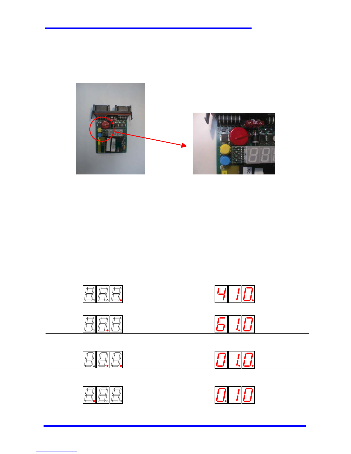
8.3 Calibration Menu
This paragraph is applicable only to systems that implemen t a proportional current output . The calibration of the p arameters of the
proportional output is carried out using the tw o Pushbuttons (Blue Key and Yellow Key) integrated in the receiver’s electronics, shown in
the figure below.
DBX-RX RECEIVER WITH TWO PUSHBUTTONS
8.3.1 Calibration parameters for DBR systems
Instructions for the Calibration Procedure:
1. Keep the Receiver’s electronics outside its enclosure in order to access the two pushbuttons: Blue Key (B-KEY) and Yellow Key (Y-
KEY).
2. Press simultaneously the Blue and Yellow keys for at least three seconds, until the dot on the right digit turns on and the value of
the configured minimum current I
MIN
(in mA) is displayed. Release the keys in order to go on with the calibration procedure.
3. The menu allows four calibrations, in order: minimum current, maximum current, acceleration time ramp, deceleration time ramp.
In order to switch from one calibration to the next, press simultaneously the Blue and Yellow keys.
In the calibration menu the display dots give in formation about which parameter is currently being configured in the following way:
Setup of the minimum current I
MIN
(in mA) Example: “I
MIN
= 410 mA”.
Setup of the maximum current I
MAX
(in mA) Example: “I
MAX
= 610 mA”.
Setup of the acceleration time ramp
(from 1 to 100 steps of 50ms each)
Example: “acceleration time ramp 500ms”.
(10 x 50ms = 500ms)
Setup of the deceleration time ramp
(from 1 to 100 steps of 50ms each)
Example: “deceleration time ramp 500ms”.
(10 x 50ms = 500ms)
Y-KEY
B-KEY

TECNORD
RC-DBX/PCM/NBM Use and Maintenance Manual Page 20/23
In order to change the configured value it is n ecessary to activate a movement and op erate with the Blue and Yellow keys i n the
following way:
¾ press the B-KEY to increase the configured value of one step (fine calibration); keeping the B-KEY pressed causes a rapid
increase of the configured value (coarse calibration)
¾ press the Y-KEY to decrease the configured value of one step (fine calibration); keeping the Y-KEY pressed causes a rapid
decrease of the configured value (coarse calibration)
When the movement is deactivated, the new values are stored in the non-volatile memory of the DBX-RX Receiver.
The only way to exit from this menu is a new power-on of the Receiver (i.e. disconnecting the power supply from the receiver).
8.3.2 Calibration parameters for DBM / PCM / NBM systems
Instructions for the Calibration Procedure:
1. Keep the Receiver’s electronics outside its enclosure in order to access the two pushbutton s: Blue Key (B-KEY) and Yellow Key (YKEY).
2. Press simultaneously the Blue and Yellow keys for at least three seconds, until the dot on the display’s right digit turns on. When
only one function is active, the display shows the current value of the minimum voltage for the active function, otherwise three
dashes are displayed. Release the keys in order to go on with the calibration procedure.
3. The menu allows four calibrations, in order: minimum voltage, maximum voltage, acceleration time ramp, deceleration time ramp.
Different values can be assigned to ea ch parameter for every semi-function: just keep the semi-function active and adjust the
parameter’s value with the keys. In order to switch from one calibration parameters to the next, press simultaneously
the Blue and Yellow keys.
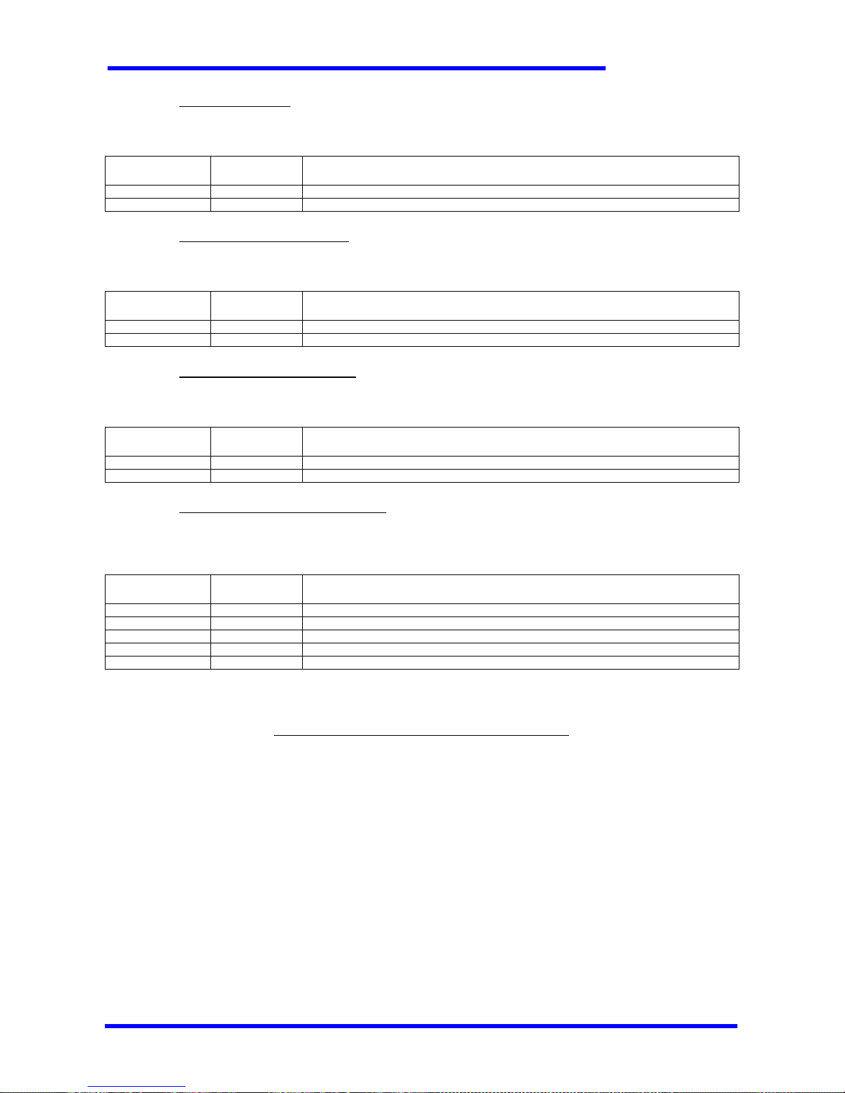
In the calibration menu the display dots give in formation about which parameter is currently being configured in the following way:
Setup of the minimum voltage V
MIN
Example: “V
MIN
= 2.58V”.
In order to provide a better understanding of the display, all the voltage values
related to the “B” semi-functions are reverted with respect to the real value of
the output. The real output voltage is:
5V – (displayed value)
. With this trick
the operator sees a value that increases when he is increasing the m inimum
speed of the function.
E.g. 258 corresponde to a Vmin of 5 – 2.58 = 2.42V
Setup of the maximum voltage V
MAX
Example: “V
MAX
= 4.10V”.
In order to provide a better understanding of the display, all the voltage values
related to the “B” semi-functions are reverted with respect to the real value of
the output. The real output voltage is:
5V – (displayed value)
. With this trick
the operator sees a value that increases when he is increasing the maximum
speed of the function.
E.g. 410 corresponde to a Vmin of 5 – 4.1 = 0.9V
Setup of the acceleration time ramp
(from 1 to 100 steps of 50ms each)
Example: “acceleration time ramp 500ms”.
(10 x 50ms = 500ms)
Setup of the deceleration time ramp
(from 1 to 100 steps of 50ms each)
Example: “deceleration time ramp 500ms”.
(10 x 50ms = 500ms)
In order to change the configured value it is necessary to activate a movement and operate with the Blue and Yellow keys in the
following way:
¾ press the B-KEY to increase the configured value of one step (fine calibration); keeping the B-KEY pressed causes a rapid
increase of the configured value (coarse calibration)
¾ press the Y-KEY to decrease the configured value of one step (fine calibration); keeping the Y-KEY pressed causes a rapid
decrease of the configured value (coarse calibration)
When the movement is deactivated, the new values are stored in the non-volatile memory of the Receiver.
The only way to exit from this menu is a new power-on of the Receiver (i.e. disconnecting the power supply from the receiver).
RC-PCM systems allow to select between two speed sets (normal and reduced working speed), allowing to
independently adjust each parameter of every semi-function in every single speed set. Just select in the Tr ansmitter
the working speed set, activate the function and proceed as described above
.

TECNORD
RC-DBX/PCM/NBM Use and Maintenance Manual Page 21/23
Zero Voltage Adjustment
A special procedure allows to adjust the Zero Voltage, i.e . the vo ltage that is o utput whe n the PRS or JLP joys ticks ar e in their zero
position. This fine adjustment is usually n ot necessary because the dead band of the controlled equipment allows small differences
between the ideal voltage and the real output sig nal in the zero posi tion. Anyw ay it is poss ible to set a d ifferent zer o output voltage for
every function with the following procedure:
1. Keep the Receiver electronics outside its enclosure in order to access the two pushbuttons: Blue K ey (B-KEY) and Yellow Key (YKEY).
2. Press simultaneously the Blue and Yellow keys for about ten seconds, then bypassing the calibration menu, until the dot on the
display’s right digit starts flashing. The current value of the zero voltage for function 1 is displayed.
3. The menu allows to set the zero voltage in sequence for all the imp lemented functions. In order to switch from one func tion
to the next, press simultaneously the Blue and Yellow keys.
In the calibration menu the display dots give in formation about which parameter is currently being configured in the following way:
Example: V
ZERO
(F1) = 2.51V (dot blinking) Example: V
ZERO
(F2) = 2.51V (dot blinking)
Example: V
ZERO
(F3) = 2.51V (dot blinking) Example: V
ZERO
(F4) = 2.51V (dot blinking)
Example: V
ZERO
(F5) = 2.51V (dot blinking) Example: V
ZERO
(F6) = 2.51V (dot blinking)
Example: V
ZERO
(F7) = 2.51V (dot blinking)
8.4 System Menu (for trained staff only)
The System Menu allows basic configurations of the RC-DBX , RC-PCM and RC-NBM systems; depending on the system, the
configuration process involves different steps, which are organized as submenus.
For RC-DBD/DBR systems the sequence of submenus is:
1. Proportional Trigger Acquisition (only useful for DBR, only available with the Service Cab le con nected).
2. Optional Function Setup.
3. System Type Setup
For RC-DBM/PCM/NBM systems the sequence of sub m enus is:
1. EV9 (venting) safety valve mode of operation.
2. EV49 (safety valve) mode of operation.
3. Optional Function Setup.
4. Output Range Setup
Each of the these procedures is outlined in the following paragraphs.

TECNORD
RC-DBX/PCM/NBM Use and Maintenance Manual Page 22/23
Instructions for the system menu setup:
1. Disconnect the power supply from the receiver unit.
2. Keep the Receiver’s electronics outside its enclosure in order to access the two pushbutton s: Blue Key (B-KEY) and Yellow Key (YKEY).
3. Keeping both pushbuttons (B-KEY and Y-KEY) pressed, power the recei ver on. After the ini tializa tion phase, th e unit enters
the System Menu.
4. Release the B_KEY and the Y_KEY.
5. Keep the B_KEY and the Y_KEY pressed for about 5 seconds until the DBX-RX switches to the next submenu, then release both
keys.
6. Repeat step 5 until you reach the submenu where you need to operate.
7. In order to switch from one Setting to the next, press one of the pushb uttons: the B-KEY scrolls forwards, the Y-KEY scrolls
backwards. In order to acquire the proportional trigger, act as described in paragraph 8.4.1.
When the procedure is completed, turn the power supply off in order to end the System Configuration, or press both B-KEY and Y-
KEY simultaneously for about 5 seconds in order to switch to the next submenu.
Troubleshooting
When, after power-on, the display of the DBX-RX shows the indication “_On”, the unit has not entered the System Menu. Power
the Receiver off and repeat the procedure keeping both keys pressed until the unit has entered th e Sys tem M enu.
8.4.1 Proportional Trigger Acquisition
This paragraph is applicable only to systems that i mp lement a prop ortiona l tr igg er. Conne ct the T ran smi tter to t he Re cei ver through
the service cable in order to carry out the proportional tr igger’s acquisition.
The Proportional Trigger acquisition is necessary only when the Transmitter unit has been
replaced. This procedure ensures that the proportional parameters previously stored in the
receiver’s memory are maintained.
When entering the Proportional Trigger Acquisition submenu, a code is displayed, which represents the reading of the proportional
trigger, and the receiver is ready for the self-calibration procedure. follow these steps:
1. Activate a movement: the receiver will not activate any of the outputs, but it will start the self-calibration acquiring the
proportional trigger’s reading.
2. Keeping the movement active, push the proportional trigger to its maximum value and release it several times; during this phase
the displayed code varies together with the trigger’s movements.
3. Release the proportional trigger and deactivate the movement; the receiver stores the trigger’s characteristics in its non-volatile
memory.
Troubleshooting
When, after having completed steps 1 to 4, the dis play shows the indication “Ad.0”, the DBX-RX is not receiv ing any calibration
message from the Transmitter:
¾ Check that the two units are connected properly through the Service Cable.
When, after having completed steps 1 to 4, the dis play shows the indication “000”, the RC-DBX-RU is not receiving any calibration
value for the proportional trigger:
¾ Check that the Emergency Stop Pushbutton is released.
8.4.2 Optional Function Setup
This paragraph is applicable only to systems that i m plement the optional function OPT1/OPT2. This function is configurable in one
of the following operating modes:
Setting Value displayed DESCRIPTION
ON-OFF F_0 OPT1 and OPT2 are standard on-off outputs (EVR and EV9 are not activated)
LATCHING 1 F_1 One latching function: the OPT1 remote switch toggles the OPT1 output on and off
OPT2 is a standard on-off output
LATCHING 2 F_2 Two latching functions: the OPT1 remote switch toggles the OPT1 output on and off, the
OPT2 remote switch toggles the OPT2 output on and off
LATCHING 3 F_3 One latching function: the OPT1 remote switch toggles the OPT1 output on, the OPT2
remote switch toggles the OPT1 output off
PWM (only RC-DBR) F_4 OPT1/OPT2 is a PWM function (EVR and EV9 are activated)
TECNORD
RC-DBX/PCM/NBM Use and Maintenance Manual Page 23/23
8.4.3 System Type Setup
This parameter specifies wether the system has or not a PWM output (i.e. it is an RC-DBD or RC-DBR system). It is configurable
with one of the following values:
Setting Value displayed DESCRIPTION
DBD S_0 On-off system (EVR and EV9 are neither activated nor considered in diagnostics)
DBR S_1 PWM system (EVR and EV9 outputs are activated, diagnostics on EVR is active)
8.4.4 EV9 Mode of Operation Setup
This parameter specifies wether the safety va lve labeled EV9 depends on the Emergency Stop or on the Function ac ti vation. It is
configurable with one of the following values:
Setting Value displayed DESCRIPTION
LEVER 9_L EV9 output is activated when at least one function is active
E-STOP 9_E EV9 output is activated when the E-Stop is released and safe communication takes place
8.4.5 EV49 Mode of Operation Setup
This parameter specifies wether the safety va lve labeled EV49 depends on the Emergency S top or on the Function activation. It is
configurable with one of the following values:
Setting Value displayed DESCRIPTION
LEVER 49L EV49 output is activated when at least one functio n is active
E-STOP 49E EV49 output is activated when the E-Stop is released and safe communication takes place
8.4.6 Analog Voltage Output Range Setup
This parameter specifies which kind of system is driven by the analog voltage outputs of an RC-DBM , RC-PCM or RC-NBM system.
Its value affects the voltage values displayed during parameters adjustments and tells the system if the output voltage must be an
absolute value or ratiometric with respect to the measured battery voltage. It is configurable with on e of the following values:
Setting Value displayed DESCRIPTION
ML4 U_0 MLT FD4 system. Reference values are 0,9V – 2,5V – 4,1V (absolute)
ML2 U_1 MLT L2 system. Reference values are 2V – 4V – 6V (absolute)
DNF12 U_2 12V DNF system. Reference values are 3V – 6V – 9V (ratiometric)
DNF24 U_3 24V DNF system. Reference values are 6V – 12V – 18V (ratiometric)
SMD U_4 SMD system. Reference values are 2V – 4V – 6V (absolute)
WARNINGS (as required by FCC part 15 and IC RSS-210):
This device complies with Part 15 of the FCC Rules. Operation is subject to the following two conditions: (1) this device may not cause
interference,
and (2) This device must accept any interference, including interference that may cause undesired operation.
This equipment has been approved for mobile applications where the equipment should be used at distances greater than 20cm
from the human body (with the exception of hands, wrists, feet and ankles). Operation at distances less than 20cm is stri ctly prohibited.
In any case the message coding and elaboration ensures that no outputs are activated due to radio interferences. Outputs are
activated only when the corresponding messages are received and interpreted as correct.
 Loading...