

Page 1
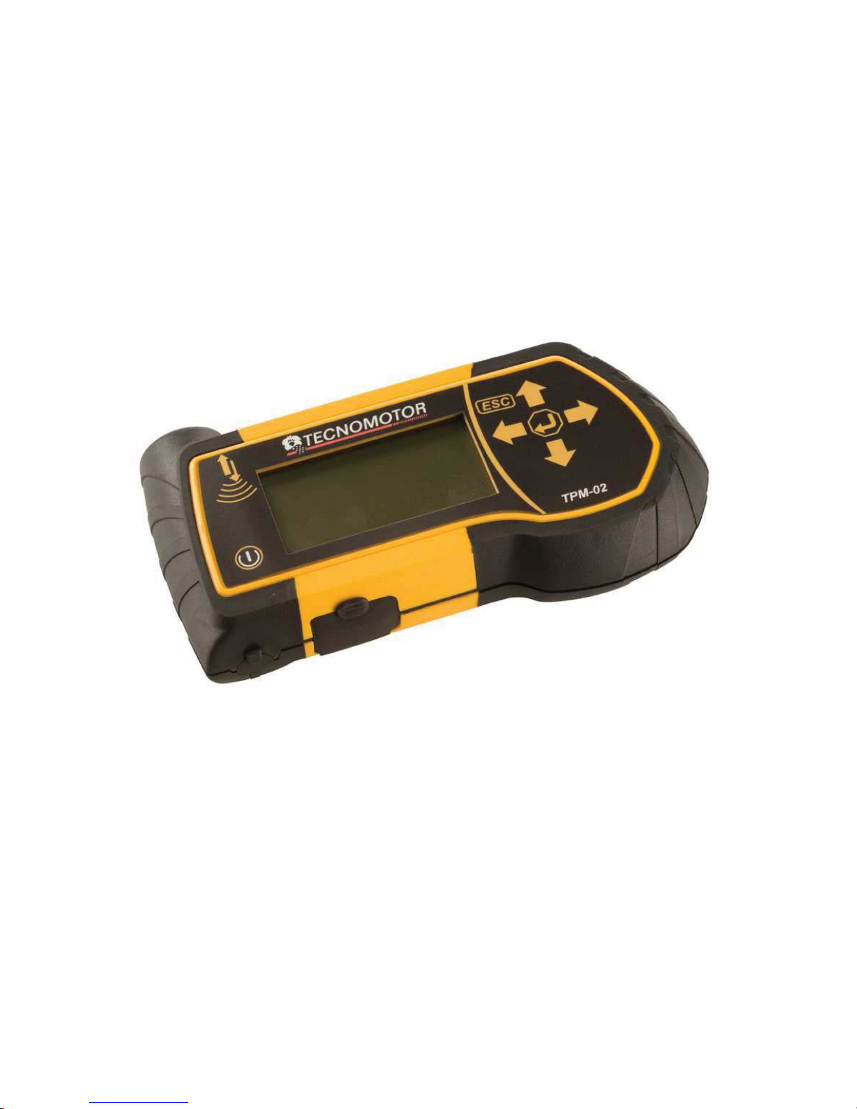
How to use the TPM-02
CONTROL, DIAGNOSIS AND CODING TOOL
FOR TPMS SYSTEMS
Operating Instructions
(ENGLISH)
Page 2

Produced by TECNOMOTOR S.p.A
All rights reserved. This publication may not be reproduced, in full or in part, without
the express written consent of TECNOMOTOR S.p.A. TECNOMOTOR S.p.A
reserves the right to revise or make changes to this publication without prior notice.
Copyright information
All other product and firm names within this manual may be trademarks of other
entities.
Page 3

3
TABLE OF CONTENTS
1. Symbols used in the manual .............................................................................................5
2. Safety rules........................................................................................................................5
3. Upon receipt......................................................................................................................7
4. Package contents...............................................................................................................7
4.1 OBD Option ..................................................................................................................7
5. Maintenance and care .......................................................................................................7
6. How to power on/off the equipment .................................................................................8
7. Recharging the equipment (par.7) ....................................................................................8
8. Settings..............................................................................................................................8
9. What is a TPMS system? ..................................................................................................9
10. TPMS indicator lights ...................................................................................................9
11. Type of sensors............................................................................................................10
12. How to position the equipment ...................................................................................11
13. Functions .....................................................................................................................12
13.1. Keypad .......................................................................................................................12
13.2. Sensor Test................................................................................................................. 12
13.3. Tightening Torques .................................................................................................... 14
13.4. Part Number ...............................................................................................................15
13.5. Tire Rotation and Sensor Replacement...................................................................... 16
13.6. Car Test ......................................................................................................................17
14. Test database ...............................................................................................................18
14.1. Vehicle Data Log: ......................................................................................................19
14.2. Sensors Data Log: ......................................................................................................19
14.3. Upload to PC:............................................................................................................. 19
15. Vehicle remote control test .........................................................................................19
16. Sensor installation/removal procedure ........................................................................20
16.1. Maintenance equipment required for TPMS-equipped tires...................................... 20
16.2. Sensor replacement ....................................................................................................21
16.3. Servicing the sensor with the tire installed. ...............................................................22
17. Tire removal ................................................................................................................23
17.1. Breaking the bead.......................................................................................................23
17.2. Breaking the upper bead ............................................................................................24
17.3. Breaking the lower bead ............................................................................................24
17.4. Tire installation ..........................................................................................................25
17.5. Seating the lower bead ...............................................................................................25
17.6. Seating the external bead ...........................................................................................25
18. Hardware and software requirements for update/data upload PC...............................26
19. UP DATING THE TOOL (PRENDERE PARTE AGGIO TPM1)................................27
Page 4

4
Foreword
Dear Customer,
Thanks for choosing our product. This product has been designed to give you years of
satisfactory service. To ensure this, please read this User Manual thoroughly before
using the product and keep the manual in a safe place for future reference.
Our exhaustive range of products sets a new standard in TPMS (Tire Pressure
Monitoring System) diagnostics while offering an aesthetically pleasing design.
All of our products are designed and manufactured to the highest quality standards.
TPM-02 will prove an indispensable tool for:
• Checking sensor operation before servicing the tires (when vehicle is brought
in for service or repair).
• Establishing proper operation of the TPMS system when the customer picks up
the vehicle.
• Determining why the “Tire Pressure” (TPMS) light turns on.
• Ensuring that sensor provides accurate pressure and temperature readings.
• Measuring the pressure of wireless tires (with no need to unscrew valve cap
and connect a compressed air line with pressure gauge).
• Enabling time-saving, safe repair procedures with reference information (such
as torque figures or part numbers) always handy to avoid damage due to
improper procedures.
• Ensuring that sensors are refitted in their original positions after service
(positioning tool)
• Perform a TPMS coding operation after a sensor replacement.
Page 5
5
1. Symbols used in the manual
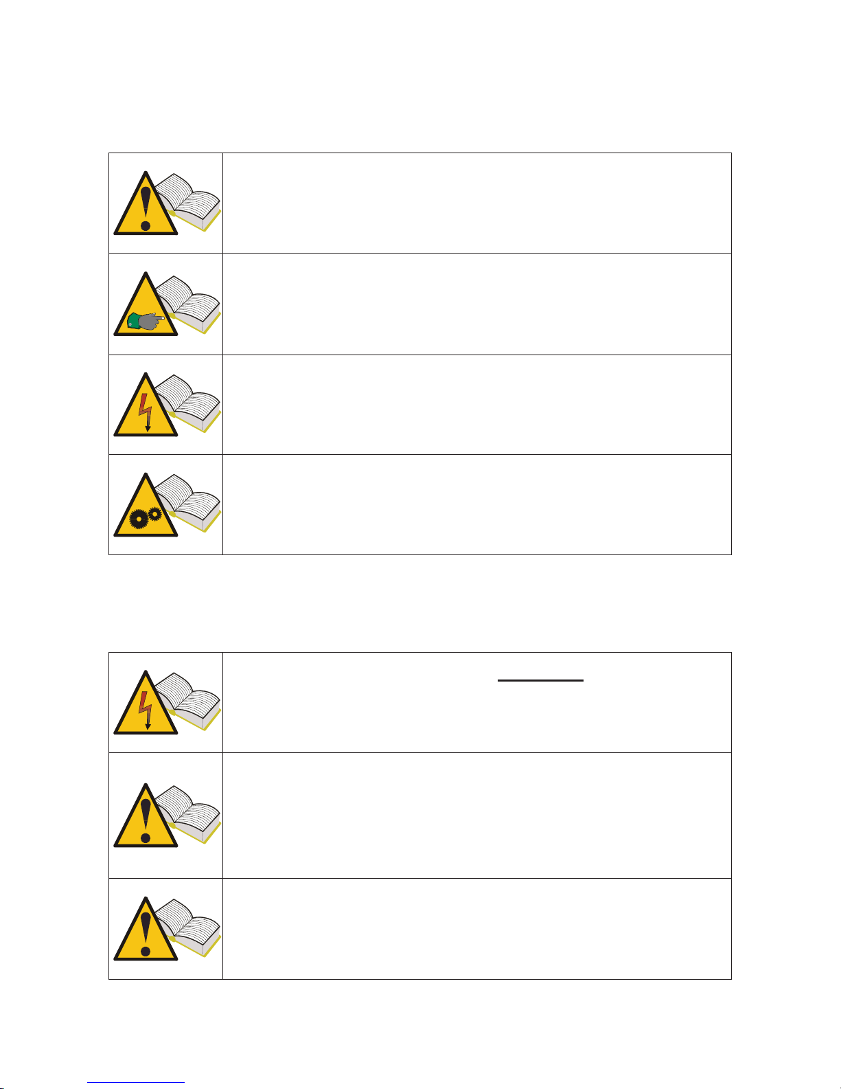
This symbol calls attention to important information concerning
operation and safety.
This symbol calls attention to important information and tips aimed
at ensuring proper operation of the equipment.
This symbol calls attention to important instructions concerning
maintenance of electrical parts.
This symbol calls attention to important service instructions.
2. Safety rules
To recharge the equipment, it is mandatory to use the power
supply unit supplied by Tecnomotor S.p.A. Item No. 1800155.
Tecnomotor shall not be liable for damage to equipment in the
event other power supply units are used.
This appliance has been designed and tested to ensure safe
operation.
The user is required to observe the information and warnings
p
rovided in this manual to ensure safe operation and preserve the
safety features of the appliance.
WARNING : For equipment package maintenance and handling
after equipment installation, the provisions of Legislative Decrees
DDLL 626 of 19/9/94 and 242 of 19/3/96 apply. Use appropriate
tools to open package.
Page 6
CAUTION : USE UTMOST CARE !!!
Do not allow operation of this equipment by unqualified
persons. It is the owner's responsibility to keep warning labels
and rating plates clean and legible.
This manual is subject to changes and updates.
Be sure to read the update and customization instructions included
in this manual.
The manual is divided into sections for ease of reference. Manual
instructions - especially those concerning maintenance - are
intended for use by specialized technical personnel with good
knowledge of mechanics, electromechanics or of the operation of
computerized unit-based systems. The system has been designed
to facilitate operation and troubleshooting, with a wide
range of display messages providing detailed indications to help
locate problems.
Please read these instructions carefully before operating the
equipment.
Collect this manual and all literature supplied with the equipment
in a file folder and keep it with the machine where operators can
easily access it.
Make sure installation has been performed in compliance with all
applicable regulations and standards.
Read this manual carefully and learn how to use the equipment
properly and safely.
Be sure to observe applicable accident prevention rules when
operating and servicing the equipment.
In the event of unauthorized changes to the equipment, the
manufacturer shall not be liable for any resulting damage
or incident. Please note that bypassing or removing safety devices
is in violation of workplace safety rules in force in the user's
country.
CAUTION
Changes or modifications not expressly approved by the party
responsible for compliance with the FCC Rules could avoid the
users’ authority to operate this equipment.
6
Page 7

7
3. Upon receipt
Upon receipt, check packing and product components for damage in the presence of
the carrier. Liability for transport damage attaches to the forwarding agent or carrier.
Report any damage, giving details of the nature and severity of the damage, in the
shipping document and file a claim against forwarding agent or carrier.
4. Package contents
Package contains:
• 1 TPM-02 sensor tester
• 1 USB connection cable for PC connection
• 1 CD-ROM with product update utility
• 1 externatl Power Supply.
4.1 OBD Option
Through this optional it is possible to connect the tool to the ECU of the vehicle in
order to carry out the following procedures:
Flashing the ECU when the sensor is replaced
Flashing the ECU when rotating the tires
Adjust when possible the alarm threshold, set the winter tires etc.
Read and delete the malfunctions
The optional kit includes a SD card and intelligent OBD cable
5. Maintenance and care
Please follow these instructions to avoid malfunction or unexpected failures:
- Do not drop or knock the equipment.
- Avoid spilling fluids on the equipment.
- Do not use batteries other than those specified in this manual.
- Do not service the equipment when it is in operation.
- Do not clean the equipment when it is in operation.
- Keep the package for safe handling
Page 8
8
6. How to power on/off the equipment
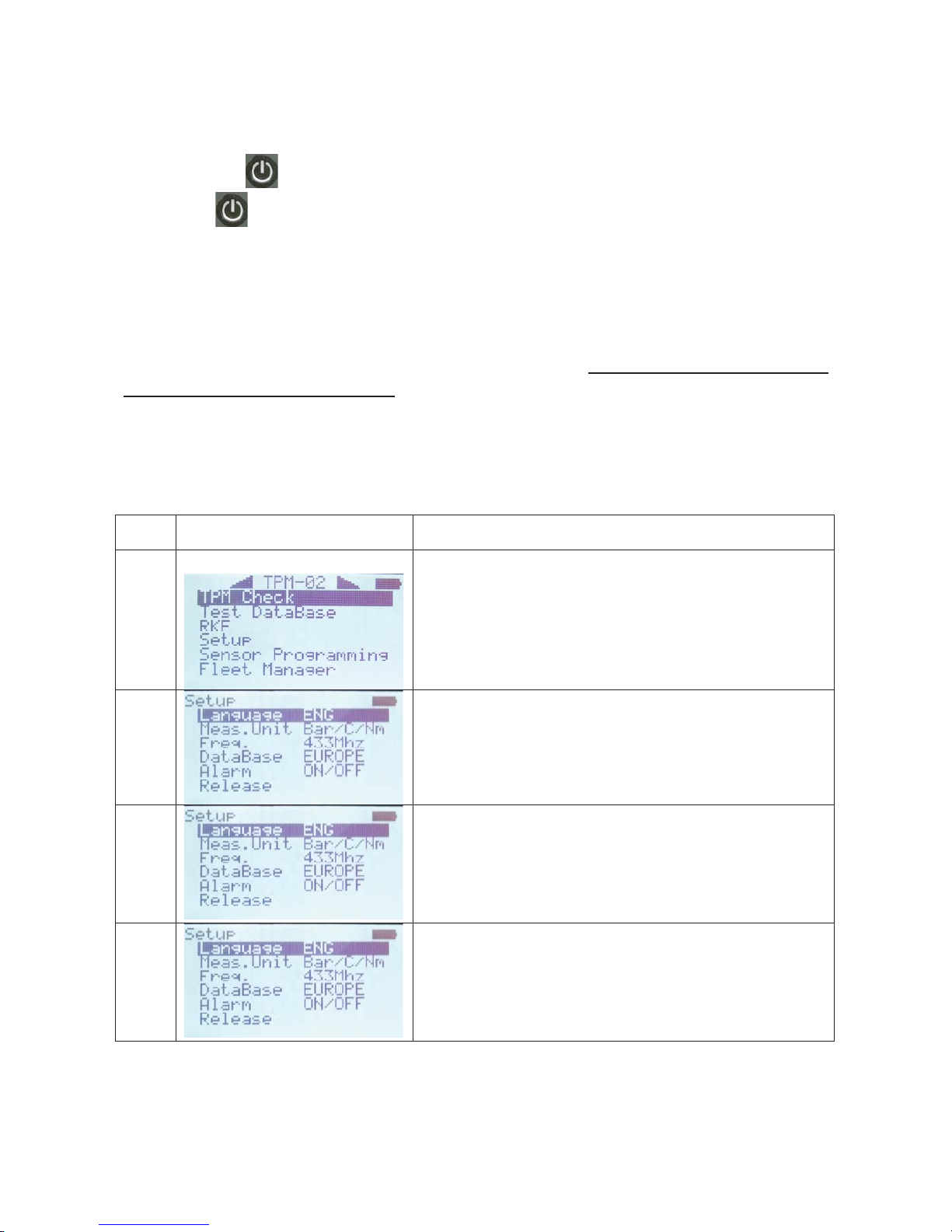
Touch the key to power on the equipment.
Touch key
to power off the equipment. The equipment will power off
automatically when no buttons have been pressed for 10 minutes to save battery life.
7. Recharging the equipment (par.7)
The batteries placed inside the equipment are charged. The equipment may only be
recharged using power supply . In the event the equipment should run fully flat, it
will take about 3 hours to fully recharge it.
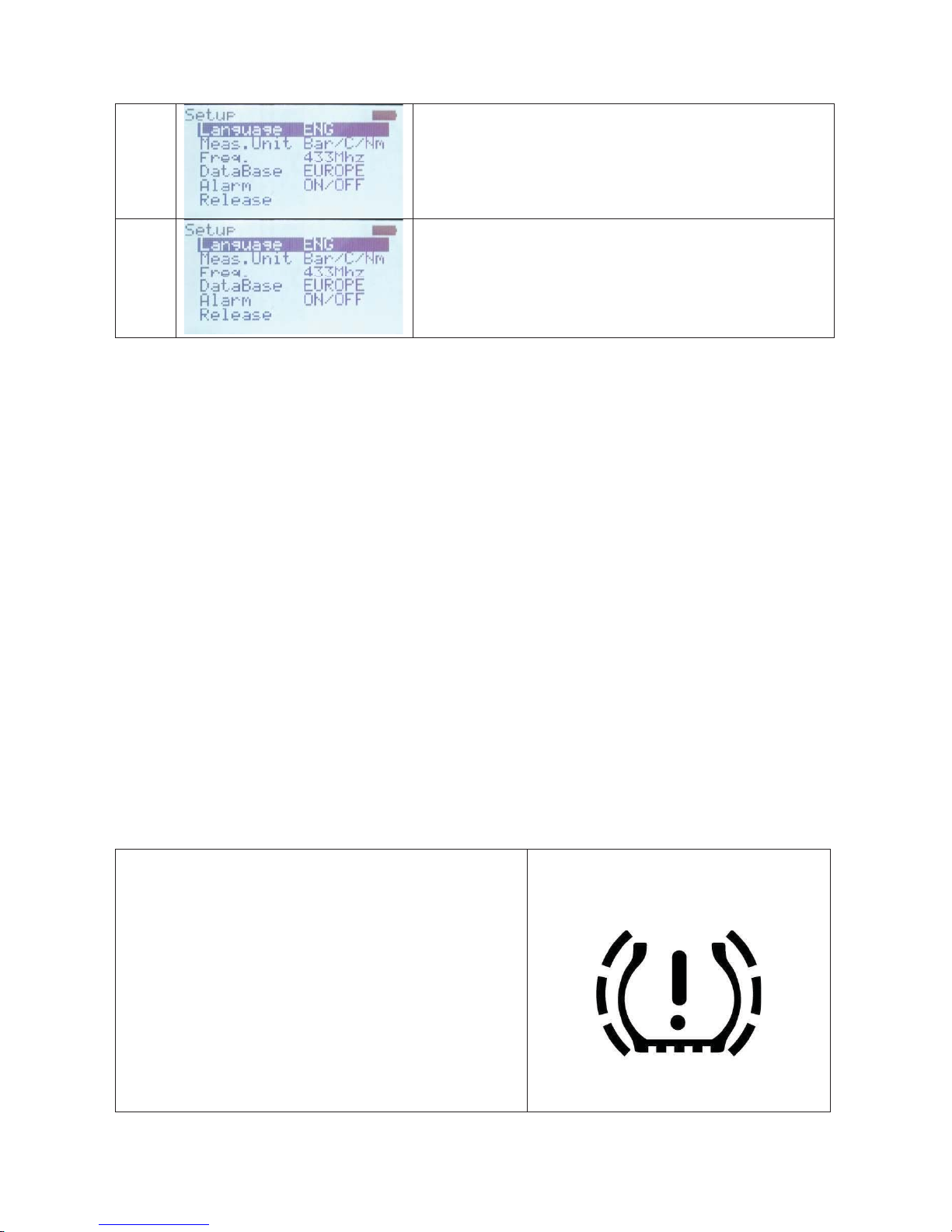
8. Settings
Step Screen page Description
1 Select option SETUP from the main menu page
2 Selecting LANGUAGE user can choose from:
French, Italian, English, Portuguese, Spanish and
German
3 Selecting MEASURMENT UNIT user can select
it for different parameters.
Pressure (bar / psi / KPa)
Temperature (C/F)
Torque (Nm / FtLbs)
4 Selecting COUNTRY it’s possible to setup the
Operating Frequency of the tool.
USA (315Mhz)
EUROPE (433Mhz)
Page 9
9
5 Selecting ALARM it’s possible to enable or
disable SOUND and VIBRATION
6 Selecting RELEASE the tool will show software
infos:
FW VERSION
DB VERSION
SERIAL: XXXXXX
9. What is a TPMS system?
The TPMS or Tire Pressure Monitoring System continually monitors tire pressures
and temperatures and sends the information to the body computer to have it displayed
on the instrument panel. The system is made up of an ECU placed inside the cab that
receives radio frequency pressure and temperature signals from four sensors installed
inside the tires.
When the vehicle is running, the sensors transmit their signals every 20-30 seconds
approximately. In the event of a significant pressure variation, transmission interval is
shortened to 8-10 seconds.
When the vehicle is at standstill, transmission interval may vary between 10 and 40
minutes, depending on the type of sensor installed.
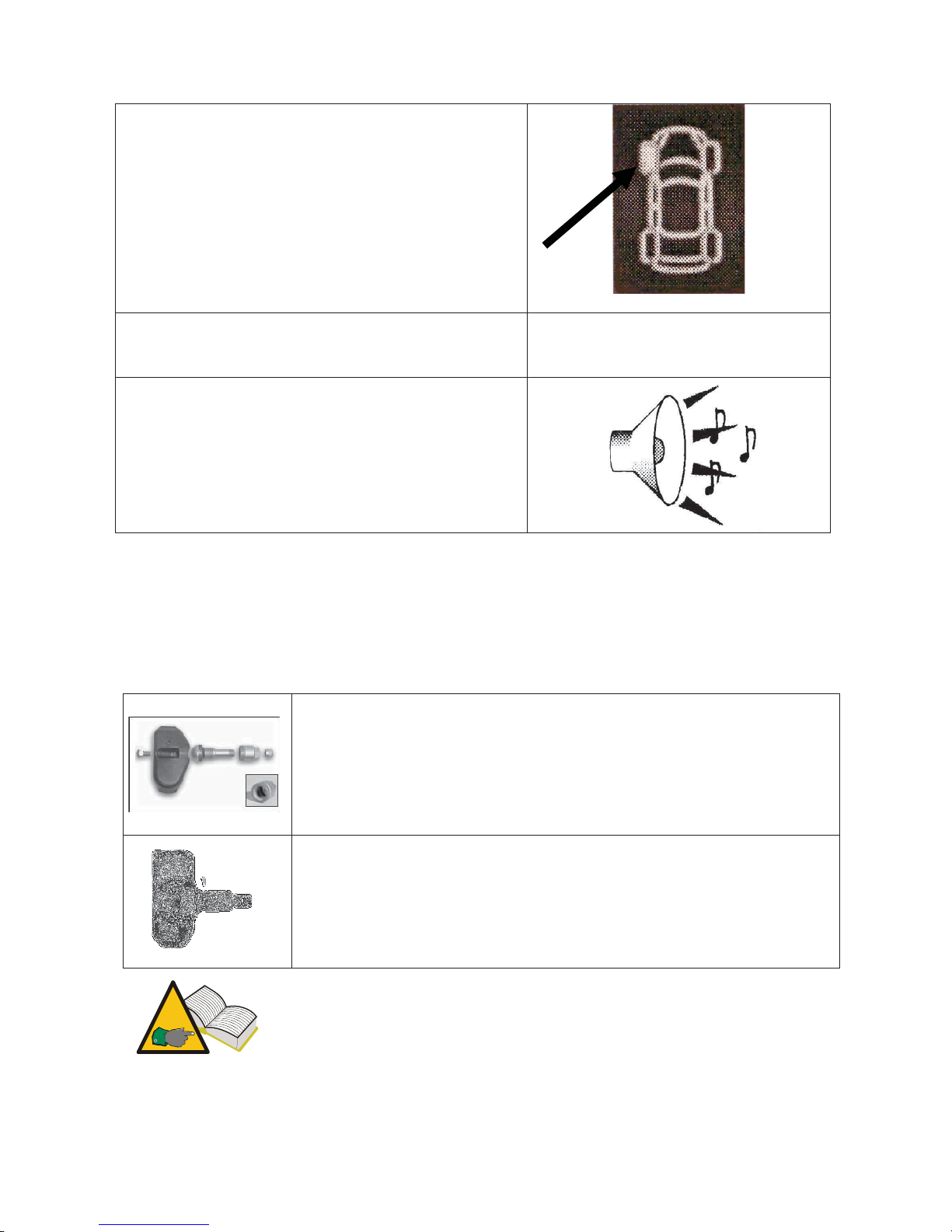
10. TPMS indicator lights
Outlined below are the most significant TPMS indicator lights.
Depending on the type of vehicle, this light may
indicate one of the following conditions:
• Turns on to indicate that the pressure of
one or more tires is above or below the
specified rated pressure.
• Turns on to indicate a TPMS malfunction
(for instance, when one of the sensors is
malfunctioning).
•
Light operation may vary to differentiate
indications when tire pressure has
crossed the warning or alert thresholds.
Page 10
10
Tire location indicator
This light indicates the location of the under- or
overinflated tire.
The light may be associated with a display
message.
Display messages “Check tire pressure
”
Audio Alarms
Audio alarm for wrong tire pressure or TPMS
malfunction
11. Type of sensors
Sensors may be grouped into two broad categories, depending on whether they are
incorporated into valve body or not as shown in the table below.
Design 1
The valve shown in the figure is made up two elements:
- pressure sensor
- valve body
Valve body is made up of four elements: retaining screw, valve,
nut and valve cap.
Design 2
The valve shown in the figure is a single component that
incorporates both pressure sensor and tire valve. This valve
design also features a grommet/O-ring (to keep air from escaping
past the hole in the rim), a nut and the valve cap.
In design 1, valve and sensor may be replaced separately when
needed; in design 2, valve and sensor are replaced as a set.
Page 11
11
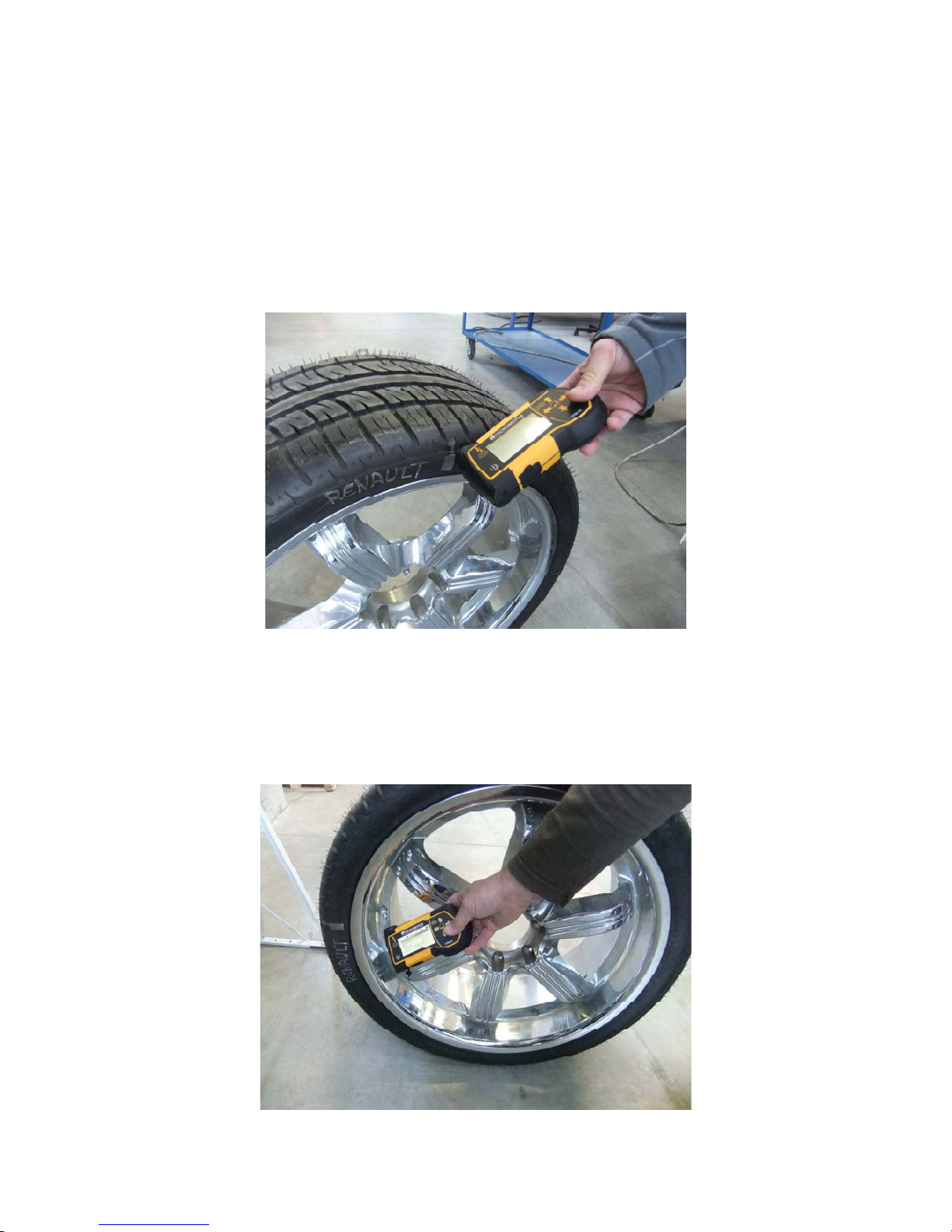
12. How to position the equipment
The equipment incorporates a low-frequency antenna to transmit sensor data. An
arrow
;
;;
;
on the top panel of the equipment shows where the tip of the antenna is
located. In order to properly energize the valve, the equipment must be aligned with
valve body as shown in the figure below. Anyway, the equipment must be placed
over the tire and tilted towards valve body.
Correct position
This set-up ensures the ideal condition for low-frequency data transmission to the
sensor installed inside the tire. Other set-ups, like that shown in the next figure, could
lead to noise between equipment and valve. This prevents communication between
the two and makes accurate sensor diagnosis impossible.
WRONG position
Page 12
12
13. Functions
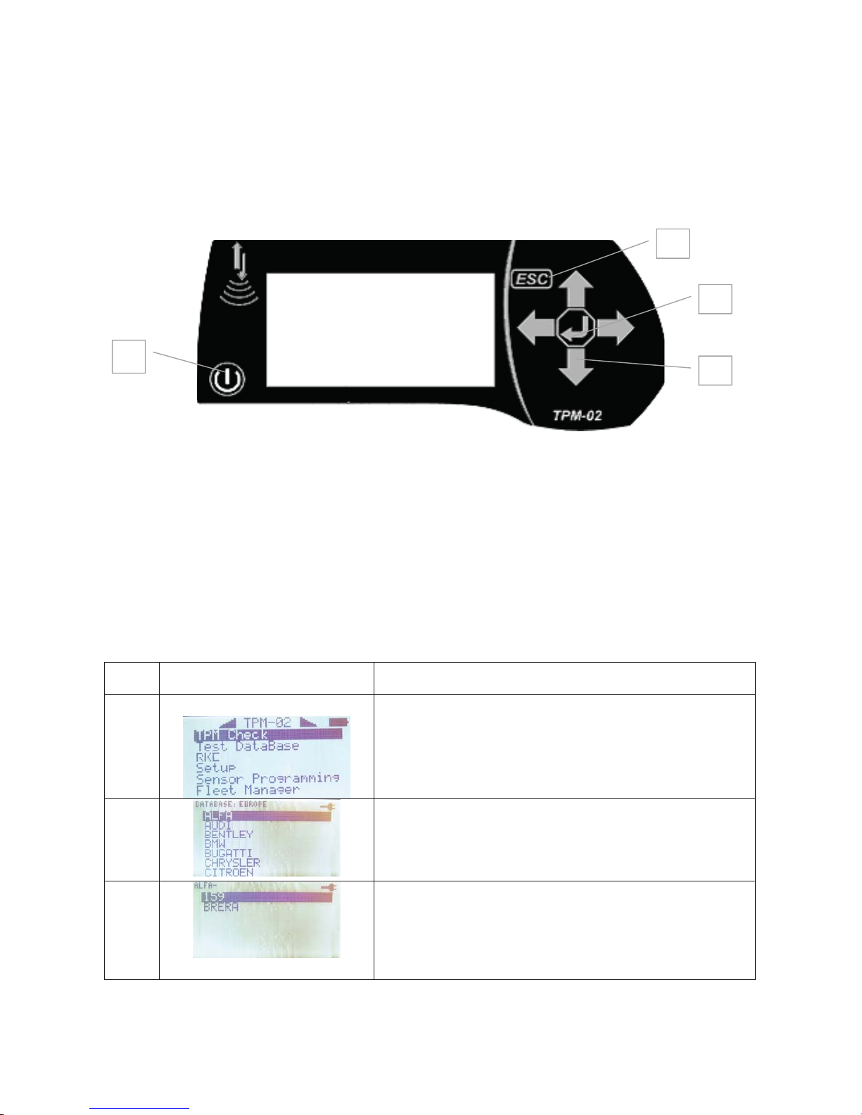
13.1. Keypad
The equipment is equipped with a 7-button keypad featuring:
1) On/Off button to power on and off the equipment
2) Up, Down, Left e Right arrow buttons for browsing
3) Enter button to confirm selection or acknowledge display messages
4) Esc button to go back to previous menu or cancel an operation in progress.
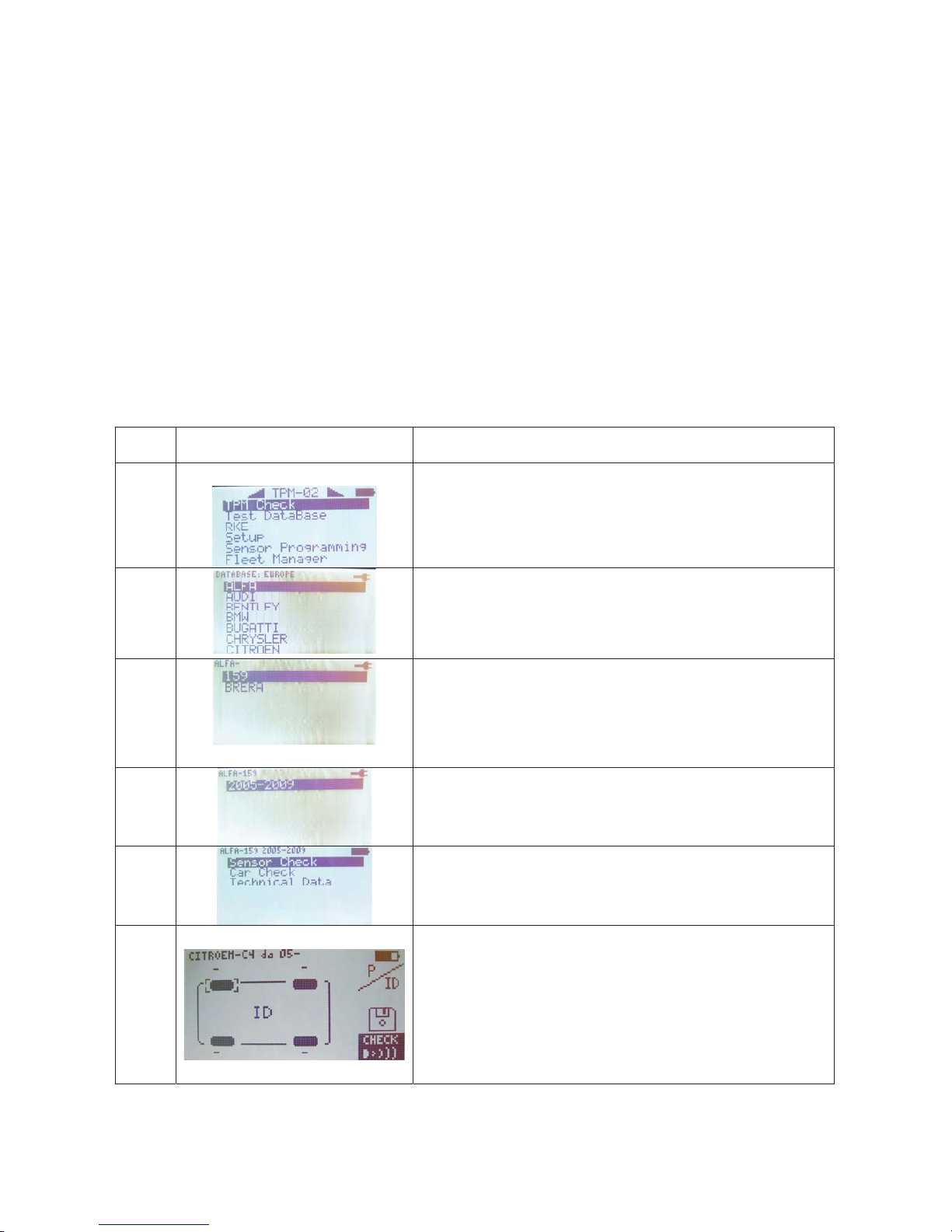
13.2. Sensor Test
When you select this function, the tester will attempt to actuate the sensor and
configure the receivers to verify correct valve data transmission.
Step Screen page Description
1 Select option TPM CHECK from the main
menu page
2 Select vehicle make
3 Select vehicle model
1
2
3
4
Page 13
13
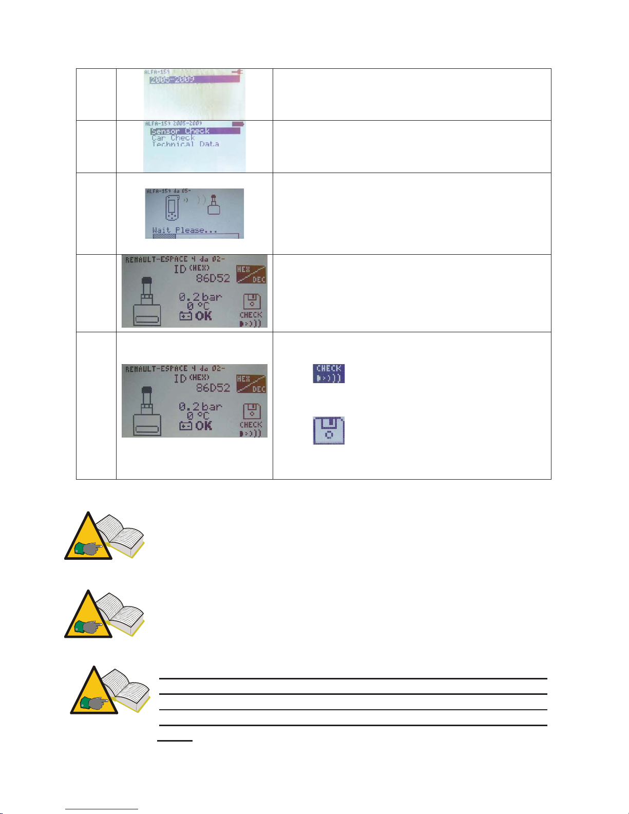
4 Select vehicle's year of manufacture
5 Select Sensor Check
6 The tester will attempt to actuate the sensor by
sending it a low-frequency signal.
7 If the tester receives the correct data from the
valve, it will beep and display pressure,
temperature, battery state and ID (identification
code). Press Enter to go to the next menu.
8 This menu offers the following options:
• ESC to go back to tester main menu.
•
to repeat the test without going back
to main menu in the event the tester was
unable to communicate with the sensor.
•
lets you save the test to tester
memory.
Step 7: In some cases, the sensor will transmit data if it senses a
pressure variation of a least 0.2 bar in the tire. When the tester shows a
message reading Deflate tire, it means that you need to induce a
pressure variation in order to enable valve data transmission.
Step 7 : If the tester receives data in the wrong format but signal is the
correct frequency, message “f=433MHz Sensor not recognized” is
displayed. If the tester did not receive the frequency signal either,
message “No signal received”.
Step 8: When ID and pressure data is not displayed, the sensor is
likely to be malfunctioning. To determine whether the sensor is
actually faulty, test the other vehicle sensors; if ID and pressure
values from the other sensors are displayed correctly, the sensor is
faulty.
Page 14
14
Step 8: battery state “ko” means that sensor battery is flat and sensor
must be replaced. Battery state “vv” means that the battery is not fully
charged; when this is the case, you might want to replace the sensor
to be on the safe side; definitely replace the sensor if the customer
claimed intermittent TPMS light operation. Battery state “ok” means
that sensor battery is in good working order.
13.3. Tightening Torques
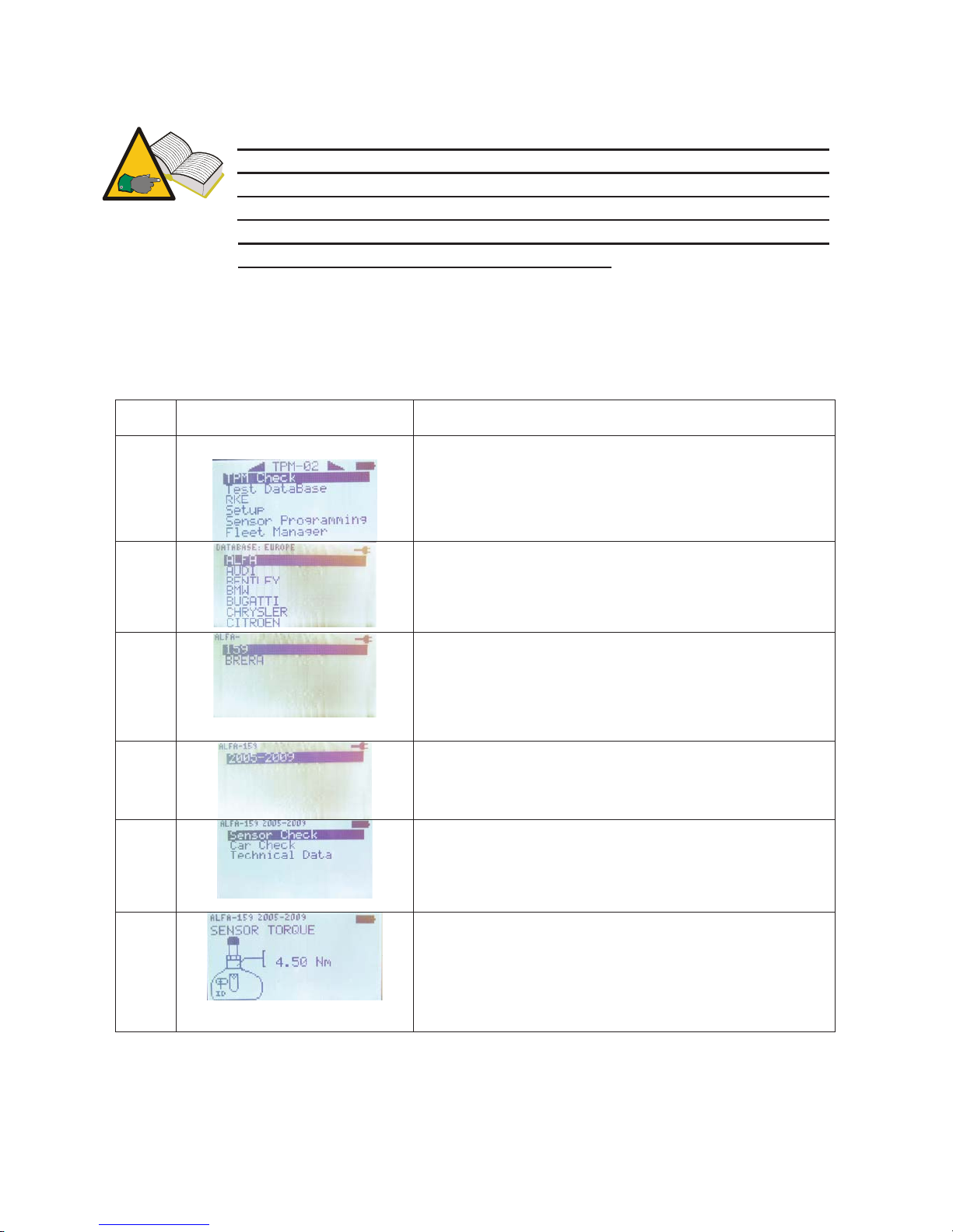
This function provides an overview of sensor and wheel tightening torques;
overtightening may cause irreparable damage sensor and wheel rim.
Step Screen page Description
1 Select option Select vehicle from the main menu
page
2 Select vehicle make
3 Select vehicle model
4 Select vehicle's year of manufacture
5 Select Technical Data
6 The tester displays:
• Sensor TRQ Tightening torque for
pressure sensor
Sensor SCR
1
Tightening torque for retaining
screw of pressure sensor valve body.
Page 15
15
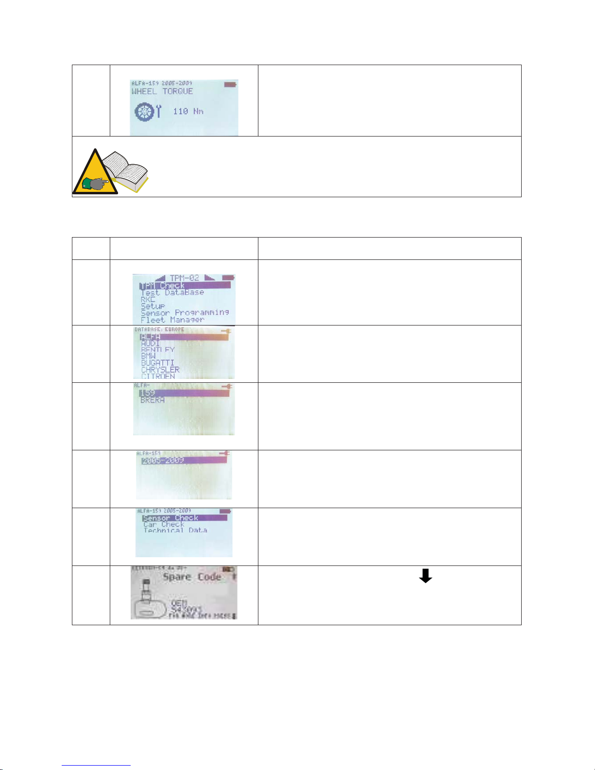
7 Clicking 3 time on the down arrow will show
also the Wheel TRQ
1
Sensor screw tightening torque is only provided for design 1, see
paragraph 10 in this manual.
13.4. Part Number
Step Screen page Description
1 Select option Select vehicle from the main menu
page
2 Select vehicle make
3 Select vehicle model
4 Select vehicle's year of manufacture
5 Select Technical Data
6 Select 4 times More info press
The tester displays the part number of the
appropriate valve for the selected vehicle. OEM
part numbers are displayed.
Page 16
16
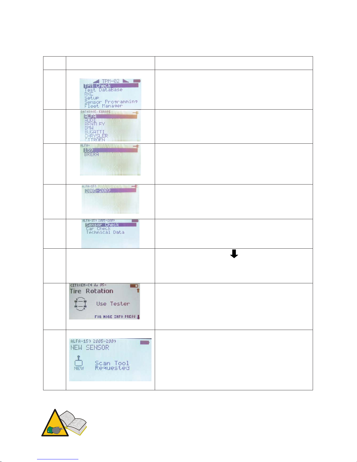
13.5. Tire Rotation and Sensor Replacement
Step Screen page Description
1 Select option TPM CHECK from the main
menu page
2 Select vehicle make
3 Select vehicle model
4 Select vehicle's year of manufacture
5 Select Technical Data
6 Select More info press
7 This calls up a menu with the following options:
• “TYRE ROTATION” provides
information on what tool or technique
should be used when rotating sensors.
8
• “SENSOR REPLACEMENT” provides
information on what tool or technique
should be used when rotating sensors.
Step 6 and 7 - Possible indications are:
Page 17
17
- “Tester”: it indicate that it is necessary to flash the ECU of the vehicle through
OBD (p.n. 8-64500013)
- “Manual”: it indicates the a manual procedure exists and then it is necessary to
check the vehicle book
- “Drive”: This means you need to drive the vehicle at steady speed for a few
minutes (refer to vehicle manual)
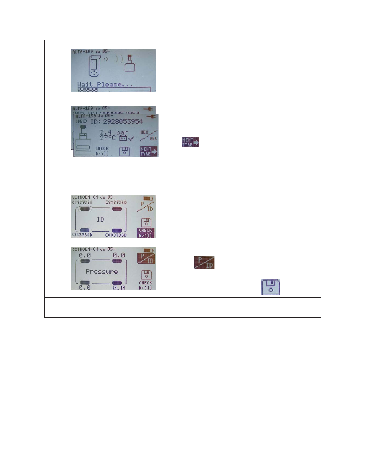
13.6. Car Test
To promote transparent customer relationships, this function may be used to establish
correct operation of tire sensors when your customer brings in the vehicle for service
or picks it up.
Step Screen page Description
1 Select option TPM CHECK from the main
menu page
2 Select vehicle make
3 Select vehicle model
4 Select vehicle's year of manufacture
5 Select Car Check
6 Through the arrow keys select the tire to be
tested. Press Enter to confirm when You are
ready.
Page 18
18
7 The tester will attempt to actuate the sensor by
sending it a low-frequency signal.
8 If the tester receives the correct data from the
valve, it will beep and display pressure,
temperature, battery state and ID (identification
code).
Press
to test the next wheel; press Esc to
return to step 6.
…. Steps 6 through 8 are repeated to test the other
vehicle wheels.
18 The tester displays a screen page with ID.
19 Is possible to see also the pressures collected
,selecting
Once the tester is finish, is possible to save it
into the test database selecting
The latter case is likely due to an oversight during the test procedure. Two valves with the same ID
installed on the same vehicle are a rare occurrence.
14. Test database
This function lets you manage, view and repeat any tests performed during past
sessions.
Page 19
19
14.1. Vehicle Data Log:
This function lets you view Vehicle Test results saved during past sessions. You may
also use the “Location Test” function to determine whether the sensors installed on
the vehicle are still in the same positions as when the test was saved.
Specifically, you may perform the “vehicle test” when the vehicle
is brought in (as outlined in paragraph 12.6) and save the test;
upon vehicle delivery, you may call up the vehicle log and check -
together with the owner - that sensors are operating properly and
are still in the same positions as when the vehicle was brought in. This way, you
can establish that any TPMS malfunction has nothing to do with tire repair.
14.2. Sensors Data Log:
This function lets you view Sensor Test results.
14.3. Upload to PC:
This function lets you upload all data stored in the tester to your PC via the USB port.
15. Vehicle remote control test
The purpose of this function is to check radio frequency data transmission from
vehicle remote control devices and battery charge. To ensure accurate test results,
perform this test well away from any radio frequency signal sources.
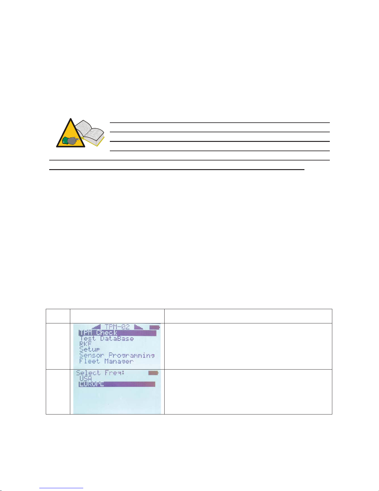
Step Screen page Description
1 Select option Remote Test from the main menu
page RKE
2 Select frequency
Page 20
20
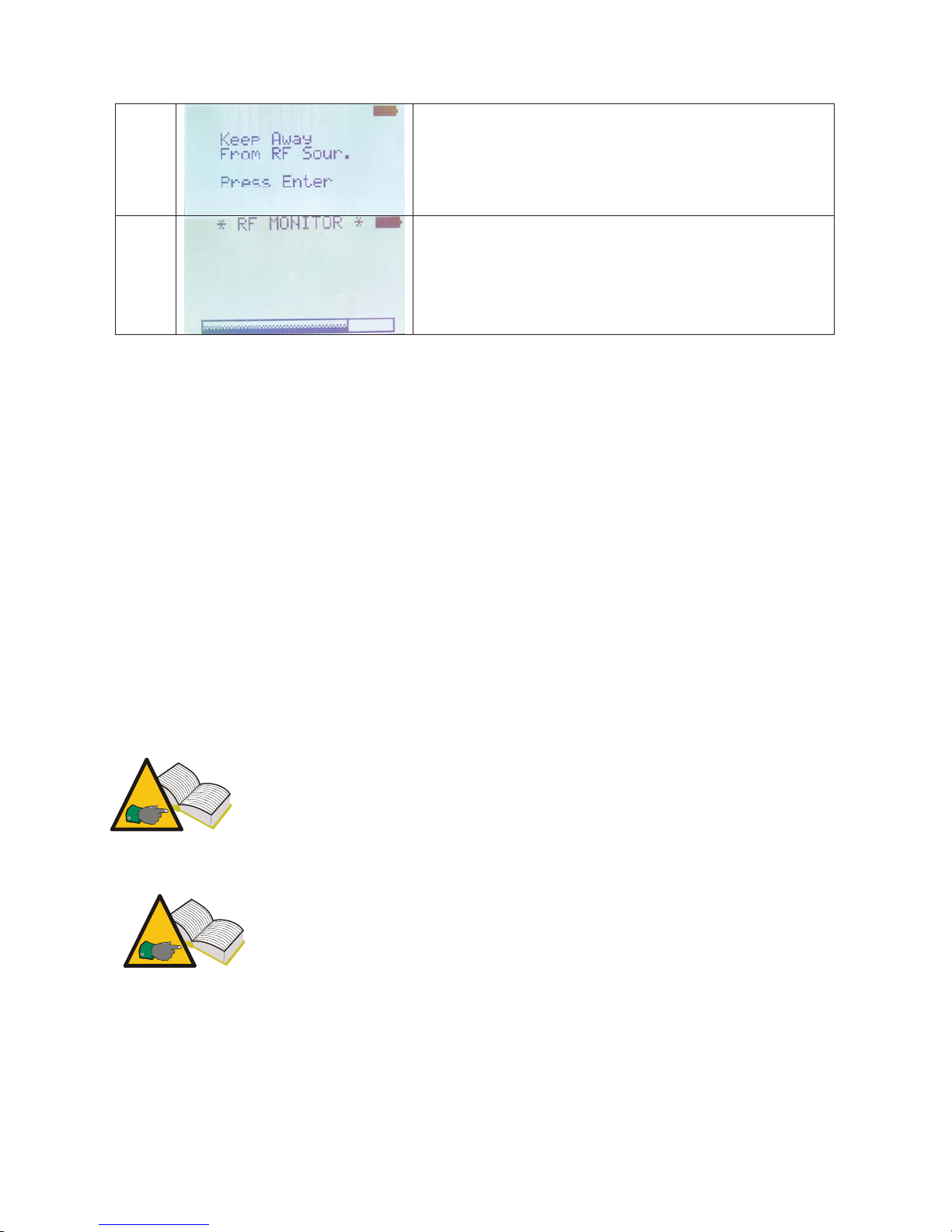
3 A message to move away from other radio-
frequency source, such as automatic gates,
wireless devices, is displayed.
Then press ENTER
4 The diagnostic tester will display RF monitor as
well as the number of data received on frequency
in use.
Press ESC to exit
16. Sensor installation/removal procedure
16.1. Maintenance equipment required for TPMS-equipped tires
TPMS-equipped wheels normally use low-section tires with high speed rating or run
flat tires, either self-supporting or auxiliary-supported (PAX System or SR Support
Ring tires with insert). Tire installation/removal procedures are similar to those for
conventional tires, except for auxiliary-supported run flat tires.
To install and remove TPMS-equipped wheel tires, we recommend using the latest
tire changers which are especially suited to install low-section tires or large-size tires
on alloy wheels. It is essential that the tire changer be equipped with plastic pressure
rollers so as to ensure correct pressure during installation without damage to wheel
rim, sensor and tire bead. Shown in the picture is a tire changer suitable for TPMSequipped wheels.
For auxiliary-supported run flat tires (PAX System or Support Ring)
equipped with TPM sensors, you will have to use tire
removal/installation equipment approved by the tire manufacturer.
These tires require special accessories and the installation/removal
procedures are different from those used for standard tires.
Follow the installation and removal instructions and procedures
provided by the manufacturers of tire, sensor, vehicle and tire
removal/installation equipment. The information provided herein is
general information applicable to most sensors found in the market.
In addition to the appropriate tire changer, when you change sensors you will also
need suitable sensor replacement kits that include one or more wrenches, O-rings,
valve caps in different colours, valve body and valve insert. Kit contents may vary
depending on sensor type (see paragraph 10.0) and brand.
Page 21

21
16.2. Sensor replacement
Installation and removal procedures vary slightly depending on sensor model.
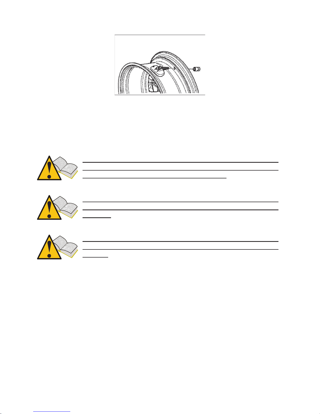
A standard procedure for the valve-and-sensor assembly configuration (design 1,
paragraph 10) may be as follows:
1. loosen the retaining screw so the sensor can move freely.
2. unscrew the nut completely
3. remove valve body from its seat; the sensor must be free to move otherwise the
valve will not come off.
4. unscrew the retaining screw and remove valve body.
For incorporated sensors (design 2, paragraph 10), simply perform steps 2 and 3 of
the above procedure.
A standard procedure for the valve-and-sensor assembly configuration may be as
follows:
1. Obtain a complete replacement kit including TPM sensor and all other parts
(valve body, retaining screw, nut, valve cap).
2. Insert valve and O-ring into valve seat. Install the nut to retain valve to wheel
rim, but do not tighten yet. The nuts have a small plastic grommet inside that
must be sheared upon final tightening. When the nut becomes hard to turn,
stop.
3. Install sensor onto valve body and secure it with the retaining screw. These
sensors can be installed at varying angles to accommodate different rim
configurations. Before final tightening, look up the sensor manufacturer's
instructions to make sure that torque is correct, that sensor is in the correct
position (i.e. touching the wheel rim or not) and that the external portion of the
sensor is below bead seat. If these requirements are not met, the sensor might
damage during tire installation.
4. Tighten the valve nut firmly (the grommet inside the nut must break) to the
torque specified by the sensor manufacturer.
5. Install the tire.
Standard procedure for incorporated sensor (design 2)
1. Make sure the O-ring is in place on the valve body and insert it into the rim
hole.
2. Fit the nut to secure the sensor into place so that is parallel with the rim and
tighten to the torque specified by the TPMS manufacturer.
3. Install the tire.
Page 22
22
Fig 01
For valve-and-sensor assemblies, replace valve body, screw and nut, O-ring, valve
insert and valve cap each time tire is replaced or serviced. For incorporated sensors,
replace valve insert, nut, O-ring and valve cap. Appropriate replacement kits are
available from TPM sensor manufacturers.
You may retrieve the correct tightening torques for sensor
installation and view them on tester display using the function
described in paragraph 12.3 “Tightening torques”.
Manufacturer (OEM) part numbers for sensors may be viewed on
tester display using the function described in paragraph 12. “ Part
Number”.
Check sensor for proper operation before refitting the wheel to avoid
removing the wheel again in the event the sensor needs to be
replaced.
16.3. Servicing the sensor with the tire installed.
The instructions outlined above require tire removal. Some tire changers equipped
with double rollers enable sensor inspection and replacement with no need to remove
the tire. If you have this type of equipment, please refer to the manufacturer's
instructions.
Page 23
23
17. Tire removal
TPMS-equipped wheels with internal sensors must be handled with great care during
tire removal and installation procedures. A suitable tire changer and proper bead
lubrication will greatly facilitate these operations.
Test sensor for proper operation before proceeding.
17.1. Breaking the bead
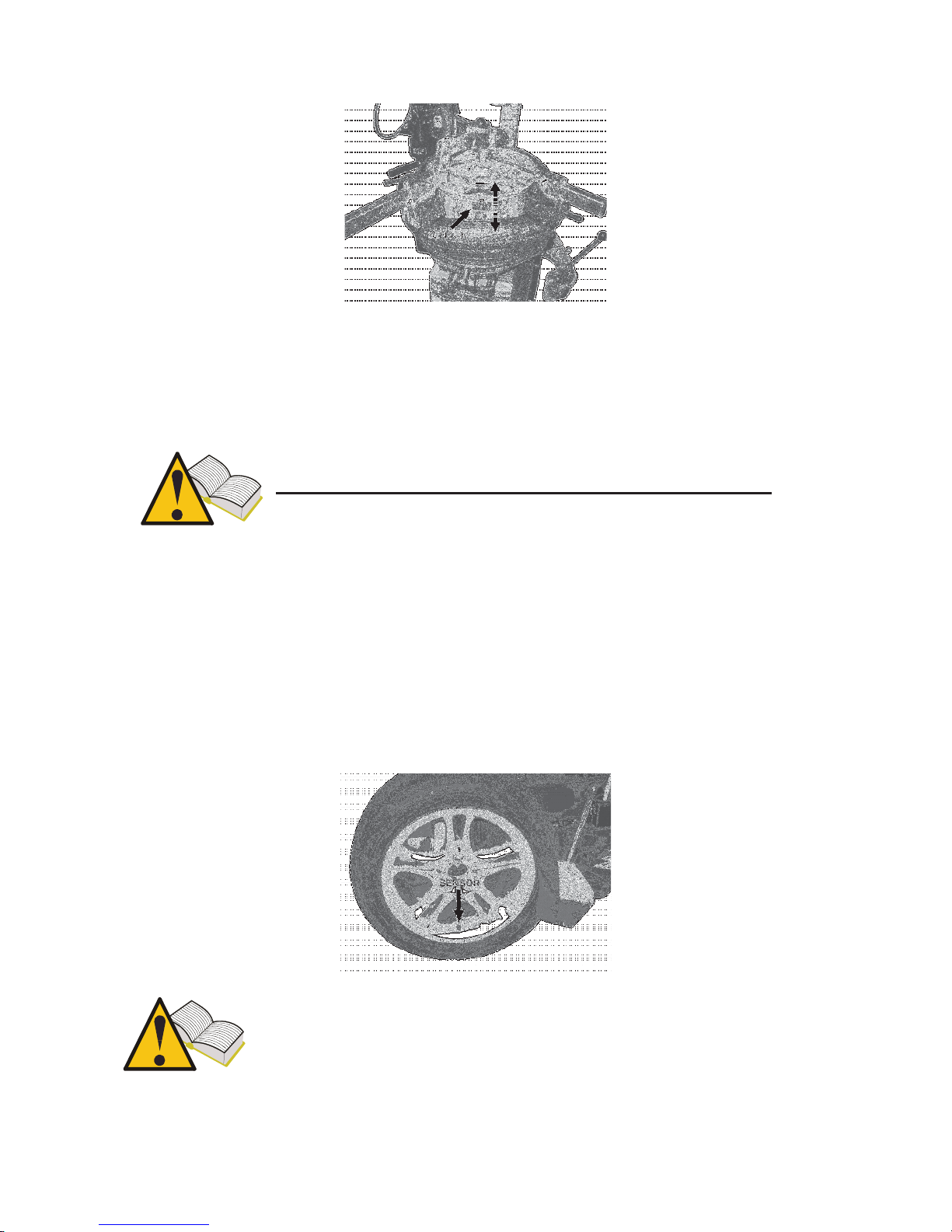
Remove valve cap and insert and wait until tire deflates before breaking the bead.
Many bead breakers use a blade to break the bead loose from the wheel; with this
kind of equipment, position the wheel so the sensor is at 6 o'clock before beginning.
If the bead does not break loose at the first attempt, remember to insert the bead
breaker blade away from sensor body throughout the procedure. If you are using a
bead breaker with rollers, make sure the roller will not push the bead into the wheel
well or the bead might hit the sensor during rotation.
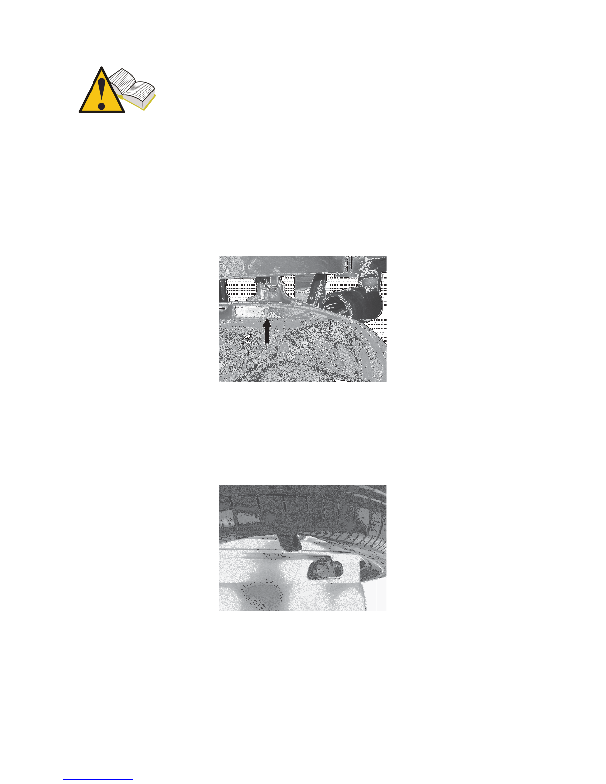
If you are using a blade-type bead breaker, make sure the blade is
well away from the sensor. Otherwise, the blade might push the tire
bead into the wheel and it might contact and damage the sensor.
Page 24
24
If you are using a bead breaker with rollers, make sure the tire bead
is not pushed too deep into the wheel well as it is stretched around
the wheel rim, or it might damage the sensor
.
17.2. Breaking the upper bead
Lock the wheel onto the tire changing equipment - fitted with plastic shoes if
servicing a light alloy wheel - lubricate the bead and position the head so that the
sensor is just behind or under the head. Break the bead using the plastic-guarded lever
and place bead over head chisel. Slowly turn the wheel clockwise keeping distance
between bead and sensor steady.
17.3. Breaking the lower bead
To break the lower bead, place the head just before the sensor. Pry the tire bead up
and over the head chisel, be careful not to hit the sensor. Slowly turn the wheel
clockwise until prying out the tire. Check sensor for damage.
Page 25
25
17.4. Tire installation
Before installing the tires, check for the following:
• Wheel rim must be in good condition, sensor and air valve must be in the
correct position.
• Always replace valve insert, valve nut and O-ring.
• Make sure wheel and tire match before mounting.
• Clean the bead contact area on the wheel rim.
• Lubricate the bead seat and both tire beads using suitable lubricant for touring
cars.
Strictly follow the tire manufacturer's recommendations to ensure the
rims you select are correct for the rim.
17.5. Seating the lower bead
Place the wheel rim on the tire changer, position it with the sensor at 9 o'clock and
lock the rim. Position the tire on the rim and move the head to its working position.
Place the bead over the rear end of the head and pry the tire into the wheel well. The
sensor should be safely positioned halfway between the seating area on the head and
the wheel rim. Slowly rotate the wheel until seating the bead.
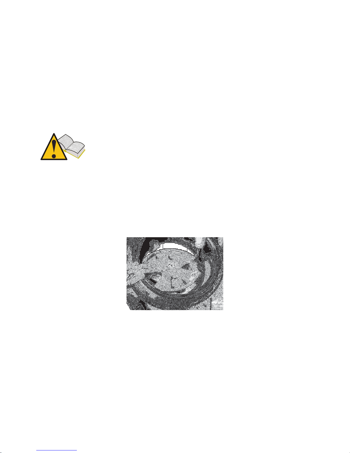
17.6. Seating the external bead
Place the sensor nearly at 9 o'clock with respect to head. These tires normally have
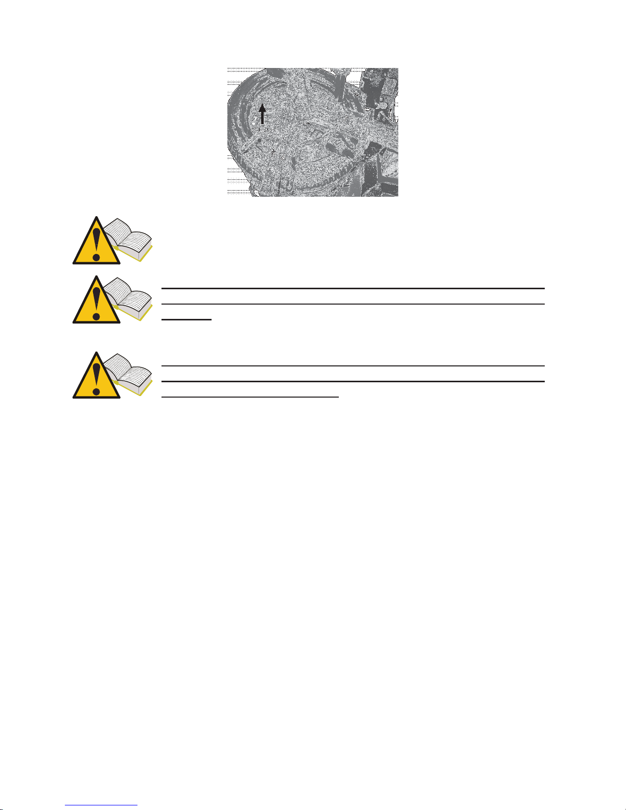
stiff sidewalls and it might be convenient to use pressure rollers (positioned as shown
in the picture) to pry the bead under the wheel well edge.
Slowly rotate the wheel until seating the bead.
Page 26
26
Follow the instructions provided by the manufacturers of tyre changer,
tire and sensor. Inflating the tire involves potential risks to operator
safety; follow the instructions of tire and sensor manufacturers.
Check sensor for proper operation before refitting the wheel to avoid
removing the wheel again in the event the sensor needs to be
replaced.
When you have installed all four wheels, check that sensors are in
the correct positions using the “Location Test” function (see
paragraph 12.5 of this manual.)
18. Hardware and software requirements for update/data
upload PC.
• Processor: > Pentium II.
• Hard Disk: > 2 GB (500MB necessary)
• Operating system: Windows 98SE or higher
• 128 MB RAM
• USB ports 1.1 or higher
• Internet access to download Sw up-dates
Page 27
27
19. UP DATING THE TOOL (PRENDERE PARTE AGGIO TPM1)
The tester needs to be updated at regular intervals in order to diagnose and display the
data of new vehicles and sensors introduced in the market.
• Connect the USB cable from the PC port to the suitable connector located at
the top of the tester.
• Power on the tester after connecting the USB cable.
• Launch the update utility you will have installed on the PC, select UPDATE
and follow the on-screen instructions.
• When finished, return the tester to its original condition and close the battery
holder.
In order to update the tester, you will need a PC with the software
supplied on the CD-ROM installed, Internet access and a
password. Obtain the password from your supplier.
The password is associated with the serial number of your tester and
the database release you want enabled.
If after updating the tester you select a vehicle and get “Vehicle
not available - Contact Service”, it means you have used a password
for an older release than that of the current database on the tester.
Contact your supplier to obtain the latest release password
Page 28

28
NOTES:_____________________________________________________________
____________________________________________________________________
____________________________________________________________________
____________________________________________________________________
____________________________________________________________________
____________________________________________________________________
____________________________________________________________________
____________________________________________________________________
____________________________________________________________________
____________________________________________________________________
____________________________________________________________________
____________________________________________________________________
____________________________________________________________________
____________________________________________________________________
____________________________________________________________________
____________________________________________________________________
____________________________________________________________________
____________________________________________________________________
____________________________________________________________________
____________________________________________________________________
____________________________________________________________________
____________________________________________________________________
Page 29

29
____________________________________________________________________
____________________________________________________________________
____________________________________________________________________
____________________________________________________________________
____________________________________________________________________
____________________________________________________________________
____________________________________________________________________
____________________________________________________________________
____________________________________________________________________
____________________________________________________________________
____________________________________________________________________
____________________________________________________________________
____________________________________________________________________
____________________________________________________________________
____________________________________________________________________
____________________________________________________________________
____________________________________________________________________
____________________________________________________________________
____________________________________________________________________
____________________________________________________________________
____________________________________________________________________
____________________________________________________________________
Page 30

30
____________________________________________________________________
____________________________________________________________________
____________________________________________________________________
____________________________________________________________________
____________________________________________________________________
____________________________________________________________________
____________________________________________________________________
____________________________________________________________________
____________________________________________________________________
____________________________________________________________________
____________________________________________________________________
____________________________________________________________________
____________________________________________________________________
____________________________________________________________________
____________________________________________________________________
____________________________________________________________________
____________________________________________________________________
____________________________________________________________________
____________________________________________________________________
____________________________________________________________________
____________________________________________________________________
____________________________________________________________________
Page 31

31
____________________________________________________________________
____________________________________________________________________
____________________________________________________________________
____________________________________________________________________
____________________________________________________________________
____________________________________________________________________
____________________________________________________________________
____________________________________________________________________
____________________________________________________________________
____________________________________________________________________
____________________________________________________________________
____________________________________________________________________
____________________________________________________________________
____________________________________________________________________
____________________________________________________________________
____________________________________________________________________
____________________________________________________________________
____________________________________________________________________
____________________________________________________________________
____________________________________________________________________
____________________________________________________________________
____________________________________________________________________
Page 32

32
____________________________________________________________________
____________________________________________________________________
____________________________________________________________________
____________________________________________________________________
____________________________________________________________________
____________________________________________________________________
____________________________________________________________________
____________________________________________________________________
____________________________________________________________________
____________________________________________________________________
____________________________________________________________________
____________________________________________________________________
____________________________________________________________________
____________________________________________________________________
________________________________________________________________
1161227-4
 Loading...