

Page 1
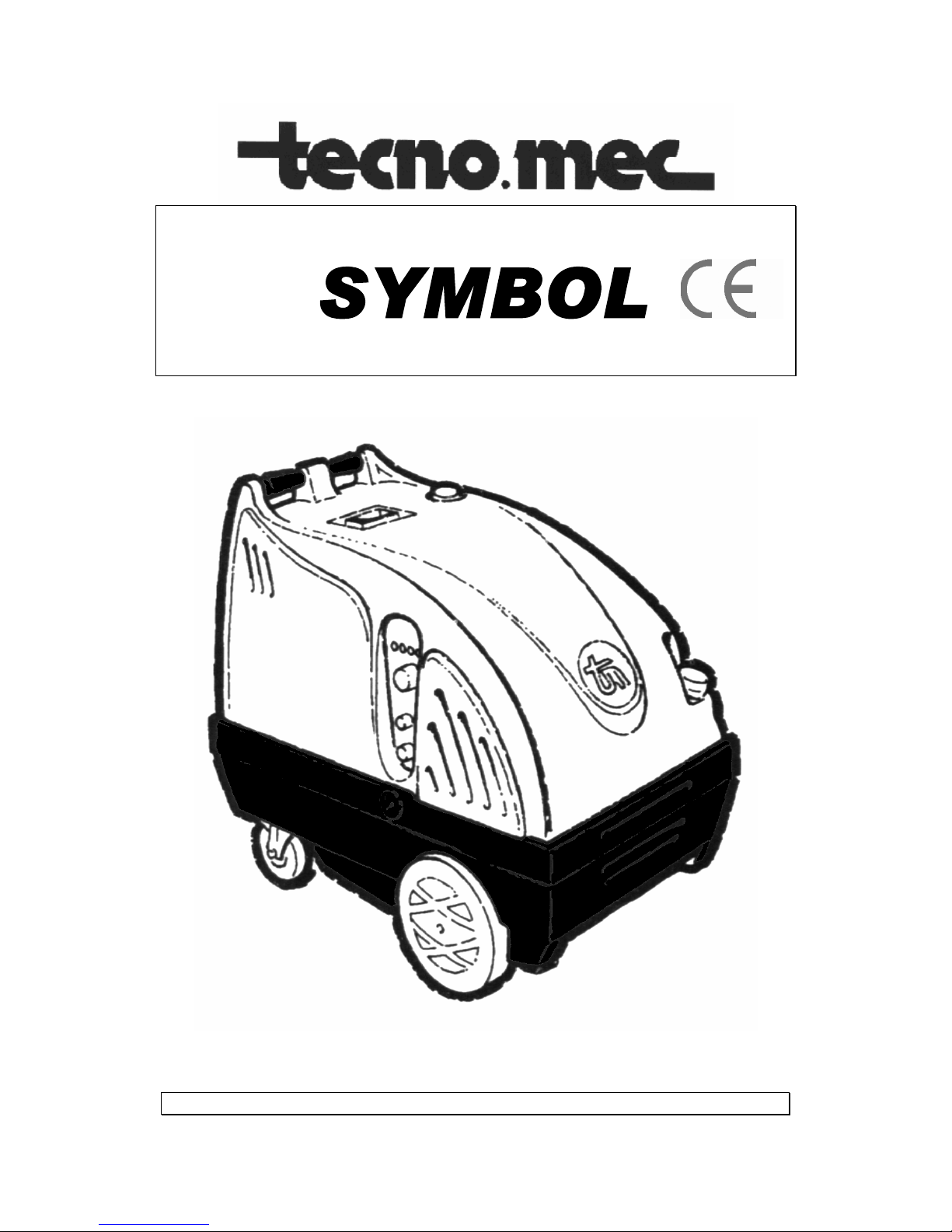
Hot water cleaner
Operating instructions
IMPORTANT: Read this booklet carefully
TECNOMEC S.r.l.
Casalgrande (RE) - Italy
Page 2

INDEX
Notice...................................................................................... page 2
Warranty regulations................................................................ page 2
Presentation............................................................................. page 3
Conditions of use...................................................................... page 3
Technical features.................................................................... page 3
General view............................................................................ page 4
Improper use............................................................................ page 5
Wrong use................................................................................ page 5
Packing and transport............................................................... page 5
Marking and identification......................................................... page 6
Conformity declaration.............................................................. page 6
Installation and starting............................................................. page 7
Normal use of the machine....................................................... page 8
Prohibited operations - safety regulations................................. page 10
Maintenance, inspections and controls...................................... page 13
Demolition of the machine........................................................ page 15
Ecological information.............................................................. page 15
Troubleshooting........................................................................ page 16
Wiring diagram......................................................................... page 17
Main internal view..................................................................... page 20
NOTICE
This handbook is an integral and essential part of the product which, as provided by directive
98/37 CE, will be consigned to the user in order to ensure the training/information for personnel.
Carefully read the notices of this handbook because they give important infomation concerning
safe installation, use and maintenance.
The manufacturer does not assume responsibility for damage caused by improper use of the
machine.
Carefully preserve this handbook for any further consultation.
Make sure of the model of your cleaner by reading the details on the identification tag on the
machine.
Upon delivery, inspect the machine for all accessories and for damage which may have
occured during transport.
Complaints will be accepted only in writing within eight (8) days from delivery.
WARRANTY REGULATIONS
1) Your SYMBOL cleaner is guaranteed against material defects for a period of six (6)
months after the date of purchase. Parts deteriorating due to normal wear (pistons,
grommets, gaskets and electrical parts) are not covered under warranty. Repairs made
by unauthorised persons invalidate the warranty.
2) Obligations of the manufacturer are restricted to replacement of defective parts.
The manufacturer makes the ultimate decision concerning the replacement or repair of
defective parts. The warranty does not cover: transport charges and risks, removal and
installation of the machine, or other charges directly or indirectly connected with repair
of the product.
3) All repairs under warranty must be made by our technicians or by an authorized aftersales service representative. Repairs made by unauthorized persons will not be
refunded.
Unauthorised repairs leading to damage of the machine are not covered under
warranty.
4) Periodical checks, calibrations, maintenance and modifications are not under warranty.
2
Page 3

HOT WATER HIGH PRESSURE CLEANER
SYMBOL
Congratulations, you have chosen a cleaner of high quality and great performance.
The SYMBOL hot water cleaner will assist you professionally for all washing, descaling,
cleaning and sandblasting purposes.
SYMBOL cleaners are recommended for use in all fields of industry, agriculture, building
industry and tourism.
SYMBOL can give you an answer to all your cleaning requirements both hobby and
professional because it is light and handy, easy to use and easy to maintain.
The large range of versions perfectly fit each kind of use.
DESCRIPTION OF THE MACHINE
SYMBOL is a cold and hot water high pressure cleaner formed by a metal chassis with wheels
and a handle for moving; generator for the production of hot water; gas-oil burner; gas-oil tank;
duct for exhaust smokes; motor-pump for inlet of pressurized water,
electric system with plug; power cable and electric board for control; cover and washing lance
with gun (or other accessories).
CONDITIONS OF USE
USE
The cleaner has been designed and manufactured for the use in car-washing, body-shops,
industries, filling stations, farms, etc.
If the machine is used in closed rooms proper aeration and a good exhaust system is
necessary to avoid the risk of poisoning. To correctly execute these instructions, please contact
our authorised technical service center.
ENVIRONMENT
The electric plant IP 54 allows to use the machine
-OUTSIDE ON SMOOTH SURFACES
-IN A DAMP ENVIRONMENT
In all cases, to assure easy and safe manual handling it is necessary for the floor to be as
smooth as possible.The machine has not been designed to be pulled or towed trained by
mechanical devices.
TECHNICAL FEATURES
Model
Max.
pressure
Capacity
Motor power
Outlet water
max. temp.
Fuel tank
Volt
(Psi) (Gp.m) (KW) (°F) (Gal.) (Volt-Hertz)
Symbol 110/11 M. 1600 2,9 2,2 285 5,2 220-50
Symbol 110/11 T. 1600 2,9 2,2 285 5,2 380-50
Symbol 150/15 2200 4 4 285 5,2 380-50
Symbol 200/15 2900 4 5,5 285 5,2 380-50
Symbol 200/21 2900 5,5 7,4 285 5,2 380-50
Symbol 150/21 2200 5,5 5,5 285 5,2 380-50
3
Page 4

GENERAL VIEW
1) Washing lance
2) Gun/hose pipe fitting
3) Quick connection
4) Water feeding hose
5) Water feeding pipe fitting
6) Electric cable
7) Detrgent tap
8) “DETERGENT” label
9) “BAR” label
10) “Technical specification plate
11) “MODEL” label
12) “EC” label
13) “Pressure gauge
14) Control board
15) Exaust smoke device
16) Detergent tank
17) “WARNING” label
18) Handles
19) Cover
20) General switch
21) Fuel tank
22) Rotating wheel with brake
4
Page 5
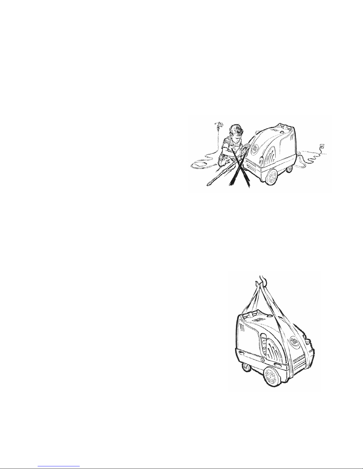
The rigorous observance of the instructions contained in this handbook is the main condition for
a safe use of the cleaner. We will not be responsible for IMPROPER OR WRONG USE of our
machines. For your information the following are examples of
dangerous behaviour.
IMPROPER USE
Improper use is using the machine in manners for which it was not designed.
- USE IN ROOMS WHERE THERE IS DANGER OF EXPLOSION OR IN WHICH THERE
IS A FIRE HAZZARD (e.g. paint stores, near petrol pumps, in deposits of material such
as wood, straw, etc.)
- USE IN CLOSED ROOMS NOT PROPERLY
AIRED
- USE IN CLOSED ROOMS WITHOUT A
CONNECTION WITH AN EXHAUST DEVICE
- USE IN THE RAIN OR DURING
THUNDERSTORMS
- USE FOR CLEANING ANIMALS
- USE BY CHILDREN
- WASHING OF ANY OBJECT CONNECTED
TO AN ELECTRICAL NETWORK
- WASHING TYRES AT A DISTANCE OF
LESS THAN 30 CM. (the tyres can be
damaged from the jet of water and could explode)
- USE IN THE PRESENCE OF PEOPLE WHO COULD BE HIT BY DIRT OR PARTICLES
AS A RESULT OF THE HIGHLY PRESSURIZED STREAM OF WATER
WRONG USE
Using the machine without following the directions contained in this handbook is considered
wrong use (see also “Forbidden Operations”). Failure to observe these directions can represent
a risk to the operator or damage to the machine. The following are examples of unauthorized
use.
- WRONG CONNECTION/USE OF STANDARD EQUIPMENT
- WRONG SUCCESSION OF STARTING INSTRUCTIONS
- THE USE OF NON-ORIGINAL SPARE PARTS
- USE OF FUEL DIFFERENT FROM GAS-OIL
- STARTING THE MACHINE WITH GAS-OIL TANK ON EMPTY
- REPAIRS MADE BY UNAUTHORIZED PERSONS
- MAINTENANCE MADE BY UNQUALIFIED PEOPLE
- USES FOR WHICH THE MACHINE HAS NOT BEEN
DESIGNED (see improper use)
- LACK OF MAINTENANCE
PACKING AND TRANSPORT
The machine is fixed to a wooden pallet and covered by a
corrugated board packaging which is fastened with a high
resistance plastic ribbon. The machine packed in this way can be
lifted also by a lift truck with forks. During shipment the container
must be protected from atmospheric agents, such as rain, fog,
sun, etc. The packed machine can be lifted by a lift truck or a
transpallet with the capcity of at least 200 Kg.
Please, verify that the capacity of the hoisting equipment is right. In case of further
transport, when it is not possible to use the original packaging, the machine must be
immobilized to avoid any shift inside the vehicle.
Put the machine on a smooth floor. When the machine is not used, store it in a room protected
from atmospheric agents.
5
Page 6
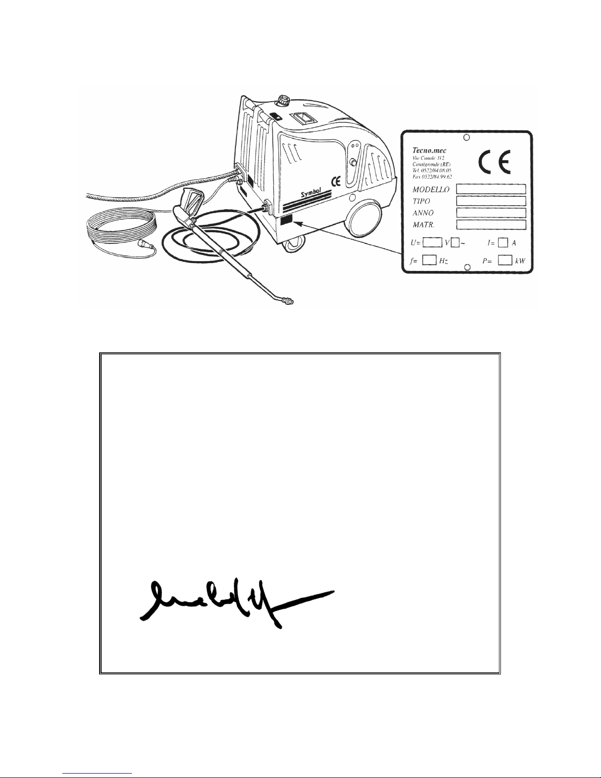
MARKING AND IDENTIFICATION
CONFORMITY DECLARATION
THE MANUFACTURER
Tecno.Mec Srl
Via Canale, 114 - Loc. Villalunga
42013 CASALGRANDE (RE) - ITALY
DECLARES THAT THE PRODUCTS:
WATER CLEANERS
SYMBOL
TO WHICH THIS DECLARATION REFERS, SATISFY THE FOLLOWING DIRECTIVES :
98/37/CE - 73/23/CEE - 89/336/CEE - 93/68/CEE
Tecno.Mec Srl
Managing director
MELIGA PIER PAOLO
6
Page 7
INSTALLATION
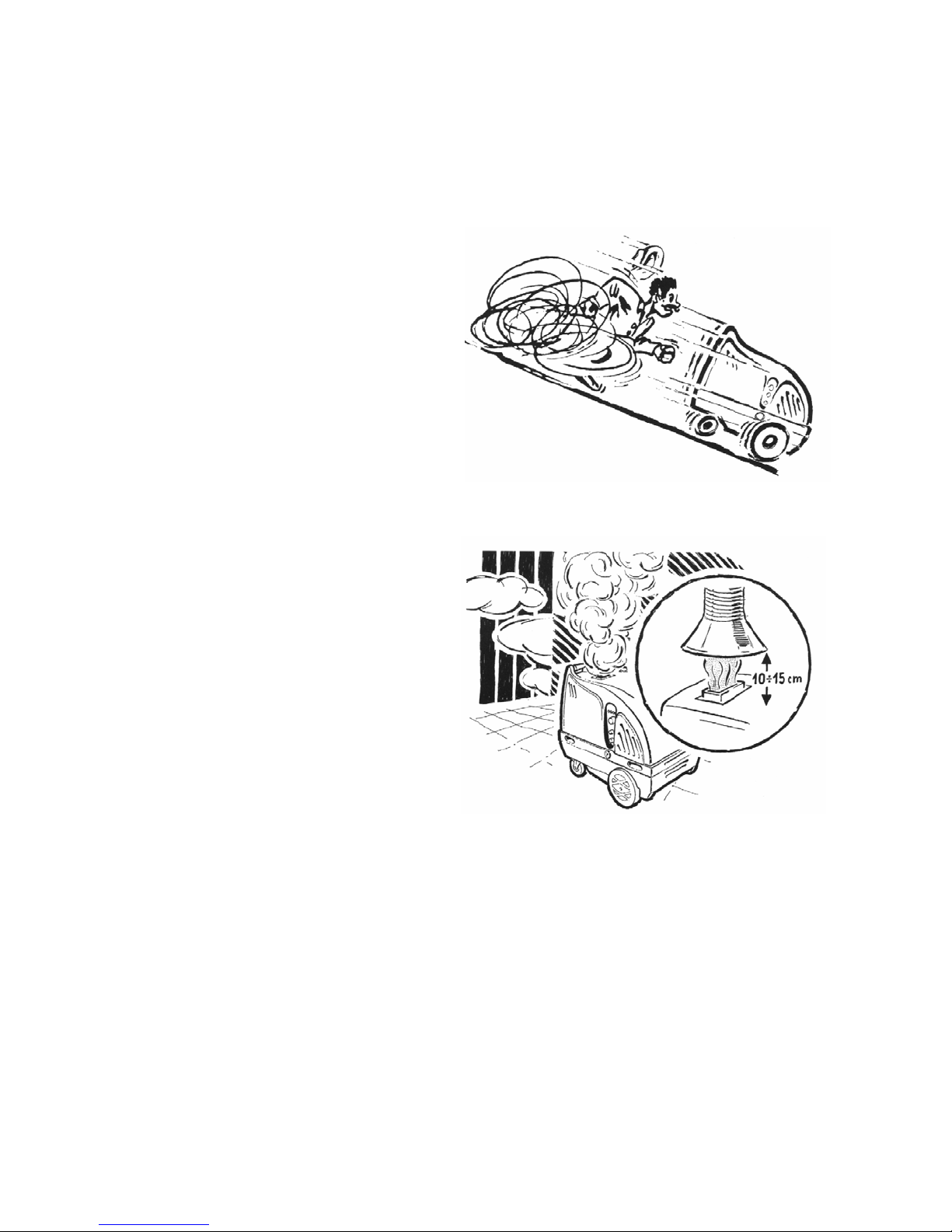
This operation must be done in clean and well-lit rooms.
1) Remove the packing carefully and inspect the machine for damage which may have occured
during transport. In case of doubt, do not use the machine
and contact the after-sales service.
The packing elements (cardboard, wood,
etc.) must be put on a suitable dump and
never left within reach of children who could
be injured.
2) Put the cleaner on a properly arranged
place, in any case on a smooth surface,
acting on the brake pedal of the rotating
wheel (FIG. B/22) block up the machine.
The work station must be equipped with:
- a current tap 400V/16A 3+PE
(230V for single-phase version)
- a water plug 1/2”, pressure 0.3 Mpa, with
an
on-off valve
- a connection to the drainage system for the
treatment of the waste water.
- Prearrange a device for the elimination of
exhaust gas as gas released in closed
rooms is dangerous, and properly air the
room.
3) Connect the water feeding hose to the
tap, this connection must be done with a
suitable flexible hose which must be as
short as possible to avoid stumbling.
4) After having unscrewed the plug (FIG.
B/21) fill the tank with diesel.
It is necessary to use clean fuel, filter it if
necessary.
5) Connect the lance (FIG. A/1) to the hose
(FIG. A/2).
Connect this one to the fitting (FIG. A/3)
6) Connect the water feeding to the quick connection (FIG. A/5) fixing it with a hose clamp. The
feeding hose must be perfectly clean inside, use a filter upstream if necessary.
7) Before doing the electric connections turn the main switch (FIG. B/20) onto OFF position and
be sure that the indications on the label (FIG. A/10) correspond to those of the electrical mains.
The installation must be done by qualified persons according to national and local rules.
8) Verify that the section of the cables, their serviceability and their capacity is suitable for the
drawn power as indicated on the rating plate.
It is important to protect the supply line using thermo-magnetic devices, coordinated with the
thermo-magnetic device of the machine. The features are indicated on the device.
9) The connection with the electrical mains must be done using taps complying with IEC 309
rule and without using extensions.
7
Page 8
10) The unit is safe only when it is correctly connected with a grounded plant and in presence of
an automatic cutout device able to grant a voltage contact not higher than 25V. Use a circuit
breaker corresponding to <=30 mA A class
WARNING: in case of a power failure the machine will stop. If it is not disconnected,
when
power is restored, the machine will start automatically.
11) Signal all the forbidden operations contained in this paragraph using the right warnings.
The execution of these operations is fundamental for the regular working of the machine.
USE OF THE MACHINE
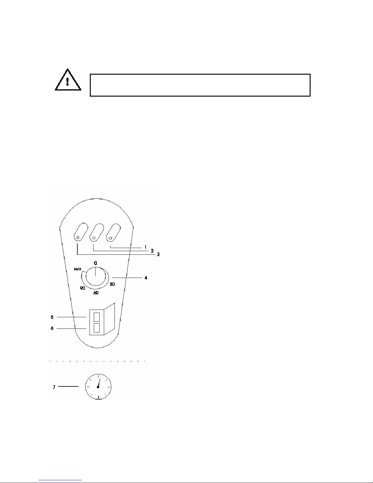
CONTROLS AND INDICATORS
1) Warning light burner lock
2) Warning light for lack of gas-oil
3) Electrical connection warning light
4) Starting knob/burner temperature
5) ON switch (green)
6) OFF switch (red)
7) Pressure gauge
Fig. C
AT THE BEGINNING OF EACH WORKING SHIFT
- Verify that the supply cable, the plug and the water
hose are in good condition. If they are damaged, do not
connect the machine to the electrical network and
contact an after-sales service center for the
replacement.
- Check that the machine does not have plain damage
- Verify that the warning lamp (FIG. C/3) on the panel of
the machine lights to indicate the presence of power.
- Verify the efficiency of the main switch
WARNING: a new machine needs the motor-pump
group to be run in. Running in consists of operating the
machine for 1 hour that wait 1 hour then waiting for it to
cool, this operation must be done 4 or 5 times.
8
Page 9
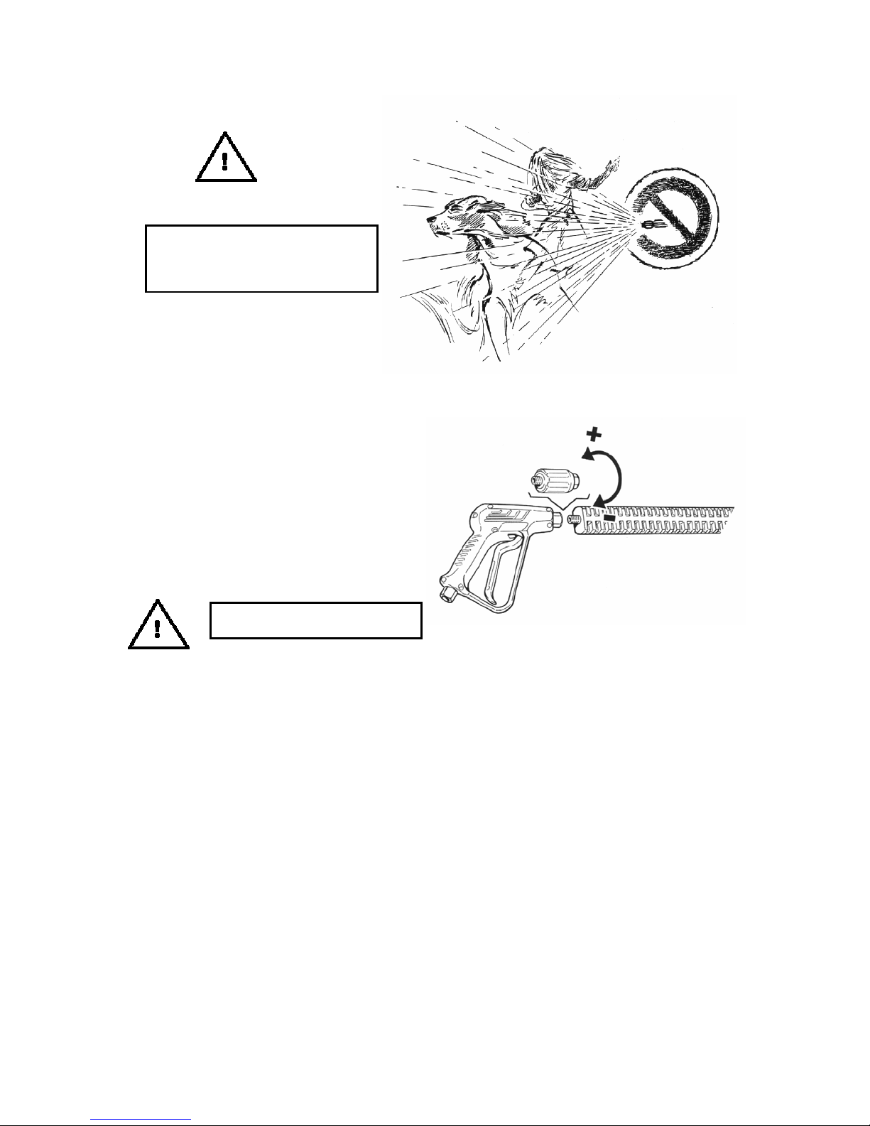
CAUTION: high pressure jet of water
. Grip the lance with both hands.
Never direct the jet of water toward
people or animals.
TO START THE MACHINE IT IS NECESSARY TO FOLLOW THE FOLLOWING SEQUENCE:
1) STARTING STAGES
A) Turn on the water
B) Set to zero the pressure by turning the
regulating knob on the lance (when
present). The pressure is indicated by
the pressure gauge (FIG. C/7)
C) Press the starting switch ON
(FIG. C/5)
CAUTION: grip the lance and the
spray gun with both hands
D) Hold the gun in the open position for a
few seconds to allow the air to escape from the hoses.
E) At this point adjust the machine to your pressure requirement by turning the pressure
regulating knob on the lance (when present)
F) Select the temperature of the water by turning the starting knob of the burner
(FIG. C/4). In position 0 the burner is OFF and water is cold
2) USE
The machine can (by low pressure or even by high pressure according to models - see table
“Equipment”) suck and mix detergents or other liquid chemicals (not corrosive) thanks to an
automatic device.
The machine is equipped with a detergent suction hose with filter (FIG. A/16)
The quantity of detergent can be regulated by turning the intake knob (FIG. A/7)
We suggest proceding in the following way:
- distribute the detergent on the surface to be cleaned
- stop the delivery and wait 3-4 minutes
- start the hot jet of water
To avoid chemical deposits building up we suggest to clean the chemical suction kit by sucking
water for a few seconds.
When the fuel inside the burner (gas-oil) reaches the minimum level, the warning light for lack of
gas-oil (2) lights up (only on prepared machines). In this case fill the gas-oil tank (FIG. B/21)
9
Page 10
If the burner does not start the warning light “burner lock” (FIG. C/1) lights up. In this case turn
the burner adjusting knob (FIG. C/4) up to 0 and wait at least 20 seconds before trying to restart
the burner.
3) SWITCHING OFF
When finished using the machine act as follows:
A) Close the spray gun
B) Turn the knob (FIG. C/4) up to 0 (burner OFF)
C) Open the spray gun and let water flow for about one minute (until the temperature lowers
and cold water comes out).
CAUTION: be sure that water is cold before stoping the machine
D) Press the OFF switch (FIG. C/6)
E) Turn off the water tap
F) Open the spray gun for a few seconds to allow the water tocome out of the hoses
G) When finished using the machine disconnect electrical and water mains and put
the machine away in a closed room.
FORBIDDEN OPERATIONS - SAFETY REGULATIONS
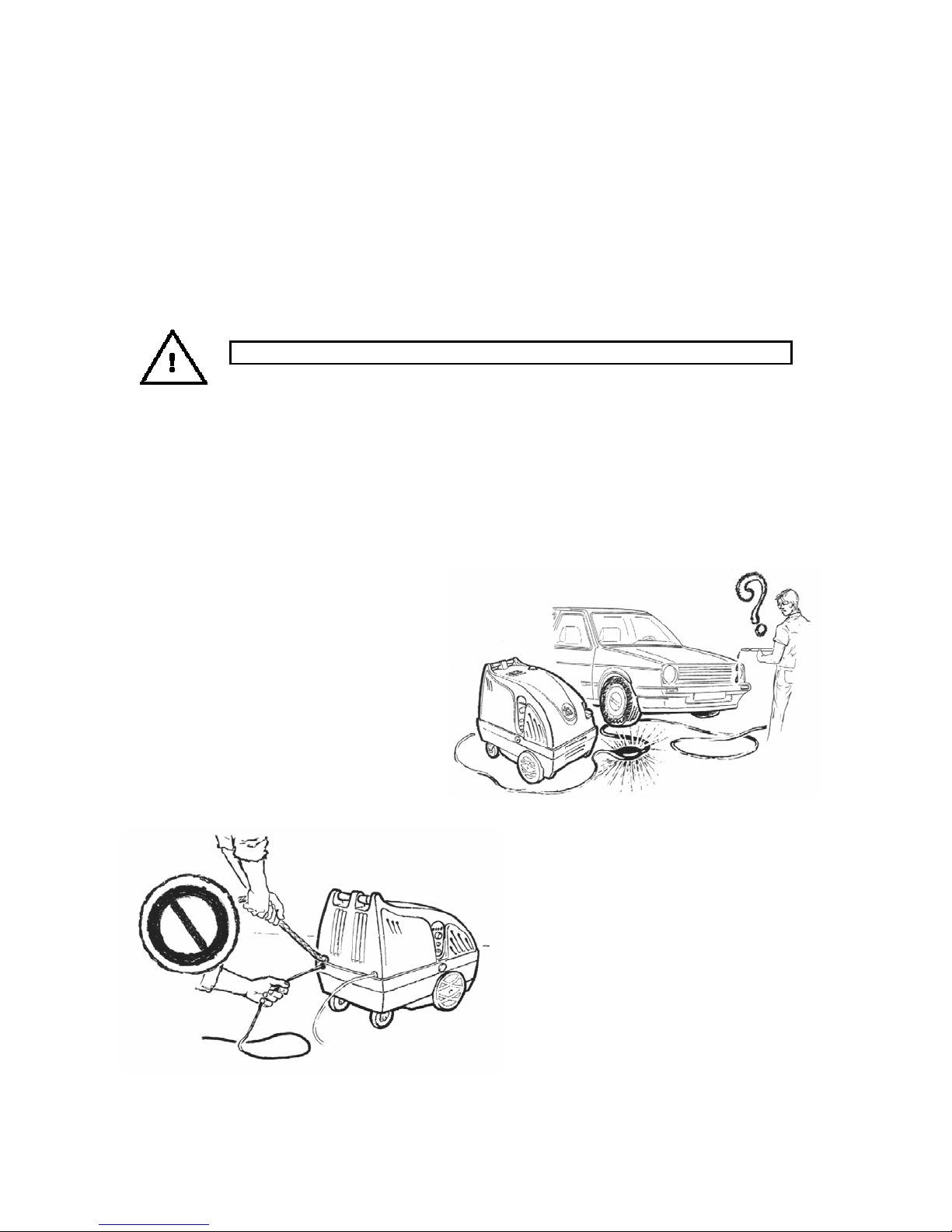
- Do not obstruct the high pressure hose,
it could explode causing damage to the
operator
- When the machine is working, never
take away the cover of the internal
equipment
- When machine is running, it generates
heat, so touch it only when it cools down
- Do not pull the machine by its electrical
cable or by the water hose
- Do not use the electrical plug to execute
the starting and switching off stages
- Do not use the machine on tilted
surfaces
- Do not use the machine bare-footed
10
Page 11
- Do not touch the exaust device until it is completely cool
- Never leave the machine unattended when it is running. In case of long stops it is
compulsory to switch it off.
- To protect against parts rebounding, it is necessary to wear protective clothes
(especially during sandblasting or descaling operations, etc.)
- If the machine is used in a danger zone (for example petrol pumps) act according to the
safety rules
- Thanks to a safety device, the
machine automatically stops if it is
inactive for more than one minute. To
use it again, it is enough to open the
spray gun
- Do not repair or adjust the working unit
before switching off the power and
disconnecting the plug from the electrical
network
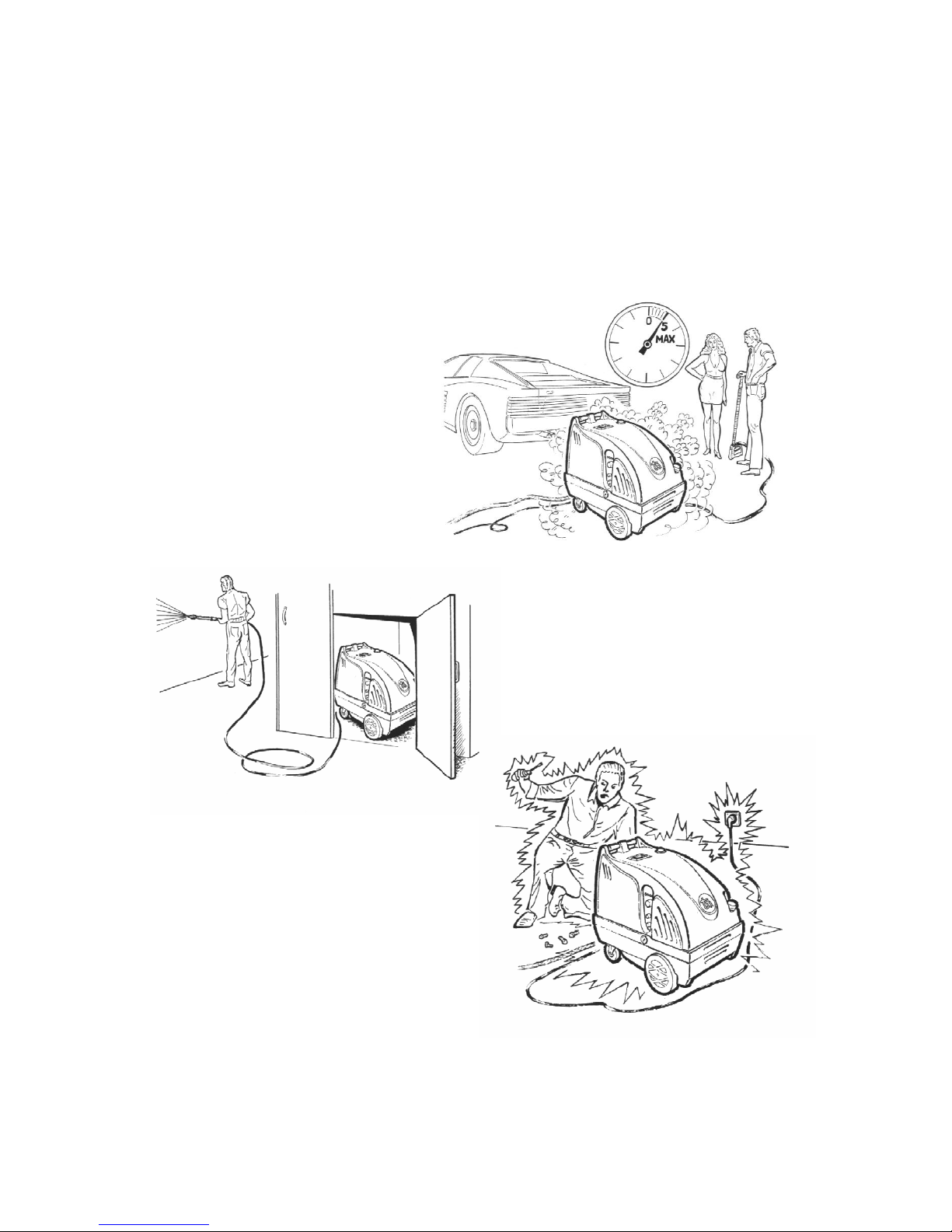
- Do not store the unit in closed rooms or
in places with insufficient ventilation. The
machine must have the possibility to blow
off gas exaust and to restore air
11
Page 12
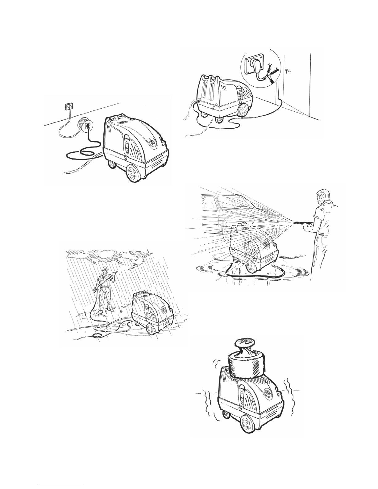
- Do not make repairs on, or do damage to
the electrical cable
- Do not direct the jet of water on the unit or
any other electrical parts and appliances.
It can damage the electrical system, it is
especially dangerous for the operator.
- Avoid using the extension, or use extensions
according to rules to avoid damages to the
operator
- Do not place heavy objects on the cover of
the machine. It could be damaged.
12
- Protect the machine from atmospheric
agents by not working with the unit in the rain
or any other situation in which liquids can
infilterate into the pump
Page 13
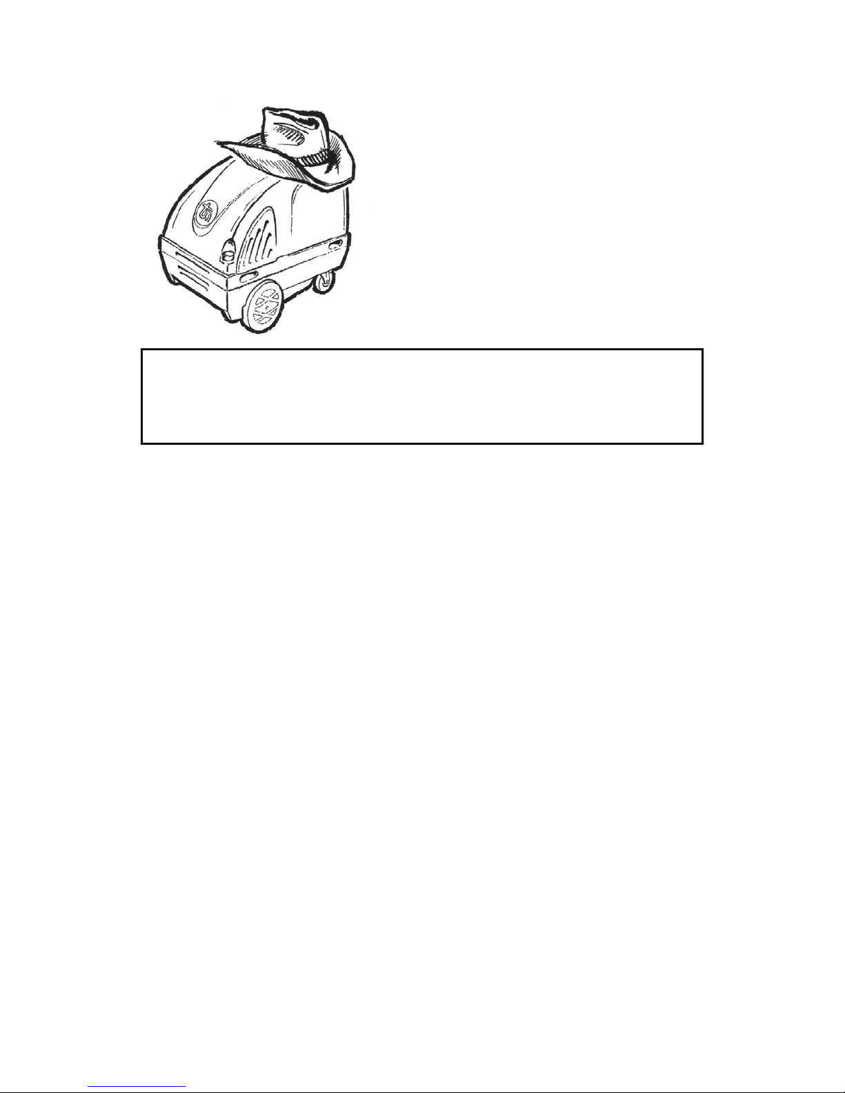
- Do not obstruct the exaust device
- Avoid using the pump without water; it could
damage the internal parts of the pump.
WARNING
If the machine is out of order or in the case of bad operation, immediately switch off the
machine by means of the main switch, and advise the qualified personnel. Switch off the
machine and disconnect the water and electrical mains and do not effect any repair.
Immediately contact qualified personnel. The repairs must be done by the manufacturer or by
an authorised after-sales center, always using original spare parts.
MAINTENANCE
The following operations must be done to avoid damage to mechanical parts and to keep your
cleaner efficient.
1) Check that the oil level is always over the dipstick cut. Change the oil after 50 working
hours, use oil type SAE 20/30. To check the oil level, unscrew the handles (FIG. A/18)
of the machine, unscrew the cap of the detergent tank (FIG. A/16) and the cap of the
gas-oil tank (FIG. B/21), then lift the cover (FIG. A/19). Now check that the oil level
inside the high pressure pump covers at least half of the oil window of the pump (or
unscrew the oil cap and verify that the oil covers the lower cut). If the quantity of oil is
not enough, do not start the machine.
2) Do not expose the unit to low temperatures. Intense cold may damage the pump and
seriously harm other circuits. In case of long stops in temperatures lower than 0°C
empty the circuits. Vice versa, high temperatures may overload the motor.
3) When the machine has been stored for a long time, there is a possibility of calcium
deposits building up. This could make instant starting difficult. In this case to avoid the
consequences of electrical over charging, before plugging the unit in, we suggest
turning the motor shaft with a screwdriver (important: disconnect the machine before
doing this operation). So you will know the cause of the locking (frost, incrustations, or
others) and you will be able to behave consequently.
4) Never intake corrosive liquids (paints, acids solvents, oily or very thick liquids) which
could permanently damage the pump. To avoid chemical deposits building up we
suggest cleaning the chemical suction kit by sucking water for a few seconds.
5) From time to time check the coil; it is enough to take off the lance nozzle and let
the pump run. Than verify that pressure on the pressure gauge does not exceed
40 bars. If it is higher, it is necessary to clean the coil as follows (IMPORTANT: on the
SYMBOL METAL the coil must be cleaned by qualified personnel):
- fill the chemical tank (FIG. A/16) with about 2 Kg. of descaling liquid
- take off the lance nozzle
- open the detergent intake regulator (FIG. A/7)
13
Page 14
- now let the pump work and open the spray gun for a few seconds to allow the
circulation of the liquid and verify it flows from the lance
- to make the descaling easier let the burner operate for about 30 seconds
- stop the machine for about 3-4 minutes
- operate the pump, open the spray gun and let all the descaling liquid flow
- close the detergent intake regulator
- rinse putting clean water into circulation
CAUTION: the descaling liquid contains acid substances which could damage the
objects to be cleaned: Be sure to have correctly rinsed them.
- carefully clean the detergent tank filling with clean water
- clean the lance nozzle and retighten it
6) From time to time check the wear of electrodes, the right distance from one end to the
other is 3 mm.
7) Replace the high pressure water hose every 2 working years or when it is necessary.
Before use verify that the pressure features of the new hose correspond to those of the
machine.
DEMOLITION OF THE MACHINE
When you decide to discard the machine it is necessary to make it inactive:
- disconnect from the electrical mains
- cut the external electric cable
- cut the motor cable
- take away the wheels
- empty the inner tanks
ECOLOGICAL INFORMATION:
The elimination of waste arising from demolition of the machine must be carried out in a manner
which does not pollute ground, water and air. Consult your local laws for more information.
DISCARDING WASTE MATERIALS:
- Ferrous materials, aluminium, copper are recyclable and must be brought to an
authorised collecting center
- Plastic materials must be carried to a proper recycling center (if one exists for such
purposes) or to a dump or burning center
- Exausted oils must be brought to an authorised collecting center.
Technical features of the product can be modified by the manufacturer at any time.
14
Page 15
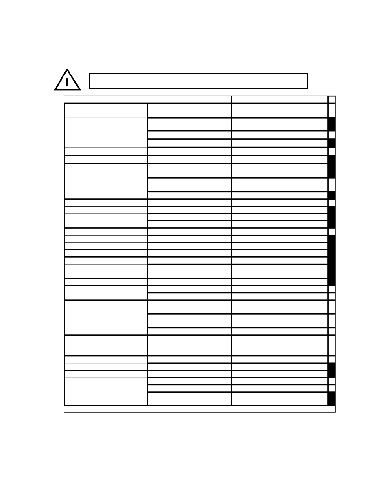
TROUBLESHOOTING
In case of operating difficulties, please check the following table. If difficulties persist, contact a
technician authorised by the manufacturer.
WARNING: Before doing any kind of maintenance, disconnect the machine from the
electric mains
FAULT CAUSE REM EDY
Pump running normally but pressure
does not achieve rated values
Fluctuating pressure Valves worn, dirty or stuck Check, clean or replace
Press ur e drops Nozzle worn Replace
Pump noisy Pump sucking air Check that hose and fittings are air tight
Presence of water in oil Pis ton pac king and oil s eal worn Check and/ or r eplace
Water dripping from pump head Piston packing worn Replace
Oil dripping Oil seal worn Replace
The motor does not start Plug not well connected Check plug, cable and switch
The motor hums but does not start The main voltage is insufficient, lower
The motor stops s uddenly Tripped thermal overload due to over
The burner does not start Lack of gas -oil
The operations marked with the black square must be done only by qualified personnel
Pump sucking air Operate the pump with open lance
Valves worn or dirty Clean or replace
Nozzle incorrect or worn Check and replace
Worn piston packing Check and replace
Cloggy suction f ilter Clean or replac e
Unloader pin valve Clean or replace
Pump sucking air Check that hoses and fittings are air tight
Worn piston packing Check and/or replace
Valves dirty Check, clean or replace
Unloader valve pin worn or locked Check and/ or repl ace
Worn piston packing Check and/or replace
Valves dirty, worn or locked Check, clean or replace
Worn bearings Check and/or replace
The O r ings of pis ton gu ide or retainer
worn
Lack of power supply Check plug, cable and switch
than the minimum required
The pump is locked or frozen Check by turning the motor manually (see
Incorrect extension cable See table INSTALLATION
heating
Electrodes worn Check (see MAINTENANCE)
Elec trodes damaged Replace
Gas-oil filter obstructed Replace
Gas -oil nozzle obs truc ted Clean the burner nozzle
Fuse of the motor burner and
transformer damaged Replace
Replace
Check that the mains power supply is
adequate
ADVICE)
Chec k that the main voltage correspond to
the specifications.Switch off the motor and
let it cool for a few minutes
Check the gas-oil level and the f loat
15
Page 16
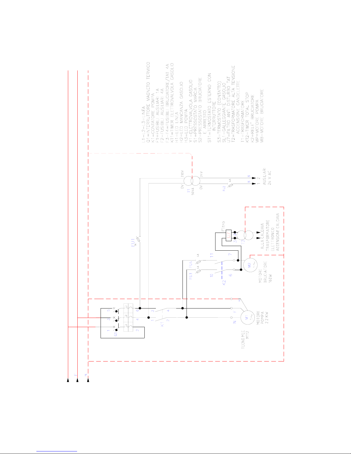
WIRING DIAGRAM - SYMBOL SINGLE-PHASE
(SYMBOL 11/110M)
16
Page 17
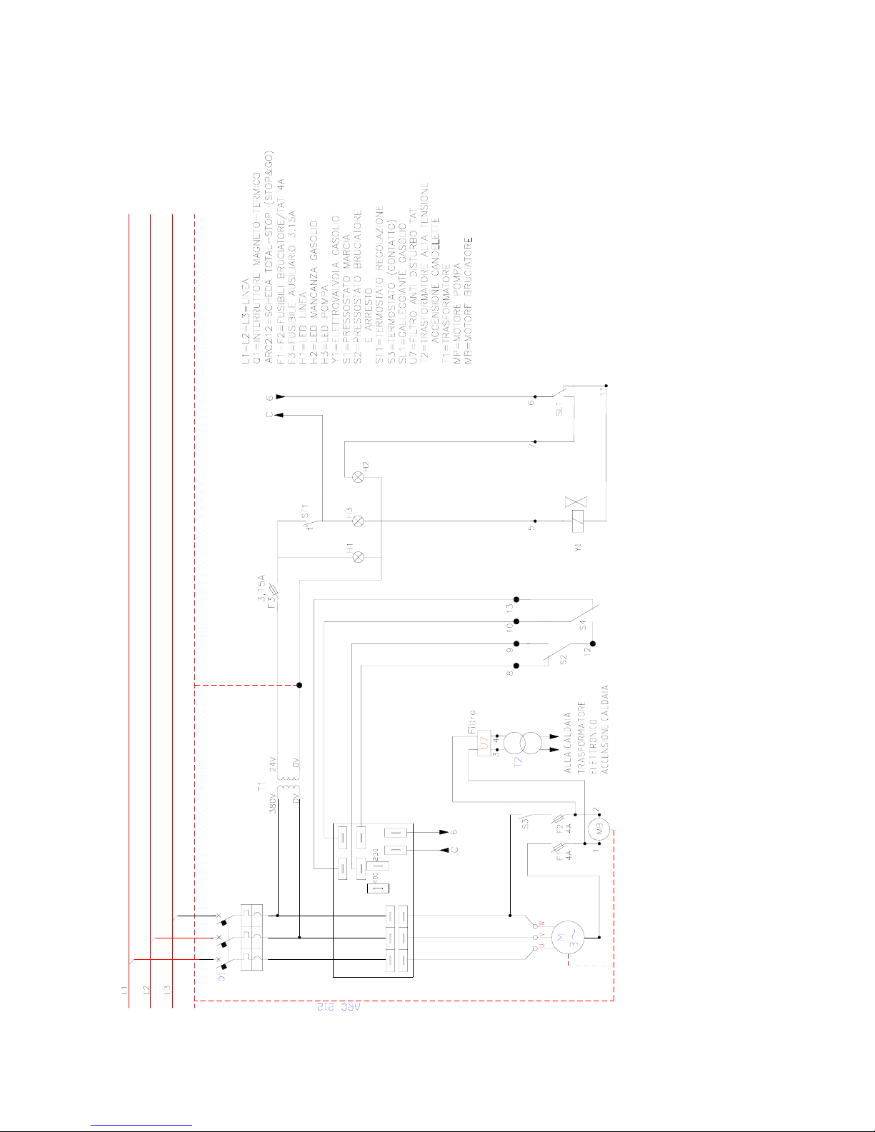
WIRING DIAGRAM - SYMBOL THREE-PHASE “A” VERSION (STANDARD)
(SYMBOL 11/110T – 15/150 – 13/170)
17
Page 18
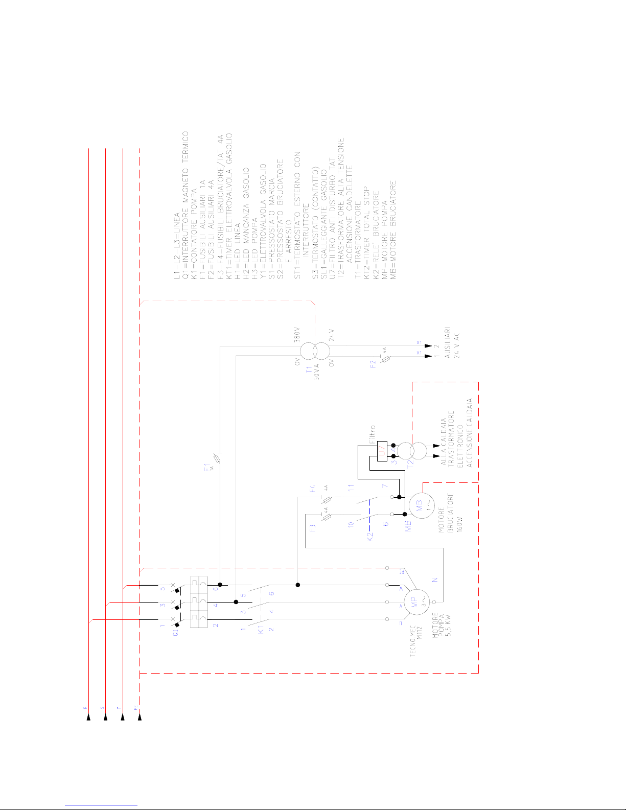
WIRING DIAGRAM - SYMBOL THREE-PHASE “B” VERSION
(SYMBOL 15/200- 21/200 - 21/150)
18
Page 19
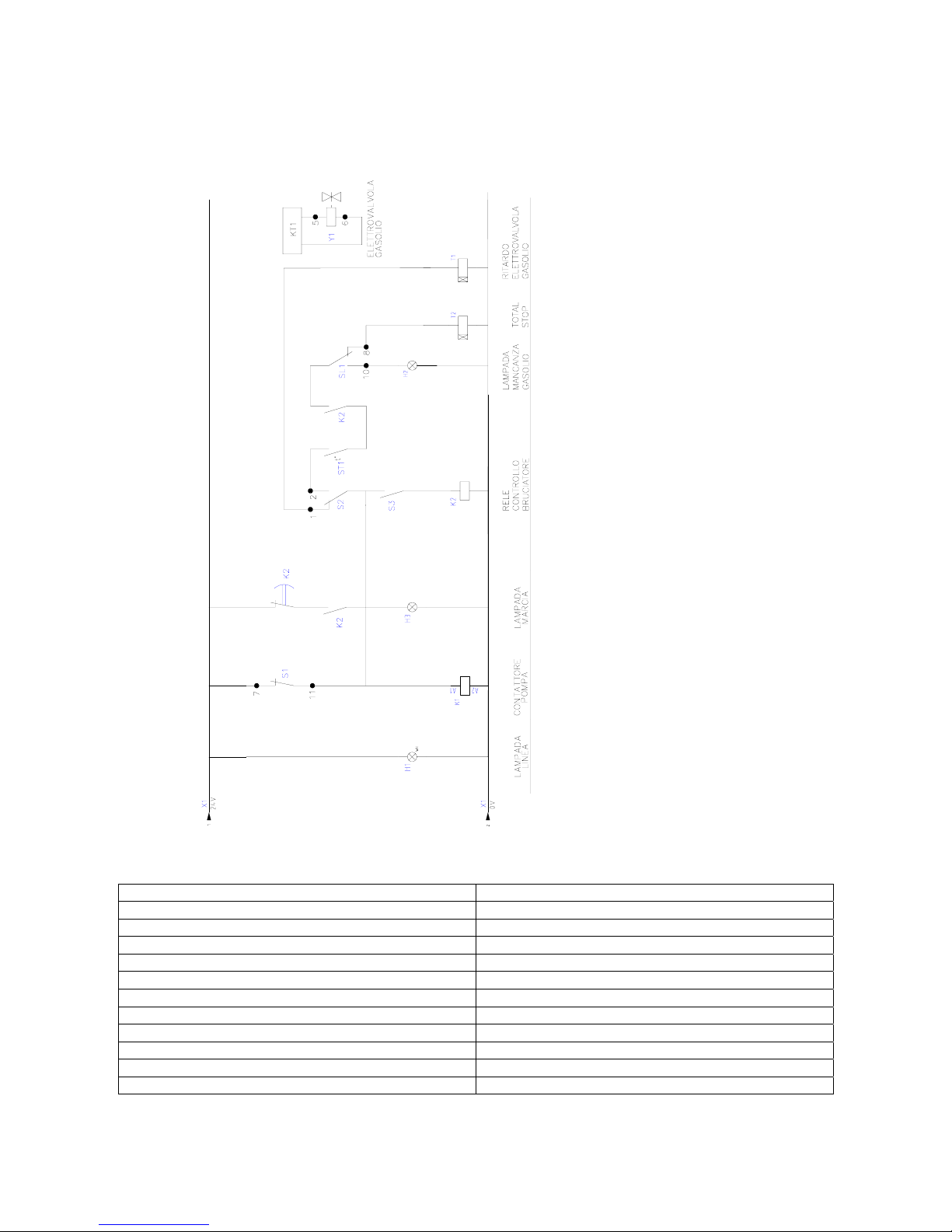
AUXILIARY WIRING DIAGRAM
(ALL VERSIONS)
WIRING DIAGRAMS LIST
L1 – L2 – L3 = LINE SL1 = GAS OIL FLOAT
Q1 = MAIN SWITCH S1 = PRESSURE SWITCH (run)
K1 = PUMP SWITCH S2 = PRESSURE SWITCH (burner)
F1 = FUSE 1A ST1 = EXTERNAL THERMOSTAT with SWITCH
F2 = FUSE 4A S3 = THERMOSTAT (contact)
F3-F4 = FUSE BURNER/TAT 4A K2 = BURNER RELAY
Y1 = GAS OIL SOLENOID VALVE KT2 = TOTAL STOP TIMER
KT1 = GASOIL SOLENOID VALVE TIMER T2 = HIGH VOLTAGE TRANSFORMER
H1 = LINE LED T1 = TRANSFORMER
H2 = GAS OIL LACK LED MP = MOTORE POMPA
H3 = PUMP LED MB = MOTORE BRUCIATORE
U7 = ANTINOISE TAT FILTER ARC212 = TOTAL STOP DEVICE
19
Page 20
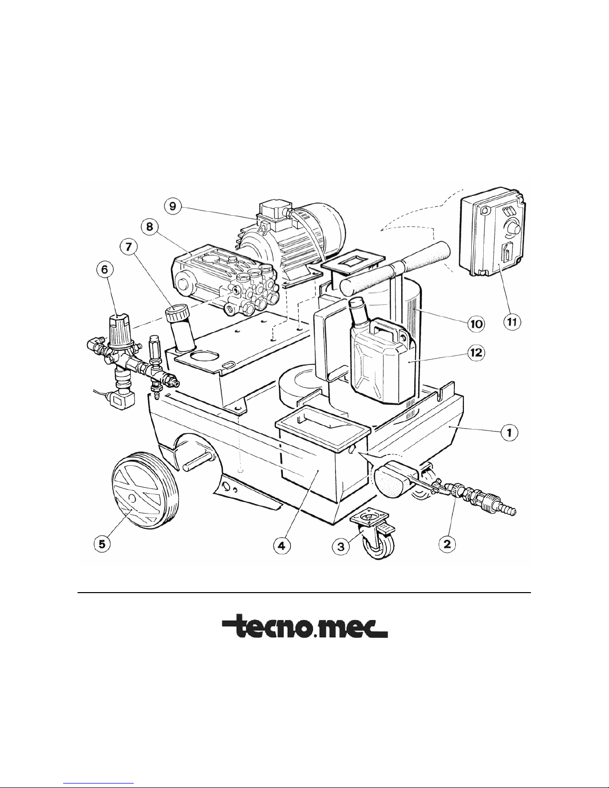
MAIN INTERNAL VIEW
1) Chassis 5) Fixed wheel 9) Electric motor
2) Float 6) Vlave group 10) Boiler
3) Rotating wheel 7) Fuel tank 11) Control board
4) Water tank 8) High pressure pump 12) Detergent tank
Via Canale, 114 - 42013 CASALGRANDE (RE) - ITALY
Tel. +39-0522-840805 Fax +39-0522-849962
rev. 2/2002
Internet: http://www.tecnomec.com
20
 Loading...