

TECNOMAGNETE ST100 Series, ST100F, ST200 Series, ST100R, ST200F Instruction And Maintenance Manual
Sistema elettronico di controllo per piani magnetici
Electronic control system for magnetic chucks
Système électronique de commande pour des plateaux magnétiques
Elektronisches Steuersystem für Magnetplatten
Sistema electrónico de control para planos magnéticos
ST100
Manuale uso e manutenzione
Instruction and maintenance manual
Manuel d’utilisation et d’entretien
Betriebs- und Wartungsanleitung
Manual de uso y mantenimiento
ITALIANO
ENGLISHFRANÇAISDEUTSCHESPAÑOL
ST200
Nr. 50 100 7816

INDEX
1
GENERAL NOTES .................................32
1.1
Overview of the company...........................32
1.2
Importance of the manual ..........................33
1.3
Storing the manual .....................................33
1.4
Conventions ...............................................33
1.5
Denition of symbols .................................33
1.6
Personnel responsible for operations ........33
1.7
Trained personal .........................................34
1.8
Individual protection means .......................34
1.9
General safety precautions.........................34
1.10
Behavior during emergency situations ......34
1.11
Limitations ..................................................34
1.12
Improper or non permitted use ..................35
1.13
Nameplate data ..........................................35
2
TRANSPORTATION AND
HANDLING .............................................. 36
2.1
Receipt .......................................................36
2.2
Handling .....................................................36
2.3
Transportation ............................................36
2.4
Storage ......................................................36
3
DESCRIPTION OF THE SYSTEM ......37
3.1
Description of the controllers ..................... 37
3.2
Model ST100X ............................................37
3.3
Model ST200X ............................................38
3.4
Control push-buttons for ST controllers ....39
Page
8
CONNECTION TO
TECNOMAGNETE MODULE
8.1
Installation of miller ST100 .........................48
8.2
Installation of grinder ST100 ......................48
8.3
Installation of miller ST200 .........................49
8.4
Installation of grinder ST200 ......................50
9
ORDINARY USE .....................................51
9.1
ST100 .........................................................51
9.2
ST200 ........................................................51
10
ANALYSIS OF RESIDUAL RISKS ......52
11
MAINTENANCE .....................................52
11.1
Premise ......................................................52
11.2
Maintenance safety instructions.................52
11.3
Weekly maintenance ..................................53
11.4
Monthly maintenance ................................53
11.5
Maintenance to be carried out every
six months ..................................................53
11.6
Extraordinary maintenance.........................53
11.7
Information on extraordinary reparation
and maintenance ........................................ 53
12
TROUBLESHOOTING AND
CORRECTIVE ACTIONS ......................54
Page
.............48
ENGLISH
4
INSTALLATION ......................................43
4.1
General .......................................................43
4.2
Connecting ST100 controllers to the
power supply .............................................44
4.3
Connecting ST200 controllers to the
power supply ..............................................44
5
ENABLING ..............................................45
5.1
ST100 .........................................................45
5.2
ST200 .........................................................45
6
OPTIONAL COMPONENTS ...............46
6.1
Starting the ST100 controller .....................46
6.2
Push-button panels of models ST100
and ST200 ..................................................46
6.3
QE version ..................................................46
7
PLC ...........................................................46
Instruction and maintenance manual
13
DECOMMISSIONING AND
DISPOSAL ...............................................54
13.1
Decommissioning ......................................54
13.2
Dismantling ................................................54
14
WARRANTY AND TECHNICAL
SUPPORT ................................................55
14.1
Warranty terms and conditions ..................55
14.2
Invalidity of warranty ..................................55
15
TECHNICAL SUPPORT SERVICE ....56
DELARATION OF
CONFORMITY .......................................57
Edition: 07-12
Replaces: 03-09
31

1
GENERAL NOTES &
1.1 Overview of the company
Thank you for purchasing one of the many products
manufactured by TECNOMAGNETE S.p.A.
This manual is designed to help you become familiar
with your new product and must therefore be carefully read and followed.
For further information on the system, you can contact TECNOMAGNETE’s technical support at any
time.
The descriptions and illustrations provided in this
manual are for reference only.
While conrming the general characteristics
ENGLISH
of the controllers described in the manual,
TECNOMAGNETE S.p.A. reserves the right, at its
discretion, to change at any time some of the characteristics in order to improve the product or due to
manufacturing and commercial reasons. The necessary updates, if required, shall be supplied as attachments.
This manual is property of TECNOMAGNETE S.p.A.
and cannot be copied in whole or in part or made
available to third parties without the written authorization of the manufacturer. Should the products be
amended and/or updated, upon authorization of
TECNOMAGNETE S.p.A., the manufacturer shall
integrate the existing manual by providing the text
explaining the use of the modied/integrated component along with a description of potential residual
risks.
TECNOMAGNETE started its activities in 1972 as
manufacturer of permanent-electro magnetic systems designed to ensure power, exibility and maximum safety. Its state-of-the-art technologies and the
patents developed over the years have enabled the
company to become a leading supplier in several
international markets.
The permanent-electro magnetic systems manufactured by TECNOMAGNETE are able to produce all
the magnetic force required both to clamp and lift
work pieces, thus eliminating the need of using electric power during machining.
Its main elds of activity include:
CLAMPING SECTION FOR LIFTING
•
MTE permanent-electro lifters designed to ena-
ble the handling of ferrous loads of any shape and
dimension.
•
BAT-GRIP permanent-electro lifters with incor-
porated battery.
•
MaxX manual lifters.
WORK HOLDING LINE
•
QUADSYSTEM chucks for millers and machining
centers of all sizes.
•
TFP0 and TFP1 for high precision grinding.
•
RADIAL-POLE chucks for nishing or roughing
operations on boring mills.
•
QUAD-RAIL modules to clamp rails of varying
lengths.
•
MDS chucks for EDM machines.
32
STAMPING and MOLDING LINE
•
QUAD-PRESS systems to clamp molds.
TECNOMAGNETE has installed approximately
50,000 units in over twenty years, thanks mainly to
its wide-ranging offer, its exibility to meet customers’ requirements and its efcient post-sales service.
Instruction and maintenance manual
1.2 Importance of the manual
1.5 Definition of symbols
A copy of this manual must always be made available to the operators responsible for the installation,
operation and maintenance of the controller in order
to allow them to carry out all the required operations
in compliance with the instructions provided in the
manual.
A full compliance with the instructions provided in
this manual is an essential requirement to be able to
correctly use the equipment and ensure the safety of
operators and other people.
The manual forms integral part of the controller.
Therefore, all reproduction and divulgation rights related to the manual or its exhibits are reserved.
The manual must always be transferred to the new
owner of the machine if the latter is sold.
1.3 Storing the manual
It is severely forbidden to remove parts, tear pages
or alter this manual.
The manual should always be carefully preserved so
that it is not damaged.
Always protect the manual from excessive humidity
and heat and store it in a location where it can be
easily accessed by operators in case of need.
1.4 Conventions
To simplify consultation, the manual has been divided into the following hierarchical order so that each
phase is described in detail:
1 Section 1 of the manual.
1.1 Chapter 1 of Section 1 of the manual.
1.1.1 Paragraph 1 of Chapter 1 of Section 1 of
1.1.1.1 Subparagraph 1 of paragraph 1 of Chap-
Some chapters and/or sections contain bulleted lists
to allow operators to follow the operation described
step by step.
Parts that require specic attention are highlighted
with symbols.
Instruction and maintenance manual
the manual.
ter 1 of Section 1 of the manual.
All information related to safety is highlighted in bold.
All warnings that draw the attention of operators on
operations that may be hazardous in terms of safety
or health or that may cause physical injuries, if the
applicable instructions are not followed, are highlighted in red and marked with the following symbol:
All warnings related to operations that have to be
carried out by skilled and qualied personnel are
highlighted in bold and marked with the following
symbol:
1.6 Personnel responsible for operations
Some operations, as stated in this manual, can only
be performed by qualied and skilled personnel. The
qualication level is described by means of the following standard denitions:
•
Qualied personnel is personnel with specic
technical knowledge and/or the experience necessary to avoid potential risks originating from
power supply (engineers and technicians).
•
Trained staff is personnel that operates following
the instructions and/or under the supervision of
qualied personnel, who is responsible for verifying that they are not exposed to potential hazards
resulting from the contact with power (personnel
responsible for operation and maintenance). This
personnel must have the following qualications:
1. All personnel must be trained and authorized to
disconnect the machine from the power supply, to
connect it to the grounding system and to mark
circuits and equipment following standard safety
procedures.
2. All personnel must have been specically trained
to follow correct maintenance procedures and
use the protective equipment in accordance with
standard safety procedures.
•
Before using the unit, users shall always have to
verify with authorized personnel that:
1. All personnel has received a copy, has read and
understood the content of the instruction manual.
2. All personnel has agreed to follow the instructions
provided.
33
ENGLISH
1.7 Trained personal
•
OPERATORS: workers who, after receiving the
necessary instructions, have been authorized by
the owner to operate the controller and the equipment connected to it. Workers with this qualication must be thoroughly familiar with the content
of this manual.
•
ELECTRIC MAINTENANCE TECHNICIAN (ref.
EN60204 paragraph 3.45): this qualication is assigned to all personnel specically trained to perform operation on electric components, which include connections, adjustments, maintenance
and/or reparations, and to personnel who is qualied to perform operations inside electric cubicles
ENGLISH
and boards. This qualication implies having a
perfect knowledge and full familiarity with the
content of this manual.
All operators are therefore expected to follow the
instructions below and to thoroughly comply with
the safety procedures concerning the installation
and use of the equipment applicable in the country in which the unit is used.
All ordinary and extraordinary maintenance operations shall have to be carried only after the
unit has been disconnected from the power supply.
Before connecting the power cable, it is essential
to verify that the line voltage complies with the
one shown on the nameplate of the controller.
All transportation, installation, ordinary and extraordinary maintenance operations performed
on the controller must be carried out only by personnel with the qualifications stated in Chapter
1.6 and 1.7.
1.8 Individual protection means
The personnel referred to in the paragraph above
must always wear suitable protective clothing
and use the protection means generally required
to operate the tool machine on which the Tecnomagnete module and controller are installed.
In particular, personnel shall always have to wear
industrial shoes along with ear protection, helmets and goggles, if required.
All personnel should refrain from wearing loose
clothing that could get tangled with moving components.
1.9 General safety precautions
The instructions and recommendations provided
below comply with current safety regulations and
imply the obligation of complying with applicable
provisions.
TECNOMAGNETE S.p.A. shall not be responsible
for damages caused to people or equipment
originating from the failure to follow applicable
safety provisions and to comply with the instructions given below.
1.10 Behavior during emergency situations
In the event of emergency, it is always advisable
to follow the procedures outlined in the operation
and maintenance manual of the machine on
which the controller is installed.
In the event of fire, always use the extinguishing
means provided being careful not to use water to
extinguish fires on electric parts.
1.11 Limitations
The unit can be used only for the applications
specified in operating instructions and only in
combination with the equipment and components recommended by TECNOMAGNETE S.p.A.
34
Instruction and maintenance manual
1.12 Improper or non permitted use
The controller is not designed and has not been
manufactured to be used in explosive environments.
An improper use may:
•
Cause injuries to personnel.
•
Damage the controller or any other equipment
connected to it.
•
Affect the reliability and performance of the
controller.
In particular, it is essential to adhere to the following instructions:
•
Always use suitable working parameters.
•
Carry out the required maintenance in accord-
ance with the instructions provided.
•
Use suitable equipment.
•
Comply with all the instructions provided.
•
Fix the unit onto a stable surface.
•
Contact TECNOMAGNETE S.p.A. in case of
doubt to determine whether a specific operation is permitted.
1.13 Nameplate data
ENGLISH
The controller is tted with an identication label in
compliance with current laws.
ATTENTION
The nameplate should never be removed even if
the unit is resold.
If the nameplate is damaged or has been
removed, it is necessary to contact
TECNOMAGNETE S.p.A. to order a duplicate.
Always quote the model printed on the
nameplate in all communications with
TECNOMAGNETE S.p.A.
Failure to comply with the above instructions
shall entitle TECNOMAGNETE S.p.A. to disclaim
any responsibility for injuries to personnel and
damage to equipment, making the user fully responsible before competent authorities.
Instruction and maintenance manual
35
2
TRANSPORTATION AND
HANDLING
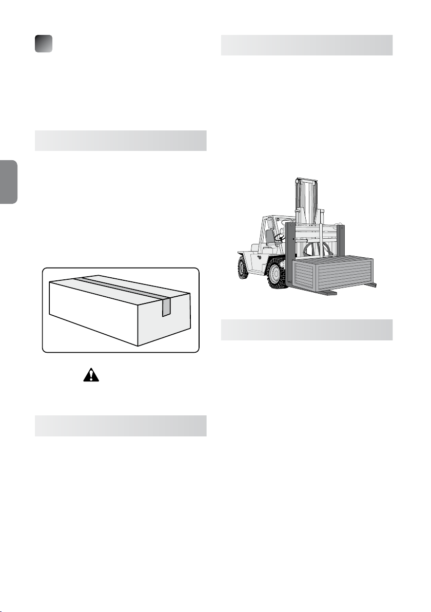
The unit is shipped in a cardboard box, covered with
a plastic sheet and enveloped by polyurethane foam
to protect it from damage in the event of impacts or
accidents.
2.1 Receipt
All units are carefully inspected before shipping.
Upon receipt, customers should verify that the
packaging and the material inside it has not
been damaged (unless otherwise instructed by
ENGLISH
TECNOMAGNETE S.p.A.) in order to ensure that the
unit has not been damaged during transport and that
the material supplied complies with order specications. Visible transport damages should be immediately reported to TECNOMAGNETE S.p.A. and the
forwarding agent.
ATTENTION
All damages and anomalies must be reported within
ten days from receiving the goods.
2.2 Handling
Weight of model ST100: 0,4 kg.
Weight of model ST200: 2,0 kg.
Always keep the original packaging so that it can
be used to transport the unit if needed.
2.3 Transportation
The unit should always be transported within the following environmental limits: temperature ranging
from –10°C to +55°C, with temperature increase up
to 70°C for a maximum of 24 hours.
If the unit requires the use of specic transportation
means (by sea or air), special provisions shall have to
be adopted in order to protect it from damages
caused by potential impacts. The box should also
contain hygroscopic salts to protect the unit from
atmospheric agents.
2.4 Storage
The unit should always be throughly cleaned and
adequately protected when stored for long periods
of time.
Disconnect the controller from the magnetic chuck
and from the power supply.
It is generally advisable to cover the unit with a waterproof bag and store it in dry and safe place.
The temperature of the storage area should range
between 0°C (32°F) and 55°C (131°F).
Relativy humidity should be between 30% and 90%,
non condensing.
The atmosphere should be clean, free from acids,
corrosive gases, salts, etc
When restarting the machine, always follow the instructions provided in Chapter 4.
36
Instruction and maintenance manual
3
DESCRIPTION
OF THE SYSTEM
3.1 Description of the controllers
ST is an innovative electronic controller for
networked chucks designed for milling and grin-
ding operations.
The sections that follow provide information on the
size and the basic characteristics of the available
models:
•
ST100F (milling)
•
ST100R (grinding)
•
ST200F (milling)
•
ST200R (grinding)
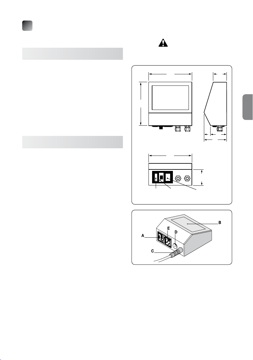
3.2 Model ST100X
The rated operating voltage is 230V.
The control push-button panel is integrated in to the
controller.
The control electronics are situated under the control
push-button panel and enclosed in a plastic housing.
To simplify installation and facilitate the reading of
the push-button panel, it is also possible to install
the controller on a workbench or mount it on the wall
by simply rotating the control panel.
The plastic material of the housing ensures a high
level of insulation and the utmost safety during use.
The rear part of the controller has a block with a male
pin (designed to be connected to the power cable),
an ON–OFF (0-1) switch and a fuse-holder with two
12.5A protection fuses (type 5x20 mm). Two or more
cable ties for the output of the discharge cables of
the chucks to be magnetized may be present next to
these components.
The maximum useful current that ows into the
ST100X controller is approximately 12.5A; the current supplied to the module is impulsive with a cycle
time around a few hundreds of milliseconds (app. 1
second per discharge).
ST100X controllers are suitable to control small
chucks with a single phase voltage of 230V and a
maximum absorption of rated current of 3kW.
For different rated voltages, use a transformer with a
suitable transformation ratio and a rating suitable to
handle the maximum power of the chuck or at any
Instruction and maintenance manual
rate a maximum power of 4kVA. For example, if the
available voltage is 400V, a transformer with a
400/230 transformation ratio is required.
ATTENTION!
Control units can be moved only
when controls are not powered.
135
135
Rear
135
Fuse-holder Main Power supply
switch input
40
50
75
40
MAIN PARTS
A ➜ Main switch
B ➜ Push-button panel
C ➜ Discharge cable output
D ➜ Start contact
E ➜ Power supply input
37
ENGLISH
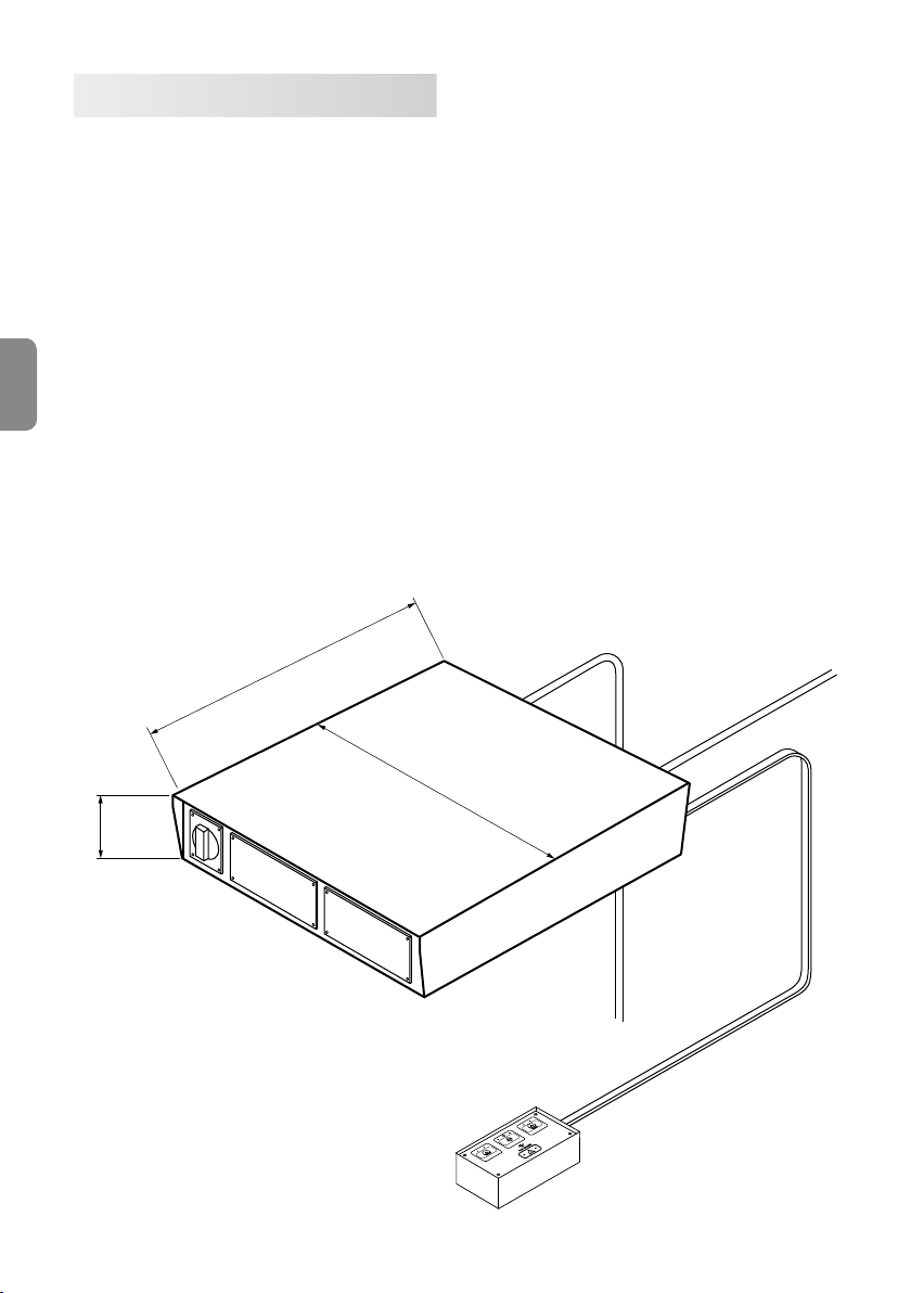
3.3 Model ST200X
The rated operating voltage of this controller varies
according to the type of magnetic chuck to which it
is connected.
The control push-button is external, but can also be
integrated into the controller.
The control electronics are enclosed in a metal housing. The metal material of the housing is grounded in
order to guarantee maximum safety during the enabling cycles.
It is important to verify that the grounding system is
always in good working order.
The controller does not have a socket for the connection to the power supply. The controller has an
ENGLISH
ON–OFF (0-1) switch, thus to adequately protect it
against short circuits, it is necessary to install a suitable protection system upstream from the controller.
It is generally advisable to use a magneto thermal
switch (curve C) with an In value compliant with the
rating specied on the magnetic chuck nameplate
that will be connected to the controller.
275
The maximum power of controller ST200X is approximately 25kW per discharge if the single phase
power supply is 400V, 15kW for power supplies of
230V and 30kW for power supplies of 480V. The absorbed current is impulsive with a cycle time around
a few hundreds of milliseconds (approximately 1
second per discharge).
ST200X controllers are suitable to power single
chucks or chucks that are part of large magnetic
banks
When using chucks with a different rated voltage,
install a transformer with a suitable transformation
ratio and a rated power that matches the maximum
power of the chuck.
It is also possible to order a compact version for
ST200-QE electric cabinets with supporting terminal
board, to power the controller and magnetic chuck,
with interface connector and push-button panel.
38
331
85
Instruction and maintenance manual

3.4 Control push-buttons for ST controllers
ST controllers can be connected to the push-button
panels described below.
3.4.1 ST100 (basic version),
ST200 (basic version)
This push-button panel is the base model used to
control milling chucks.
It is tted with the following three-buttons:
•
Magnetization FULL-MAG,
•
Demagnetization DEMAG,
•
Enabling ENABLE.
The ENABLE button is used together with the magnetization and demagnetization button, depending
on the cycle that needs to be performed.
There are also 4 indicator lights placed next to the
FULL-MAG and DEMAG buttons and the CYCLE
and ALARM symbols.
These indicator lights provide information on the status of the controller. When the controller is started,
the corresponding LED indicator switches on.
If a cycle is active, the only LED that is on is the one
related to the cycle, while all the others are off.
At the end of the cycle, the only visual indication that
is on is the one related to the new system status.
D
A C
B
PUSH-BUTTON PANEL
A
➜ FULL-MAG button
B
➜ ENABLE button
C
➜ DEMAG button
D
➜ MAG led
E
➜ Cycle led
F
➜ DEMAG led
G
➜ Alarm status led
E
G
F
ENGLISH
System status MAG Led DEMAG Led Cycle Led Alarm Led
Full-Mag Permanently on Off Off Off
Demag Off Permanently on Off Off
Cycle Off Off Permanently on Off
Current alarm Off Off Off Permanently on
Communication
*
alarm
*
For version ST200 only
Instruction and maintenance manual
Off Off Off On ashing
39

3.4.2 ST100 (version with 2 levels),
ST200 (version with 2 levels)
To be able to use different levels of magnetization, it
is possible to replace the push-button panel described above with a 2-level model that enables to
control milling and grinding chucks.
This push-button panel has the following ve buttons:
•
Magnetization FULL-MAG,
•
Partial magnetization MAG-1L
•
Partial magnetization MAG-2L
•
Demagnetization DEMAG,
•
Enabling ENABLE.
ENGLISH
The magnetization buttons MAG-1L, MAG-2L and
FULL-MAG enable to select three different levels of
magnetization.
The ENABLE button is used together with the magnetization and demagnetization buttons, depending
on the cycle that needs to be performed.
There are also 4 indicator lights placed next to the
FULL-MAG and DEMAG buttons and the CYCLE
and ALARM symbols.
These indicator lights provide information on the status of the controller. When the controller is started,
the corresponding LED indicator switches on.
If a cycle is active, the only LED that is on is the one
related to the cycle, while all the others are off.
At the end of the cycle, the only visual indication that
is on is the one related to the new system status.
FULL-MAG and DEMAG indicator lights are always
on; MAG-1L and MAG-2L ash only during partial
magnetization cycles.
D
E
A
H
G
B
F
C
PUSH-BUTTON PANEL
A
➜ FULL-MAG button
B
➜ ENABLE button
C
➜ DEMAG button
D
➜ FULL-MAG led (xed) of MAG led for partial
magnetization (ashing)
E
➜ Cycle Led
F
➜ DEMAG Led
G
➜ 2nd level MAG button
H
➜ Alarm status Led
I
➜ 2nd level MAG button
System status MAG Led DEMAG Led Cycle Led Alarm Led
Full-Mag Permanently on Off Off Off
Demag Off Permanently on Off Off
Mag Level 1 On ashing Off Off Off
Mag Level 2 On ashing Off Off Off
Cycle Off Off Permanently on Off
Current alarm Off Off Off Permanently on
Communication
*
alarm
*
For version ST200 only
40
Off Off Off On ashing
Instruction and maintenance manual

3.4.3 ST200 (model with 7 levels)
To be able to use several levels of magnetization, it is
possible to replace the basic push-button panel with
a 7-level model that enables to control milling and
grinding chucks.
This push-button panel has the following ve buttons:
•
Magnetization MAG,
•
Increase of magnetization
level +
•
Reduction of magnetization
level –
•
Demagnetization DEMAG,
•
Enabling ENABLE.
The ENABLE button is used together with the magnetization and demagnetization buttons, depending
on the cycle that needs to be performed.
There are also ve indicator lights placed next to the
full FULL-MAG, DEMAG, + and – buttons and the
CYCLE and ALARM buttons.
These indicator lights are used to provide information on the status of the system, which is automatically reset to the last operating cycle.
Once the start sequence has been successfully
completed, the indicator light corresponding to the
total/partial magnetization or demagnetization
switches on, depending on the option selected. A
failure in the start sequence switches on the central
alarm indicator light.
If a cycle is active, the only LED that is on is the one
related to the cycle, while all the others are off.
The FULL-MAG and DEMAG indicator lights are always on and ash during partial magnetization cycles only.
F
A
H
C
G
D
J
E
B
I
PUSH-BUTTON PANEL
A
➜ MAG button
B
➜ ENABLE button
C
➜ DEMAG button
D
➜ Button +
E
➜ Button -
6
➜ FULL-MAG Led (xed) of MAG Led for
partial magnetization (ashing)
G
➜ Cycle Led
H
➜ DEMAG Led
I
➜ Alarm status Led
J
➜ Level selection LED (levels from 1 to 7) and
FULL-MAG 8
ENGLISH
System status MAG Led DEMAG Led Cycle Led Alarm Led
Full magnetization
Level 8
Permanently on Off Off Off
Demag Off Permanently on Off Off
Partial magnetization
Levels 1-7
On ashing Off Off Off
Cycle Off Off Permanently on Off
Current alarm Off Off Off Permanently on
Communication
alarm
*
*
For version ST200 only
Instruction and maintenance manual
Off Off Off On ashing
41

3.4.4 ST200 CH-ENABLE
This push-button panel can be used when you need
to select different discharge levels for the magnetic
chucks, i.e. enable or disable the desired discharge.
The push-button panel can be used in combination
with a push-button and LED to manage selections.
It has four buttons that enable to select/deselect the
desired discharge channel. The status of the channel
is shown by the corresponding LED.
After you have selected the discharge sequence,
you can also specify which discharges have to be
carried out with a full or partial magnetization and/or
select them with the appropriate buttons (CH1, CH2,
CH3 and CH4).
The status LEDs are off when the corresponding
ENGLISH
magnetic chuck is in DEMAG mode, are on (though
not ashing) in FULL-MAG mode and ashing when
the partial magnetization mode is selected.
The cycle LEDs shall be on (though not ashing)
when a cycle is in progress and off when no cycle is
in progress.
Alarm LEDs are on (though not ashing) during all
alarm conditions, except for communication alarms.
E
I
F
A
K
G
C
M
J
N
PUSH-BUTTON PANEL
A
➜ CH1 selection button
B
➜ CH2 selection button
C
➜ CH3 selection button
D
➜ CH4 selection button
E
➜ FULL-MAG Led (xed) of MAG Led for partial
magnetization (ashing), discharge 1
F
➜ FULL-MAG Led (xed) of MAG Led for partial
magnetization (ashing), discharge 2
G
➜ FULL-MAG Led (xed) of MAG Led for partial
magnetization (ashing), discharge 3
H
➜ FULL-MAG Led (xed) of MAG Led for partial
magnetization (ashing), discharge 4
I
➜ Cycle Led
J
➜ Alarm status Led
K
➜ CH1 selection Led
L
➜ CH2 selection Led
M
➜ CH3 selection Led
N
➜ CH4 selection Led
B
L
H
D
42
Instruction and maintenance manual

4
INSTALLATION
4.1 General
Electric safety can be guaranteed only if the electric
system is correctly connected to a grounding system in good working order, as foreseen by current
laws concerning electric safety. Therefore, it is essential to always verify this safety requirements before starting the unit and have the distribution system carefully inspected by qualied personnel in
case of doubt. TECNOMAGNETE S.p.A. shall not be
responsible for damages originating from the failure
to connect the unit to an appropriate grounding system.
Users shall have to make sure that the unit is protected with a differential magnetothermal switch
suitable to withstand the rated current used by the
system. It is therefore necessary to install a suitable
protection with magnetothermal switch (curve C)
with a In value compliant with nameplate data.
TECNOMAGNETE systems are permanent-electro
systems, which means that they need to be powered
only during the short cycle phases. This conguration is designed to ensure maximum safety in the
event of power failure.
TECNOMAGNETE controllers use the power supply
by means of a sophisticated partializing process,
which means that they can be operated only when
the machine is idle and that they require a rated current that is normally lower than the one required to
operate the machine on which the magnetic system
being controlled is installed.
Check the supply voltage and frequency.
The electrical supply to the controller must be single-phase 230V/400V/480V (phase + neutral) or twophase (phase + phase).
ATTENTION
ST100 controllers are designed to operate with supply voltages of 230V 50/60 Hz and cannot therefore
be used for Tecnomagnete modules with lower or
higher ratings. To use different voltages, install a
transformer with a suitable rating (not above 4 kVA)
or contact TECNOMAGNETE S.p.A. for assistance.
ATTENTION
ST200 controllers are designed to operate with
supply voltages of 200V - 480V at 50/60 Hz and
can therefore be used, after validation, to enable
TECNOMAGNETE modules with different voltage
specications. To use different voltages, install a
transformer with a rating compliant to that of the
magnetic chuck or contact TECNOMAGNETE S.p.A.
for assistance.
ATTENTION
All cables supplied must have a bending radius with
a diameter <10mm and a tension of >15N/mm2. Installation must always be performed by qualied
technicians in accordance with current law requirements.
ENGLISH
ATTENTION
Do not perform repeated MAGNETIZATION/DEMAGNETIZATION CYCLES
TECNOMAGNETE systems are constituted by permanent magnets and use electric power only to enable/disable the area being machined. Therefore,
they can be regarded “COLD” magnetic clamping
systems.
The repetition of MAGNETIZATION/DEMAGNETIZAZION cycles at very close intervals may increase
the temperature of the magnetic chuck, especially
when using controllers with DEMAG NUFLUX cycle.
It is therefore advisable to run cycles only when necessary.
The connection of the magnetic chuck to the power
supply must be carried out by qualied personnel
only.
Instruction and maintenance manual
43

4.2 Connecting ST100 controllers to the power supply
4.2.1 Connecting the controller to the power
supply
The controller must be supplied with a single-phase
voltage. The multi-pole cable supplied with the controller has three leads suitable for the purpose.
The controller cannot be powered from the threephase + neutral distribution network that supplies
the tool machine used. If the voltage required for the
controller is not available, install a power transformer
with a rating suited for the magnetic chuck.
ENGLISH
4.2.2 Power cable
TECNOMAGNETE supplies a suitable multi-pole
power cable with a standard length of two meters,
which prevents overheating problems and a voltage
drop within the rating of the TECNOMAGNETE module, if used in ordinary operating conditions.
Before using longer cables, always make sure that
the cable section used guarantees a voltage drop
below 1%.
Ordinary operating conditions are intended as intermittent working cycles, with intervals of at least one
minute between two enabling cycles.
Single-phase power supply
F
N
PE
BLACK
BROWN
YELLOW/GREEN
4.2.4 Electric specifications
The fuses of model ST100 model are 12.5A lagged
fuses with a length of 20 mm and a diameter of 5 mm
(20 x 5 mm).
4.3 Connecting ST200 controllers to the power supply
4.3.1 Connecting the controller to the power
supply
The controller must be supplied with a single-phase
voltage. The supplied multi-pole cable has three
leads suitable for the purpose, two for the phase and
neutral terminals (or phase) and one for the earth
(yellow/green).
The controller cannot be powered from the threephase + neutral distribution network that supplies
the tool machine used. If the voltage required for the
controller is not available, install a power transformer
with a rating suited for the magnetic chuck.
Single-phase power supply
F
N
PE
BLACK
BROWN
YELLOW/GREEN
Three-phase power supply
R
S
T
PE
4.2.3 Selecting the correct dimensions for dis
charge cables
The discharge cable tted on ST100 comprises suitable leads, has a standard length of three meters
and is dimensioned to prevent overheating and the
loss of power on the chuck in ordinary operating
conditions.
Ordinary operating conditions are intended as enabling/disabling cycles occurring at an interval above
1 minute.
Before using longer cables, always make sure that
the cable section used guarantees a voltage drop
below 1%.
44
BLACK
BROWN
YELLOW/GREEN
Instruction and maintenance manual

4.3.2 Power cable
TECNOMAGNETE supplies a suitable multi-pole
power cable with a standard length of four meters,
which prevents overheating problems and a voltage
drop within the rating of the TECNOMAGNETE module, if used in ordinary operating conditions.
Before using longer cables, always make sure that
the cable section used guarantees a voltage drop
below 1%.
Ordinary operating conditions are intended as intermittent working cycles, with intervals of at least one
minute between two enabling cycles.
4.3.3 Selecting the correct dimensions for discharge cables
The discharge cable tted on ST200 comprises four
leads suitable for the purpose, has a standard length
of six meters and is dimensioned to prevent overheating and the loss of power on the chuck in ordinary operating conditions.
Ordinary operating conditions are intended as enabling/disabling cycles occurring at an interval above
1 minute.
Before using longer cables, always make sure that
the cable section used guarantees a voltage drop
below 1%.
4.3.4 Electric specifications
All ST200 controllers are available as single and twophase models; the maximum installed power for
each cycle is 25 kVA (cosϕ=0.9) for two-phase 400V
plants, 15kVA for 230V plants and 32 kVA for 480V
plants.
To optimally protect the installation, it is necessary to
install a suitable magnetothermal switch (curve C)
with an In value compliant with the rating specied
on the nameplate.
5
ENABLING
5.1 ST100
ST100 controllers are not tted with a specic enabling device, which may however be ordered as optional (see Chapter 6.1).
5.2 ST200
The ST200 controller has an enabling device tted
on connector DB9 situated on the rear of the controller (PINS 8 and 9).
The technical specications for the contact are:
•
Voltage 30V, current 1A
•
Voltage 110V, current 0.3A
It is always advisable to use an auxiliary relay.
Before using other models of start systems, contact
TECNOMAGNETE S.p.A. for assistance.
When at least one of the magnetic chucks controlled
by ST200 is in magnetization mode, the enabling
contact is closed. PINS 6 and 7 can be connected to
the power of the tool machine and used to run the
enabling cycles through the controller: the controller
can only run the cycles when PINS 6 and 7 are closed. Connect the safety catch to the operating machine on which the TECNOMAGNETE module is installed.
DB9 PIN connector
5 4 3 2 1
9 8 7 6
ENGLISH
Instruction and maintenance manual
ENABLE ENABLE
MACHINE CONTROLLER
pin n° 1 ➜ B1
pin n° 2 ➜ A2
pin n° 3 ➜ Vdc
pin n° 4 ➜ Gnd
pin n° 5 ➜ Alarm
pin n° 6 ➜ COM ENABLE Controller
pin n° 7 ➜ ENABLE Controller
pin n° 8 ➜ COM ENABLE machine
pin n° 9 ➜ ENABLE machine
When possible, it is advisable to use both types of
contacts.
45

6
OPTIONALS
7
PLC
6.1 Starting the ST100 controller
ST100 models can be tted with an optional external
start button, connected with means of a male/female
connector.
When the magnetic chuck is controlled by the ST100
controller, it is magnetized, which means that the
controller enabling contact is closed
The technical specications for the contact are:
•
30V voltage, 1A current
•
110V voltage, 0.3A current
ENGLISH
It is generally advisable to use an auxiliary relay.
Before using other models of start systems, contact
TECNOMAGNETE S.p.A. for assistance.
6.2 Push-button panels of models ST100
and ST200
ST100 controllers can be tted with an optional twolevel push-button panel for milling and grinding
chucks.
Model ST200 can instead be tted with an optional
2-level push-button panel for milling and grinding
operations and with a 7-level push-button panel.
It is also possible to remotely connect all models of
push-button panels (basic, 2-level, 7-level).
Model ST100 is not tted with a PLC interface that
can be used for control purposes.
Model ST200 has a PLC interface that is constituted
by an external housing that has to be connected to
the controller by means of the DB9 connector. The
interface is constituted by a DB37 pin connector designed to be interfaced with the control system and
used to receive the magnetization/demagnetization
enabling controls, to increase and reduce the magnetization levels and to provide indications on the
machine status.
The function of available contacts is described below.
6.3 QE version
On models QE it is possible to use an optional external teleruptor with a power rating compliant to the
one printed on the nameplate of the connected magnetic chuck. Said teleruptor must be installed in accordance with the instructions provided on the electric wiring diagram supplied with the equipment.
This device ensures a more efcient control of the
electric commands through the machine.
46
Instruction and maintenance manual

19 1
37 20
Pin Name Direction Description
1 SW Mag
2 SW Demag
3 SW Level +
4 SW Level 5 Abilit PLC
6 Input Enable
7 nc
8 nc
9 nc
10 Level 1
11 Level 2
12 Level 3
12 Level 4
14 Level 5
15 Level 6
16 Level 7
17 Level 8
18 COM
19 NO2
20 Wait
21 Alarm
22 Ld3
23 Ld5
24 Out2
25 Out1
26 nc
27 nc
28 Vext
29 Vext
30 Vext
31 Rif
32 Rif
33 Rif
34 Mag
35 Demag
36 COM
37 NO2
Magnetization button
Demagnetization button
Button that increases the magnetization level
Button that decreases the magnetization level
Enabling input for PLC management
Input-Enable input
Not connected
Not connected
Not connected
1st level magnetization output
2nd level magnetization output
3rd level magnetization output
4th level magnetization output
5th level magnetization output
6th level magnetization output
7th level magnetization output
8th level magnetization output
Normally open common contact Out-Abilit
Normally open contact Out-Abilit
Output, cycle in progress
Alarm output
Not used
Not used
Not used
Not used
Not connected
Not connected
Common contact for buttons Mag, Demag, Level+, Level-
Insulated 24Vdc (power supply provided by customer)
Insulated 24Vdc (power supply provided by customer)
Common contact for output statuses
Insulated 0V (reference to customer power supply)
Insulated 0V (reference to customer power supply)
Magnetization status output
Demagnetization status output
Normally open common contact Out-Abilit
Normally open contact Out-Abilit
ENGLISH
Instruction and maintenance manual
47

8
CONNECTION TO THE
TECNOMAGNETE MODULE
8.1 Installation of miller ST100
Magnetic
module
ENGLISH
8.2 Installation of grinder ST100
Connector
Discharge cable
Controller
Power supply
Magnetic
module
Cable tie
Discharge cable
48
Controller
Power supply
Instruction and maintenance manual

8.3 Installation of miller ST200
Power supply
Push-button panel
CH ENABLE push-button panel
Enabling
Discharge
Discharge
PLC interface
ON/OFF
4 PIN connector
7 PIN connector
Junction box
Installation of Installation of
1 chuck 3 chucks
Controller
ST200
Magnetic chucks
Magnetic chuck
Installation of Installation of
2 chucks 4 chucks
Magnetic chucks
Controller
ST200
Magnetic chucks
Controller
ST200
Controller
ST200
ENGLISH
Instruction and maintenance manual
49

8.4 Installation of grinder ST200
Installation of Installation of
1 chuck 3 chucks
Controller
ST200
Power supply
Push-button panel
CH ENABLE push-button panel (optional)
Enabling
Discharge
Discharge
G
Discharge
Discharge
PLC interface
ON/OFF
ENGLISH
Magnetic chucks
Magnetic chuck
Controller
ST200
Installation of Installation of
2 chucks 4 chucks
Controller
ST200
Magnetic chucks
Magnetic chucks
50
Controller
ST200
Instruction and maintenance manual

9
ORDINARY USE
9.1 ST100
To start the ST100 controller, follow this procedure:
1) Connect the discharge cable to
TECNOMAGNETE’s module.
2) Connect the plug of the power cable to the 230V
electric socket and connect the connector to
the magnetic chuck, where available.
3) Switch the ST100 controller on using the switch
on the rear of the controller.
4) Verify that the LEDs on the push-button panel
turn on.
5) Press the demagnetization button (DEMAG).
Note: for ST100 (base) and ST100 (version with
2 levels) simultaneously press buttons ENABLE
and DEMAG.
6) Verify that the LED above the DEMAG button
turns on.
7) Press the magnetization button (MAG).
Note: for ST100 (base) and ST100 (version with
2 levels) simultaneously press buttons ENABLE
and FULL-MAG.
8) Verify that the LED above the MAG button
switches on.
9) Verify that the module is magnetized.
10) Start working remembering to close the con-
nector and check the status of the chuck after
every magnetization/demagnetization cycle.
7) Press the magnetization button (MAG).
Note: for ST200 (base) and ST200 (version. with
2 levels) simultaneously press buttons ENABLE
and FULL-MAG. For ST200 (version with 7 levels) simultaneously press buttons ENABLE and
MAG.
8) Verify that the LED above the MAG button
switches on.
9) Verify that the module is magnetized.
10) If the discharge cable has been removed, start
the working cycle remembering to close the
connector and check the status of the chuck at
the end of each magnetization and demagnetization cycle.
ENGLISH
WARNING
Do not place the discharge connector near or in
the presence of liquids, flammable material or
any other hazardous material.
9.2 ST200
To start ST200 controllers, follow this procedure:
1) Connect the discharge cable to
TECNOMAGNETE’s module.
2) Connect the plug of the power cable to the electric socket and connect the connector to the
magnetic chuck, where available.
3) Switch the ST200X controller on using the
switch on the front of the controller.
4) Verify that the LEDs on the push-button panel
turn on.
5) Press the demagnetization button (DEMAG).
Note: for ST200 (base), ST200 (version with 2
levels) and ST200 (version with 7 levels) simultaneously press buttons ENABLE and DEMAG.
6) Verify that the LED above the DEMAG button
turns on.
Instruction and maintenance manual
51

10
ANALYSIS OF RESIDUAL
RISKS
11
MAINTENANCE
11.1 Premise
In designing the chuck, the manufacturer has
taken into account specific manufacturing criteria and all applicable and current safety requirements, which do not however eliminate other
potential residual risks.
This chapter provides a description of the potential risks that could arise in specific situations.
•
As the controller is designed to be used to
ENGLISH
control TECNOMAGNETE modules that are
generally installed on tool machines, it is essential to make sure that operators have read
and are familiar with the instructions provided
in this manual, in the manual of the module and
of the tool machine on which the module is installed. Operators must also be made aware of
any other potential residual risk.
•
The individual protection means that have to
be used when working with the chuck are the
same ones required for the use of the tool machine on which the module is installed.
•
As for the potential residual risks originating
from the exposure to electromagnetic fields,
specific precautions should be taken by pregnant women; users suffering from specific
pathologies; users with pacemakers or other
prosthesis with electronic circuits including
hearing aids, intracranial metal implants (or
any other implant situated next to vital anatomic structures), vascular clips or chips in
ferromagnetic material. It is useful to remember that:
1. TECNOMAGNETE magnetic systems are
stationary systems and do not generate
electric fields.
2. The V/m (Volt/meter) value generated during
operation is equivalent to 0 (ZERO).
3. The electromagnetic emissions generated
during the enabling/disabling phase does
not exceed 100 Gauss at a distance of 100
mm from the system.
52
An appropriate maintenance is essential to maintain
the unit in good working order for a long period of
time, to ensure excellent performances and to guarantee its functional safety.
11.2 Maintenance safety instructions
ATTENTION
All maintenance operations must be performed by
qualied personnel only (see Chapter 1.7).
While performing maintenance operations, always
take into account the following:
•
All maintenance operations should be performed
when the unit is idle and disconnected from the
power supply.
•
All reparations on electric systems must be per-
formed after disconnecting the system from the
power supply and enabling the emergency button. All personnel responsible for the operation,
maintenance and cleaning of the unit shall have to
thoroughly follow the safety instructions applicable to the country of installation.
•
Always wear safety gloves and shoes and any
other type of PPE required including overalls that
cover as much of the body as possible.
•
Do not wear rings, watches, chains, bracelets,
loose clothing, etc. during maintenance work.
•
Stand on a rubber insulating mat (if possible)
when doing maintenance work.
•
Avoid working on wet oors or under very damp
conditions.
•
Always perform maintenance operation according
to schedule.
•
Always replace components with original spare
parts in order to guarantee maximum performance.
•
When performing cleaning operations, avoid us-
ing grinders or abrasive, corrosive or solvent material that could cause the removal and/or make
numbers, initials or information printed on the unit
illegible.
•
Never wet the unit.
•
Clean all electric parts with a vacuum system only,
not with compressed air.
Instruction and maintenance manual

11.3 Weekly maintenance
These operations, which have to be carried out by
the operator at the end of the weekly production,
shall include:
•
Inspection of the indicator lights;
•
Inspection of the buttons.
11.4 Monthly maintenance
These operations, which are based on a daily working shift of 8÷10 hours and must be performed by
qualied and skilled personnel only, include:
•
Visual inspection of the terminal boards, the mag-
netic chucks and the controllers;
•
Visual inspection of the cables and plugs.
11.5 Maintenance to be carried out every six months
These operations, which are based on a daily working shift of 8÷10 hours and must be performed by
qualied and skilled personnel, include:
• Disconnection of the discharge cables of the
magnetic chucks from the connection boxes;
• Measurement of the resistance and insulation values at 500V;
• Reconnection of the discharge cables of the magnetic chucks to the connection boxes.
ENGLISH
11.6 Extraordinary maintenance
Maintenance operations not specically described in
this manual are considered extraordinary maintenance and must be carried out by qualied personnel specically authorized by TECNOMAGNETE
S.p.A.
11.7 Information on extraordinary reparation and maintenance
The sections that follow provide a dimensional layout and assembly instructions for each chuck model
to simplify troubleshooting.
TECNOMAGNETE S.p.A. can be contacted at any
time for further information or queries regarding the
operation and maintenance of the controller.
Instruction and maintenance manual
53

12
TROUBLESHOOTING AND
CORRECTIVE ACTIONS
13
DECOMMISSIONING AND
DISPOSAL
This section provides information designed to help
operators to troubleshoot and correct the problems
that may arise during the use of the equipment.
For information on how to solve problems related to
electric issues, see the enclosed diagrams and the
operation and maintenance manuals supplied with
the controller.
All reparation on electric components must be carried out only after disconnecting the unit from the
power supply and enabling the emergency button.
ENGLISH
All personnel responsible for reparation operations
must thoroughly follow the accident prevention procedures in force in the country of installation of the
unit.
Problem Cause
The LEDs
do not turn
on when the
switch is
pressed.
The LEDs
do not turn
on when the
switch is
pressed.
The controller
performs the
required cycle,
but does not
magnetize the
chuck.
Disconnected
power cable
No voltage Verify that
Disconnected
discharge
cable
Corrective
action
Switch the
controller off
and inspect
the connections using the
wiring diagram
as reference.
voltage is
present.
Inspect the
connections.
13.1 Decommissioning
The unit should always be disconnected from the
power supply and disassembled from the tool machine on which it is installed if it is not likely to be
used for extended periods of time.
13.2 Dismantling
The user is responsible for the demolition, dismantling and disposal of the materials/components that
are part of the unit. Said operations shall have to be
carried out in accordance with UE directives or with
the laws in force in the country of use.
Dismantling operations must always be carried out
with utmost care to ensure maximum safety and prevent potential industrial accidents. Specic care
should be taken when performing the following operations:
•
Disassembly of the unit in the installation site.
•
Dismantling of the unit.
•
Separation of the materials/components that are
part of the unit.
Demolition and disposal operations should be carried out in compliance with appropriate regulations
in order to protect the health of workers and the environment. In particular all separation, recycling and
disposal operations must be compliant with the provisions stated in the national or regional laws concerning the disposal of solid industrial and toxic and
dangerous waste. Said provisions apply in particular
to:
•
Sleeves, exible ducts and plastic or non metal
parts must be disposed of as special waste.
•
Electric components such as switches, transform-
ers, sockets, etc. must be disassembled so that
they can be reused, if in good conditions, or inspected and recycled.
54
Instruction and maintenance manual

14
®
WARRANTY AND
TECHNICAL SUPPORT
14.1 Warranty terms and conditions
TECNOMAGNETE products are guaranteed for 36
months from the date of manufacture except where
otherwise indicated in writing. Said warranty covers
all defects of materials and workmanship. Faulty
parts shall be replaced or repaired by the manufacturer in his workshops.
All material to be repaired must be sent CARRIAGE
PAID.
After reparation, the controller shall be sent
CARRIAGE FORWARD to the customer.
The warranty does not cover expenses relating to
our engineers visiting the installation site nor machine dismantling. If on-site assistance is required,
labor cost shall be invoiced at current prices, along
with transfer and travel expenses.
The manufacturer shall not be responsible for direct
or indirect damages caused to people or property by
this controller or by reparations carried out by the
purchaser or third parties.
Reparations under warranty shall not affect the duration of the warranty period.
This warranty does not cover:
•
Malfunctions caused by incorrect use or tting
•
Damages originating from the use of spare parts
other than those recommended
•
Damages caused by oxidation.
14.2 Invalidity of warranty
The warranty shall not apply in the following cases:
•
If the customer fails to make the payments at due
time or fulll contractual obligations
•
If unauthorized reparations or alterations are
made
•
If the serial number has been tampered with or
deleted
•
If the damage originates from improper opera-
tions or use; for example improper maintenance,
impacts and other causes that cannot be attributed to ordinary operating conditions
•
If the controller has been disassembled, tampered
with or repaired without the written authorization
of TECNOMAGNETE S.p.A.
All controversies originating from this warranty
shall be settled by the Court of Milan.
For help or further information, contact our technical
services department at the following address:
TECHNICAL SUPPORT SERVICE
Via Nerviano, 31 - 20020 Lainate (Mi) - ITALY
TECNOMAGNETE S.p.A.
Tel. +39-02.937.59.208 - Fax. +39-02.937.59.212
service@tecnomagnete.it
ENGLISH
Instruction and maintenance manual
55

15
TECNOMAGNETE 1
SUPPORT CENTERS
MAIN OFFICE - ITALY
TECNOMAGNETE SpA
Via Nerviano, 31
20020 Lainate - Italy
Tel. +39 02937591
Fax +39 0293759212
info@tecnomagnete.it
FRANCE - BELGIUM - LUXEMBOURG
TECNOMAGNETE SARL
52 Av. S. Exupéry
01200 Bellegarde Sur Valserine
ENGLISH
Tel. +33.450.560.600 (FRANCE)
Fax +33.450.560.610
contact@tecnomagnete.com
GERMANY - AUSTRIA - HUNGARY
SWITZERLAND - SLOVAKIA THE NETHERLANDS
TECNOMAGNETE GmbH
4 Ohmstraße
63225 Langen (GERMANY)
Tel. +49 6103 750730
Fax +49 6103 7507311
kontakt@tecnomagnete.com
PORTUGAL
SOREP
Rua Nova Da Comeira, 4
2431-903 MARINHA GRANDE (PORTUGAL)
Tel. +351 244572801
Fax +351 244572801
geral@sorep.co.pt
SPAIN
DTC TECNOLOGIA
Poligono Osinalde - Zelai Haundi,1
20170 USURBIL (SPAIN)
Tel. +34 943 376050
Fax +34 943 370509
dtc@dtctecnologia.com
U.S.A. - CANADA - MEXICO
TECNOMAGNETE Inc.
6655 Allar Drive, Sterling Hts, MI 48312
Tel.: +1 586 276 6001
Fax: +1 586 276 6003
infousa@tecnomagnete.com
BRAZIL
COMASE Com. e Prest. de Serv. Ltda
Av. J. Alvez Correa 3608,
Jd. Planalto, Valinhos - SP- CEP 13270-400
Fone/ Fax: +55 (19) 3849-5384
JAPAN
TECNOMAGNETE Ltd.
1-9-7 Shibaura,
Minato - KU
105-0023 Tokyo
Tel. +81 3 5765 9201
Fax +81 3 5765 9203
infojapan@tecnomagnete.com
CHINA
TECNOMAGNETE R.O.
Pudong Lujiazui Dong road 161,
SHANGHAI- Room 2110 - PC: 200120
Tel: +86 21 68882110
Fax + 86 21 58822110
info@tecnomagnete.com.cn
SINGAPORE - SOUTH-EAST ASIA - ASIA PACIFIC
TECNOMAGNETE Singapore R.O.
101 Thomson Road 26 - 02 United Square
Singapore 307591
Tel: +65 6354 1300
Fax +65 6354 0250
infosgp@tecnomagnete.com
SWEDEN - NORWAY - DENMARK
FINLAND - BALTIC REPUBLICS
TECNOMAGNETE AB
16 Gustafsvagen
63346 Eskilstuna (SWEDEN)
Tel. +46 016 132200
Fax +46 016 132210
info@tecnomagnete.se
56
Instruction and maintenance manual

Tecnomagnete S.p.A.
Sede Legale in Milano, P.le Cadorna 10
Sede Operativa ed Amministrativa in Lainate (Mi),
via Nerviano 31 - 20020 Italy
DICHIARAZIONE DI CONFORMITA’
LA SOTTOSCRITTA DITTA:
TECNOMAGNETE SPA
Via Nerviano 31
20020 – LAINATE (MI) ITALY
DICHIARA SOTTO LA PROPRIA RESPONSABILITÀ CHE:
LE UNITA’ DI CONTROLLO
ELETTRONICHE
Modelli/Models
“ST 100 / 200”
AL QUALE QUESTA DICHIARAZIONE SI RIFERISCE È
CONFORME ALLE SEGUENTI NORME O ALTRI DOCUMENTI NORMATIVI:
•
DIRETTIVA 89/336 CEE (COMPATIBILITÀ
ELETTROMAGNETICA) E SUCCESSIVE
MODIFICHE ED INTEGRAZIONE
•
DIRETTIVA BASSA TENSIONE 73/23
SONO STATE UTILIZZATE LE SEGUENTI NORME E
SPECIFICHE TECNICHE:
DELARATION OF CONFORMITY
THE FIRM
DECLARES ON IT’S OWN RESPONSABILITY :
THE ELECTRONIC CONTROL UNITS
TO WHICH THIS DECLARATION REFERS CONFORMS
WITH THE REQUIREMENTS OF THE FOLLOWING
DIRECTIVES:
•
DIRECTIVE 89/336 CEE (ELECTO
MAGNETIC COMPATIBILITY) AND
FOLLOWING AMENDMENTS
•
LOW TENSION DIRECTIVE 73/23
THE GROUP ALSO CONFORMS WITH THE
FOLLOWING STANDARDS AND TECHNICAL
SPECIFICATIONS:
EN 61000-6-4 ; EN 61000-6-2 ; EN 61000-4-3 ; EN 55011
THE LEGAL REPRESENTATIVE
MICHELE CARDONE
....................................
SIGNATURE AND STAMP OF AUTHORIZED PERSON
14.01.2005

•
IT
TECNOMAGNETE S.p.A.
20020 Lainate (MI)
Via Nerviano 31
Tel. +39 02.937.591
Fax +39 02.935.708.57
info@tecnomagnete.com
www.tecnomagnete.com
•
FR
TECNOMAGNETE S.A.R.L.
52 avenue Saint-Exupéry
01200 Bellegarde-sur-Valserine
Tel. +33.450.560.600
Fax +33.450.560.610
•
DE
TECNOMAGNETE GmbH
Ohmstraße 4, D - 63225 Langen
Tel. +49 6103 750 730
Fax +49 6103 750 7311
•
SE
TECNOMAGNETE AB
Gustafsvagen 16
633 46 Eskilstuna
Tel. +46 016 132 200
Fax +46 016 132 210
•
US
TECNOMAGNETE Inc.
6655 Allar Drive,
Sterling Hts, MI 48312
Tel. +1 586 276 6001
Fax +1 586 276 6003
•
JP
TECNOMAGNETE Y.K. Ltd.
Omodaka Building 1F
1-9-7 Shibaura, Minato-ku
105-0023 Tokyo
Tel. +81 (0)3-5765-9201/02
Fax +81 (0)3-5765-9203
•
CN
TECNOMAGNETE Shanghai R.O.
Pudong Lujiazui Dong road 161,
Room 2110 - PC: 200120
Tel. +86 21 68882110
Fax + 86 21 58822110
•
SG
TECNOMAGNETE Singapore R.O.
101 Thomson Road 26 - 02 United Square
Singapore 307591
Tel: +65 6354 1300
Fax +65 6354 0250
09CONTR01
 Loading...