

TECNOMAGNETE ST100 Series, ST100F, ST200 Series, ST100R, ST200F Instruction And Maintenance Manual
Sistema elettronico di controllo per piani magnetici
Electronic control system for magnetic chucks
Système électronique de commande pour des plateaux magnétiques
Elektronisches Steuersystem für Magnetplatten
Sistema electrónico de control para planos magnéticos
ST100
Manuale uso e manutenzione
Instruction and maintenance manual
Manuel d’utilisation et d’entretien
Betriebs- und Wartungsanleitung
Manual de uso y mantenimiento
ITALIANO
ENGLISHFRANÇAISDEUTSCHESPAÑOL
ST200
Nr. 50 100 7816

INDEX
1
GENERAL NOTES .................................32
1.1
Overview of the company...........................32
1.2
Importance of the manual ..........................33
1.3
Storing the manual .....................................33
1.4
Conventions ...............................................33
1.5
Denition of symbols .................................33
1.6
Personnel responsible for operations ........33
1.7
Trained personal .........................................34
1.8
Individual protection means .......................34
1.9
General safety precautions.........................34
1.10
Behavior during emergency situations ......34
1.11
Limitations ..................................................34
1.12
Improper or non permitted use ..................35
1.13
Nameplate data ..........................................35
2
TRANSPORTATION AND
HANDLING .............................................. 36
2.1
Receipt .......................................................36
2.2
Handling .....................................................36
2.3
Transportation ............................................36
2.4
Storage ......................................................36
3
DESCRIPTION OF THE SYSTEM ......37
3.1
Description of the controllers ..................... 37
3.2
Model ST100X ............................................37
3.3
Model ST200X ............................................38
3.4
Control push-buttons for ST controllers ....39
Page
8
CONNECTION TO
TECNOMAGNETE MODULE
8.1
Installation of miller ST100 .........................48
8.2
Installation of grinder ST100 ......................48
8.3
Installation of miller ST200 .........................49
8.4
Installation of grinder ST200 ......................50
9
ORDINARY USE .....................................51
9.1
ST100 .........................................................51
9.2
ST200 ........................................................51
10
ANALYSIS OF RESIDUAL RISKS ......52
11
MAINTENANCE .....................................52
11.1
Premise ......................................................52
11.2
Maintenance safety instructions.................52
11.3
Weekly maintenance ..................................53
11.4
Monthly maintenance ................................53
11.5
Maintenance to be carried out every
six months ..................................................53
11.6
Extraordinary maintenance.........................53
11.7
Information on extraordinary reparation
and maintenance ........................................ 53
12
TROUBLESHOOTING AND
CORRECTIVE ACTIONS ......................54
Page
.............48
ENGLISH
4
INSTALLATION ......................................43
4.1
General .......................................................43
4.2
Connecting ST100 controllers to the
power supply .............................................44
4.3
Connecting ST200 controllers to the
power supply ..............................................44
5
ENABLING ..............................................45
5.1
ST100 .........................................................45
5.2
ST200 .........................................................45
6
OPTIONAL COMPONENTS ...............46
6.1
Starting the ST100 controller .....................46
6.2
Push-button panels of models ST100
and ST200 ..................................................46
6.3
QE version ..................................................46
7
PLC ...........................................................46
Instruction and maintenance manual
13
DECOMMISSIONING AND
DISPOSAL ...............................................54
13.1
Decommissioning ......................................54
13.2
Dismantling ................................................54
14
WARRANTY AND TECHNICAL
SUPPORT ................................................55
14.1
Warranty terms and conditions ..................55
14.2
Invalidity of warranty ..................................55
15
TECHNICAL SUPPORT SERVICE ....56
DELARATION OF
CONFORMITY .......................................57
Edition: 07-12
Replaces: 03-09
31

1
GENERAL NOTES &
1.1 Overview of the company
Thank you for purchasing one of the many products
manufactured by TECNOMAGNETE S.p.A.
This manual is designed to help you become familiar
with your new product and must therefore be carefully read and followed.
For further information on the system, you can contact TECNOMAGNETE’s technical support at any
time.
The descriptions and illustrations provided in this
manual are for reference only.
While conrming the general characteristics
ENGLISH
of the controllers described in the manual,
TECNOMAGNETE S.p.A. reserves the right, at its
discretion, to change at any time some of the characteristics in order to improve the product or due to
manufacturing and commercial reasons. The necessary updates, if required, shall be supplied as attachments.
This manual is property of TECNOMAGNETE S.p.A.
and cannot be copied in whole or in part or made
available to third parties without the written authorization of the manufacturer. Should the products be
amended and/or updated, upon authorization of
TECNOMAGNETE S.p.A., the manufacturer shall
integrate the existing manual by providing the text
explaining the use of the modied/integrated component along with a description of potential residual
risks.
TECNOMAGNETE started its activities in 1972 as
manufacturer of permanent-electro magnetic systems designed to ensure power, exibility and maximum safety. Its state-of-the-art technologies and the
patents developed over the years have enabled the
company to become a leading supplier in several
international markets.
The permanent-electro magnetic systems manufactured by TECNOMAGNETE are able to produce all
the magnetic force required both to clamp and lift
work pieces, thus eliminating the need of using electric power during machining.
Its main elds of activity include:
CLAMPING SECTION FOR LIFTING
•
MTE permanent-electro lifters designed to ena-
ble the handling of ferrous loads of any shape and
dimension.
•
BAT-GRIP permanent-electro lifters with incor-
porated battery.
•
MaxX manual lifters.
WORK HOLDING LINE
•
QUADSYSTEM chucks for millers and machining
centers of all sizes.
•
TFP0 and TFP1 for high precision grinding.
•
RADIAL-POLE chucks for nishing or roughing
operations on boring mills.
•
QUAD-RAIL modules to clamp rails of varying
lengths.
•
MDS chucks for EDM machines.
32
STAMPING and MOLDING LINE
•
QUAD-PRESS systems to clamp molds.
TECNOMAGNETE has installed approximately
50,000 units in over twenty years, thanks mainly to
its wide-ranging offer, its exibility to meet customers’ requirements and its efcient post-sales service.
Instruction and maintenance manual
1.2 Importance of the manual
1.5 Definition of symbols
A copy of this manual must always be made available to the operators responsible for the installation,
operation and maintenance of the controller in order
to allow them to carry out all the required operations
in compliance with the instructions provided in the
manual.
A full compliance with the instructions provided in
this manual is an essential requirement to be able to
correctly use the equipment and ensure the safety of
operators and other people.
The manual forms integral part of the controller.
Therefore, all reproduction and divulgation rights related to the manual or its exhibits are reserved.
The manual must always be transferred to the new
owner of the machine if the latter is sold.
1.3 Storing the manual
It is severely forbidden to remove parts, tear pages
or alter this manual.
The manual should always be carefully preserved so
that it is not damaged.
Always protect the manual from excessive humidity
and heat and store it in a location where it can be
easily accessed by operators in case of need.
1.4 Conventions
To simplify consultation, the manual has been divided into the following hierarchical order so that each
phase is described in detail:
1 Section 1 of the manual.
1.1 Chapter 1 of Section 1 of the manual.
1.1.1 Paragraph 1 of Chapter 1 of Section 1 of
1.1.1.1 Subparagraph 1 of paragraph 1 of Chap-
Some chapters and/or sections contain bulleted lists
to allow operators to follow the operation described
step by step.
Parts that require specic attention are highlighted
with symbols.
Instruction and maintenance manual
the manual.
ter 1 of Section 1 of the manual.
All information related to safety is highlighted in bold.
All warnings that draw the attention of operators on
operations that may be hazardous in terms of safety
or health or that may cause physical injuries, if the
applicable instructions are not followed, are highlighted in red and marked with the following symbol:
All warnings related to operations that have to be
carried out by skilled and qualied personnel are
highlighted in bold and marked with the following
symbol:
1.6 Personnel responsible for operations
Some operations, as stated in this manual, can only
be performed by qualied and skilled personnel. The
qualication level is described by means of the following standard denitions:
•
Qualied personnel is personnel with specic
technical knowledge and/or the experience necessary to avoid potential risks originating from
power supply (engineers and technicians).
•
Trained staff is personnel that operates following
the instructions and/or under the supervision of
qualied personnel, who is responsible for verifying that they are not exposed to potential hazards
resulting from the contact with power (personnel
responsible for operation and maintenance). This
personnel must have the following qualications:
1. All personnel must be trained and authorized to
disconnect the machine from the power supply, to
connect it to the grounding system and to mark
circuits and equipment following standard safety
procedures.
2. All personnel must have been specically trained
to follow correct maintenance procedures and
use the protective equipment in accordance with
standard safety procedures.
•
Before using the unit, users shall always have to
verify with authorized personnel that:
1. All personnel has received a copy, has read and
understood the content of the instruction manual.
2. All personnel has agreed to follow the instructions
provided.
33
ENGLISH
1.7 Trained personal
•
OPERATORS: workers who, after receiving the
necessary instructions, have been authorized by
the owner to operate the controller and the equipment connected to it. Workers with this qualication must be thoroughly familiar with the content
of this manual.
•
ELECTRIC MAINTENANCE TECHNICIAN (ref.
EN60204 paragraph 3.45): this qualication is assigned to all personnel specically trained to perform operation on electric components, which include connections, adjustments, maintenance
and/or reparations, and to personnel who is qualied to perform operations inside electric cubicles
ENGLISH
and boards. This qualication implies having a
perfect knowledge and full familiarity with the
content of this manual.
All operators are therefore expected to follow the
instructions below and to thoroughly comply with
the safety procedures concerning the installation
and use of the equipment applicable in the country in which the unit is used.
All ordinary and extraordinary maintenance operations shall have to be carried only after the
unit has been disconnected from the power supply.
Before connecting the power cable, it is essential
to verify that the line voltage complies with the
one shown on the nameplate of the controller.
All transportation, installation, ordinary and extraordinary maintenance operations performed
on the controller must be carried out only by personnel with the qualifications stated in Chapter
1.6 and 1.7.
1.8 Individual protection means
The personnel referred to in the paragraph above
must always wear suitable protective clothing
and use the protection means generally required
to operate the tool machine on which the Tecnomagnete module and controller are installed.
In particular, personnel shall always have to wear
industrial shoes along with ear protection, helmets and goggles, if required.
All personnel should refrain from wearing loose
clothing that could get tangled with moving components.
1.9 General safety precautions
The instructions and recommendations provided
below comply with current safety regulations and
imply the obligation of complying with applicable
provisions.
TECNOMAGNETE S.p.A. shall not be responsible
for damages caused to people or equipment
originating from the failure to follow applicable
safety provisions and to comply with the instructions given below.
1.10 Behavior during emergency situations
In the event of emergency, it is always advisable
to follow the procedures outlined in the operation
and maintenance manual of the machine on
which the controller is installed.
In the event of fire, always use the extinguishing
means provided being careful not to use water to
extinguish fires on electric parts.
1.11 Limitations
The unit can be used only for the applications
specified in operating instructions and only in
combination with the equipment and components recommended by TECNOMAGNETE S.p.A.
34
Instruction and maintenance manual
1.12 Improper or non permitted use
The controller is not designed and has not been
manufactured to be used in explosive environments.
An improper use may:
•
Cause injuries to personnel.
•
Damage the controller or any other equipment
connected to it.
•
Affect the reliability and performance of the
controller.
In particular, it is essential to adhere to the following instructions:
•
Always use suitable working parameters.
•
Carry out the required maintenance in accord-
ance with the instructions provided.
•
Use suitable equipment.
•
Comply with all the instructions provided.
•
Fix the unit onto a stable surface.
•
Contact TECNOMAGNETE S.p.A. in case of
doubt to determine whether a specific operation is permitted.
1.13 Nameplate data
ENGLISH
The controller is tted with an identication label in
compliance with current laws.
ATTENTION
The nameplate should never be removed even if
the unit is resold.
If the nameplate is damaged or has been
removed, it is necessary to contact
TECNOMAGNETE S.p.A. to order a duplicate.
Always quote the model printed on the
nameplate in all communications with
TECNOMAGNETE S.p.A.
Failure to comply with the above instructions
shall entitle TECNOMAGNETE S.p.A. to disclaim
any responsibility for injuries to personnel and
damage to equipment, making the user fully responsible before competent authorities.
Instruction and maintenance manual
35
2
TRANSPORTATION AND
HANDLING
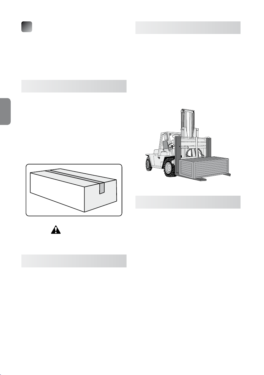
The unit is shipped in a cardboard box, covered with
a plastic sheet and enveloped by polyurethane foam
to protect it from damage in the event of impacts or
accidents.
2.1 Receipt
All units are carefully inspected before shipping.
Upon receipt, customers should verify that the
packaging and the material inside it has not
been damaged (unless otherwise instructed by
ENGLISH
TECNOMAGNETE S.p.A.) in order to ensure that the
unit has not been damaged during transport and that
the material supplied complies with order specications. Visible transport damages should be immediately reported to TECNOMAGNETE S.p.A. and the
forwarding agent.
ATTENTION
All damages and anomalies must be reported within
ten days from receiving the goods.
2.2 Handling
Weight of model ST100: 0,4 kg.
Weight of model ST200: 2,0 kg.
Always keep the original packaging so that it can
be used to transport the unit if needed.
2.3 Transportation
The unit should always be transported within the following environmental limits: temperature ranging
from –10°C to +55°C, with temperature increase up
to 70°C for a maximum of 24 hours.
If the unit requires the use of specic transportation
means (by sea or air), special provisions shall have to
be adopted in order to protect it from damages
caused by potential impacts. The box should also
contain hygroscopic salts to protect the unit from
atmospheric agents.
2.4 Storage
The unit should always be throughly cleaned and
adequately protected when stored for long periods
of time.
Disconnect the controller from the magnetic chuck
and from the power supply.
It is generally advisable to cover the unit with a waterproof bag and store it in dry and safe place.
The temperature of the storage area should range
between 0°C (32°F) and 55°C (131°F).
Relativy humidity should be between 30% and 90%,
non condensing.
The atmosphere should be clean, free from acids,
corrosive gases, salts, etc
When restarting the machine, always follow the instructions provided in Chapter 4.
36
Instruction and maintenance manual
3
DESCRIPTION
OF THE SYSTEM
3.1 Description of the controllers
ST is an innovative electronic controller for
networked chucks designed for milling and grin-
ding operations.
The sections that follow provide information on the
size and the basic characteristics of the available
models:
•
ST100F (milling)
•
ST100R (grinding)
•
ST200F (milling)
•
ST200R (grinding)
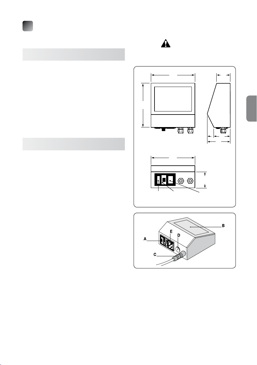
3.2 Model ST100X
The rated operating voltage is 230V.
The control push-button panel is integrated in to the
controller.
The control electronics are situated under the control
push-button panel and enclosed in a plastic housing.
To simplify installation and facilitate the reading of
the push-button panel, it is also possible to install
the controller on a workbench or mount it on the wall
by simply rotating the control panel.
The plastic material of the housing ensures a high
level of insulation and the utmost safety during use.
The rear part of the controller has a block with a male
pin (designed to be connected to the power cable),
an ON–OFF (0-1) switch and a fuse-holder with two
12.5A protection fuses (type 5x20 mm). Two or more
cable ties for the output of the discharge cables of
the chucks to be magnetized may be present next to
these components.
The maximum useful current that ows into the
ST100X controller is approximately 12.5A; the current supplied to the module is impulsive with a cycle
time around a few hundreds of milliseconds (app. 1
second per discharge).
ST100X controllers are suitable to control small
chucks with a single phase voltage of 230V and a
maximum absorption of rated current of 3kW.
For different rated voltages, use a transformer with a
suitable transformation ratio and a rating suitable to
handle the maximum power of the chuck or at any
Instruction and maintenance manual
rate a maximum power of 4kVA. For example, if the
available voltage is 400V, a transformer with a
400/230 transformation ratio is required.
ATTENTION!
Control units can be moved only
when controls are not powered.
135
135
Rear
135
Fuse-holder Main Power supply
switch input
40
50
75
40
MAIN PARTS
A ➜ Main switch
B ➜ Push-button panel
C ➜ Discharge cable output
D ➜ Start contact
E ➜ Power supply input
37
ENGLISH
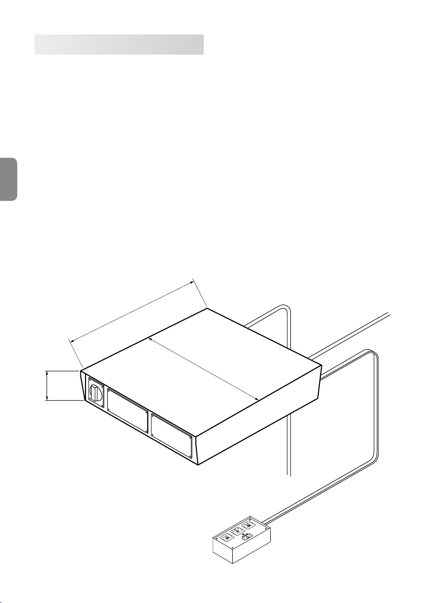
3.3 Model ST200X
The rated operating voltage of this controller varies
according to the type of magnetic chuck to which it
is connected.
The control push-button is external, but can also be
integrated into the controller.
The control electronics are enclosed in a metal housing. The metal material of the housing is grounded in
order to guarantee maximum safety during the enabling cycles.
It is important to verify that the grounding system is
always in good working order.
The controller does not have a socket for the connection to the power supply. The controller has an
ENGLISH
ON–OFF (0-1) switch, thus to adequately protect it
against short circuits, it is necessary to install a suitable protection system upstream from the controller.
It is generally advisable to use a magneto thermal
switch (curve C) with an In value compliant with the
rating specied on the magnetic chuck nameplate
that will be connected to the controller.
275
The maximum power of controller ST200X is approximately 25kW per discharge if the single phase
power supply is 400V, 15kW for power supplies of
230V and 30kW for power supplies of 480V. The absorbed current is impulsive with a cycle time around
a few hundreds of milliseconds (approximately 1
second per discharge).
ST200X controllers are suitable to power single
chucks or chucks that are part of large magnetic
banks
When using chucks with a different rated voltage,
install a transformer with a suitable transformation
ratio and a rated power that matches the maximum
power of the chuck.
It is also possible to order a compact version for
ST200-QE electric cabinets with supporting terminal
board, to power the controller and magnetic chuck,
with interface connector and push-button panel.
38
331
85
Instruction and maintenance manual
 Loading...