

TECNOMAGNETE MaxX 125, MaxX 300E, MaxX 250, MaxX Series, MaxX 1500 Use And Maintenance Manual
...
PERMANENT – ELECTRO MAGNETIC SYSTEMS
USSEE
U
LLiigghhtt DDuuttyy LLiiffttiinngg DDiivviissiioonn
hhaanndd ccoonnttrroolllleedd lliifftteerrss -- M
Lainate (MI) - Italy
Edition: May 2019
TRANSLATION OF THE ORIGINAL INSTRUCTIONS
according to LEGISLATION 2006/42/EC concerning machinery
A
A
N
N
D
D
M
M
M
M
A
A
AII
A
N
N
NTTEE
N
U
ALL
U
A
N
N
A
N
N
CEE
C
A
MaaxxXX
code 09MAXX001
version EN
revisione 01

2
CONTENTS
1 GENERAL NOTES ..................................................................................................................................................... 4
1.1
1.2
1.3
1.4
1.5
1.6
1.7
1.8
1.9
1.10 E
1.11 U
1.12 N
2 TRANSPORT AND HANDLING.................................................................................................................................. 7
2.1
2.2
2.3
2.4
P
RESENTATION
IMPORTANCE OF THE MANUAL .................................................................................................................. 4
ETENTION OF THE MANUAL
R
ONVENTIONS
C
D
EFINITION OF SYMBOLS
ERSONNEL ASSIGNED TO OPERATIONS
P
RAINED PERSONNEL
T
ERSONAL PROTECTIVE EQUIPMENT
P
ENERAL SAFETY WARNINGS
G
MERGENCY DRILL
NINTENDED OR IMPROPER USE
AMEPLATE DATA
R
ECEIPT
ANDLING
H
RANSPORT
T
NACTIVITY
I
...................................................................................................................................... 4
.................................................................................................................... 4
....................................................................................................................................... 4
......................................................................................................................... 5
....................................................................................................... 5
.............................................................................................................................. 5
(PPE) ................................................................................................. 6
.................................................................................................................... 6
.................................................................................................................................. 6
............................................................................................................... 6
.................................................................................................................................. 7
............................................................................................................................................... 7
............................................................................................................................................ 7
.......................................................................................................................................... 8
............................................................................................................................................ 8
3 DESCRITPION OF THE SYSTEM ................................................................................................................................ 8
3.1 A
3.2
3.2.1. A
3.2.2 C
3.2.3 T
3.2.4 M
3.3
4 MODELS AVAILABLE ............................................................................................................................................. 11
4.1
5 TECHNICAL CHARACTERISTICS .............................................................................................................................. 12
5.1
5.2
6 GENERAL DESCRIPTION OF THE SUPPLY ............................................................................................................... 14
6.1
7 INSTALLATION ...................................................................................................................................................... 14
7.1
8.1 RISKS RELATED TO MAXX LIFTERS ............................................................................................................ 16
8.2 P
8.3 E
8.4 A
DVANTAGES
ASIC PRINCIPLES OF MAGNETIC CLAMPING WITH MAX
B
IR GAP AND ROUGHNESS
ONTACT SURFACE
YPE OF MATERIAL
ATERIAL THICKNESS
AGNETIC FORCE
M
MAXX ........................................................................................... E
MAXX TECHNICAL CHARACTERISTICS .............................................................................................. 12
MAXX
MAXX
G
ENERIC INSTALLATION
ERSONAL PROTECTIVE EQUIPMENT
XPOSURE TO MAGNETIC FIELD
CTION LEVELS
........................................................................................................................................ 8
X ............................................................................... 9
..................................................................................................................... 10
............................................................................................................................... 10
............................................................................................................................... 10
........................................................................................................................... 10
................................................................................................................................ 11
RRORE. IL SEGNALIBRO NON È DEFINITO
DIMENSIONS AND WEIGHTS
DESCRIPTION OF THE SUPPLY
......................................................................................................................... 14
(LA)
OF THE STATIC MAGNETIC FIELD
.......................................................................................................... 13
........................................................................................................ 14
......................................................................................................... 16
............................................................................................................... 16
.................................................................................. 17
.
Use and Maintenance Manual
MaxX
codice 09MAXX001
versione EN
revisione 01

3
THE FOLLOWING IS THE BASIC OPERATING PROCEDURE FOR USING THE MAXX .......................................................... 18
9.1
9.2
10 CHECKS AND MAINTENANCE ................................................................................................................................ 19
10.1 C
10.2 C
10.3 D
10.4 F
10.5 P
10.6 M
10.7 D
10.8 F
10.9 P
10.10 S
11 PROBLEMS AND RELATED SOLUTION ................................................................................................................... 22
11.1 P
12.1 D
12.2 D
O
PERATING PROCEDURE - MAGNETIZING AND HANDLING
O
PERATING PROCEDURE - DEMAGNETISATION
ONTROLS – STANDARDS
HECKS - METHOD
AILY CHECK
REQUENT CHECK
ERIODICAL CHECK
AINTENACE - WARNINGS
AILY MAINTENACE
REQUENT MAINTENANCE
ERIODICAL MAINTENANCE
UMMARY TABLE MAINTENANCE/CHECKS
ROBLEMS
ECOMMISSIONING
ISPOSAL
....................................................................................................................................... 20
......................................................................................................................................... 22
........................................................................................................................................... 22
...................................................................................................................... 19
............................................................................................................................... 19
................................................................................................................................ 20
............................................................................................................................... 20
.................................................................................................................... 20
............................................................................................................................. 20
..................................................................................................................... 20
.................................................................................................................... 20
............................................................................................................................. 22
............................................................................ 18
........................................................................................... 19
................................................................................................ 21
13 SPARE PARTS ........................................................................................................................................................ 22
13.1 S
14 WARRANTY AND SERVICE .................................................................................................................................... 23
14.1 WARRANTY CONDITIONS ................................................................................................................ 23
14.2 WARRANTY EXPIRATION ................................................................................................................. 23
15 TECNOMAGNETE SERVICE NETWORK ................................................................................................................... 24
16 ANNEXES .............................................................................................................................................................. 24
16.1 D
PARE PARTS
ECLARATION OF CONFORMITY
....................................................................................................................................... 22
.............................................................................................................. 24
Use and Maintenance Manual
MaxX
codice 09MAXX001
versione EN
revisione 01

1 GENERAL NOTES
Congratulations on choosing a TECNOMAGNETE product.
This publication will help you find out more about your new
product and we recommend that you carefully read these
pages and always follow the instructions. The descriptions
and illustrations contained in this publication are not
difficult, given the basic features of the product described.
TECNOMAGNETE reserves the right to make changes at any
time to components and accessories in order to improve
the product or due to manufacturing or commercial
requirements. Updates of this manual will be provided as
required as Annexes or on the website
ww.tecnomagnete.com
of this manual and its reproduction, even partial, is
prohibited, as is disclosure to third parties, without its
written permission. In the event of changes and/or updates
to the product, which will be agreed exclusively with
TECNOMAGNETE, additional content concerning the use
and any residual risks arising from the changes shall be
provided to supplement the manual.
1.1
Presentation
TECNOMAGNETE was founded in 1974 and has attained a
position of leadership position in world markets as a
manufacturer of powerful, flexible permanent-electro
magnetic systems that operate in total safety, due to its
innovative technology and numerous patents filed over the
years. Permanent-electro magnetic systems produced by
TECNOMAGNETE are able to generate sufficient magnetic
force both for clamping and lifting workpieces, only
consuming electricity when turned on and off.
The main fields of operation include:
MACHINE TOOLS CLAMPING SECTOR
Grinding series
Milling series
Turning series
Rail machining series
MOULDING SECTOR
Systems for clamping press molds
LIGHT LIFTING SECTOR
Manually-controlled lifters
Battery-powered lifters
HEAVY LIFTING SECTOR
Magnetic lifters
Fixed beam magnetic module beam
. TECNOMAGNETE retains ownership
4
Telescopic beam magnetic module beam
Importance of the manual
1.2
A copy of this manual must be distributed and kept
available to operators assigned to the installation,
operation and maintenance of MaxX, enabling them to
operate in accableance with the instructions given in this
document. A careful reading of the manual will enable
MaxX to be used in the correct way and safeguard the
security and safety and operators and others. This manual
is an integral part of the MaxX, and all reproduction and
dissemination rights of the manual and its attachments are
reserved. Pass this manual on to any other user or
subsequent owner.
1.3
Retention of the manual
Making changes to and removing parts of this manual are
prohibited. When using the manual, take care not to
damage it. Keep the CD-R or USB key away from impact,
heat and magnetic sources and make it easily accessible to
operators for further reference.
Conventions
1.4
For ease of consultation, the manual is divided into the
following hierarchical order so that each phase is described
in detail:
1. Chapter 1 of the manual
1.1. section 1 of Chapter 1 of the manual
1.1.1. sub-section 1 of section 1 of Chapter 1 of the
manual
Some sections and/or chapters are presented with
numbered sequences in order to illustrate the operation
step by step.
Symbols are given in sections requiring greater attention.
Units of measurement, including the decimal point, are
displayed with the international system (SI).
Use and Maintenance Manual
MaxX
codice 09MAXX001
versione EN
revisione 01
5
Definition of symbols
1.5
All parts concerning safety are highlighted in bold.
All warning notes that alert the personnel concerned that
the described operation involves exposure to residual risk,
with possible damage to health or injury, if not carried out
in compliance with the instructions, are shown in bold and
identified with the following symbol :
All warning notes that indicate that the described
operation must be performed by trained and qualified
personnel are shown in bold and indicated with the
following symbol:
In turn, the trained / specialized personnel, depending on
the specific tasks, can be indicated by the following
symbols: (see details in paragraph 1.7)
Personnel assigned to
1.6
operations
As indicated in this manual, certain procedures must be
carried out only by qualified or trained personnel.
The level of qualification is described using standard terms:
1. qualified personnel have technical knowledge and/or
sufficient experience to enable them to avoid thepotential
dangers from electricity and/or mechanical movements
(operation and maintenance personnel) trained personnel
are appropriately advised and/or supervised by qualified
persons to enable them to avoid the potential dangers from
electricity and/or mechanical movements (operation and
maintenance personnel)
2. the User is obliged to obtain confirmation of
the following from all designated persons, before they are
allowed to work to work with MaxX the personnel have
received the instruction
2.1. the personnel have received the instruction manual, and
have read and understood it
2.2. the personnel shall work in the manner described..
Trained personnel
1.7
The qualifications are given below of the personnel
allowed to use the MaxX:
OPERATOR: a person or persons who,
following appropriate and indispensable training, is/are
assignedand authorized by the owner of the MaxX to run
operations. The occupier of this post must be completely
aware of and understand the contents of this manual
HANDLER: this post requires specific skill
(possibly acquired by attending mandatory courses, if
required by law, in hoists the methods and features of
harnesses handling and safe handling procedures. This
position also requires complete awareness and
understanding of the contents of this manual, in particular
paragraph 2.2
MECHANICAL MAINTENANCE OPERATOR:
this post requires specific skills in the installation, adjustment,
maintenance, cleaning and/or repair of systems. The occupier of
this post must be completely aware of and understand the
contents of this manual.
requires specific skills in carrying out installation, adjustments,
maintenance cleaning and/or repair. For his preparation and
experience he has skills and knowledge in the lifting sector as
well as a sufficient familiarity with the main regulations in order
to be able to determine any deviations from the expected
conditions.
The occupier of this post must be completely aware of and
understand the contents of this manual.
SPECIALIZED TECHNICIAN:
this post
Use and Maintenance Manual
MaxX
codice 09MAXX001
versione EN
revisione 01
6
1.8
Personal protective
equipment (PPE)
The staff referred to in the previous paragraph must wear an
adequate safety distance from the parts clamped on the
magnetic equipment, with special attention when in vertical or
suspended (this distance must be suggested by the plant
operator in accordance with the regulations). The staff must
also wear appropriate safety clothing. Protective footwear is
mandatory, while the need for
headsets, helmets and goggles must be assessed by the
User. Loose fitting clothes or articles that could be trapped by
moving parts are prohibited.
(see chapter 8)
General safety warnings
1.9
The rules and recommendations below are in compliance
with the current safety regulations, on which they are
based. TECNOMAGNETE S.p.A. declines all responsibility for any
damage caused to persons or things deriving from failure to
observe the safety regulations in force and the instructions given
below.
Machine safety systems must be selected and installed on
the basis of the following requirements:
be under the technical responsibility of qualified
personnel
be integrated with technical compliance and with
appropriate control systems
installations must be made in such a way that they can
not be neutralized or tampered with
All designated operators must respect and implement the
following and scrupulously adhere to the regulations on
accident prevention in force in the country of installation and
on the use of the MaxX. All ordinary and extraordinary
maintenance must be performed with stationary system and
with structure not hooked to the crane etc.
To avoid the danger of accidental connections during
maintenance operations, attach a warning sign on the control
panel with the words:
MAINTENANCE IS UNDERWAY
All operations of transport, installation, use, ordinary and
extraordinary maintenance on the MaxX must only be carried
out by the personnel identified in section 6 of chapter 1.
The permanent-electro magnetic system can only be used for
the applications indicated in the manual and only in
combination with devices and components recommended and
authorized by TECNOMAGNETE S.p.A.
1.10
In an emergency, it is recommended to follow the procedures
given in the operation and maintenance manual of the machine
on which the MaxX is installed. In the event of fire, use the
devices provided to extinguish the fire, taking care never to use
water on electrical parts (considering however that MaxX is not
made up of electrical parts).
1.11 Unintended or improper use
Emergency drill
MaxX is not designed or constructed for operation in explosive
atmospheres.
Unintended use may:
cause injury to personnel
damage the system or other equipment
diminish reliability and performance.
MaxX cannot be used for purposes other than those
recommended and in compliance with the intended use,
avoiding the following in particular:
unsuitable parameters of use
defective or lack of maintenance
use of inappropriate materials
failure to follow instructions
uncertain or insecure clamping of MaxX system or parts
thereof
In the events of doubts over the appropriate usage,
contact TECNOMAGNETE S.p.A. to determine whether it is use
for which the system was intended or otherwise.
Use and Maintenance Manual
MaxX
codice 09MAXX001
versione EN
revisione 01
7
1.12
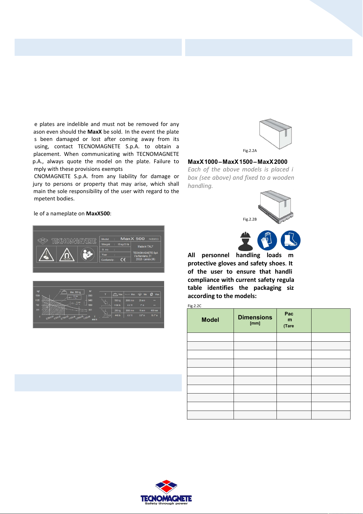
Two plates are applied on the MaxX:
1) Logo and data referring to the identification of the
2) Load / force curves, data referring to the performances and
3) The plates are indelible and must not be removed for any
Example of a nameplate on MaxX500:
Fig.1.12A
Nameplate data
manufacturer, serial number, production date, weight of the
MaxX, symbology in compliance with the laws in force
(example Fig.1.12A).
dimensions and types of load to be magnetically anchored
(example Fig.1.12B).
reason even should the MaxX be sold. In the event the plate
has been damaged or lost after coming away from its
housing, contact TECNOMAGNETE S.p.A. to obtain a
replacement. When communicating with TECNOMAGNETE
S.p.A., always quote the model on the plate. Failure to
comply with these provisions exempts
TECNOMAGNETE S.p.A. from any liability for damage or
injury to persons or property that may arise, which shall
remain the sole responsibility of the user with regard to the
competent bodies.
2.2
MaxX 125 – MaxX 250 – MaxX 300E – MaxX 500 – MaxX 600E
MaxX TG 150 – MaxX TG 300
Handling
Each of the above models is placed inside cardboard boxes,
protected by a sheet and wrapped in a layer of
polyurethane foam that guarantees the absolute
mechanical integrity in case of shocks or incidents of the
packaging.
Fig.2.2A
MaxX 1000 – MaxX 1500 – MaxX 2000
Each of the above models is placed inside the cardboard
box (see above) and fixed to a wooden pallet to allow easy
handling.
Fig.2.2B
Fig.1.12B
2 TRANSPORT AND
HANDLING
2.1
Receipt
MaxX are thoroughly checked before shipment. On receipt, the
integrity of the package and the material contained therein must
be checked (unless other instructions are issued by
TECNOMAGNETE S.p.A.), in order to confirm that no damage
occurred during transport and that the consignment complies
with the order specifications. Otherwise, report any irregularities
to TECNOMAGNETE S.p.A. and the Carrier responsible for any
damage during transport.
Notification of damage or defects must be given within ten days
from receipt of the supply. After that period, TECNOMAGNETE
S.p.A. will consider the provision free of defects.
All personnel handling loads must operate with
protective gloves and safety shoes. It is the responsibility
of the user to ensure that handling is conducted in
compliance with current safety regulations. The following
table identifies the packaging size and its weight
according to the models:
Fig.2.2C
Model
MaxX 125
MaxX 250
MaxX 300E
MaxX 500
MaxX 600E
MaxX 1000
MaxX 1500
MaxX 2000
MaxX TG150
MaxX TG300
Dimensions
[mm]
130x130x200 0.3 4
195x145x200 0.5 7
195x145x200 0.5 7
255x190x245 1 16
255x190x245 1 16
350x230x250 3.5 36
400x300x300 5 66
460x300x300 6 82
195x145x200 0.5 7
255x190x245 1 16
Packing
mass
(Tare) [kg]
Complete
packing
(Gross) [kg]
Use and Maintenance Manual
MaxX
codice 09MAXX001
versione EN
revisione 01
8
Inactivity
2.4
When hoisting or handling MaxX, clear the operations
area of obstructions and keep it clear, also consider
providing a sufficient safety zone to prevent harm to
persons, animals or objects that might be in maneuvering
range. MaxX are designed to be hoisted and handled
with suitable hoisting devices, the type and scope of
which must be selected in accableance with the weight.
(see table Fig.2.2C). It must be handled with extreme
care, avoiding impacts that could damage delicate parts,
compromising normal operation When moved with
forklift trucks, comply with the permitted speed and
inclination. Never leave load suspended on hoists. (also
refer to paragraph 1.8).
The permanent-electro magnetic system must be
disconnected from power sources and its moving parts
appropriately locked during transport, handling and
storage.
The instructions on the package must be read and
digested before opening.
Keep the original packaging for later handling.
2.3
Transport
Some parts may have to be dismantled for transport, to be
reassembled and reconnected during installation by
TECNOMAGNETE S.p.A. technicians, or by the User on
TECNOMAGNETE S.p.A.’s recommendations. The system must be
transported in observance of the following environmental limits:
a temperature range of -5 °C to +55 °C, rising to a maximum of
+70 °C for a period no longer than 24 hours. Should it be
necessary to transport the MaxX by sea or by air, suitable
packaging and protection systems must be provided to avoid
any damage caused by impact. To protect against weathering,
use anti-rust lubricants and bags of hygroscopic salts inside the
packages. All moving parts must be properly anchored and
removed from their housing, where possible.
In the event of long-term storage or inactivity, the MaxX must be
thoroughly cleaned of any residues and its uncovered metallic
parts must be protected with oil or grease in order to avoid
oxidation. It is recommended to cover the MaxX with a tarpaulin
and keep them in a dry, sheltered place The room temperature
should be between -5 ° C (23 ° F) and + 55 ° C (131 ° F). The
relative non-ondensing humidity should be between 30% and
90%, The atmosphere should be clean, free of acids, corrosive
gases, salts, etc. If restoring to operation, follow the instructions
contained in this manual.
3 DESCRITPION OF THE
SYSTEM
Advantages
3.1
MaxX consists of a very small number of details. Rotor and
stator, in steel with high magnetic permeability, are obtained by
machining from solid, using CNC machines; this grants uniformity
and robleness of the product and the quality control necessary
for a magnetic hoist built in large series.
The material used (steel, aluminum, plastic) is easily disposable
and recyclable when the tool is dismantled.
The magnetic material used, with a high specific energy, made it
possible to reduce to the maximum weight and volume.
To allow a high uniformity of performance, given the large series,
the MaxX lifter is magnetized in a single stroke after assembly,
using the largest magnetizer built in Europe.
MaxX is able to handle the load, which is always anchored and
lifted from above, without any deformation or damage with an
optimal use of the available work areas.
Some of the most recognized areas with the use of MaxX are the
following:
- servicing of machine tools
- wholesalers of ferrous material
- cutting plants
- carpentry
- shipyards
- foundries
- steel industries
- mold handling
Use and Maintenance Manual
MaxX
codice 09MAXX001
versione EN
revisione 01
 Loading...