

Page 1
INSTRUCTION MANUAL
OUR SYSTEMS COMPLY WITH DIRECTIVES 73/23 EEC - 89/336 EEC
ISO 9001
Cert. N° 0412/2
Cod. 71503560/0 - 12/2003
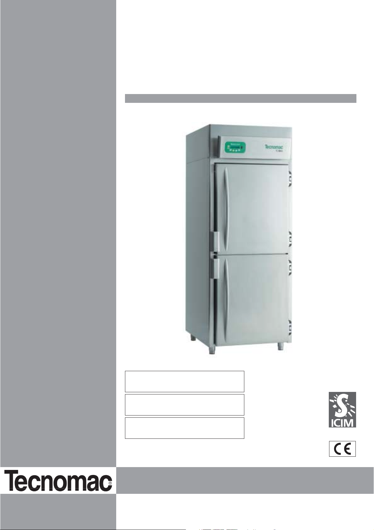
PRESERVATION CABINETS
TECNOCONTROL
TC 60-N
-10 / -22 °C
TC 60-P
+8 / -2 °C
TC 60-C
+15 / +2 °C
HR 40% / 90%
Page 2

CONTENTS
1. GENERAL DOCUMENTATION
1.1 General information page 4
1.2 Installation page 4
1.3 Transport and handling page 4
1.4 Unpacking - disposal of packing page 4
1.5 General safety regulations page 5
2. INSTALLATION
2.1 Dataplate information page 5
2.2 Positioning page 5
2.3 Ambient temperature and air circulation page 6
2.4 Electrical connections page 6
2.5 Connection of refrigerator - remote units page 6
2.6 Condensate drainage connection page 6
2.7 Notes for the installer page 6
2.8 Safety and control systems page 7
2.9 Appliance disposal page 7
3. TECHNICAL CHARACTERISTICS page 8
4. PROGRAMMING INSTRUCTIONS
4.1 Starting up the appliance page 9
4.2 Language setting page 9
4.3 Date and time setting page 10
4.4 Set-point setting and display page 10
4.5 Cell loading function page 10
4.6 Continuous cooling function page 10
4.7 Door microswitch function page 10
2
GB
Page 3

5. DEFROST MANAGEMENT
5.1 Manual defrost page 11
5.2 Periodic defrosting page 11
5.3 Timed defrosting page 11
6. MANAGING AND SILENCING DETECTED ALARMS
6.1 Storing alarms page 12
6.2 Silencing alarms page 12
6.3 Alarms list page 12
6.4 Serious alarms list page 13
6.5 List of other operating faults not indicated page 14
7. MAINTENANCE AND CLEANING
7.1 Basic safety regulations page 15
7.2 Cleaning the condenser page 15
7.3 Cell cleaning page 16
7.4 Defrost water drainage page 16
3
GB
Page 4
4
GB
1. GENERAL DOCUMENTATION
1.1. General information
• This manual is an integral part of the product and provides all the information
necessary for ensuring correct appliance installation, operation and maintenance.
• Read the manual carefully, and always
consult it for appliance operation. Keep
the manual in a well-known place accessible to all authorised operators (installers, users and maintenance personnel)
The appliance complies with Directives
73/23/EEC (low-voltage), 89/336/EEC
(electromagnetic compatibility) and
machines 98/37/EC (for some models
only).
• The appliance is designed for professional use and therefore must only be operated by qualified personnel.
• The appliance must only be used for its
designed purpose, i.e. for preserving
food products.
The appliance must not be used for products requiring constant temperature
control and recording, such as
- heat-sensitive chemicals,
- medicines
- blood derivatives.
• The manufacturer declines all responsibility for any damage caused by incorrect
or unreasonable use, such as:
• improper use by untrained persons
• technical modifications or operations
that are not specific to the models
• use of non-original or non-specific
spare parts
• failure to follow the instructions given
in this manual
1.2 Installation
The appliance must only be installed by
specialised personnel authorised by
Tecnomac, according to the instructions
given in this manual.
If the appliance is fitted with a remote condenser unit, the installer is responsible for
checking all connections in compliance
with the instructions given by Castelmac
for plant and appliance installation.
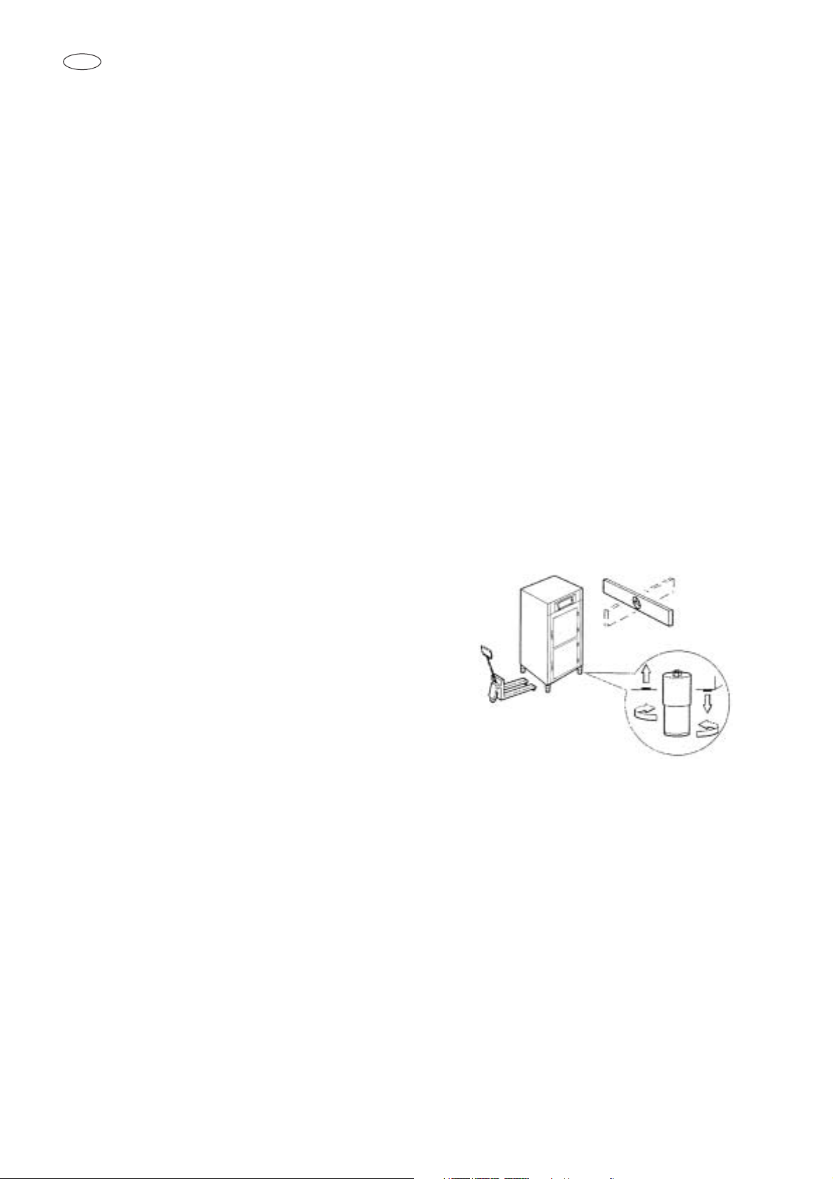
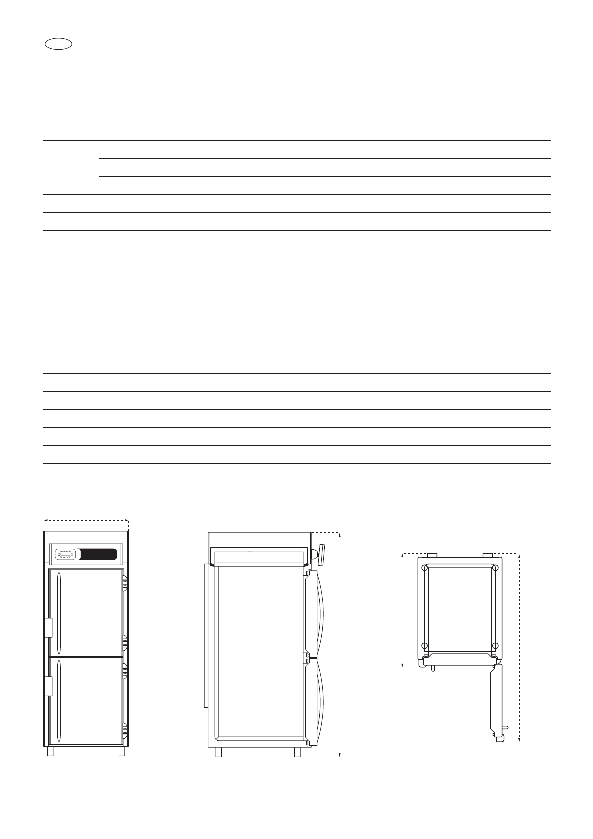
1.3 Transport and handling
• Loading or unloading the appliance
and/or subsystems from/onto the means
of transport can be done with a lift truck
or fork lift equipped with forks at least
half the length of the cabinet; or a crane
if the appliance is fitted with eyebolts.
Choose lifting equipment suitable for the
weight and overall dimensions of the
packed appliance/components.
• When handling the appliance/subsystems, take all necessary precautions to
prevent damage, complying with the
indications given on the packing (fig. 1)
1.4 Unpacking
• Remove all packing in cardboard, wood
or boxes from the wood base on which
they are placed. Lift the
appliance/subassemblies with suitable
means (e.g. lift truck), remove the wood
base, then position the appliance/subassemblies in the required place.
• After removing the packing, check the
integrity of the appliance.
• Remove the protective PVC film on the
panels, from all internal and external
Page 5
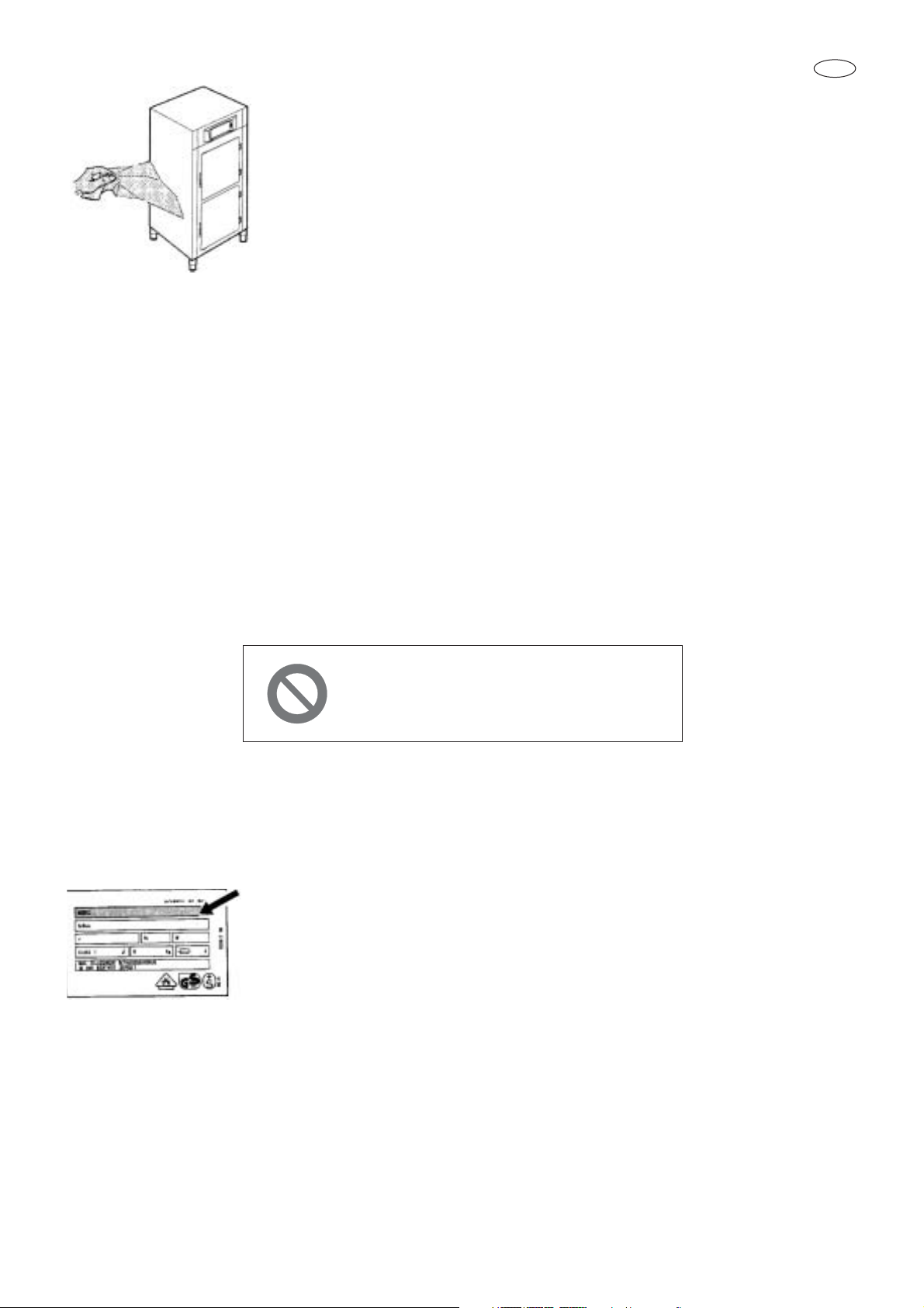
2.1 Data plate information
• Check that the data specified on the
plate correspond to the characteristics of
the power supply (V,
kW, Hz, no. phases
and power available)
• The data plate
with appliance specifi-
cations is located at the
rear exterior of the machine and/or on the
electrical control boxes. Any preparation
of individual appliances for the positioning
of condensing units must comply with the
current fire-prevention regulations in the
country of installation (see the local fire
department for the necessary details).
Bear in mind that any intervention of safety valves or fuse plugs in the refrigerating
circuit will lead to the immediate discharge of refrigerant into the environment.
2.2 Positioning
• The appliance must be installed and
commissioned in full compliance with
safety regulations, procedures and current laws
• The installer must ensure compliance
with any fire-prevention provisions (see
the local fire department for the necessary details).
• Position the appliance in the allocated
site
• Adjust the feet until the appliance is perfectly level. For levelling heavy appliances, use appropriate lifting means
WWWWAAAARRRRNNNNIIIINNNNGGGG !!!!!!!!!!!!
THESE OPERATIONS MUST BE ONLY
PERFORMED BY A
LICENSED INSTALLER
2. INSTALLATION
5
surfaces (fig. 2)
•
Always wear protective gloves when
handling packing material and the
wood base.
• NB: Dispose of packing materials in compliance with current regulations in the
country where the appliance is installed.
Do not disperse materials in the environment.
1.5 General safety regulations
The user is fully responsible in case of any
operations carried out on the appliance
and not in compliance with the instructions
given in this manual. The main safety regulations are as follows:
-
do not touch the appliance with moist
or wet hands or feet - do not operate
on the appliance when barefoot;
- do not insert screwdrivers, kitchen
utensils or any other object between
the guards and moving parts
- before performing cleaning or routine
maintenance operations, disconnect
the machine from the power supply by
operating the main switch, also
disconnecting the main knife switch
(if present)
- do not pull the power cable to disconnect the appliance from the power
supply
GB
Page 6
6
GB
(fig. 1)
• If the appliances are not perfectly level,
their correct operation and condensate
run-off may be compromised.
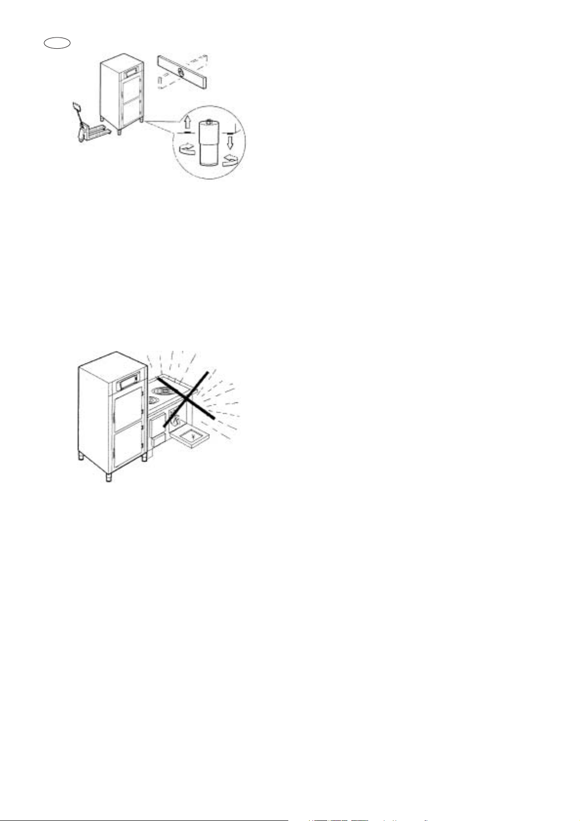
AVOID
• direct exposure to sunlight
• closed sites with high temperatures and
poor air circulation
• Do not install the appliance near any heat
sources (fig. 4).
2.3 Ambient temperature and
air circulation
For air-cooled refrigerating units, the
maximum ambient temperature for operation is 32°C. Correct operation cannot
be guaranteed at higher temperatures.
The appliance can operate safely up to
38°C.
Remote condensing units must be installed in special rooms or outdoors, in a
place protected against direct sunlight; if
necessary the installer must evaluate the
use of a covering or roof structure (the
costs are borne by the purchaser).
In any case, sufficient air interchange
must be guaranteed.
2.4 Electrical connections
A differential thermal-magnetic circuit
breaker complete with disconnecting
switch must be installed ahead of every
appliance, in accordance with current
regulations in the country of installation.
• Electrical connection cables must comply with the characteristics given in the
technical data (see appliance wiring diagrams, the installer’s responsibility)
The earth wire must be correctly connected to an efficient earthing system.
THE MANUFACTURER DECLINES ALL
LIABILITY AND WARRANTY OBLIGATIONS IN THE EVENT OF INJURY TO
PERSONS OR DAMAGE TO EQUIPMENT AND THINGS, DUE TO INCORRECT INSTALLATION AND/OR FAILURE TO COMPLY WITH CURRENT
LAWS.
2.5 Connection of refrigerator-remote
units
Appliance feed lines are sized for installation distances of up to 10 metres. For
greater distances, contact Castelmac.
2.6 Condensate drainage connection
For all models, fit a condensate/wash
water drainage hose with a minimum diameter of 1” (“geberit” type or similar).
2.7 Information for the installer
Before starting up the machine, check
that it has been correctly installed and
commissioned (test report)
1. Make sure there are no gas leaks from
welds or joints made during the installation phase.
2. Check that the pipes connecting the condenser to the remote condensing unit
have been well insulated.
Page 7

7
3. Check all wiring connections.
4. Check electrical input.
5. Check the standard pressure of the refrigerating system.
6. Check the water connection with adjustment of the pressure switch valve during
operation and the correct flow of condensing water (in water-cooled units).
7. Check that the preservation unit reaches
the set temperature and do a manual
defrost.
If the appliance or the remote condensing unit have not been transported in an
upright position (e.g. horizontally) or
have been overturned during installation,
wait at least 4 hours before starting up
the equipment.
• Inform the customer of the exact use of
the appliance, with specific reference to
the use and requirements of the customer.
Installation and commissioning
must be carried out by authorised
Castelmac personnel.
2.8 Safety and control systems
• Door microswitch:
shuts off fans in the cell when the door is
opened.
• Main fuses:
protect the power circuit against short circuiting and overloads
• Safety thermostat:
intervenes when the appliance overheats
due to extended operation of evaporator
defrosting elements
• Safety pressure switch:
intervenes in the event of overpressure in
the refrigerant circuit
• Mechanism to open door from inside
should the door accidentally close
• Chamber temperature control:
controlled by the electronic board by
means of the sensor located inside the cell
• End of defrost temperature control: controlled by the electronic board by means of
the sensors on the evaporator.
• Internal humidity control (for TC 60-C only)
This is controlled by the electronic board by
means of the sensor located inside the cell.
2.9 Appliance disposal
The appliance must be demolished and
disposed of in compliance with current
regulations in the country of installation,
above all with regard to the refrigerant
gas and compressor lubricant oil.
GB
Page 8
8
GB
(*) Evaporation temperature -10 °C ∆ 120x165x360 mm.
(**) Evaporation temperature -28 °C
890 mm
2350 mm
1990 mm
1200 mm
3. THECNICAL CHARACTERISTICS
TC60-N TC60-P TC60-C
Width 890 890 890
Depth 1200 1200 1200
Height 2350 2350 2350
Thickness of insulation 70 mm
Tray size 600 x 800 mm (not supplied)
Max. no trays (distance between trays 50mm): 30 (600 x 800 mm); 60 (600 x 400 mm)
Distance setting between trays 10mm
20 pairs of guides for 600 x 800 mm trays provided.
TECHNICAL SPECIFICATIONS
Temperature °C -10 / -22 +8 / -2 +15 / +2
Power supply 220-230V/50HZ 220-230V/50HZ 220-230V/50HZ
Refrigerant R404a R404a R404a R404a
Current absorbed 7.5 A 4.2 A 5 A
Input power 886 W 700 W 860 W
Defrosting Hot gas
Dehumidification control
Can be programmed from 40% to 90% (available with TC60-C version only)
HACCP 24/7 internal temperature control with alarm registration
Built-in condensation unit (remote-controlled on request)
Outside
dimensions
mm.
Page 9

9
4.1 Starting up the appliance
Power up the preservation unit using the
main switch.
Switch on the controller, holding down the
ON/OFF pushbutton. The controller will dis-
play the welcome message and show the
installed software and go to the following
box:
Message with compressor switched off and
display of temperature inside cell.
The cabinet prepares for operation at the
preset temperature.
Message with compressor switched on and
display of temperature inside cell.
The display shows the temperature detected
by the sensor inside the cell.
To switch off the controller, hold down the
ON/OFF pushbutton for 5 seconds; after
this the controller will go on a low voltage
stand-by operation mode and will display the
following boxes:
The message displayed on the LCD screen
in OFF is WAITING with cursor flashing.
IMPORTANT: to turn off the power to the
controller use the main switch.
4.2 Language setting
Press the MENU button and with the or
buttons go to
MENU 7 LANGUAGE;
press the ENTER button to display the first
language. When the or button is
pressed again the available languages are
selected.
Menu 7
LANGUAGE
WAITING _
OFF
COOLING >>OK
CELL -14,5°C
PAUSE >>OK
CELL -14,5°C
4. PROGRAMMING INSTRUCTION
ON/OFF
Continuous
cooling
function
Infrared
data
receiver
Selects the
menus
Decreases
the value
Confirms entering
the selected
menu or
the selected value
Increases
the value
GB
Page 10
10
GB
When the desired language is displayed,
press the
ENTER button; the controller
requests a second confirmation, displaying
EXIT or CONFIRM.
Press the button to confirm or the
ENTER
button to exit and return to the first box.
4.3 Date and time setting
Press the MENU button and with the or
buttons go to
MENU 8 SET CLOCK;
press
ENTER and the date and time will be
displayed with the first figure of the day flashing. Change the figure with the or buttons
and confirm the value with the
ENTER but-
ton; the new value is stored and the month
figure will flash.
Repeat the procedure until arriving at the
seconds value, then press the
ENTER but-
ton. When the values have been stored, the
date and time will flash.
4.4 Set-point display and setting
Press the MENU button and with the or
buttons go to
MENU 2 CHANGE SET
POINT
; press the ENTER button; the set
temperature and the temperature to be modified will be displayed. Modify the
NEW SET
temperature using the button to increase
the value by N degrees and the button to
decrease the value by N degrees. To store
the new set temperature press the
ENTER
button.
The new value will flash to confirm it has
been stored.
4.5 HUMIDITY ADJUSTMENT
(on TC60C only)
Press the MENU and use the
or
but-
tons to open the
MENU 3 - CHANGE HUMID-
ITY window; press ENTER; the current
humidity level and the new one to be set will
be shown. Use the
or
buttons to
change the humidity
NEW RH% and press
ENTER to confirm. The value will blink to
confirm it has been accepted.
Humidity values can be varied within an
accepted range of 40% to 90%.
4.6 CONTINUOUS COOLING FUNCTION
Hold the button for a few seconds to turn
on the continuous cooling function.
CONTINUOUS COOLING will appear on the
display; press
or
to set the continuous running time limit of the compressor
(MAX 6 HOURS). With this function,
HIGH/LOW temperature alarms are inhibited.
At the end of Continuous Cooling the preservation unit returns to normal working conditions.
4.7 Door microswitch function
The controller signals door opening, showing
the following box on the display:
The evaporator fans will stop each time one
of the doors is opened and will restart when
the door is closed. If the door stays open for
more than 5 minutes, the warning buzzer is
activated and the evaporator fans will restart
as though the door were closed.
DOOR OPEN >>OK
Cell -21°C
NEW SET: -15°C
PRESENT: -15°C
Menu 2
CHANGE SETPOINT
Date: 12/04/03
Time: 11:54:23
Page 11

11
5.1 Manual defrost
A manual defrost can be activated: press the
MENU button, with the or buttons go
to MENU 4 DEFROST and press the ENTER
button.
The controller requests a further confirmation, displaying
EXIT or CONFIRM. Press the
button to confirm or the
ENTER button to
exit and return to the first box.
Message with defrost active:
At the end of defrosting the compressor will
restart and the display will show the word
REGENERATION until the set-point temperature is reached.
Defrosting is completed when the set-point is
reached (detected by the two sensors located on the evaporator) or when the maximum
defrost time is reached.
In the case of maximum time being reached
the controller signals the anomaly with the
following intermittent alarm message and the
buzzer:
The controller memorises the type of alarm,
date and time.
To cancel the alarm message press the
ENTER button.
In any case, the alarm is stored in the controller’s alarms memory.
5.2 Periodic defrosting
For all models, defrosting can be repeated
automatically at regular intervals, beginning
immediately after the appliance is switched
on.
The time between automatic defrosts is factory-set at 6 hours.
Also in this case, defrosting is completed on
reaching the set-point (detected by the two
sensors on the evaporator) or when the maximum defrost time is reached.
The anomaly is signalled as in the case of
manual defrosting.
5.3 Timed defrosting
It is possible to set the starting time for 4 daily
automatic defrosts that will always be repeated in a 24-hour time period. In this mode,
automatic periodic defrosts are disabled.
Defrosting is completed as described above.
F18 DEFROST TIME
S 19/02/02 06:09
DEFROST TIME
—> Call SERVICE
REGENERATION >>OK
CELL -10,5°C
DEFROST >>OK
CELL -18°C
Menu 4
DEFROST
5. DEFROST MANAGEMENT
GBGB
Page 12

12
GB
6.1 Storing alarms
The controller is equipped with visual and
acoustic signalling of alarms caused by
appliance operation anomalies.
A maximum of 16 alarm events are stored;
further alarms will overwrite those already
recorded. The alarms are signalled by a
buzzer and the display will show the type of
alarm.
There is signalling delay only for HIGH/LOW
cell temperature alarms, which are signalled
60 minutes after being detected.
The controller will show the HIGH or LOW
temperature pre-alarm on the display, storing
it in the alarms list when the time has
elapsed.
Cell high temperature pre-alarm message
Cell low temperature pre-alarm message
When the pre-alarm time has elapsed the
controller will show the following message:
To cancel the alarm enter the
MENU 1
ALARMS LIST.
6.2 Silencing alarms
To silence the buzzer during an alarm press
the
ENTER button
6.3 Alarms list
It is possible to display the alarms that the
controller stored during its operation.
To enter the display press
MENU, with the
or buttons go to
MENU 1 ALARMS
LIST and press ENTER.
Using the or buttons scroll the alarms
stored by the controller.
The controller stores the type of alarm, the
start date of the alarm and its duration in
minutes.
If the and buttons are pressed at the
same time the date of the last alarm reset is
displayed. The maximum and minimum temperature alarm also displays the maximum
and minimum temperatures reached.
In the blackout alarm the date/time of power
failure start and finish is recorded. If no
alarms have been stored the controller displays
NO EVENTS IN MEMORY.
Example of high temperature alarm:
AL 27: HIGH TEMP.
Duration 015’
AL 27: HIGH TEMP.
S.=18/03/02 12:29
AL 27: HIGH TEMP.
Max Temp.= +25°C
ALARM DETECTED
CELL -24,0 °C
PAUSE >>Lt
CELL -24°C
COOLING >>Ht
Cell -18°C
6. MANAGING AND SILENCING
DETECTED ALARMS
Page 13

13
FAULT MESSAGES (they compromise appliance operation - CALL THE TECHNICAL ASSISTANCE SERVICE)
MESSAGE DISPLAY CAUSE CANCELLATION
ERR. SENSOR S1 Intermittent Temperature sensor fault Automatic on elimination of fault
ERR. SENSOR S2 Intermittent Evaporator sensor fault Automatic on elimination of fault
ERR. SENSOR S6 Intermittent Evaporator sensor fault Automatic on elimination of fault
ERR. SENSOR IN Intermittent Sensor reading out of range Switch the controller off and on
DEFROST TIME Intermittent Long defrost time Press ENTER
COMP. USE Intermittent Long compressor operation time Press ENTER
LOW EVAP T Intermittent Evaporator temperature Press ENTER on
below the set-point Elimination of fault
PROTECTION Intermittent Intervention of max. pressure switch Reset high pressure switch or
or compressor thermal-magnetic thermal-magnetic circuit breaker
circuit breaker Switch the controller off and on
Example of power failure (blackout) alarm:
In the case of HIGH/LOW temperature
alarms, a pre-alarm time of 60 minutes is
counted before they are stored; when this
time has elapsed the controller records the
alarm in the alarms list and shows the following message on the display:
To cancel this indication, enter the alarms list
as described in the previous paragraph
6.4 Serious alarms list
SERIOUS alarms can cause the preservation
unit to function incorrectly.
They are displayed in the same way as the
other alarms and the buzzer is activated. To
silence the buzzer press
ENTER.
Cancellation occurs automatically when the
fault is eliminated, but the alarm is still stored
in the
ALARMS MENU.
IMPORTANT!
IN THE EVENT OF A SERIOUS ALARM,
CONTACT THE AUTHORISED
TECNOMAC SERVICE CENTRE.
ALARM DETECTED
CELL -24,0 °C
AL 26: BLACK OUT
S.=15/03/02 10:01
AL 26: BLACK OUT
B.=15/03/02 10:22
AL 26: BLACK OUT
Max Temp.= +12°C
Max temp.
reached
during the
power failure
Number of alarms Type of alarm
End of power failure date and time
Start of power failure date and time
GBGB
Page 14
14
GB
WARNING MESSAGES (they do not compromise appliance operation)
MESSAGE DISPLAY CAUSE CANCELLATION
>>HT CONTINUOUS high temperature pre-alarm Automatic cancellation
>>LT CONTINUOUS low temperature pre-alarm Automatic cancellation
ALARM DETECTED CONTINUOUS alarm recorded Eliminate the cause
in the memory of the alarm and enter
MENU 1 to reset the
controller alarms list
SET CLOCK loss of clock data Set clock data
6.5 List of other operating faults not indicated:
FAULT CAUSE CURE
Compressor does not operat 1 - No power 1 - Check connection to power supply
Fans do not rotate 1 - No power 1 - Check connection to power supply
2 - Faulty fan 2 - Contact a technician for replacement
3 - Faulty condenser 3 - Contact a technician for replacement
4 - Protection fuse blown 4 - Contact a technician for replacement
Electronic board 1 - No power supply 1 - Check connection to power
does not switch on 2 - Protection fuse blown 2 - Contact a technician for replacement
Compressor operates but 1 - No refrigerant gas 1 - Contact a technician
does not cool cell 2 - Dirty condenser 2 - Clean the condenser
Page 15

15
The information and instructions given in this
section are intended for all personnel operating on the appliance: the user, the maintenance man and also non-specialised personnel.
Ensure that the electrical power to the
system has been disconnected before
carrying out any cleaning or maintenance
work on the appliance.
7.1 BASIC SAFETY REGULATIONS
To safely carry out all cleaning and routine maintenance operations, follow these
rules:
- do not touch the machine with moist or
wet hands or feet.
- do not operate the machine when
barefoot;
- do not insert screwdrivers, kitchen utensils or any other object between the
guards and moving parts.
- before performing cleaning or routine
maintenance operations, disconnect the
machine from the power supply at the
main switch and pull out the plug.
- do not pull the power cable to disconnect
the appliance from the power supply.
Removal of guards and safety devices
for the purposes of routine maintenance
is strictly prohibited. The manufacturer
declines all responsibility for accidents
caused by non-compliance with the
above obligation.
Before starting up the appliance, carefully clean the inside of the cell.
7.2 CLEANING THE CONDENSER
To ensure correct and efficient air condenser operation, it must be kept clean to
allow free circulation of air. This operation
should be performed at least every 30
days. Use a non-metal brush to remove
all dust and debris from the condenser
fins.
Use a vacuum cleaner to prevent the
dust removed from being dispersed in
the environment. To remove greasy
deposits, use a brush soaked in alcohol.
DO NOT USE SHARP OR ABRASIVE
OBJECTS TO SCRAPE THE SURFACES
PERFORM THIS OPERATION ONLY
WITH THE APPLIANCE SHUT DOWN
IMPORTANT
The condenser has sharp edges. Always
wear protective gloves, glasses and breathing masks when carrying out the above operations.
7. ROUTINE MAINTENANCE
IIIIMMMMPPPPOOOORRRRTTTTAAAANNNNTTTT !!!!!!!! !!!!!!!! !!!!!!!!
THESE OPERATIONS MUST
BE PERFORMED ONLY
BY A LICENSED INSTALLER
GBGB
Page 16

16
GB
7.3 CELL CLEANING
To guarantee hygiene and ensure the
quantity of the preserved foods, clean
the interior of the cell frequently, according to the type of food stored.
-ì Weekly cleaning is recommended.
The cell interior and components can be
cleaned with a soft cloth or sponge.
Clean with water and non-abrasive neutral detergents. Rinse with a cloth or
sponge soaked with water, or with a gentle jet of water (not stronger than mains
pressure). Do not use sharp or abrasive
instruments to scrape the surfaces. DO
NOT USE ABRASIVE FLUIDS, SOLVENTS OR THINNERS.
NB: Always wear protective gloves when
cleaning.
7.4 DEFROST WATER DRAINAGE
The system is arranged for automatic and
manual defrosting, as required.
Make sure that the water from the evaporator
drains correctly into the collection bowl, and
that the drain tube is not clogged.
Page 17

Via del Lavoro, 9 - C.P. 172
I - 31033 Castelfranco Veneto (TV) Italy
Tel. +39.0423.738451
Fax. +39.0423.722811
E-mail: tecnomac@castelmac.it
Web-site: www.castelmac.it
Cod. 71503560/0 - 12/2003
 Loading...