

Page 1
Cod. 71503647/0 - Rev.002 - 02/2008
INSTRUCTIONS FOR USE
CONSERVATION CABINETS
HIGHCONTROL
ALL OUR SYSTEMS COMPLY WITH DIRECTIVE 2006/95/CE
HC20 NTV
NTB
BTV
BTV/2
C
HC40 BTV
NTB
NTV
HC20 BT
BT/2
NT
NT/2
Page 2

TABLE OF CONTENTS
1. GENERAL DOCUMENTATION
1.1 General information page 4
1.2 Installation page 4
1.3 Transport and handling page 4
1.4 Unpacking – disposal of the packaging page 4
1.5 General safety standards page 5
2. INSTALLATION
2.1 Rating plate data page 5
2.2 Positioning page 5
2.3 Room temperature and air change page 6
2.4 Connection to the electricity mains page 6
2.5 Notes for the installation engineer page 7
2.6 Safety and checking systems page 7
2.7 Disposal of the machine page 7
3. TECHNICAL CHARACTERISTICS page 9
4. PROGRAMMING INSTRUCTIONS
4.1 Turning on the machine page 10
4.2 Setting the language page 10
4.3 Setting the date and time page 11
4.4 Displaying and setting the setpoint page 11
4.5 Humidity adjustment page 11
4.6 Door microswitch function page 11
4.7 Recirculation fan page 11
4.8 Restore menu page 11
2
GB3GB
Page 3

5. DEFROSTING MANAGEMENT
5.1 Manual Defrosting page 12
5.2 Periodic Defrosting page 12
5.3 Timed defrosting page 12
6. MANAGEMENT OF THE ALARMS DETECTED AND TURNING THEM OFF
6.1 Alarm logging page 13
6.2 Silencing the alarms page 13
6.3 Alarm list page 13
6.4 Serious alarm log page 14
6.5 List of other malfunctions that cannot be signalled page 15
7. CLEANING AND SERVICING
7.1 Elementary safety norms page 16
7.2 Condenser cleaning page 16
7.3 Cell cleaning page 17
7.4 Defrosting water discharge page 17
Page 4
4
GB
1. GENERAL DOCUMENTATION
1.1. General information
• This manual is an integral part of the product
and it gives all the information necessary for
the correct installation, use and maintenance
of the machine.
• It is essential for the user to read the manual
and to always refer to it when for the use of
the machine. Furthermore it must be conserved in a well-known place that is accessible to all the authorised operators (installation engineer, user and maintenance engineer).
The machine conforms with the low voltage
directive 2006/95/CE, electromagnetic compatibility directive 89/336/EEC and machines
directive 98/37/EC (only for some models).
• The machine is designed for professional
use and therefore only qualified persons may
use it.
• The machine is only intended for the uses it
has been designed for and that is the conservation of foodstuffs.
Products requiring constant temperature
checking and recording are excluded such as:
- thermoreacting chemical products.
- medical products
- haemoderivatives
• The manufacturer declines all liability for any
damage caused by improper or unreasonable use such as for example:
• improper use by untrained personnel
• technical modifications or interventions that
are not model specific
• use of non-genuine spare parts or parts that
are not model specific.
• failure to comply, even partially, with the
instructions in this manual
This appliance is not intended for use by persons
-including children- with reduced physical, sensory or mental capabilities, or lack of experience
and knowledge, unless they have been fiven
superfision or instruction concerning use of the
appliance by a person responsible for their safeti.
Children should be supervised to ensure that they
do not play with appliance.
1.2 Installation
Installation only by people who are authorised
and have the specific skill, respecting the
instructions in this manual.
If the machine has a remote condenser unit,
the installation engineer must check all the connections in accordance with the instructions
given by Castelmac for system and machine
installation.
1.3 Transport and handling
• The loading and unloading of subsystems
from vehicles must be done with a forklift
truck or pallet trolley with forks that are
longer than half the object to be moved.
The lifting device must be chosen on the
basis of the dimensions of the packaged
components and have an adequate capacity.
• When moving the equipment/subsystems
you must adopt all the precautions necessary so as not damage them, observing the
instructions on the packaging (fig.1).
1.4 Unpacking
• Remove the cardboard or wooden packaging
or crates from the wooden base on which
they are resting. Then lift the sub-assemblies
with a suitable device (forklift truck), remove
the wooden base and position the subassemblies where they are required.
• After removing the packaging, make sure
that the machine is undamaged.
• Remove the protective PVC film on the panels from all the sides both inside and
out
(fig.2) (for the stainless steel versions.
•
Wear protective gloves when handling the packaging and the wooden
base.
Page 5
GB
2.1 Rating plate data
• Check that the rating plate data and the
electrical line characteristics correspond
(V, kW, Hz, n° of phases and power available ).
• The rating plate with the equipment’s
characteristics is applied to the outside
rear of the machine
and/or the electric panels.
Any preparation
of just machines for the
deployment of con-
densing units must follow the fire regulations in force in the country of installation
(contact the local fire brigade for the due
instructions).
It must also be remembered that any cutin of the safety valves or fuse caps in the
refrigeration circuit involves the immediate dispersal of all the refrigerant into the
atmosphere.
2.2 Positioning
• The machine must be installed and tested in full compliance with safety regulations, traditional instructions and current
law.
• The installation engineer is required to
verify any fire-related prescriptions (contact the local fire brigade for the due
instructions).
• Position the machine where it is required
• Level the equipment by means of the
adjustment feet. For the levelling of heavier machines, use relevant lifting devices.
CCAAUUTTIIOONN !!!!!
!
THIS OPERATION MUST ONLY BE
CARRIED OUT BY A
LICENSED INSTALLATION ENGINEER.
2. INSTALLATION
N.B.: all the various
packaging components must be disposed of according to
the regulations in
force in the Country
where the equipment
is to be used. Under
no circumstances
must anything be dumped where it is not
authorised.
1.5 Safety regulations
The responsibility for operations on the
machine, not taking due care to comply with
the instructions shown in this manual ,lies
with the user. Here below, you will find the
main safety regulations:
- do not touch the machine with damp
or wet hands or feet
- do not operate on the cell with bare
feet
- do not insert screwdrivers, kitchen
utensils or anything else between the
guards and the moving parts
- before carrying out cleaning or ordinary maintenance operations, disconnect the machine from the power supply at the ON/OFF switch (if there is
one also disconnect the machineʼs
general knife switch)
- do not pull the power lead to disconnect the machine from the mains.
Page 6
6
GB
(fig.1)
• If the equipment are not level, it is possible that their functioning and the flow of
condensate will be compromised.
AVOID
• Places exposed to direct sunlight
• Closed, hot places with little air change
• Do not install the machine near any heat
source (fig.4).
2.3 Room temperature and air change
For air-cooled refrigeration groups, the
air temperature in the operating environment must not exceed 32°C.
The declared performance ratings are
not guaranteed over this temperature.
The machine can function safely up to
38°C.
Remote condensing units must be
installed in special rooms or outside in a
place not exposed to direct sunlight; if the
circumstances make it necessary, the
installer must assess whether to use a
cover or special roofing (the costs will be
met by the purchaser).
In any case, a sufficient air change must
be guaranteed.
2.4 Connection to the electricity mains.
Upline from every piece of equipment it is
essential to install a thermomagnetic differential switch in accordance with the
regulations currently in force in the country or installation, complete with knife
switch.
• The electrical cables for connection must
comply with the characteristics shown in
the technical data (see the machine’s
wiring diagrams, to be done by the installation engineer)
The grounding wire must be correctly
connected to an efficient grounding system.
THE MANUFACTURER DECLINES ALL
LIABILITY AND ALL WARRANTY
OBLIGATIONS IF DAMAGE TO THE
EQUIPMENT, INJURY TO PERSONS
OR DAMAGE TO PROPERTY
RESULTS FROM INCORRECT INSTALLATION AND/OR INSTALLATION THAT
DOES NOT COMPLY WITH LOCAL
REGULATIONS.
CONNECTING THE APPLIANCE
TO THE POWER SUPPLY.
In the event of damage to the power supply cable on the appliance, have the cable
replaced only by a qualified electrician to
avoid any risk of personal injury.
Page 7

7
GB
2.5 Notes for the installation engineer
Check the proper installation and system
testing before commissioning the
machine (test report).
1.Check any gas leaks from the welding or
joints made during the installation phase.
2.Check the good insulation of the connection pipes linking the condenser and the
remote condensing units.
3.Check the electrical connection.
4.Check the electrical input values.
5.Check the standard pressure of the
refrigeration plant.
6.Verify the plumbing connection with the
regulation of the pressure switch valve
during operation and the good circulation
of the condensate water (water-cooled
assemblies).
7.Check that the conservator reaches the
set temperature and perform a manual
defrosting.
If the equipment or the remote condensing unit are not moved into position vertically (e.g. on their backs) or they have
been overturned during installation, do
not turn on immediately but wait at least
four hours before operating.
• Inform the customer how the equipment
should be used exactly with specific reference to the use and the requirements
of the said customer. The installation
and the commissioning must be done
by persons authorised by Castelmac.
2.6 Safety and control systems
• Door microswitch:
this shuts down fan operation in the cell
when the door is open.
• General protection fuses :
these protect the full power circuit from
short circuits and any overloads.
• Safety thermostat:
This cuts in in the case of overtemperature due to long operating times of the
evaporator defrosting heating elements.
• Safety pressure switch:
this cuts in in the case overpressure in
the refrigerating circuit
• Door opening from inside if it accidentally shuts
• Chamber temperature check:
this is managed by the electronic card
through the sensor inside the cell•
Temperature check at the end of defrosting:
this is managed by the electronic card
through the sensor on the evaporator.
2.7 WEEE Notice
The Directive on Waste Electrical and
Electronic Equipment (WEEE), which entered
into force as European law on 13th February
2003, resulted in a major change in the treatment of electrical equipment at end-of-life.
The purpose of this Directive is, as a first priority, the prevention of WEEE, and in addition, to promote the reuse, recycling and
other forms of recovery of such wastes so as
to reduce disposal.
The WEEE logo on the product or
on its box indicates that this product
must not be disposed of or dumped
with your other household waste.
You are liable to dispose of ali your
electronic or electrical waste equipment by relocating over to the specified collection point for recycling of
such hazardous waste. Isolated collection and proper recovery of your
electronic and electrical waste
equipment at the time of disposal
will allow us to help conserving natural resources. Moreover, proper
recycling of the electronic and electrical waste equipment will ensure
safety of human health and environment. For more information about
electronic and electrical waste
equipment disposal, recovery, and
collection points, please contact
your local city centre, household
waste disposal service, shop from
where you purchased the equipment, or manufacturer of the equipment.
Page 8

8
GB
ACCESSORIES
The equipment can be fitted out
– with power voltages that are different from the stan-
dard;
(if requested)
POSITIONING
The equipment is designed for indoor installation.
– Check that the surface the equipment stands on is
suitable for bearing its weight and that it is flat.
– Observe the operating spaces.
OPERATING SPACES
The choice of how to arrange the equipment is fundamentally important for its good operation.
The parts of the equipment need minimum spaces for
functioning and maintenance.
Make sure that the equipment is installed as far as
possible from heat sources.
Make sure that between the ceiling or other cover and
the top of the equipment there is a gap of at least 50
cm to guarantee satisfactory air circulation.
N.B.:
the measurements in the figures are expressed
in mm.
HC 40 BTV - NTB - NTV
HC 20 NT/2 - BT/2 - BTV/2
HC 20 C - NT - NTV - NTB - BTV - FX
890
710
1975 - 2035
953
890
710
1975 - 2035
890
1420
1975 - 2035
Page 9

9
GB
3. TECHNICAL CHARACTERISTICS
Capacity in litres
Temperature °C
Single phase electric power supply
R404a refrigerant
Refrigerating capacity (*)
Input power (*)
Net weight, kg
Width
Depth
Height
Width
Depth
Height
Extractable rack, pitch mm.
Runners supplied, no. of couples
Gastronorm shelves nr.
Shelf sizes mm.
Anti-tipping guides, no. of couples
Humidity HR%
Outer
dimensions
mm.
Internal
dimensions
mm.
(*) Evaporation temperature -10 °C ∅ mm. 120x165x360
(**) Evaporation temperature -28 °C
Capacity in litres
Temperature °C
Single phase electric power supply
R404a refrigerant
Refrigerating capacity (*)
Input power (*)
Net weight, kg
Width
Depth
Height
Width
Depth
Height
Extractable rack, pitch mm.
Runners supplied, no. of couples
Gastronorm shelves nr.
Shelf sizes mm.
Anti-tipping guides, no. of couples
Ice cream tub capacity. No.
Outer
dimensions
mm.
Internal
dimensions
mm.
HC20 BTV
HC20 BTV/2
620
-10/-24
220-230V/50HZ
R404a
450 W
620 W
148
710
890
1975÷2035
590
720
1300
35
—
5
530x650
5
—
HC40 BTV
1350
-10/-24
220-230V/50HZ
R404a
1100 W
1200 W
260
1440
890
1975÷2035
1320
720
1300
35
—
10
530x650
10
—
HC20 NT
HC NT/2
620 (600 NT/2)
+8/-8 (+8/-4 NT/2)
220-230V/50HZ
R134a
350 W (*)
310 W
145 (150 NT/2)
710
890
1975÷2035
590
720
1450 (1300 NT/2)
35
—
5 (6 NT/2)
530x650
5 (6 NT/2)
—
HC20 BT
HC20 BT/2
620
-15/-28
220-230V/50HZ
R404a
450 W (**)
600 W
155
710
890
1975÷2035
590
720
1450
35
—
5
530x650
5
50∅ (58∅ BT/2)
HC20 NTV
620
+8/-2
220-230V/50HZ
R134a
350 W
380 W
141
710
890
1975÷2035
590
720
1450
35
—
5
530x650
5
HC20 C
620
+4/+15
220-230V/50HZ
R404a
475 W
450 W
148
710
890
1975÷2035
590
720
1300
35
—
—
650x450
5
40% / 90%
HC40 NTV
1350
+8/-2
220-230V/50HZ
R134a
660 W
600 W
250
1440
890
1975÷2035
1320
720
1450
35
—
10
530x650
10
HC20 NTB
620
+10/-2
220-230V/50HZ
R404a
475 W
450 W
142
710
890
1975÷2035
590
720
1300
35
—
5
530x650
5
HC40 NTB
1350
+10/-2
220-230V/50HZ
R134a
660 W
620 W
250
1440
890
1975÷2035
1320
720
1450
35
—
10
530x650
10
Page 10

10
GB
4.1 Turning the machine on
Provide the conservator with voltage by turning the main mains switch on.
Turn on the controller while keeping the
ON/OFF switch pressed , the controller
shows the welcome message, the version of
the software installed, the cabinet model and
then goes on to the following mask.
Message with compressor off and display of
inside cell temperature.
The cabinet has been prepared for functioning at the preset temperature.
Message with compressor on and display of
inside cell temperature.
The temperature on the display is the temperature detected by the sensor inside the cell.
To turn off the controller, keep the ON/OFF
button pressed for five consecutive sec-
onds after which the controller enters low volt-
age stand-by function mode and will display
the following mask
The message displayed on the LCD screen in
the turning off phase is STAND-BY with blinking cursor.
CAUTION to remove the voltage from the
controller switch the main mains switch.
4.2 Setting the language
Press the MENU button and with buttons or
go to MENU 7 LANGUAGE; the first lan-
guage is displayed when the ENTER but-
ton is pressed. The next time the button or
is pressed selects the languages available.
Menu 7
LANGUAGE
COOLING >>OK
CELL -12,5°C
PAUSE >>OK
CELL -14,5°C
AWAITED _
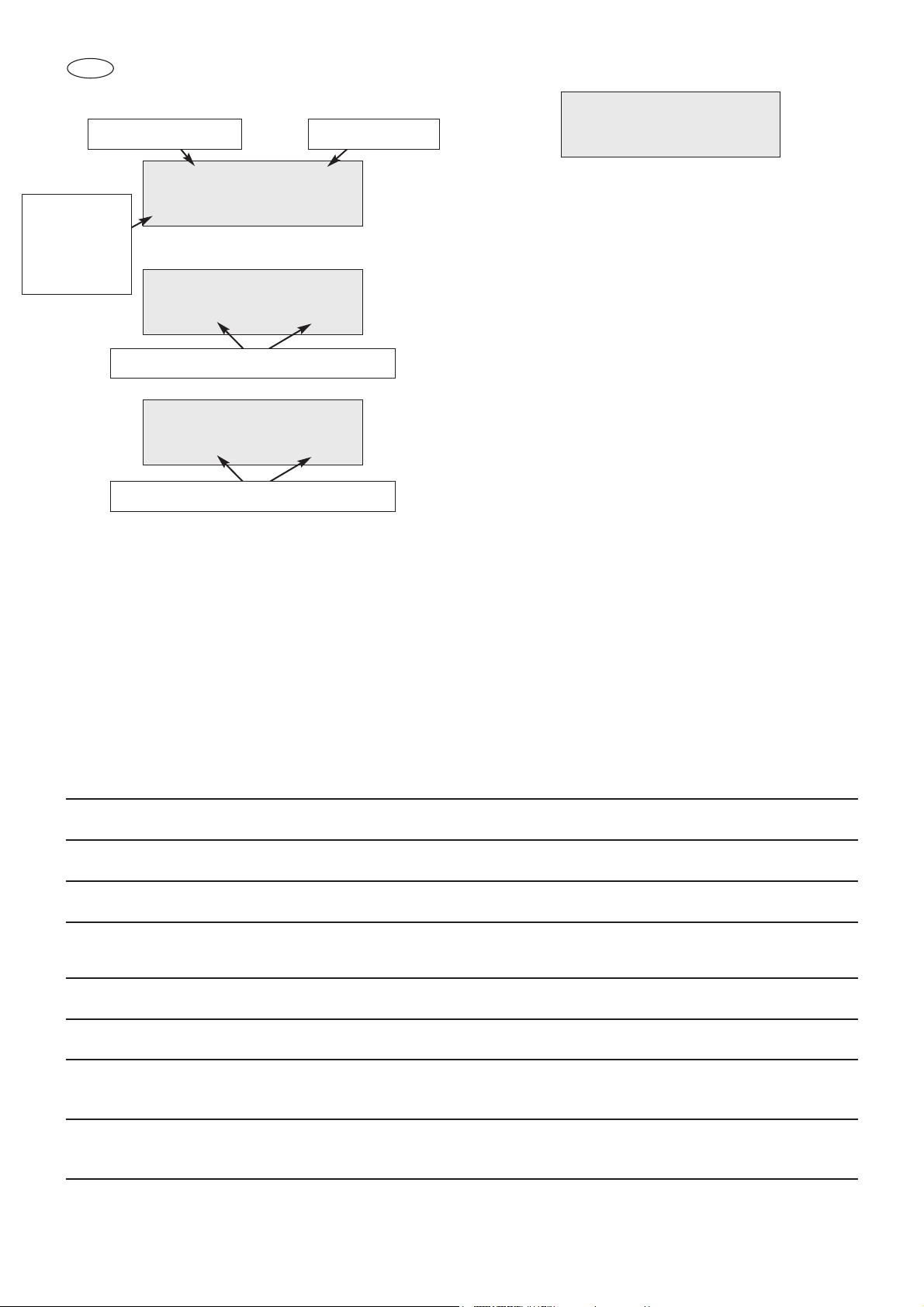
TURNING OFF
ON/OFF
Activation of continuous
operation recirculation
ventilation
Infrared
data receiver
Select the
menu
Decrease the
value
Confirm the entrance to the menu selected
or the value selected
Increase the value
Page 11

11
GB
When the language required is displayed, press
the
ENTER
BUTTON; the controller requests
a second confirmation by displaying EXIT or
CONFIRM.
Press the button to confirm or the
ENTER
button to exit and return to the initial mask.
4.3 Date and time setting
Press the MENU button and with buttons
or
go to MENU 8 SET CLOCK; press
ENTER
and the date and time will be displayed with
the first digit of the day blinking. Modify the digit
with buttons
or and confirm the value
with the
ENTER
button, the new value is
acquired and the month digit blinks next. Repeat
in succession the procedure until the seconds
value is reached , and press the
ENTER
button. The successful acquisition of the values will
be signalled by the flashing date and time.
4.4 Display and setting of the set point
Press the MENU button and with buttons
or
go to the MENU 2 CHANGE mask
SET POINT; press the
ENTER
button; the
temperature set and the temperature to modify is
displayed. Modify the NEW SET temperature
using the button to increase the value by N
degrees and button to decrease the value by
N degrees To memorise the new temperature set,
press the
ENTER
button. The new value will
flash to confirm that it has been memorised.
4.5 Humidity adjustment
(on HC20C only)
Press the MENU and use the
or
buttons
to open the MENU 3 - CHANGE HUMIDITY window; press ENTER; the current humidity level and
the new one to be set will be shown. Use the
or
buttons to change the humidity NEW RH%
and press ENTER to confirm. The value will blink
to confirm it has been accepted.
Humidity values can be varied within an accepted
range of 40% to 90%.
4.6 Door microswitch function
The controller signals the opening of the door and
shows the following mask on the display.
The evaporator fans will stop every time one of
the doors opens and will start again when it closes again. If the door remains open for more than
five minutes, the signalling buzzer is activated
and the fan of the evaporator will start up again as
if it were closed.
4.7 Recirculation fan in continuous opera-
tion (Function not available for model
HC20NT/2 HC20NTV HC20BTV HC20BTV/2
HC40NTV HC40BTV)
Keep the button pressed on ON to activate
the recirculation fan. In this mode the internal fan
remains on in continuous mode independently of
the compressor function.
Press the same button again to deactivate it.
4.8 Restore menu
If the electronic card crashes or because of peaks
or losses of voltage the programming data is lost,
it is possible for the user to load the factoring settings.
Press the MENU button, use buttons
or
to go to the restore menu and press the
ENTER
button; in this way the cabinet model and the
programming number loaded is shown.
Press
ENTER
again and confirm with the but-
ton ; the card turns off and the factory settings
are restored.
DOOR OPEN >>OK
Cell -21°C
NEW SET: -15°C
CURRENT: -15°C
Menu 2
CHANGE SETPOINT
Date: 12/04/03
Time: 11:54:23
Page 12

12
GB
5.1 Manual defrosting
(not available for HC20 BT - BT/2 - NT - NT/2)
It is possible to activate manual defrosting:
press the MENU button move to MENU4
DEFROSTING with buttons
or and
press the
ENTER
button.
The controller requests a further confirmation, displaying EXIT or CONFIRM.
Press the button to confirm or the
ENTER
button to exit and return to the initial mask.
Message with active defrosting:
At the end of the defrosting the compressor starts
again and the display will show the
wording RECOVERY until the set-point temperature is reached.
The defrosting can terminate on reaching the
defrosting setpoint detected by the two sensors
on the evaporator or because a maximum defrosting time has been reached. If the maximum temperature is reached, the controller signals the fault
with the following flashing alarm message and
buzzer:
The controller memorises the type of alarm, date
and time.
To cancel the alarm message, press the
ENTER
button.
The alarm is anyway registered in the controller’s
alarm log.
5.2 Periodic defrosting
(not available for HC20 BT - BT/2 - NT - NT/2)
For all models, the defrosting must be repeated
automatically and at regular intervals starting
immediately after the instrument comes on.
The time elapsing between one automatic defrosting and the next is set in the factory at six hours.
In this case too, the defrosting can terminate
when the end of defrosting temperature detected
by the two sensors on the evaporator is reached
or because a maximum defrosting time has been
reached.
The fault is shown as in the case of manual
defrosting.
5.3 Timed defrosting
(not available for HC20 BT - BT/2 - NT - NT/2)
It is possible to set the start time of four automatic defrostings a day that are always repeated over
the twenty-four hour period. In this way, the automatic periodic defrostings are inhibited.
The defrosting term occurs in the way described
previously.
F18 DEFR. TIME
S 19/02/02 06:09
DEFR. TIME
—> Call SERVICE
RECOVERY >>OK
CELL -10,5°C
DEFROS >>OK
CELL -18°C
Menu 4
DEFROSTING
5. DEFROSTING MANAGEMENT
Page 13

13
GB
6.1 ALARM LOGGING
The controller is fitted with visual and acoustic
alarm signalling determined by machine malfunctions.
The alarms are recorded up to a maximum of sixteen events; further alarms a written over those
already detected.
The alarm is signalled by a buzzer and the type of
alarm is shown on the display.Only the
HIGH/LOW cell temperature alarms have an
alarm signalling delay from the moment they are
detected. It is sixty minutes.
The controller will show the HIGH or LOW temperature prealarm on the display and, at the
end of the time it will log it in the alarm list.
High cell temperature prealarm message
Low cell temperature prealarm message
At the end of the prealarm time the controller will
show the following mask:
To cancel the alarm access MENU1 ALARM LOG
6.2 Silencing alarms
To silence the signalling buzzer during an alarm,
press the
ENTER
button.
6.3 Alarm list
It is possible to see the alarms the controller has
logged while operating.
To enter the display mode press MENU, go to
MENU1 ALARM LOG using buttons
or
and press
ENTER
.
Using buttons
or scroll through all the
alarms logged by the controller. The controller
logs the type of alarm, the date the alarm began
and the time it lasted.
When you press buttons
or together, the
last alarm reset date is shown. The maximum and
minimum temperature alarm also shows the minimum and maximum temperatures achieved.
In the blackout alarm, the date and time of the
beginning of the blackout and the date and time of
end. If no alarms are logged, the controller shows
the message NO EVENTS IN THE LOG.
Example of a high temperature alarm:
AL 27: HIGH TEMP.
Duration 015’
AL 27: HIGH TEMP.
S.=18/03/02 12:29
AL 27: HIGH TEMP.
Max Temp.= +25°C
ALARM DETECTED
CELL -24,0 °C
PAUSE >>Lt
CELL -24°C
COOLING >>Ht
Cell -18°C
6. MANAGEMENT OF THE ALARMS DETECTED
AND TURNING THEM OFF
Page 14
14
GB
6.4 MALFUNCTIONING MESSAGE (they jeopardise machine operation – CALL THE SERVICE
MESSAGE DISPLAY CAUSE CANCELLATION
ERR. SENSOR S1 Flashing Temperature sensor failure Automatic when failure rectified
ERR. SENSOR S2 Flashing Evaporator sensor failure Automatic when failure rectified
ERR. SENSOR S3 Flashing 2ndtemperature sensor failure Automatic when failure rectified
PROBE L1 ERR. Flashing Humidity probe fault Automatic when fault reset
(HC20C only)
DEFR TIME Flashing Long defrosting time Press ENTER
COMP. USE Flashing Operating time Press ENTER long compressor
LOW EVAP T Flashing Evaporator temperature Press ENTER when failure rectified
less than set point
PROTECTION Flashing Max pressure switch cut-in Rearm high pressure pressure switch
or max thermostat Turn off and restart the control
Example of a blackout alarm:
In the case of HIGH/LOW temperature
alarms, before being registered a prealarm
time of sixty minutes is calculated; at the end
of this time the controller logs the alarm in the
alarm log and shows the following mask on
the display:
To eliminate the indication go into the alarm
log as shown in the paragraph above.
6.4 Serious alarm list
SERIOUS alarms can determine the incorrect
functioning of the conservator.
The display is the same as that described for
the alarms and the signalling buzzer is activated. To silence the buzzer, press the
ENTER
button.
The cancellation is automatic when the malfunction is rectified, the alarm is however
logged in the ALARM MENU.
IMPORTANT!
CONTACT AN AUTHORISED
TECNOMAC CENTRE
IN THE CASE OF A SERIOUS ALARM.
ALARM DETECTED
CELL -24,0 °C
AL 26: BLACK OUT
S 15/03/02 10:01
AL 26: BLACK OUT
B 15/03/02 10:22
AL 26: BLACK OUT
Max Temp.= +12°C
Maximum
temperature
reached
during the
blackout
Number of alarms Alarm type
Date and time the blackout finished
Date and time the blackout started
Page 15

15
GB
SIGNALLING MESSAGES (they do not jeopardise the functioning of the machine)
MESSAGE DISPLAY CAUSE CANCELLATION
>>HT FIXED high temp prealarm Automatic rectification
>>LT FIXED low temp prealarm Automatic rectification
ALARM DETECTED FIXED logging of a Remove the cause of the
alarm
alarm in the log and enter into MENU 1 alarm
log to reset the controller
SET CLOCK loss of clock data Set clock data
6.5 List of any other malfunctions that cannot be signalled:
PROBLEM CAUSE SOLUTION
The compressor does not function 1 – Loss of power 1 – Check the connection with the electricity line
The fans do not turn 1 – Loss of power 1 – Check the connection with the electricity line
2 – Fan failure 2 – Intervention of technician for replacement
3 – Condenser in operation failure 3 – Intervention of technician for replacement
4 – Protection fuse broken 4 – Intervention of technician for replacement
The electronic card does 1 – Loss of power 1 – Check the connection with the electricity line
not come on 2 – Protection fuses broken 2 – Intervention of technician for replacement
The compressor works but 1 – No refrigerating gas 1 - Intervention of technician
does not cool the cell 2 – Condenser dirty 2 – Clean the condenser
Page 16

16
GB
The information and instructions in this chapter are for those who work on the machine:
the user, the maintenance engineer and also
non-specialised personnel.
All cleaning and maintenance operations
must be done after disconnecting the
power supply from the system.
7.1 ELEMENTARY SAFETY STANDARDS
To carry out all the cleaning and servicing
operations in full safety.
we draw your attention to the following
safety standards.
- do not touch the machine with wet or
damp hands or feet.
- do not operate the machine with bare
feet.
- do not insert screwdrivers, kitchen utensils or anything else between the guards
and the moving parts.
- before carrying out cleaning or servicing
operations, disconnect the machine from
the electricity mains, turn off at the
ON/OFF switch and remove the plug.
- do not pull the power lead to disconnect
the machine from the mains.
Removing protective and safety devices
must not be removed under any circumstances to carry out ordinary maintenance operations. The manufacturer
declines all liability for accidents caused
through a failure to comply with this obligation.
Before starting up the machine it is necessary to thoroughly clean the inside of
cell.
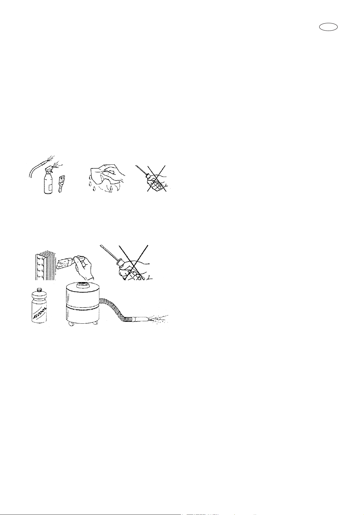
7.2 CONDENSER CLEANING
For the correct and efficient functioning of
the condenser, it is necessary for the air
condenser to be kept clean to allow the
free circulation of the air. This operation,
to be undertaken every thirty days at the
most can be performed with non-metallic
brushes in order to remove all the dust
and the down from the fins of the condenser itself.
You are advised to use a vacuum cleaner in order not to spread removed dust
around the environment. If there are
greasy deposits, eliminate them with a
paint brush soaked in alcohol.
DO NOT SCRAPE THE SURFACES WITH
POINTED OR ABRASIVE BODIES.
THIS OPERATION MUST BE CARRIED
OUT WITH THE SYSTEM AT A STANDSTILL.
CAUTION
The condenser has sharp edges.
While undertaking the abovementioned operations, always wear protective gloves, glasses and masks to protect the breathing apparatus.
7. ORDINARY MAINTENANCE
CCAAUUTTIIOONN !!!!!
!
THIS OPERATION MUST ONLY BE
CARRIED OUT BY A
LICENSED INSTALLATION ENGINEER.
Page 17
17
GB
7.3 CELL CLEANING
In order to ensure hygiene and protect
the quality of the foodstuffs treated, the
inside of the cell must be cleaned frequently, depending on the type of foods
conserved.
Weekly cleaning is recommended.
The conformation of the cell and the
internal components permit them to be
washed using a cloth or sponge.
For the cleaning of the unit cabinet use a
soft cloth with a mild detergent solution
specific for Stainless Steel.
N.B. always use protective gloves when
cleaning.
7.4 DRAINAGE OF DEFROSTING
WATER .
The system has a facility for automatic
and manual defrosting when necessary.
Check the correct evaporator water
drainage ensuring there are no obstructions in the drainage pipe.
Page 18

Via del Lavoro, 9 - C.P. 172
I - 31033 Castelfranco Veneto (TV) Italy
Tel. +39.0423.738451
Fax. +39.0423.722811
E-mail: tecnomac@castelmac.it
Web-site: www.castelmac.it
Cod. 71503647/0 - Rev.002 - 02/2008
ISO 9001
Cert. N° 0412/2
 Loading...