

HEADLIGHT TESTER
ART. 12066
MANUAL FOR USE
AND MAINTENANCE


2
INDEX
ACCEPTANCE OF THE MACHINE .......................................................... 4
FOREWORD ............................................................................................. 4
TECHNICAL DATA ................................................................................... 4
SYMBOLS USED IN THE MANUAL ......................................................... 5
SYMBOLS USED ON THE MACHINE...................................................... 6
PREPARATION OF THE MACHINE ......................................................... 7
HANDLING CRATED MACHINE ..................................................................................... 7
CONTENTS OF THE PACKAGE .................................................................................... 7
DESCRIPTION OF THE MACHINE .......................................................... 8
GENERAL SAFETY RULES ................................................................... 11
ASSEMBLY ............................................................................................. 12
1 – ASSEMBLY OF BOTTOM PART OF THE COLUMN ON THE BASE .......................12
2 – ASSEMBLY OF THE OPTICAL BOX SLIDING SYSTEM ON THE COLUMN .........13
3 – ASSEMBLY OF THE TOP HALF PART OF THE COLUMN .....................................13
4 – ASSEMBLY OF THE OPTICAL BOX ON THE COLUMN .........................................13
5 – ASSEMBLY OF THE VISOR ON THE COLUMN......................................................14
6 – LEVELING OF THE MACHINE .................................................................................14
PREPARATION ....................................................................................... 15
PREAPARATION OF THE VEHICLE .............................................................................15
WORKING SURFACE ....................................................................................................15
ALIGNMENT WITH THE VEHICLE ........................................................ 16
POSITIONING ................................................................................................................16
ALIGNMENT WITH LASER POINTER (optional) ...........................................................16
ALIGNMENT WITH MIRROR VISOR .............................................................................17
ALIGNMENT WITH THE VEHICLE ................................................................................17
HEADLIGHT TEST .................................................................................. 18
ADJUSTMENT ...............................................................................................................18
LOW BEAM TEST ..........................................................................................................18
HIGH BEAM TEST .........................................................................................................18
FOG LIGHT TEST ..........................................................................................................19
SUPPLEMENTARY INSTRUCTIONS..................................................... 20
REPLACEMENT OF LASER VISOR BATTERIES .........................................................20
BATTERIES REPLACEMENT – DIGITAL VERSION .....................................................20
CLEANING AND MAINTENANCE ..................................................................................20
DEMOLITION AND DISPOSAL ......................................................................................20
WARRANTY ............................................................................................ 21

3

4
ACCEPTANCE OF THE MACHINE
At the time of delivery it is essential to check at once and make sure you have received all the
material indicated in the shipping documents, and that the machine has not undergone damage
during shipment. In this case, show the damage to the forwarder and inform our customer service
department. Only if you proceed promptly in this way will it be possible to obtain any missing
material and reimbursement of the damage.
FOREWORD
This is a device designed for correct beam alignment of any type of automobile or motor vehicle
headlight. The machine must be used for this purpose only. Even the finest of machines can
function properly and ensure profitable service only if it is used correctly and kept in the best
possible condition. For this reason, we ask you to read this manual with care and to reread it
whenever difficulties should arise in using the machine. In case of need, we remind you that our
service centers, organized in cooperation with our retailers, are always at your disposal for any
advice you may need.
NOTE: the manufacturer may decide to make changes in the device without notice, in order to
adapt it to technological advances and specific production or installation needs. Therefore, even if
the illustrations shown in the manual differ slightly from the machine in your possession, the safety
and instructions about it are guaranteed.
TECHNICAL DATA
U/M
Width mm 580
Lenght mm 712
Height mm 1810
Weight kg 20
Power supply for digital display model V d.c. 9
Unity of intensity measurement
klux/1m 0-150
kcd 0-150
lux/25m 0-240
Vertical deviation % 0 -4
Horizontal orientation cm/10m +/-5
Packaging dimensions cm (BxLxH) 80x60x50
Packed product weight kg 22

5
SYMBOLS USED IN THE MANUAL
Warning symbol
Read the sections preceded by this symbol with particular care, for the safety of the
operator and the machine.

6
SYMBOLS USED ON THE MACHINE
Laser beam
Read with care warnings with this symbol for operator safety and machine safety.
Pay attention of all warning symbols on the products, keep
wholly stickers and fully readable.

7
PREPARATION OF THE MACHINE
HANDLING CRATED MACHINE
The machine is packed in a special crate.
Do not stack more than four crates.
The packed weight is 20 kg.
The external dimensions are:
B: 800 mm
L: 600 mm
H: 500 mm
CONTENTS OF THE PACKAGE
N°1 base
N°1 column (2 parts)
N°1 sliding system
N°1 visor
N°1 carton containing:
an optical chamber with n°2 screws for fastening the structure
a package containing n°4 screws and n°4 nuts for fastening column to the structure
manual for use and maintenance
conformity certificate
If you receive erroneous parts, or notice shortages or damage, contact the distributor. Keep
the package, including the original packing material, in case you need to send the product for
repairs.

8
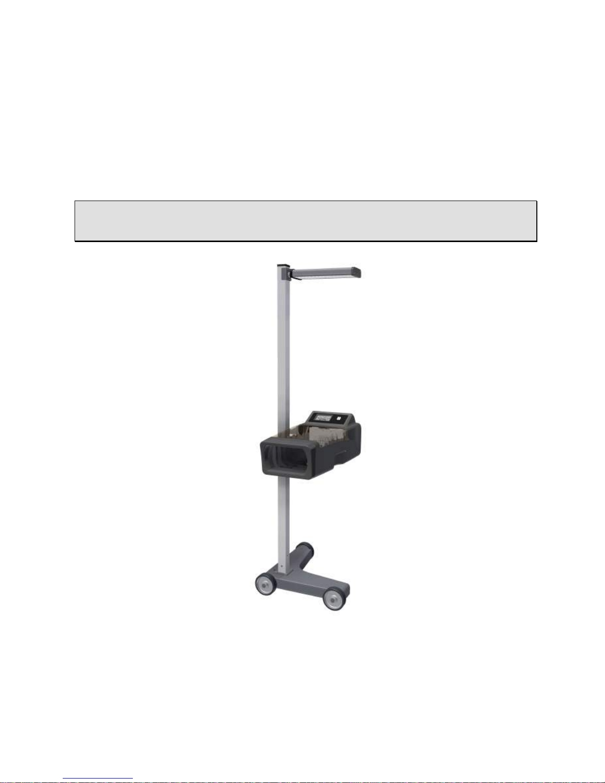
DESCRIPTION OF THE MACHINE
The headlight tester is a device that allows to test
headlights of all types, for motor vehicles, cars
and trucks in general.
The machine can be installed as a moving station
on rubber wheels.
The optical box is adjustable in height by
means of a slider on precise, silent, plastic
runners on an aluminum column marked with a
centimeter scale for exact positioning in
connection with the headlight.
If equipped with laser pointing system, on the side
of the optical box, there is a switch turning on the
laser pointer to allow exact positioning with the
centre of the headlight.

9
DESCRIPTION OF THE MACHINE
Art. 12066 e Art.12066/S
Analogic unit is equipped with a luxmeter with 3
intensity marker ranges:
• upper range indicates lux/25m values (lux at
25 meters)
• central range indicates klux/1m values (kilo
lux at 1 meter and kcd (kilo candles)
• coloured range on lower side quickly and
intuitively indicates if light intensity of high
beam is good or not good enough.
On the side of the luxmeter there is a switch to
select which beam you want to read.
Art. 12066/D
The unit is equipped with a LCD display, to
indicate light intensity, and a switch to select beam
you want to read.
On backside there is a knob with graduated range
to position control panel in connection to the
desired inclination to verify beams properly
Inside optical box a printed graduated panel allows
to verify exact position of high/low/fog beam.
Vertical lines indicate degrees of horizontal
orientation of low beam.
Horizontal lines are useful to verify or regulate
correct inclination.

10
DESCRIPTION OF THE MACHINE
The visor that facilitates the alignment of the
device to the vehicle can be equipped with
mirror or laser.

11
GENERAL SAFETY RULES
The following rules must be followed carefully to prevent damage to the
operator and machine.
Read the machine labels, do not cover them for any reason, and replace them immediately if
they should be damaged.
The device should only be used by authorized personnel, trained in its use.
Do not use the device in an explosive atmosphere.
The working environment should be dry and sufficiently ventilated.
When moving the machine, pay attention to other people, especially children, in the vicinity.
Do not bump shelves or scaffoldings where there may be a danger of falling objects: you and
the machine could be damaged.
The storage temperature should be between -5° and +55°C.
The working temperature should be between +5° and +45°C.
Provide an adequate exhaust system for the exhaust gas, since the headlight test must be
performed with the engine of the motor vehicle running. Accidental inhalation of carbon
monoxide can cause serious damage to the organism, with a fatal outcome in some cases.
Contact our agent in your zone, who can indicate the most suitable system for your company.
Do not leave the headlight tester in the sun or in the immediate vicinity of hot objects like
heaters, radiators, etc.
Do not leave the headlight tester out in the rain or in an excessively damp place as its
electronic circuits could be damaged.
If the headlight tester will not be used for a long period, we recommend that you cover it with
its dust cover (optional).
There is a battery in the headlight tester that could cause a fire or explosion hazard if handled
improperly. To prevent this risk to not heat or use open flames near the battery and, when
replacing it, use one with the same characteristics.
When you encounter any malfunction in use of the machine, contact the retailer or send the
machine to the nearest service center.
In case of parts replacements, order ORIGINAL replacement parts from a concessionaire or
authorized retailer.
Tampering with any part of the machine will invalidate the warranty.

12
ASSEMBLY
Open the packaging from the top extracting all
parts taking care not to cause violent shocks and
damages.
1 – ASSEMBLY OF BOTTOM PART OF THE
COLUMN ON THE BASE
Bottom half part of the column is already
preassembled with the fixing plate on the base.
Be careful to orient the column with the graduated
scale in the direction of the two in-line wheels of
the base as indicated in the picture aside.
Fix the bottom half part of the column on the base
through four screws and nuts supplied with the
unit as shown in picture
13
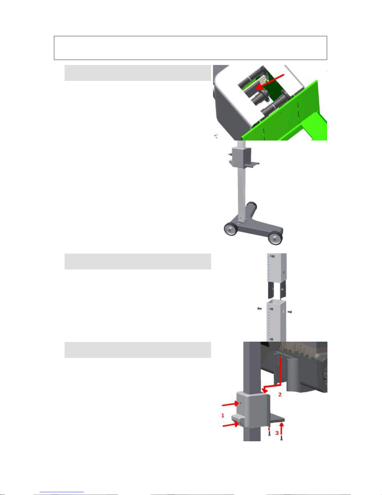
ASSEMBLY
2 – ASSEMBLY OF THE OPTICAL BOX
SLIDING SYSTEM ON THE COLUMN
Insert the sliding system of the optical box on the
bottom part of the column already fixed on the
base. In order to facilitate the insert of the sliding
system, keep pressed the locking position lever.
Be careful to the correct positioning of the brake
pad of the sliding system, respecting the correct
direction as indicated in the picture aside.
3 – ASSEMBLY OF THE TOP HALF PART OF
THE COLUMN
Mount the top part of the column inserting the
brackets already assembled into the other part of
the column and fix the brackets with the screws
supplied. Pay attention to mount the two pieces of
the column aligning them in the same direction of
the graduated scale, as indicated in the picture.
4 – ASSEMBLY OF THE OPTICAL BOX ON
THE COLUMN
Extract from the package the optical box, loosen
the fixing screws (1) of the sliding system cover,
insert the optical box (2) from the top into the
position of the column sliding system, until it is
completely into place. Fix the optical box to the
sliding system through the screws supplied, from
the bottom part of the optical box (3). Tighten the
fixing screws of the sliding carter (1).

14
ASSEMBLY
5 – ASSEMBLY OF THE VISOR ON THE
COLUMN
The visor has been calibrated during testing
procedures, therefore it is not necessary to
recalibrate it when it has to be assembled.
• Insert the fixing screw, the spring and the washers
into the column as indicated in the picture aside.
• Position on the opposite side the adjusting plate precalibrated.
• Screw the visor up to tighten completely
6 – LEVELING OF THE MACHINE
In order to carry out a correct measurement and
adjustment, the headlight tester has to be leveled. The
unit is always leveled during production process and
testing procedure before shipment. If the floor of the
working area is not leveled, please follow the
instructions below:
Inside the optical box there’s a bubble level and the
base has a rear wheel and the farthest wheel from the
column, both adjustable.
• Locate the headlight tester in the working area
• Lower the optical box until the lowest point possible
• Loosen slightly the fixing screw of the wheel (1)
• Through the upper screw, adjust the inclination (2)
until the bubble is inside the reference circle.
• Tighten the fixing screw of the wheel (3)
• Check once again the bubble inside the optical box.

15
PREPARATION
PREAPARATION OF THE VEHICLE
Make sure the headlights are clean and dry. If the vehicle is equipped with a headlight aligner, set
in on “0”. Eliminate anything that could affect the correct position of the vehicle: mud, snow, ice,
etc. Straighten the car wheels. Make sure the vehicle does not have any distortions of the frame.
Make sure the tires are inflated at the correct pressure. Start the engine and perform the test. In
case of vehicles with pneumatic suspension, start the engine five minutes before starting the test
and proceed with the engine running.
CAUTION!
When operating in an enclosed space with the engine on it is essential to evacuate the toxic
gasses produced by combustion. We recommend using a specific fan for exhaust fumes.
WORKING SURFACE
During the headlight test the floor surface must be
level. If this is not possible, the headlight tester
should be positioned on a surface with a uniform
slope, in any case not exceeding 0.5%.
Do not test headlights on floors that are not perfectly
regular and level, as the measurement might not be
accurate.

16
ALIGNMENT WITH THE VEHICLE
POSITIONING
Place the headlight tester in front of the right headlight
of the vehicle at a distance of about 20 cm, measure
the height from the floor at the center of the headlight
and adjust the optical chamber at the corresponding
height using the graduated scale on the column.
As index of the scale, please use the upper part of
the slider runner.
ALIGNMENT WITH LASER POINTER
(optional)
Switch on the laser through the red button on the
lateral side of the optical box. From the centre of the
lens, a laser ray will allow to find the centre of the
beam. Once the alignment process is completed
switch off the laser to avoid a fast batteries
discharge.
CAUTION!
During this operation, do not look directly the
laser ray and make sure that this is not directed
at persons nearby the working area.

17
ALIGNMENT WITH THE VEHICLE
ALIGNMENT WITH MIRROR VISOR
Locate two details on the front of the vehicle that are
perfectly symmetrical between them (for example the
top of the windshield or the headlights themselves).
Turn the optical chamber until, when you look in the
mirror, the two reference points meet the black line
stenciled on the mirror.
ALIGNMENT WITH THE VEHICLE
The operator and designer of the working area must
be aware of the risks deriving from the laser. The
island must not be located in a transit zone and must
be well marked and outlined by a yellow line, and
possible enclosed with special barriers.
Make sure there are no people in the test zone, turn
the visor downward and switch it on.
Locate two details on the front of the vehicle, such as
the headlights themselves, turn the optical chamber
until the two reference points meet the line projected
by the visor and block the column.
CAUTION!
Switch off the laser immediately before proceeding with the other operations of control and
possible adjustment of the headlight.
The laser line is in class 3A with a wave length of 650 nm (nanometers) and a power of 3 mW
(milliwatts) which means that even only direct observation of the beam with the use of amplifying
optical devices such as binoculars can be hazardous. Accidental exposure is not considered
hazardous as, since it is in the visible range, the eyelid reflex does not permit an exposure of more
than 0.25 sec.

18
HEADLIGHT TEST
ADJUSTMENT
Inside the motor compartment, read at the top of
the headlight the tilt indicated by the manufacturer,
e.g. 1.2%, and turn the knob on the rear part of the
optical box as indicated.
If there is no indication by the manufacturer, comply with
the laws in force in your country.
LOW BEAM TEST
Check the position of the low beam headlight projection
on the control panel inside the optical box.
If the light-dark division line on the left is aligned to the
horizontal line printed on the panel, this means that
inclination is correct. If it is not correct, adjust the beam
through the screw on the motor compartment.
If the light-dark division area is aligned to the inclined
line printed on the panel, this means that horizontal
orientation is correct. If it is not correct, adjust the beam
through the screw on the motor compartment. Only
when the beam is correctly aligned, press on the switch
with the low beam symbol and read and check if light
intensity on the luxmeter complies with the limits of the
laws in force.
HIGH BEAM TEST
Proceed and centre the high beam projector if different
from the the low beam.
Check the position of the high beam headlight
projection on the control panel.
Maximum light intensity zone has to be centered or
inside the square in the middle of the panel.
If the two optical groups have separated adjustments,
adjust the position through the screws on the motor
compartment. If not, check the position of the lamp or
adjust the position through the screws on the motor
compartment.
Only when the beam is correctly aligned, press on the
switch with the high beam symbol and read and check if
light intensity on the luxmeter complies with the limits of
the laws in force.
IMPORTANT: If you performed an adjustment, verify
once again the low beam position to ensure that its
position is ok.

19
HEADLIGHT TEST
FOG LIGHT TEST
If present, displace and centre the headlight tester on
the the fog beam projector. On the the headlight tester
turn the knob on the rear part of the optical box
according to the manufacturer indications.
If there is no indication by the manufacturer, comply
with the laws in force in your country.
Check the position of the fog beam headlight projection
on the control panel inside the optical box.
The division line between dark and light has to be
aligned to the horizontal line printed on the panel and
the projection has to be aligned in connection with the
centre, if not aligned, proceed with the adjustment
through the adjusting screws. La linea di divisione
superiore luce-buio deve essere allineata alla linea
orizzontale serigrafata e la proiezione deve essere
allineata rispetto al centro,; se non lo è, regolare il
proiettore mediante le viti di regolazione.

20
SUPPLEMENTARY INSTRUCTIONS
REPLACEMENT OF LASER VISOR BATTERIES
Unscrew the two screws on the cover of the laser visor
and replace the 3 penlight batteries size AA 1.5V,
respecting the correct polarity, close the visor and
fasten the cover with the screws provided.
BATTERIES REPLACEMENT – DIGITAL
VERSION
If it is necessary to replace the battery of the
headlight tester, proceed as follows:
Use a Phillips screwdriver to remove the screw fastening
the battery support to the bottom of the optical box.
Remove the support and take the battery out, take off the
connector and replace the battery.
Reassemble, proceeding in reverse order performing the
operations described for disassembly.
CLEANING AND MAINTENANCE
The machine does not require particular maintenance other than normal cleaning with a damp cloth (water
or normal detergent).
CAUTION! Do not use nitro solvents.
DEMOLITION AND DISPOSAL
The machine is mainly composed of steel.
Other parts:
in plastic, the optical box and some parts
in aluminum, the column
in cardboard and paper, packing and documents.
The machine is painted with scratch-resistant epoxy powder.
In disposing of the machine, comply with the provisions of the local authorities.

21
WARRANTY
At the time of delivery it is essential to check at once and make sure you have received all
the material indicated in the shipping documents, and that the machine has not undergone
damage during shipment. In this case, show the damage to the forwarder and inform our
customer service department. Only if you proceed promptly in this way will it be possible to
obtain any missing material and reimbursement of the damage.
In case of evident and acknowledged manufacturing defects of any product, it will be
repaired or replaced under the warranty only if the claim is made and documented within 8
days of delivery. Returns of defective goods will be accepted only FREIGHT PREPAID,
while all returns carriage forward will be rejected. All other forms of reimbursement are
excluded.

22

23

24
 Loading...