

Tecnologic TT 73 Operating Instructions Manual
TT 73
MICROPROCESSOR-BASED
DIGITAL ELECTRONIC TIMER
INDEX
7.3
INSTRUMENT DESCRIPTION1
GENERAL DESCRIPTION1.1
FRONT PANEL DESCRIPTION1.2
PROGRAMMING2
SET POINT PROGRAMMING 2.1
PARAMETERS PROGRAMMING2.2
PARAMETERS LOCK2.3
INSTALLATION AND USE ADVICES3
USE ALLOWED3.1
MECHANICAL MOUNTING3.2
ELECTRICAL CONNECTIONS3.3
ELECTRICAL CONNECTION DRAWING3.4
OPERATING MODE4
COMMANDS OPERATING MODE4.1
DISPLAY OPERATING MODE4.2
OUT 1 OPERATING MODE4.3
OUT 2 OPERATING MODE4.4
CNT EN INPUT OPERATING MODE4.5
PROGRAMMABLE PARAMETERS5
PARAMETERS TABLE5.1
PARAMETERS DESCRIPTION 5.2
TROUBLES, MAINTENANCE, WARRANTY6
CLEANING6.1
WARRANTY AND REPAIRS6.2
TECHNICAL DATA7
ELECTRICAL DATA7.1
MECHANICAL DATA7.2
MECHANICAL DIMENSIONS, PANEL CUT OUT AND
FIXING DEVICE
FUNCTIONAL DATA7.4
INSTRUMENT CODE7.5
OPERATING INSTRUCTIONS
Vr. 01 (ENG) - cod.: ISTR 06083
TECNOLOGIC S.p.A.
VIA INDIPENDENZA 56
27029 VIGEVANO (PV) ITALY
TEL.: +39 0381 69871
FAX: +39 0381 698730
internet : http:\\www.tecnologic.it
e-mail: info@tecnologic.it
PREVIOUS STATEMENT:
In this manual are contained all the necessary information for a
correct installation and the instructions for the use and the
maintenance of the product; we recommend, therefore, to read
carefully the following instructions.
The maximum care has been used in the realisation of this
document, anyway TECNOLOGIC S.p.A. does not assume any
responsibility deriving from the use of itself.
The same consideration has to be done for each person or
Company involved in the creation of this manual.
The herewith issue is an exclusive property of TECNOLOGIC
S.p.A. which forbids any reproduction and divulgation, although
partial, if not expressly authorised.
TECNOLOGIC S.p.A. reserves the right to execute aesthetically and
functional modifications, at any moment and without any notice.
1 - INSTRUMENT DESCRIPTION
1.1 – GENERAL DESCRIPTION
TT 73 is a programmable microprocessor based timer with 1or 2
outputs.
The instrument offers the possibility to program: up to 3 set points
time, 5 operating modes for the output OUT1, 4 operating modes for
the output OUT2, 4 time scales (from 9999 hrs. maximum to 0.1
sec. minimum), 4 functioning modes of counting enable and 2
counting modes (UP or DOWN).
The instrument can have an inside back up battery (optional) which
permits the counting also without power supply.
The counting state is visualised on 4 digits display while the outputs
state is signalised by a led.
The instrument can have 2 outputs (relay or to drive solid state
relays) and 2 digital inputs for count enable (CNT EN) and reset
(RES) which can be for free voltage contacts or voltage signals (the
same voltage supply value).
The programming of the instrument is possible by means of the 3
keys placed on the front while the counting is possible using the
frontal key START/STOP or using the back inputs CNT EN and
RES.
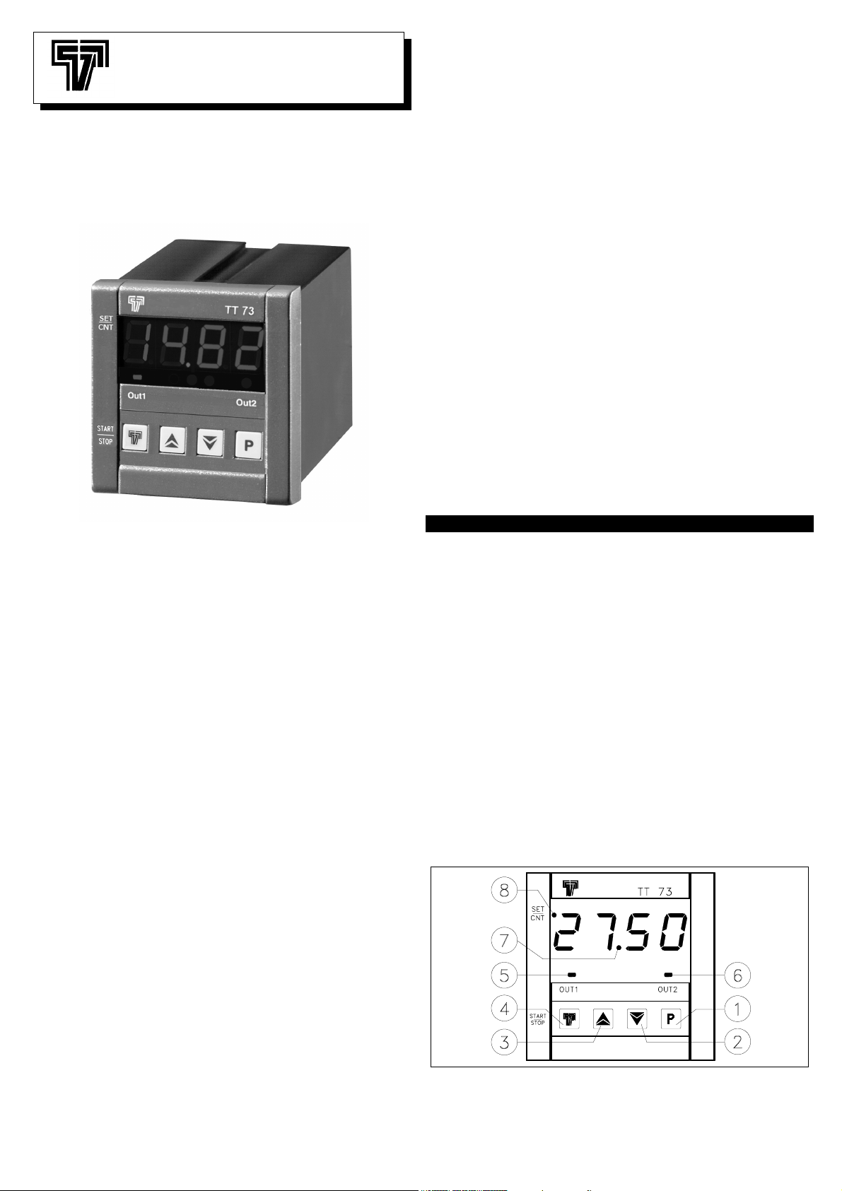
1.2 - FRONT PANEL DESCRIPTION
1 - Key P : Used for the set point setting and to program the
functioning parameters
TECNOLOGIC spa - TT 73 - OPERATING INSTRUCTIONS - Vr. 01 - ISTR 06083 - PAG. 1

2 - Key DOWN : Used to decrease the values or to select
parameters
3 - Key UP : Used to increase the values or to select parameters
4 - Key T (Start/Stop) : Used to Start, Stop or reset the count
5 - Led OUT 1 : It indicates when the output OUT1 is on or off.
6 - Led OUT 2 : It indicates when the output OUT2 is on or off.
7 - Led separator : It indicates the separation between hours and
minutes, minutes and seconds or seconds and cents.
8 - Led SET/CNT : Signalize the set point or the parameters
programming mode (flashing fast), the count on (flashing each
second), the count stopped (on) or reset mode (off).
2 - PROGRAMMING
2.1 – SET POINTS PROGRAMMING
The instrument permits to program up to 3 time sets: “t1”, “t2”,
“t3”.
To program this times do proceed as follows :
Pushing key P and keeping it pushed for 1 sec. approx., the display
will visualize “t1” and led SET/CNT will blink rapidly.
Releasing the key, on the display will be visualized the programmed
Set Point “t1”.
To modify it, work on keys UP, to increase the value or on key
DOWN, to decrease it.
If the programmed functioning mode require the set “t2” (F1 = 3, 4
or 5), for programming this pressing key P again and the display will
show “t2”.
Releasing the key, on the display will be visualized the programmed
Set Point “t2” and will be possible to modify it by the key UP or
DOWN.
If the programmed functioning mode require the set “t3” (F2 = 3 o
4), for programming this pressing key P again and the display will
show “t3”.
Releasing the key, on the display will be visualized the programmed
Set Point “t3” and will be possible to modify it by the key UP or
DOWN.
The outgoing from the set points programming it’s automatically
obtainable not working on any key for 5 sec. approx. or pressing
only one time the key T, thus the counting value willl again be
displayed.
The programming of the set times is always possible, both with
counting on or off.
2.2 – PARAMETERS PROGRAMMING
To have access at the functioning parameters, it’s necessary to
push key P and keep it pushed for 5 sec. approx.
After 4 sec. will appear the label of the first parameter ("F1").
Now it possible to release key P and it will appear the value
programmed for parameter "F1".
To modify this value work on keys UP or DOWN.
Once the desired value has been programmed, pushing again key P
the display will show the label of the successive parameter.
Releasing then key P, it will appear the value programmed for that
parameter which can be modified working on keys UP and DOWN.
Pushing and releasing key P it’s possible to visualize all the
parameters labels (when key is pushed) and the relative
programming (when key is released) one after the other.
The outgoing from the parameters programming it’s obtainable not
working on any key for 20 sec. approx. or pressing only one time the
key T, thus the counting value willl again be displayed.
P.A.:
During the counting is not possible to enter in the parameters
programming mode.
2.3 – PARAMETERS LOCK
It’s possible to lock the access at the programming parameters with
the following procedure :
Switch off the instrument, push key P and keep it pushed while the
instrument is switched on again.
After approx. 5 sec. on the display will appear "uL" (unlock) which
indicates that the parameters are accessible.
Keeping pushed key P and pushing key DOWN it will appear "Lo"
(lock) which indicates that the parameters are not accessible.
Release key P to exit from this modality.
The display will go back to the normal functioning, the parameters
will not be accessible anymore and it will only be possible to modify
the Set Point.
To have again access at the parameters, repeat the same
procedure pushing key P and selecting "uL" ; finally go out from the
parameters lock modality.
3 - INSTALLATION AND USE ADVICES
3.1 – USE ALLOWED
The instrument has been projected as measure and
control device, built according to EN61010-1 for the
altitudes operation until 2000 ms.
The use of the instrument for applications not
expressly allowed by the above mentioned rule has
to foreseen proper protection devices.
The instrument CAN’T be used in environments with dangerous
atmosphere (flammable or explosive) without a proper protection.
It has to be reminded that the user has to take care that the
electromagnetic rules are being respected also after the instrument
installing, eventually using proper filters.
Whenever a failure or a bad functioning of the instrument may
cause dangerous situations or damage to people, things or animals
it has to be reminded that the plant has to be equipped with
additional electromechanical devices in order to grant the safety.
3.2 – MECHANICAL MOUNTING
The instrument, in DIN case 72 x 72 mm, is designed for flush-in
panel mounting.
Make a hole 66,5 x 66,5 mm and insert the instrument, fixing it with
the provided special brackets.
We recommend to mount the gasket to obtain the front protection
degree as declared. Do avoid to place the instrument in ambient
with very high humidity or dirt that may create condensation or
introduction into the instrument of conductive substances.
Ensure the adequate ventilation to the instrument and avoid the
installation within boxes where are placed devices which may
overheat or have as a consequence the instrument’s functioning at
higher temperature than allowed and declared.
Connect the instrument as far as possible from source of
electromagnetic disturbances so as motors, power relays, relays,
electrovalves,etc.
3.3 – ELECTRICAL CONNECTIONS
Carry out the electrical wiring connecting only one wire for each
terminal , according to the following diagram, checking that the
power supply is the same as indicated on the instrument and the
loads current is not higher than the maximum current admitted.
The instrument, being a built in equipment with permanent
connection into a cabinet, is not equipped neither with switches nor
with internal devices protecting from overcurrent : the installation
shall employ a two-phase circuit-breaker, placed as near as
possible to the instrument, located in a position easily reachable by
the user and marked as instrument disconnecting device.
It's recommended, furthermore, to properly protect all the electric
circuits connected to the instrument, with devices (ex. fuses)
proportionate to the circulating currents.
It's strongly recommended to use cables with proper insulation,
according to the working voltages and temperatures.
Furthermore, the input cable of the probe has to be kept separate
from line voltage wiring. If the input cable of the probe is screened, it
has to be connected on the ground with only one side.
When you choose the "b" parameter with option 2 (timer goes on
operating in case of power failure) is necessary to check that the
inside battery is present and enable.
With the purpose to prolong its duration it recommends him to
disconnect the battery when it is not necessary to the operation.
Finally, it is advisable to check that the parameters are those
desired before connecting the outputs to the actuators in order to
avoid plant anomalies which may cause injuries to people, things or
animals.
Tecnologic S.p.A. and its legal representatives are not
responsible for any eventual damages to people, things or
TECNOLOGIC spa - TT 73 - OPERATING INSTRUCTIONS - Vr. 01 - ISTR 06083 - PAG. 2
animals deriving from the instrument violation, not proper or
wrong use or in any case not in accordance with the instrument
features.
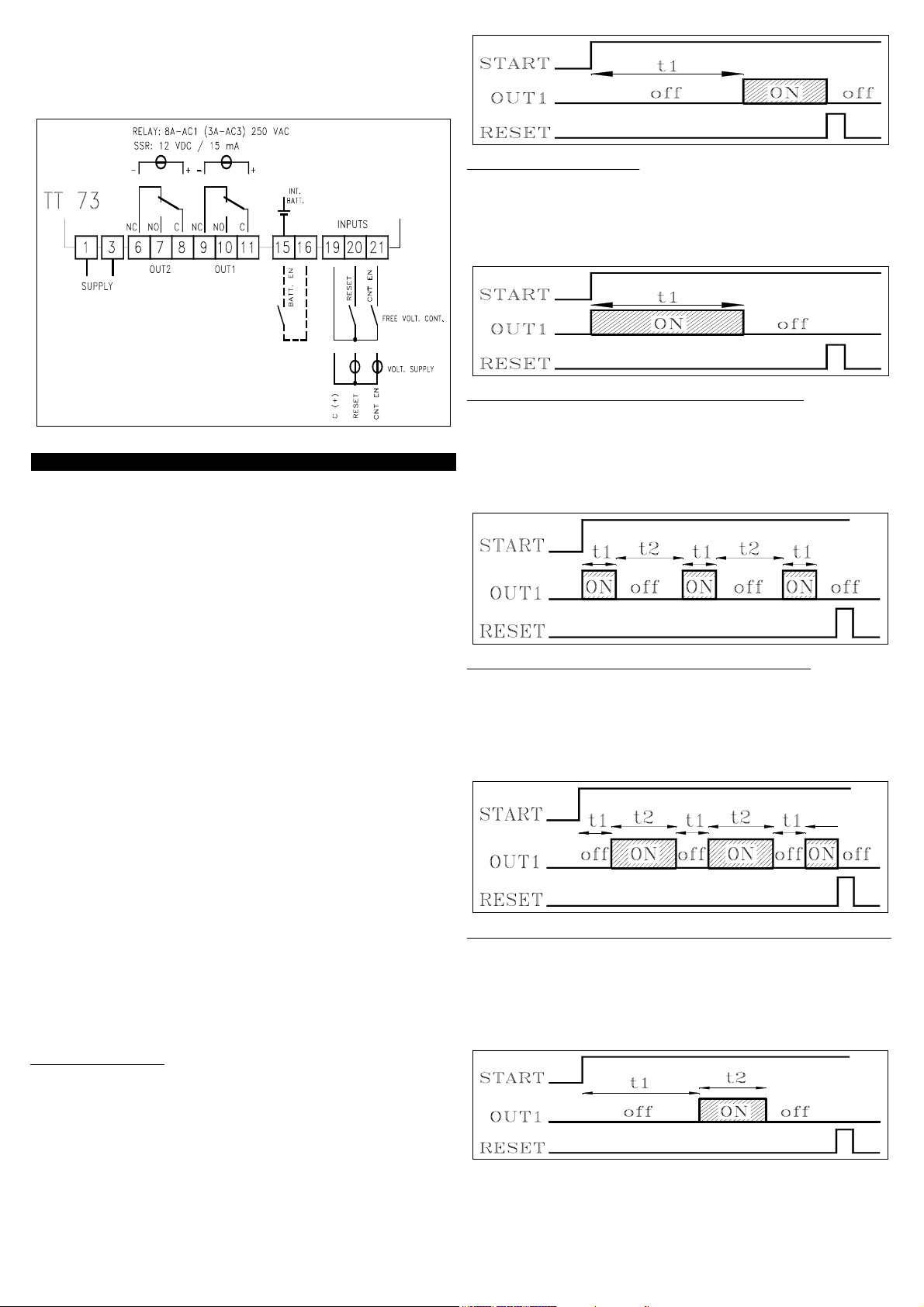
3.4 - ELECTRICAL CONNECTION DRAWING
4 - OPERATING MODE
4.1 – FUNCTIONING OF THE COUNTING COMMANDS
The counting can be enabled and disabled through the frontal key T,
or through the remote inputs CNT EN and RES.
The operating mode of the key T is defined by the parameter "t",
the operating mode of the input CNT EN is defined by the parameter
"E" while the input RES always works as reset, i.e. it stops and
resets the counting when it is activated and moreover it has priority
on the other commands (when it is activated it doesn't allow the
starting of the counting).
When the instrument is predisposed for the continuation of the
counting also without power supply, during the counting under
conditions of lack of supply the only active command is the RESET
one, which can be given only from the frontal key T.
When the instrument is supplied through the battery it is not
therefore possible to make the counting start again once stopped.
4.2 – FUNCTIONING OF THE DISPLAY
The led SET/CNT is used to indicate the access into the
programming (flashing fast), the counting in action (flashing each
second), the counting interrupted before the term (lighted fixed) or
the counting finished and the state of reset (off).
After the reset, the display visualizes 0000 if the counting mode is
programmed as UP (par. "C" = 1) or it visualizes the programmed
set value if the counting mode is programmed as DOWN (par. "C" =
2).
During the counting, the display visualizes the value of time that
spends in UP or in DOWN mode.
If the back-up mode has been programmed to continue the counting
in action without power supply, the display remains lighted but with
an inferior brightness (with the purpose to limit as much as possible
the absorption from the battery).
4.3 - OUT1 OPERATING MODE
The instrument can be programmed by the parameter "F1" to
operate in any of the following 5 modes:
F1 = 1 -
On receiving the START signal, the instrument starts counting time.
When the set time value “t1” has been reached, the instrument
enables the output OUT1.
The output is disabled by the RESET signal.
DELAYED :
F1 = 2 - FEEDTHROUGH :
On receiving the START signal, the instrument enables the output
OUT1.
The output is disabled when the set time value “t1” has been
reached.
The output will be enabled again after the transmission of a RESET
signal and a subsequent START signal.
F1 = 3 - ASYMMETRICAL OSCILLATOR START ON:
This operating mode allows the user to enter two SET times “t1” and
“t2”, and therefore also involves the "S2" parameter .
On receiving the START signal, the output OUT1 is immediately
enabled and remains enabled for the time period t1.
Then the output is disabled and remains disabled for the time period
t2.
This procedure goes on until a RESET signal is transmitted.
F1 = 4 - ASYMMETRICAL OSCILLATOR START OFF:
This operating mode allows the user to enter two SET times “t1” and
“t2”, and therefore also involves the "S2" parameter .
On receiving the START signal, the output remains disabled until
the set time period “t1” has expired.
Then the output is enabled.
The output is disabled again when the set time period “t2” has
expired. This procedure goes on until a RESET signal is transmitted.
F1 = 5 - ONE CYCLE ASYMMETRICAL OSCILLATOR START OFF:
The operation results similar to the "F1"=4 with the only difference
that only one cycle of OFF/ON is performed.
To the start signal the output OUT1 remains disabled for the time
“t1".
When the time “t1” is expire the output will be on for the time “t2”.
The cycle will be enabled again after the transmission of a RESET
signal and a subsequent START signal.
TECNOLOGIC spa - TT 73 - OPERATING INSTRUCTIONS - Vr. 01 - ISTR 06083 - PAG. 3
 Loading...