

Page 1

E
A
S
E
S
E
D
TLV 10
MICROPROCESSOR-BASED
DIGITAL ELECTRONIC
THERMOMETER
INDICE
2.2
3.1
3.3
6
6.3
7.2
7.3
7.5
INSTRUMENT DESCRIPTION1
GENERAL DESCRIPTION1.1
FRONT PANEL DESCRIPTION1.2
PROGRAMMING2
PARAMETERS PROGRAMMING2.1
PARAMETER PROTECTION USING THE PASSWOR
PARAMETERS PROGRAMMING LEVEL2.3
INFORMATION ON INSTALLATION AND USE 3
PERMITTED US
MECHANICAL MOUNTING3.2
ELECTRICAL CONNECTION
ELECTRICAL WIRING DIAGRAM3.4
FUNCTIONS4
MEASURING AND VISUALIZATION4.1
PARAMETERS CONFIGURATION BY KEY014.2
PROGRAMMABLE PARAMETERS TABLE5
PROBLEMS , MAINTENANCE AND GUARANTE
SIGNALLING6.1
CLEANING6.2
GUARANTEE AND REPAIR
TECHNICAL DATA7
ELECTRICAL DATA7.1
MECHANICAL DAT
MECHANICAL DIMENSIONS, PANEL CUT-OUT AND
MOUNTING
FUNCTIONAL DATA7.4
INSTRUMENT ORDERING COD
OPERATING INSTRUCTIONS
Vr. 01 (ENG) - 11/05 - cod.: ISTR 06939
TECNOLOGIC S.p.A.
VIA INDIPENDENZA 56
27029 VIGEVANO (PV) ITALY
TEL.: +39 0381 69871
FAX: +39 0381 698730
internet : http:\\www.tecnologic.it
e-mail: [email protected]
FOREWORD
This manual contains the information
necessary for the product to be installed
correctly and also instructions for its
maintenance and use; we therefore recommend
that the utmost attention is paid to the following
instructions and to save it.
This document is the exclusive property of TECNOLOGIC
S.p.A. which forbids any reproduction and divulgation , even
in part, of the document, unless expressly authorized.
TECNOLOGIC S.p.A. reserves the right to make any formal or
functional changes at any moment and without any notice.
Whenever a failure or a malfunction of the device may cause
dangerous situations for persons, thing or animals, please
remember that the plant has to be equipped with additional
devices which will guarantee safety.
Tecnologic S.p.A. and its legal representatives do not assume
any responsibility for any damage to people, things or animals
deriving from violation, wrong or improper use or in any case
not in compliance with the instrument’s features.
1 - INSTRUMENT DESCRIPTION
1.1 - GENERAL DESCRIPTION
TLV 10 is a digital microprocessor based thermometer. The
instrument has one input for PTC or NTC temperature probes that
can be configured. The instrument is equipped with 4 programme
keys and a 4-digit display. Other important characteristics of the
instrument are: programme parameters protection using
personalised password, configuration of parameters via the KEY 01
device and the possibility of power supply in the range 100 ... 240
VAC.
1.2 - FRONT PANEL DESCRIPTION
TLV 10
1 - Key P : Used for programming the function parameters
2 - Key DOWN : Used for decreasing the values to be set and for
selecting the parameters.
3 - Key UP : Used for increasing the value to be set and for
selecting the parameters.
4 - Key U : In the “hidden” parameter programming mode it’s used
to modify the visibility of the parameters (see par. 2.3).
5 - Led SET : Indicates the input in programming mode and the
programming level of the parameters.
2 - PROGRAMMING
2.1 - PARAMETERS PROGRAMMING
To access the instrument’s function parameters, press the key P
and keep it pressed for about 5 seconds, after which the SET led
will light up, the display will visualised the code that identifies the
first parameter.
Using the UP and DOWN keys, the desired parameter can be
selected and pressing the P key, the display will alternately show
the parameter code and its setting that can be changed with the UP
and DOWN keys.
4
3
2
1
5
TECNOLOGIC - TLV 10 - OPERATING INSTRUCTIONS - Vr.01 - 11/05 - ISTR 06939 - PAG. 1
Page 2
Once the desired value has been set, press the key P again: the
E
new value will be memorised and the display will show only the
code of the selected parameter.
Pressing the UP and DOWN keys, it is possible to select another
parameter and change it as described.
To exit the programming mode, do not press any key for about 20
seconds, or keep the UP or DOWN key pressed until it exits the
programming mode.
2.2 - PARAMETER PROTECTION USING THE PASSWORD
The instrument has a parameter protection function using a
password that can be personalised, through the “PASS”
parameter.
If one wishes to have this protection, set the password number
desired in the parameter “PASS”.
When the protection is working, press the P key to access the
parameters and keep it press for about 5 seconds, after which the
LED SET will flash and the display will show “0” .
At this point, using the UP and DOWN keys, set the password
number programmed and press the key "P".
If the password is correct, the display will visualise the code that
identifies the first parameter and it will be possible to programme
the instrument in the same ways described in the previous section.
Protection using a password can be disabled by setting the
parameter “PASS” = OFF.
2.3 - PARAMETERS PROGRAMMING LEVELS
The instrument has two parameter programming levels.
The first level (“visible” parameters) is accessed according to the
procedure described above (with or without password request)
while the second level (“hidden” password) can be accessed
according to the following procedure.
Remove the power supply to the instrument, press the key P and
return power to the instrument, keeping the key pressed.
After about 5 sec. the SET led will light up, the display will show the
code that identifies the first parameter and it will be possible to set
the parameters of the instrument using the same programming
procedure described previously.
Once the parameter has been selected and the SET is on, it means
that the parameter can be programmed even on the first level
("visible”).
If the LED is off it means that the parameter can only be
programmed on this level (i.e. “hidden”).
To change the visibility of the parameter, press the key U: the led
SET will change status, indicating the accessibility level of the
parameter (on = parameter “visible”; off = parameter “hidden”).
The access procedure for “hidden” parameters allows the “PASS”
parameter to be checked and changed, and is useful therefore if
the password set has been forgotten.
3 - INFORMATION ON INSTALLATION AND US
declared. Avoid placing the instrument in environments with very
high humidity levels or dirt that may create condensation or
introduction of conductive substances into the instrument. Ensure
adequate ventilation to the instrument and avoid installation in
containers that house devices which may overheat or which may
cause the instrument to function at a higher temperature than the
one permitted and declared. Connect the instrument as far away as
possible from sources of electromagnetic disturbances such as
motors, power relays, relays, solenoid valves, etc.
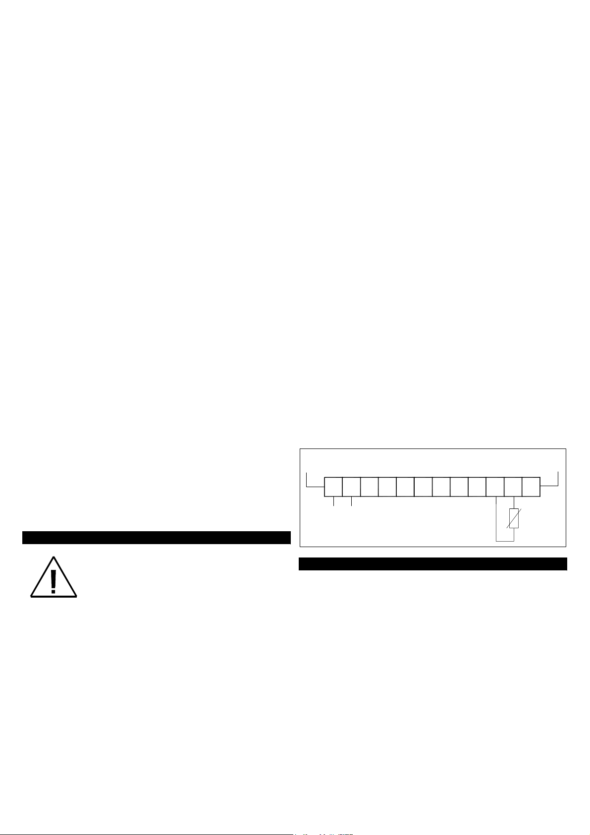
3.3 - ELECTRICAL CONNECTION
Carry out the electrical wiring by connecting only one wire to each
terminal, according to the following diagram, checking that the
power supply is the same as that indicated on the instrument and
that the load current absorption is no higher than the maximum
electricity current permitted. As the instrument is built-in equipment
with permanent connection inside housing, it is not equipped with
either switches or internal devices to protect against overload of
current: the installation will include an overload protection and a
two-phase circuit-breaker, placed as near as possible to the
instrument, and located in a position that can easily be reached by
the user and marked as instrument disconnecting device which
interrupts the power supply to the equipment. It is also
recommended that the supply of all the electrical circuits connected
to the instrument must be protect properly, using devices (ex.
fuses) proportionate to the circulating currents. It is strongly
recommended that cables with proper insulation, according to the
working voltages and temperatures, be used. Furthermore, the
input cable of the probe has to be kept separate from line voltage
wiring. If the input cable of the probe is screened, it has to be
connected to the ground with only one side. Whether the
instrument is 12 V version it’s recommended to use an external
transformer TCTR, or with equivalent features, and to use only one
transformer for each instrument because there is no insulation
between supply and input. We recommend that a check should be
made that the parameters are those desired and that the
application functions correctly before connecting the outputs to the
actuators so as to avoid malfunctioning that may cause
irregularities in the plant that could cause damage to people, things
or animals.
3.4 - ELECTRICAL WIRING DIAGRAM
TLV 10
SUPPLY
21
534 76
INPUT
1089 1211
PTC-NTC
PROBE
3.1 - PERMITTED USE
The instrument has been projected and
manufactured as a measuring and control device to
be used according to EN61010-1 for the altitudes
operation until 2000 ms. The use of the instrum ent
for applications not expressly permitted by the
above mentioned rule must adopt all the necessary protective
measures. The instrument CANNOT be used in dangerous
environments (flammable or explosive) without adequate
protection. The installer must ensure that EMC rules are respected,
also after the instrument installation, if necessary using proper
filters. Whenever a failure or a malfunction of the device may cause
dangerous situations for persons, thing or animals, please
remember that the plant has to be equipped with additional devices
which will guarantee safety.
3.2 - MECHANICAL MOUNTING
The instrument, in case 33 x 75 mm, is designed for flush-in panel
mounting. Make a hole 29 x 71 mm and insert the instrument, fixing
it with the provided special bracket. We recommend that the gasket
is mounted in order to obtain the front protection degree as
TECNOLOGIC - TLV 10 - OPERATING INSTRUCTIONS - Vr.01 - 11/05 - ISTR 06939 - PAG. 2
4 - FUNCTIONS
4.1 - MEASURING AND VISUALIZATION
Via the parameter “SEnS” it is possible to select the type of
probes that one wishes to use and which can be: thermistores PTC
KTY81-121 (Ptc) or NTC 103AT-2 (ntc).
Once the type of probe used has been selected, through the
parameter “Unit”, it is possible to select the temperature unit of
measurement (°C or °F) and, through the parameter “dP”, the
resolution of the desired measurement (OFF=1°; On =0,1°).
The instrument allows the measuring to be calibrated, that can be
used for re-calibrating the instrument according to application
needs, through the parameters “OFS”.
Using the parameter “FiL”, it is possible to set the time constant
for the software filter for measuring the input values to be able to
reduce the sensitivity to measurement disturbances (increasing the
time).
4.2 - PARAMETERS CONFIGURATION BY “KEY01”
The instrument is equipped with a connector that allows the
transfer from and toward the instrument of the functioning
Page 3

parameters through the device TECNOLOGIC KEY01 with 5 poles
E
r
r
connector.
This device it’s mainly useable for the serial programming of the
instruments which need to have the same parameters configuration
or to keep a copy of the programming of an instrument and allow its
rapid retransmission.
To use the device KEY01 it’s necessary that the device or
instrument are being supplied.
Instrument supplied and device not supplied
SUPPLY
Instrument supplied from the device
SUPPLY ADAPTER
12 VDC AC SUPPLY
For additional info, please have a look at the KEY01 instruction
manual.
5 - PROGRAMMABLE PARAMETERS TABLE
NoteDef.RangeDescriptionPar.
1
2
SEnS
Probe Calibration
OFS
ntcPtc - ntcProbe Type
0.0-30.0 ÷ 30.0
°C/°F
3
Unit
4
dP
5
Measurement filter
FiL
°C°C - °FUnit of measurement
OnOn - OFFDecimal point
2.0OFF ÷ 20.0
sec
6
PASS
OFFOFF ÷ 9999Access Password to
parameter functions
The eventual opening of the housing, the violation of the instrument
or the improper use and installation of the product will bring about
the immediate withdrawal of the warranty’s effects.
In the event of a faulty instrument, either within the period of
warranty, or further to its expiry, please contact our sales
department to obtain authorisation for sending the instrument to
our company.
The faulty product must be shipped to TECNOLOGIC with a
detailed description of the faults found, without any fees or charge
for Tecnologic, except in the event of alternative agreements.
7 - TECHNICAL DATA
7.1 - ELECTRICAL DATA
Power supply:
Frequency AC:
Power consumption:
Input/s:
12 VAC/VDC, 24 VAC/VDC, 100..240 VAC +/- 10%
50/60 Hz
3 VA approx.
1 input for temperature probes: PTC (KTY 81-121, 990 Ω
@ 25 °C) or NTC (103AT-2, 10KΩ @ 25 °C)
Installation category:
Measurement category:
Protection
Insulation:
class against electric shock: Class II for Front panel
Reinforced insulation between the low voltage part
II
I
(supply) and front panel; Reinforced insulation between the low
voltage section (supply) and the extra low voltage section (input);
No insulation between supply F type and input.
7.2 - MECHANICAL DATA
Housing:
Dimensions:
Weight:
Mounting:
Connections:
Degree of front panel protection :
Self-extinguishing plastic, UL 94 V0
33 x 75 mm, depth 64 mm
100 g approx.
Flush in panel in 29 x 71 mm hole
2,5 mm2 screw terminals block
IP 65 mounted in panel with
gasket
Pollution situation:
Operating temperature:
Operating humidity:
Storage temperature:
2
0 ... 50 °C
30 ... 95 RH% without condensation
-10 ... +60 °C
7.3 - MECHANICAL DIMENSIONS, PANEL CUT-OUT AND
MOUNTING [mm]
75
TLV 10
33
5
28
6 - PROBLEMS, MAINTENANCE AND GUARANTE
6.1 - SIGNALLING
Error Signalling:
Action ReasonErro
E1
-E1
EEP
The probe may be
interrupted or in short
circuit, or may measure
a value outside the
range allowed
Internal memory error
Check the correct
connection of the probe
with the instrument and
check the probe works
correctly
Check and if necessary
re-programme the
parameters function.
6.2 - CLEANING
We recommend cleaning of the instrument with a slightly wet cloth
using water and not abrasive cleaners or solvents which may
damage the instrument.
6.3 - GUARANTEE AND REPAIRS
The instrument is under warranty against manufacturing flaws or
faulty material, that are found within 12 months from delivery date.
The guarantee is limited to repairs or to the replacement of the
instrument.
TECNOLOGIC - TLV 10 - OPERATING INSTRUCTIONS - Vr.01 - 11/05 - ISTR 06939 - PAG. 3
min. 12 mm
64
min. 15 mm
71
29
RECOMMENDED
PANEL CUTOUT
Page 4

BRACKETS
TYPE 2
86
74
BRACKET
TYPE 1
TYPE 2
MAX 12 mm
PANEL + GASKET
7.4 - FUNCTIONAL FEATURES
Measurement range:
PTC: -50...150 °C / -58 ... 302 °F;
NTC: -50...109 °C / -58...228 °F
Display resolution:
Overall accuracy:
Sampling rate:
Display:
4 Digit Red h 12 mm
Compliance:
1 ° or 0,1°
+/- (0,5 % fs + 1 digit)
130 ms.
ECC directive EMC 89/336 (EN 61326), ECC directive
LV 73/23 and 93/68 (EN 61010-1)
TYPE 1
31
PANEL + GASKET
34
43
MAX 29 mm
7.5 - INSTRUMENT ORDERING CODE
TLV 10 a bb c
a : POWER SUPPLY
H = 100...240 VAC
L = 24 VAC/VDC
F = 12 VAC/VDC
bb
: SPECIAL CODES
c : SPECIAL VERSIONS
TECNOLOGIC - TLV 10 - OPERATING INSTRUCTIONS - Vr.01 - 11/05 - ISTR 06939 - PAG. 4
 Loading...