

Page 1
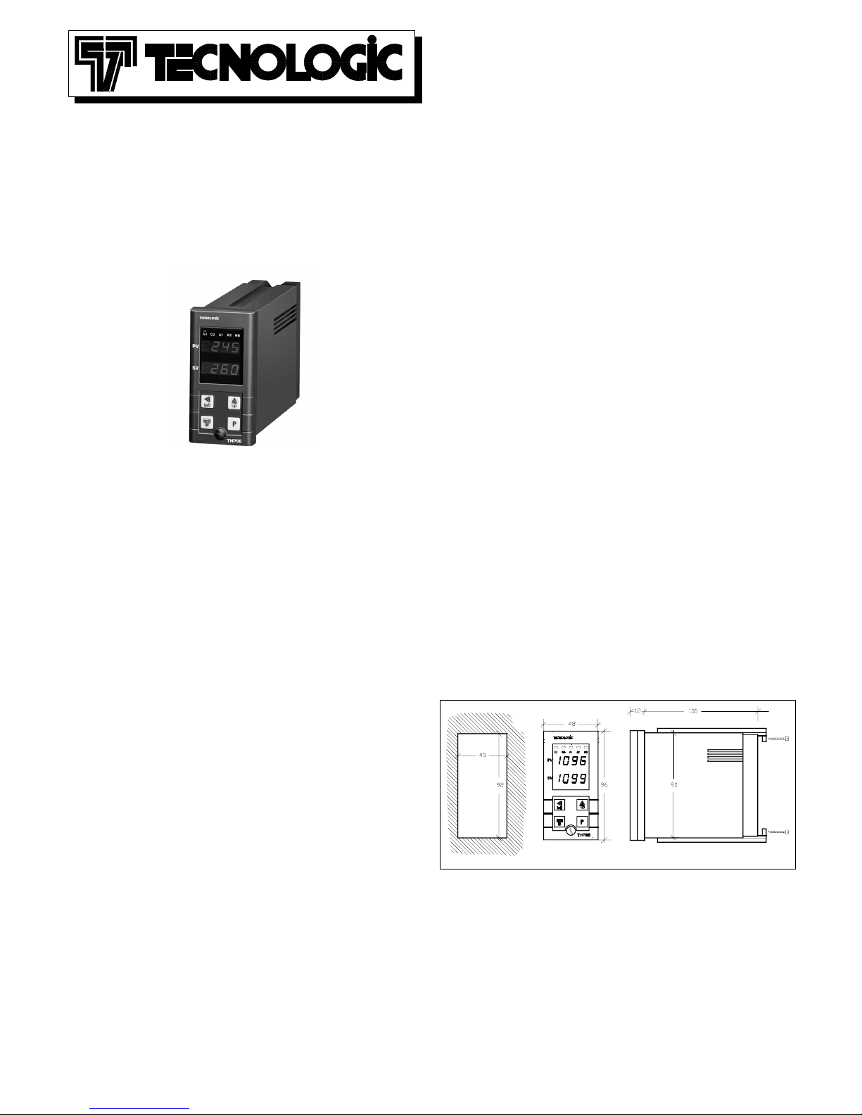
THP 98
TERMOREGOLATORE ELETTRONICO
DIGITALE A MICROPROCESSORE
MICROPROCESSOR-BASED DIGITAL
ELECTRONIC THERMOCONTROLLER
ISTRUZIONI PER L'USO
OPERATING INSTRUCTIONS
Vr. 01 (I - GB) - cod.: ISTR 00372
TECNOLOGIC S.p.A.
VIA INDIPENDENZA 56
27029 VIGEVANO (PV) ITALY
TEL.: ++39 0381 69871 - FAX: ++39 0381 698730
internet : http:\\www.tecnologic.it
e-mail: [email protected]
PREMESSA: Nel presente manuale sono contenute le informazioni
necessarie ad una corretta installazione e le istruzioni per l'utilizzo e la
manutenzione del prodotto, si raccomanda pertanto di leggere attentamente
le seguenti istruzioni. Ogni cura è stata posta nella realizzazione di questa
documentazione, tuttavia la TECNOLOGIC S.p.A. non può assumersi
alcuna responsabilità derivante dall'utilizzo della stessa. Lo stesso dicasi
per ogni persona o società coinvolta nella creazione del presente manuale.
La presente pubblicazione è di esclusiva proprietà della TECNOLOGIC
S.p.A. la quale pone il divieto assoluto di riproduzione e divulgazione,
anche parziale, se non espressamente autorizzata. La TECNOLOGIC S.p.A.
si riserva di apportare modifiche estetiche e funzionali in qualsiasi
momento e senza alcun preavviso.
PREVIOUS STATEMENT: In this manual are contained all the necessary
information for a correct installation and the instructions for the use and
the maintenance of the product; we recommend, therefore, to read
carefully the following instructions. The maximum care has been used in
the realisation of this document, anyway TECNOLOGIC S.p.A. does not
assume any responsibility deriving from the use of itself. The same
consideration has to be done for each person or Company involved in the
creation of this manual. The herewith issue is an exclusive property of
TECNOLOGIC S.p.A. which forbids any reproduction and divulgation,
although partial, if not expressly authorised. TECNOLOGIC S.p.A.
reserves the right to execute aesthetically and functional modifications, at
any moment and without any notice.
INDICE
PROBLEMI , MANUTENZIONE E GARANZIA7
TABELLA PARAMETRI6.1
DESCRIZIONE DEI PARAMETRI6
PROGRAMMAZIONE5
FUNZIONE ALLARME DI HEATER BREAK4.6
FUNZIONAMENTO DELLE USCITE DI ALLARME4.5
FUNZIONE DI AUTOTUNING4.4
REGOLATORE PID A DOPPIA AZIONE4.3
REGOLATORE PID A SINGOLA AZIONE4.2
REGOLATORE ON/OFF4.1
FUNZIONAMENTO4
INSTALLAZIONE3
DATI TECNICI2
CODIFICA DELLO STRUMENTO1.2
PANNELLO FRONTALE1.1
DESCRIZIONE GENERALE1
INDEX
TROUBLES, MAINTENANCE, GUARANTEE7
PARAMETERS TABLE6.1
DESCRIPTION OF PARAMETERS6
PROGRAMMING5
HEATER BREAK ALARM FUNCTION4.6
ALARM OUTPUTS OPERATING MODE4.5
AUTOTUNING FUNCTION4.4
DOUBLE ACTION PID CONTROL4.3
SIGLE ACTION PID CONTROL4.2
ON/OFF CONTROL4.1
OPERATING MODE4
INSTALLATION3
TECHNICAL DATA2
INSTRUMENT CODE1.2
FRONT PANEL1.1
GENERAL DESCRIPTION1
1 - DESCRIZIONE GENERALE
Il modello THP 98 è un termoregolatore digitale a microprocessore "single
loop", con regolazione ON/OFF, PID a singola azione, PID a doppia azione
(diretta e inversa) e con funzione di AUTOTUNING per la regolazione
PID. Il valore di processo viene visualizzato su 4 display rossi (PV) , il
valore di Set su 4 display verdi (SV), mentre lo stato delle uscite viene
segnalato da 5 led. Lo strumento prevede sino a 5 uscite : 1 o 2 uscite di
regolazione (C1, C2), 1 o 2 uscite di allarme (A1,A2) e 1 uscita di allarme
di Heater Break (HB) , tutte a relè o per il pilotaggio di relè statici (SSR)
L'ingresso accetta sonde di temperatura come Termocoppie (J, K, R, S, T) e
Termoresistenze (Pt100). Lo strumento può disporre inoltre di un ingresso
per trasformatore amperometrico per la funzione di Heater Break.
TECNOLOGIC - THP 98 USER MANUAL (I - GB) - Vr. 01 - ISTR 00372 - PAG. 1
Page 2
1.1
-
PANNELLO FRONTALE
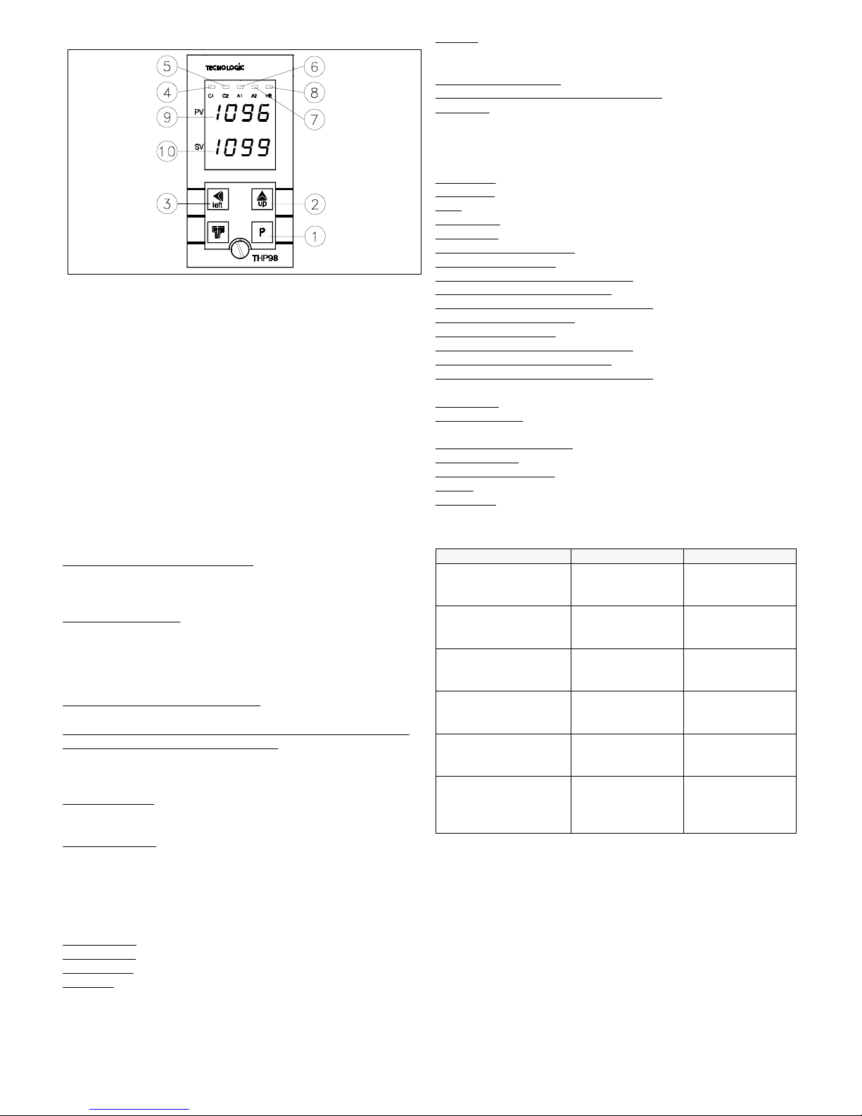
1 - Tasto P : Utilizzato per la programmazione dei parametri di
funzionamento. Viene usato quindi per confermare i dati impostati e
passare quindi al parametro successivo
2 - Tasto UP : Utilizzato per incrementare la cifra sulla quale si trova il
"cursore" (nel caso di parametri non numerici, il tasto "UP" serve per
selezionare le opzioni disponibili)
3 - Tasto LEFT : Utilizzato per spostare il "cursore" (cifra che lampeggia)
sulla cifra che si vuole modificare, per visualizzare la corrente misurata
dall’ingresso TAHB e per resettare la memoria allarme
4 - Led C1 : Indica lo stato dell'uscita C1 on (acceso) o off (spento)
5 - Led C2 : Indica lo stato dell'uscita C2 on (acceso) o off (spento)
6 - Led A1 : Indica lo stato dell'uscita A1 on (acceso) o off (spento)
7 - Led A2 : Indica lo stato dell'uscita A2 on (acceso) o off (spento)
8 - Led HB : Indica lo stato dell'uscita HB on (acceso) o off (spento)
9 - Display PV: Indica normalmente il valore di processo
10 - Display SV: Indica normalmente il valore di Set Point
1.2 - CODIFICA DELLO STRUMENTO
THP 98 T aa bb c d e ff
aa
= Funzione Allarme Heater Break
-- : Non presente
HR : Presente con uscita a Relè
HO : Presente con uscita in tensione 24 VDC per SSR
bb
= Uscite di Allarme
-- : Nessuna
1R : 1 Allarme con uscita a Relè (A1)
2R : 2 Allarmi con uscita a Relè (A1, A2)
1O : 1 Allarme con uscita in tensione 24 VDC per SSR (A1)
2O : 2 Allarmi con uscita in tensione 24 VDC per SSR (A1, A2)
c = Uscita di regolazione primaria (C1)
R : A Relè e 24 VDC per SSR
d = Uscita di regolazione secondaria (C2) per controllo
PID a doppia
azione (Raffreddamento e Riscaldamento)
- : Non presente
R : A Relè
O : In tensione 24 VDC per SSR
e = Alimentazione
L : 24 VAC/VDC
H : 90 ... 240 VAC
ff = Codici Special
N.B.: Tutte le uscite di allarme (A1, A2, HB) devono essere dello stesso
tipo (o tutte a Relè o tutte in tensione per pilotaggio SSR)
2 - DATI TECNICI
CARATTERISTICHE ELETTRICHE
Alimentazione:
24 VAC/VDC, 90... 240 VAC +/- 10%
Frequenza AC:
50/60 Hz
Assorbimento:
7 VA circa
Ingresso/i:
1 ingresso per sonde di temperatura (tc J,K,R,S,T; RTD Pt 100
IEC). 1 ingresso per trasformatore amperometrico con K=1/0,002 (Max.
200 mA)
Uscita/e:
Sino a 5 uscite. A relè (5A-AC1, 2 A-AC3 250 VAC), 10 A max
per comune (pin 12); o in tensione per pilotaggio SSR (24VDC/0mA,
14VDC/20mA)
Vita elettrica uscite a relè:
100000 operaz.
Classe di protezione contro le scosse elettriche:
Frontale in Classe II
Isolamenti:
Rinforzato tra parti in bassa tensione (alimentazione e uscite a
relè) e frontale; Principale tra parti in bassa tensione (alimentazione e uscite
a relè) e parti in bassissima tensione (ingressi e uscite statiche); Nessun
isolamento tra ingressi e uscite statiche
CARATTERISTICHE MECCANICHE
Contenitore:
Plastico autoestinguente UL 94 V0
Dimensioni:
48 x 96 mm DIN, prof. 100 mm
Peso:
290 g circa
Installazione:
Incasso a pannello in foro 45 x 92 mm
Connessioni:
Faston 6.3 mm
Grado di protezione frontale:
IP 54 con guarnizione
Situazione di polluzione:
Normale
Temperatura ambiente di funzionamento:
0 ... 55 °C
Umidità ambiente di funzionamento:
30 ... 95 RH% senza condensazione
Temperatura di trasporto e
immagazzinaggio: -10 ... +60 °C
Grado di protezione frontale:
IP 54 con guarnizione
Situazione di polluzione:
Normale
Temperatura ambiente di funzionamento:
0 ... 55 °C
Umidità ambiente di funzionamento:
30 ... 95 RH% senza condensazione
Temperatura di trasporto e
immagazzinaggio: -10 ... +60 °C
CARATTERISTICHE FUNZIONALI
Regolazione:
ON/OFF, PID
Range
di misura: Secondo la sonda utilizzata e l'unità di misura (vedi
tabella)
Risoluzione visualizzazione:
Secondo la sonda utilizzata. 1/0,1
Precisione totale:
+/- 0,25 % fs
Velocità di acquisizione:
1 acquisizione al secondo
Azione:
tipo 1C secondo EN 60730-1
Conformita':
Direttiva CEE EMC 89/336 (EN 50081-1, EN 50082-1),
Direttiva CEE BT 73/23 e 93/68 (EN 60730-1)
TABELLA RANGE DI MISURA
Pt2
-99.9 ... 850.0 °C
-99.9 ... 999.9 °F
73.0 ... 999.9 K
Pt1
-200 ... 850 °C
-328 ... 1562 °F
73 ... 1123 K
RTD Pt100 IEC
(Pt1, Pt2)
- - - -200 ... 400 °C
-328 ... 752 °F
73 ... 673 K
tc T
(t)
- - - -50 ... 1760 °C
-58 ... 3200 °F
223 ... 2033 K
tc S
(S)
- - - 0 ... 1760 °C
32 ... 3200 °F
273 ... 2033 K
tc R
(r)
- - - -200 ... 1370 °C
-328 ... 2498 °F
73 ... 1643 K
tc K
(CrAl)
- - - -200 ... 870 °C
-328 ... 1598 °F
73 ... 1143 K
tc J
(J)
4 DIGIT with D.P.4 DIGIT PROBE
3 - INSTALLAZIONE
MONTAGGIO MECCANICO: Lo strumento, in contenitore DIN 48 x
96 mm, è concepito per il montaggio ad incasso a pannello. Praticare
quindi un foro 45 x 92 mm ed inserirvi lo strumento fissandolo con le
apposite staffe fornite. Si raccomanda di montare l'apposita guarnizione per
ottenere il grado di protezione frontale IP54. Evitare di collocare la parte
interna dello strumento in luoghi soggetti ad alta umidità o sporcizia.
Installare lo strumento il più lontano possibile da fonti che possono
generare disturbi elettromagnetici e quindi anche da motori, teleruttori, relè,
elettrovalvole ecc. Lo strumento inoltre è estraibile frontalmente dal
proprio contenitore, quando si attua questa operazione si raccomanda di
disconnettere dall'alimentazione tutti i morsetti.
TECNOLOGIC - THP 98 USER MANUAL (I - GB) - Vr. 01 - ISTR 00372 - PAG. 2
Page 3
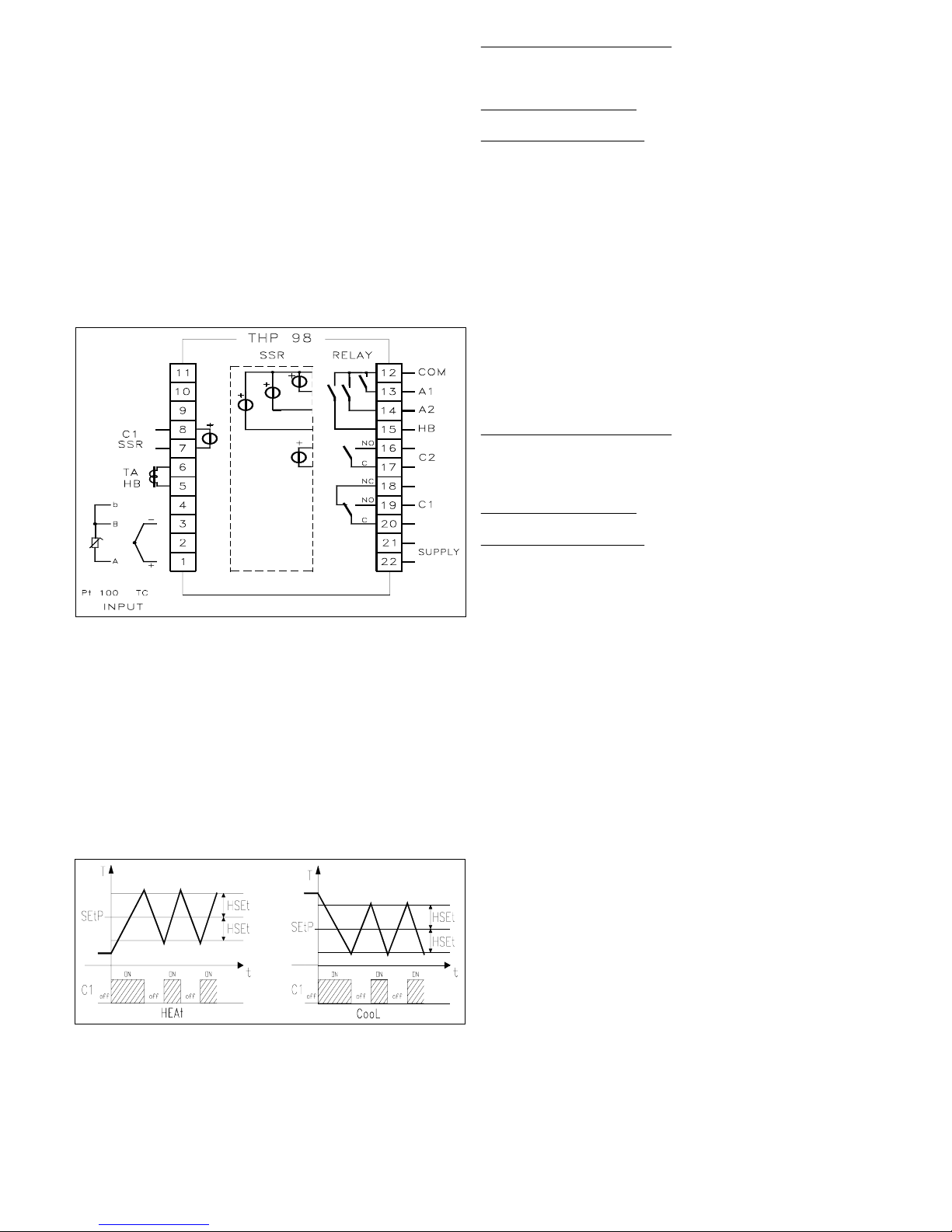
COLLEGAMENTI ELETTRICI: Effettuare le connessioni collegando
un solo conduttore per morsetto e seguendo lo schema riportato,
controllando che la tensione di alimentazione sia quella indicata sullo
strumento e che l'assorbimento degli attuatori collegati allo strumento non
sia superiore alla corrente massima consentita. Lo strumento, essendo
previsto per collegamento permanente entro un'apparecchiatura, non è
dotato di dispositivi interni di protezione da sovracorrenti, si raccomanda
pertanto di proteggere adeguatamente tutti i circuiti connessi allo strumento
con dispositivi (es. fusibili) adeguati alle correnti circolanti. Si raccomanda
di utilizzare cavi con isolamento appropriato alle tensioni e alle temperature
di esercizio e di fare in modo che il cavo di ingresso della sonda sia tenuto
distante dai cavi di alimentazione e da altri cavi di potenza. Se il cavo di
ingresso della sonda è schermato è preferibile collegarlo a terra da un solo
lato. Si consiglia di controllare che i parametri impostati siano quelli
desiderati prima di collegare le uscite agli attuatori onde evitare anomalie o
danneggiamenti dell'impianto controllato. Qualora un guasto
dell'apparecchio possa creare situazioni pericolose o dannose si ricorda che
l'impianto deve essere predisposto con dispositivi elettromeccanici
aggiuntivi per garantire la sicurezza.
4 - FUNZIONAMENTO
4.1 - REGOLATORE ON/OFF (C1)
Il modo di regolazione dello strumento di tipo ON/OFF è attuabile
impostando il parametro "Con1" = "OnOF" ed agisce sull'uscita C1 in
funzione del Set point impostato ("SEtP"), del modo di funzionamento
("FunC") e dell'isteresi ("HSEt") programmati. Lo strumento attua una
regolazione ON/OFF con isteresi simmetrica. Il regolatore si comporta
quindi nel seguente modo: in caso di azione inversa, o di riscaldamento
("HEAt"), disattiva l'uscita C1 quando la temperatura raggiunge il valore
[SEtP + HSEt] per riattivarla quando scende sotto al valore [SEtP - HSEt];
viceversa in caso di azione diretta o di raffreddamento ("CooL"), disattiva
l'uscita C1 quando la temperatura raggiunge il valore [SEtP - HSEt] per
riattivarla quando sale al di sopra del valore [SEtP + HSEt].
4.2 - REGOLATORE PID A SINGOLA AZIONE (C1)
Il modo di regolazione di tipo PID a singola azione è attuabile impostando
il parametro "Con1" = "Pid", ed agisce sull'uscita C1 in funzione del Set
point impostato ("SEtP"), del modo di funzionamento ("FunC")
programmato, e dell'algoritmo di controllo dello strumento che prevede
l'impostazione dei seguenti parametri:
Per il termine PROPORZIONALE:
"Pb" - Banda Proporzionale
"rS" - Reset manuale
"tcr1" - Tempo di ciclo dell'uscita C1.
Per il termine INTEGRALE:
"Int" - Tempo Integrale
Per il termine DERIVATIVO:
"dEr" - Tempo derivativo
4.3 - REGOLATORE PID A DOPPIA AZIONE (C1,C2)
La regolazione PID a doppia azione può avvenire solo quando lo strumento
è dotato di entrambe le uscite di regolazione (C1 e C2). In questo caso non
comparirà il parametro "Con1" poichè il modo di regolazione possibile è
solo di tipo PID a doppia azione. Questo tipo di regolazione viene
utilizzato per il controllo degli impianti che possiedono un elemento che
causa un incremento positivo (ad es. Riscaldante) e un elemento che causa
un incremento Negativo (ad es. Raffreddante). Il parametro "Func"
stabilisce il funzionamento dell'uscita C1, mentre l'uscita C2
automaticamente funzionerà in modo opposto. Ad esempio se "Func" =
"HEAt" all'uscita C1 andrà collegato l'elemento che causa incremento
positivo (ad es. Riscaldante) mentre all'uscita C2 andrà collegato l'elemento
che causa incremento negativo (ad es. Raffreddante). Il modo di
regolazione di tipo PID a doppia azione agisce quindi sulle uscite C1 e C2
in funzione del Set point impostato ("SEtP"), e dell'algoritmo di controllo
dello strumento che prevede l'impostazione dei seguenti parametri:
Per il termine PROPORZIONALE:
"Pb" - Banda Proporzionale
"rS" - Reset manuale
"tcr1" - Tempo di ciclo dell'uscita C1.
"tcr2" - Tempo di ciclo dell'uscita C2.
Per il termine INTEGRALE:
"Int" - Tempo Integrale
Per il termine DERIVATIVO:
"dEr" - Tempo derivativo
Oltre al parametro "Prat" (Power Ratio), nel quale è necessario impostare
il rapporto tra la potenza dell'elemento comandato dall'uscita C2 e potenza
dell'elemento comandato dall'uscita C1. Qualora il parametro "Prat" fosse
impostato = 0 , l'uscita C2 viene disabilitata e il regolatore si comporterà
esattamente come un regolatore PID a singola azione attraverso l'uscita C1.
4.4 - FUNZIONE DI AUTOTUNING
Lo strumento è impostato in fabbrica con i parametri relativi alla
regolazione PID su valori standard. Qualora questi non dovessero risultare
ottimali per la regolazione si consiglia di attivare la funzione di
AUTOTUNING che permette la sintonizzazione dello strumento per la
regolazione PID, sia a singola azione che a doppia azione, in maniera
automatica. Per attuare la funzione di AUTOTUNIG procedere come segue:
1) Impostare il Set point desiderato.
2) Impostare, se presente, il parametro "Con1" come "Pid".
3) Impostare il parametro "Func" in funzione del processo da controllare
attraverso l'uscita C1.
4) Collegare lo strumento all'impianto comandato.
5) Impostare il parametro "Auto" come:
- "SP" se si desidera effettuare l'autotuning sul valore di Set Point
programmato, oppure:
- "LoSP" se si desidera effettuare l'autotuning su un valore inferiore (pari
al 70 % del Set Point impostato).
6) Uscire dalla programmazione parametri.
A questo punto la funzione di Autotuning è attivata e viene segnalata
attraverso il lampeggiamento dei due punti decimali esterni del display
inferiore (SV). Il regolatore attua quindi una serie di operazioni
sull'impianto collegato al fine di calcolare i parametri della regolazione PID
più idonei. Attendere il termine del processo di Autotuning segnalato dal
ritorno del display al funzionamento normale per poter spegnere lo
strumento. Durante l'esecuzione dell'autotuning, vengono fatti eseguire
alcuni cicli di regolazione ON-OFF, che portano la temperatura ad oscillare
anche abbondantemente intorno al valore di set point (la maggiore o minore
oscillazione della temperatura è dovuta alla natura del processo da regolare
e non allo strumento). Se il processo non consente grosse variazioni di
temperatura al di sopra del valore di set impostato, si consiglia di
selezionare il ciclo di autotuning come "LoSP". La durata del processo di
TECNOLOGIC - THP 98 USER MANUAL (I - GB) - Vr. 01 - ISTR 00372 - PAG. 3
Page 4
Autotuning è limitata ad un massimo di 4 ore. Nel caso in cui il processo
non sia terminato nell'arco di 4 ore lo strumento visualizzerà "tout Auto"
lampeggiante. Nel caso invece si dovesse verificare un'anomalia durante
l'autotuning lo strumento visualizzerà "no Auto" lampeggiante. Per
interrompere il ciclo di Autotuning o ripristinare il funzionamento normale
dopo un errore spegnere e riaccendere lo strumento. I valori calcolati
saranno memorizzati automaticamente dallo strumento al termine
dell'esecuzione del ciclo di Autotuning nei parametri relativi alla
regolazione PID.
4.5 - FUNZIONAMENTO DELLE USCITE DI ALLARME (A1, A2)
Per la configurazione di funzionamento degli allarmi il cui intervento è
legato al valore di processo (A1, A2) è necessario impostare al parametro
"rL1" ("rL2") un codice costituito da 4 cifre così strutturato: a b c d dove:
a : Tipo di Allarme
b : Memoria Allarme
c : Comportamento all'accensione
d : Logica di attivazione dell'uscita
a - TIPO DI ALLARME
Si possono avere 6 differenti comportamenti dell'uscita di allarme, a
seconda del valore che assume la prima cifra del codice.
Note : Di seguito indicheremo negli esempi genericamente "ALn" per
intendere uno qualsiasi degli allarmi (AL1 o AL2). Inoltre quando viene
programmato l'allarme del tipo a finestra al posto dei parametri "ALn"
compariranno due parametri "ALnL" (Soglia inferiore) e "ALnH" (Soglia
superiore).
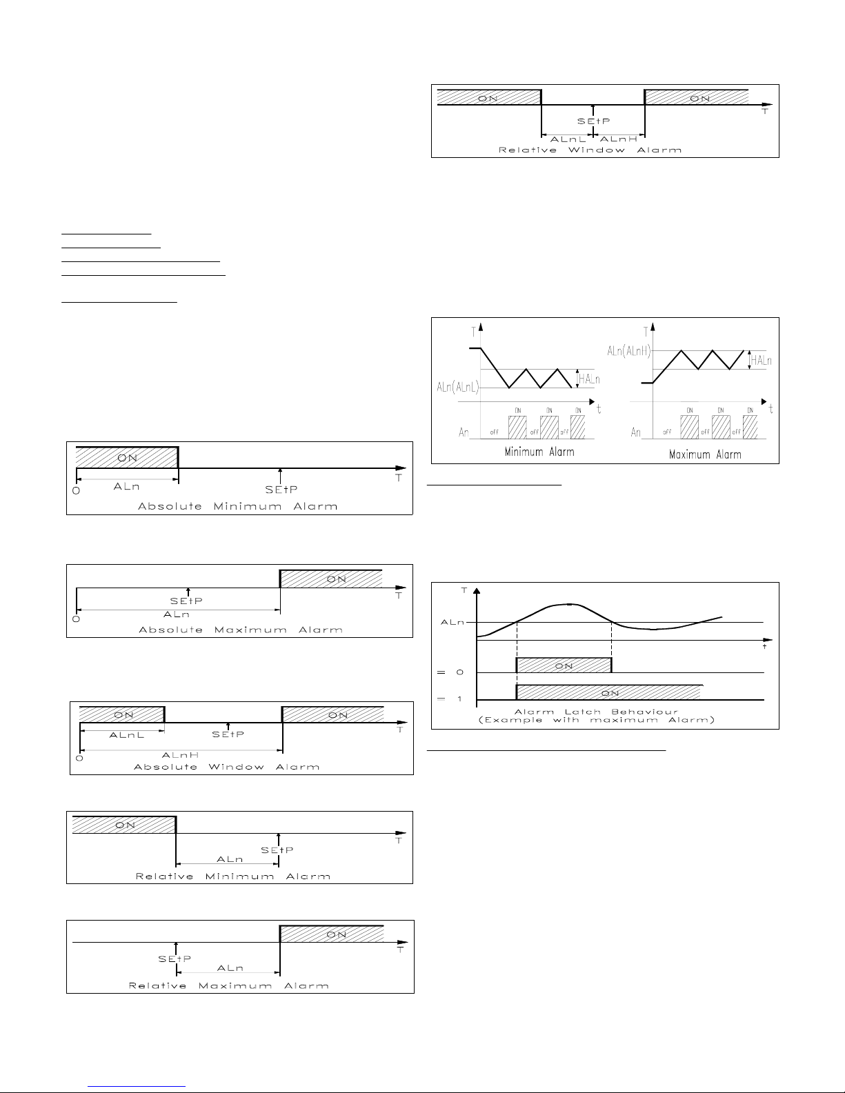
0 = ALLARME ASSOLUTO DI MINIMA: L'allarme viene attivato quando
il valore di processo scende al di sotto della soglia di allarme impostata al
parametro "ALn"
1 = ALLARME ASSOLUTO DI MASSIMA: L'allarme viene attivato
quando il valore di processo sale al di sopra della soglia di allarme
impostata al parametro "ALn"
2 = ALLARME ASSOLUTO A FINESTRA: L'allarme viene attivato
quando il valore di processo scende al di sotto della soglia di allarme
impostata al parametro "ALnL" oppure sale al di sopra della soglia di
allarme impostata al parametro "ALnH"
3 = ALLARME RELATIVO DI MINIMA: L'allarme viene attivato quando
il valore di processo scende al di sotto del valore [SEtP - ALn]
4 = ALLARME RELATIVO DI MASSIMA: L'allarme viene attivato
quando il valore di processo sale al di sopra del valore [SEtP + ALn]
5 = ALLARME RELATIVO A FINESTRA: L'allarme viene attivato
quando il valore di processo scende al di sotto del valore [SEtP - ALnL]
oppure quando il valore di processo sale al di sopra del valore [SEtP +
ALnH]
ISTERESI DEGLI ALLARMI: Il funzionamento degli allarmi è inoltre
influenzato dall'isteresi degli allarmi (par. "HALn"), che opera in modo
asimmetrico. Precisamente, in caso di allarme di minima, l'allarme si
attiverà quando il valore di processo scende al di sotto del valore della
soglia di allarme per disattivarsi quando sale al di sopra della soglia di
allarme + "HALn" ; nel caso di allarme di massima, l'allarme si attiverà
quando il valore di processo sale al di sopra della soglia di allarme per
disattivarsi quando scende al di sotto della soglia di allarme - "HALn". Per
gli allarmi a finestra l'esempio dell'allarme di minima si applica alla soglia
inferiore ("ALnL") mentre l'esempio dell'allarme di massima si applica alla
soglia superiore ("ALnH")
b - MEMORIA ALLARME: Si possono avere 2 differenti comportamenti
dell'uscita di allarme, a seconda del valore che assume la seconda cifra del
codice.
0 = ALLARME NON MEMORIZZATO: L'allarme rimane attivo solo nelle
condizioni di allarme
1 = ALLARME MEMORIZZATO: L'allarme si attiva quando vi sono le
condizioni di allarme e rimane attivo anche se tali condizioni non
permangono sino a quando non viene premuto il pulsante "LEFT".
c - COMPORTAMENTO ALL'ACCENSIONE: Si possono avere 2
differenti comportamenti dell'uscita di allarme, a seconda del valore che
assume la terza cifra del codice.
0 = COMPORTAMENTO NORMALE: L'allarme viene attivato sempre
quando vi sono le condizioni di allarme.
1 = ALLARME NON ATTIVO ALL'AVVIAMENTO: Se all'avviamento lo
strumento si trova nelle condizioni di allarme questo non viene attivato.
L'allarme si attiverà solo quando il valore di processo, dopo l'accensione,
non si è portato nelle condizioni di non allarme e successivamente nelle
condizioni di allarme.
TECNOLOGIC - THP 98 USER MANUAL (I - GB) - Vr. 01 - ISTR 00372 - PAG. 4
Page 5
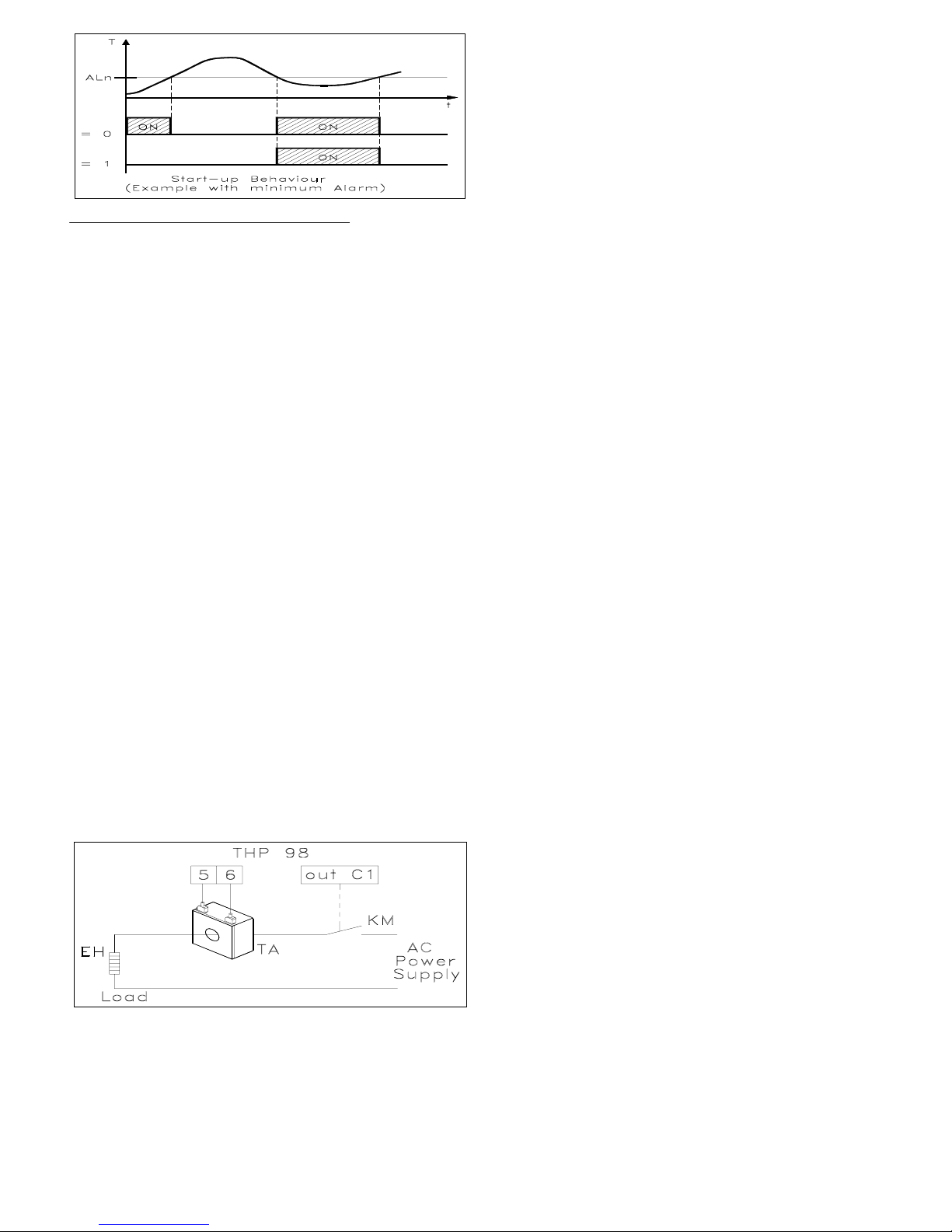
d - LOGICA DI ATTIVAZIONE DELL'USCITA: Si possono avere 2
differenti comportamenti dell'uscita di allarme, a seconda del valore che
assume la quarta cifra del codice.
1 = USCITA ATTIVATA IN CONDIZIONE DI ALLARME: L'uscita
viene attivata quando l'allarme è attivo, mentre è disattivata quando
l'allarme non è attivo.
0 = USCITA DISATTIVATA IN CONDIZIONI DI ALLARME: L'uscita
viene attivata quando l'allarme non è attivo, mentre è disattivata quando
l'allarme è attivo.
4.6 - FUNZIONE ALLARME DI HEATER BREAK (HB)
Lo strumento può essere dotato della funzione di allarme Heater Break
(Allarme rottura dell'elemento riscaldante), in questo caso esso disporrà di
un ingresso (TAHB) per la misura della corrente del carico comandato
dall'uscita C1. Tale ingresso accetta segnali provenienti da trasformatori
amperometrici (TA) sino ad un massimo di 200 mA (a 200 mA lo
strumento rileva il valore di 100.0). Pertanto per avere la corretta misura in
Ampere occorrerà che il rapporto del TA sia 1/0,002. La Tecnologic può
fornire i 2 modelli standard: TR03536: 25 A / 0,05 A e TR03537 : 100 A /
0,2 A. Durante il funzionamento è possibile visualizzare sul display SV la
corrente misurata dall'ingresso TAHB espressa in Ampere (se naturalmente
il rapporto del TA è 1/0,002) premendo il tasto "LEFT". L'allarme sarà
attivo quando, in condizioni di uscita C1 attiva, la corrente misurata
dall'ingresso TAHB risulterà inferiore al valore impostato al parametro
"ALHb". Al parametro "ALHb" andrà quindi impostato il valore della
corrente normalmente assorbita dal carico comandato dall'uscita C1
tenendo conto anche delle fluttuazioni della tensione di rete per evitare
allarmi indesiderati. Per quanto riguarda l'isteresi dell'allarme HB essa
viene calcolata automaticamente dallo strumento come il 2 % di "ALHb" ed
il comportamento è analogo ad un allarme di minima. Se si desidera
disattivare l'allarme HB è sufficiente impostare a 0.0 il parametro "ALHb".
Si possono avere 2 differenti comportamenti dell'uscita di allarme HB, a
seconda dell'impostazione del parametro "rLHb"
"nO" = COMPORTAMENTO "NORMALMENTE APERTO": L'uscita
viene attivata quando l'allarme è attivo, mentre è disattivata quando
l'allarme non è attivo.
"nC" = COMPORTAMENTO "NORMALMENTE CHIUSO": L'uscita
viene attivata quando l'allarme non è attivo, mentre è disattivata quando
l'allarme è attivo.
Note : La misura della corrente attraverso l'ingresso TAHB necessita di
almeno 100 mS.
5 - PROGRAMMAZIONE
Premere il tasto "P" e mantenerlo premuto per circa 2 secondi, lo strumento
mostrerà sul display superiore PV il codice del primo parametro ("SEtP") e
sul display inferiore SV il valore impostato con una cifra lampeggiante.
Questo sta ad indicare che è possibile modificarla agendo sul tasto "UP".
Qualora si intenda modificare una cifra diversa invece occorre selezionarla
mediante il tasto "LEFT" e quindi modificarla mediante il tasto "UP". Una
volta impostato il valore desiderato premere il tasto "P" e i display
mostreranno il codice e l'impostazione del parametro successivo. Agendo
sui tasti "LEFT" e "UP" è quindi possibile modificarlo come descritto. Una
volta impostati i valori desiderati premere il tasto "P" più volte sino a
quando lo strumento non esce dalla programmazione riportandosi nelle
condizioni normali di funzionamento visualizzando il valore di processo sul
display PV ed il valore di Set Point sul display SV. Diversamente lo
strumento esce automaticamente dal modo di programmazione dopo circa
50 secondi dal momento in cui si è premuto per l'ultima volta un tasto.
Come ultimo parametro nel primo livello viene visualizzato sul display PV
"PASS", questa è la richiesta della PASSWORD per accedere ai parametri
di secondo livello. Per avere accesso ai parametri di secondo livello dello
strumento occorre impostare, alla richiesta della Password, il numero
riportato nell'ultima pagina del presente manuale e quindi premere il tasto
"P". Se si imposta la Password errata lo strumento esce dalla
programmazione. Le modalità di impostazione dei parametri di secondo
livello sono le stesse descritte per i parametri di primo livello così come le
modalità di uscita dalla sessione di programmazione.
N.B. : Durante la programmazione dello strumento la regolazione viene
disattivata e le uscite di allarme vengono mantenute nello stato in cui si
trovavano prima dell'ingresso in programmazione. Uscire sempre
regolarmente dalla fase di programmazione poichè se lo strumento viene
spento durante la programmazione, alla successiva accensione verrà
segnalato un errore di memoria mediante la visualizzazione del messaggio
"Err EEPr". Per ripristinare il funzionamento occorre quindi premere
contemporaneamente i tasti "P" e "LEFT" e quindi entrare nella
programmazione dei parametri di primo livello e uscirne regolarmente,
anche senza variare i parametri. Nella programmazione dei parametri può
accadere che alcuni parametri descritti non vengono visualizzati, questo
avviene perchè lo strumento è predisposto per non visualizzare
automaticamente i parametri non necessari.
6 - DESCRIZIONE DEI PARAMETRI
Di seguito vengono descritti tutti i parametri di cui lo strumento può essere
dotato, si fa presente che alcuni di essi potranno non essere presenti o
perchè dipendono dal tipo di strumento utilizzato o perchè sono
automaticamente disabilitati in quanto parametri non necessari.
PARAMETRI DI PRIMO LIVELLO
SEtP - SET POINT : Valore di Set Point di regolazione
HSEt - ISTERESI SUL SET POINT: Semibanda simmetrica relativa al Set
Point che stabilisce i valori di attivazione e disattivazione dell'uscita di
regolazione C1 per il funzionamento con regolazione ON/OFF. Tale
parametro è visibile solo se la regolazione impostata è del tipo ON/OFF
("Con1" = "OnOF").
PASS - RICHIESTA DELLA PASSWORD: Utilizzato per immetere la
password che consente di accedere ai parametri di secondo livello
PARAMETRI DI PRIMO O SECONDO LIVELLO
I seguenti parametri sono normalmente visibili nel primo livello ma
possono essere spostati nel secondo livello mediante il parametro "ALPr" =
"yES".
AL1 - SOGLIA ALLARME A1 : Soglia di intervento dell'allarme A1 per
allarmi di minima o di massima.
AL1L - SOGLIA ALLARME A1 DI MINIMA PER ALLARME A
FINESTRA : Soglia di intervento dell'allarme A1 come allarme di minima
quando è impostato un allarme di tipo a finestra.
AL1H - SOGLIA ALLARME A1 DI MASSIMA PER ALLARME A
FINESTRA : Soglia di intervento dell'allarme A1 come allarme di massima
quando è impostato un allarme di tipo a finestra.
HAL1 - ISTERESI SULL'ALLARME A1: Semibanda asimmetrica relativa
al valore di impostazione dell'allarme A1 che stabilisce il valore di
disattivazione dell' allarme A1.
AL2 - SOGLIA ALLARME A2 : Analogo a "AL1" ma riferito ad A2.
AL2L - SOGLIA ALLARME A1 DI MINIMA PER ALLARME A
FINESTRA : Analogo a "AL1L" ma riferito ad A2.
AL2H - SOGLIA ALLARME A1 DI MASSIMA PER ALLARME A
FINESTRA : Analogo a "AL1H" ma riferito ad A2.
HAL2 - ISTERESI SULL'ALLARME A2: Analogo a "HAL1" ma riferito
all'allarme A2.
ALHb - SOGLIA ALLARME DI HEATER BREAK : Soglia di intervento
dell'allarme di Heater Break.
PARAMETRI DI SECONDO LIVELLO
TECNOLOGIC - THP 98 USER MANUAL (I - GB) - Vr. 01 - ISTR 00372 - PAG. 5
Page 6

rL1 - CONFIGURAZIONE DI FUNZIONAMENTO ALLARME A1 :
Permette di stabilire il funzionamento dell'allarme A1 attraverso
l'impostazione di un codice composto di 4 cifre (vedi funzionamento delle
uscite di allarme).
rL2 - CONFIGURAZIONE DI FUNZIONAMENTO ALLARME A2 :
Analogo a "rL1" ma riferito all'allarme A2.
rLHb - LOGICA DI FUNZIONAMENTO ALLARME HB : Permette di
stabilire la logica di funzionamento dell'uscita di allarme Heater Break HB
impostando lo stato a riposo dell'uscita "nO" = normalmente aperta , "nC"
= normalmente chiusa).
FAIL - ALLARME CHE SI DEVE ATTIVARE IN CASO DI ERRORE :
Consente di stabilire che in condizioni di errore dello strumento non venga
attivato nessun allarme ("no"), venga attivato l'allarme A1 ("rL1"), l'allarme
A2 ("rL2") o entrambi ("rL12").
dAL1 - DISABILITAZIONE ALLARME A1 : Consente di disabilitare
l'uscita di allarme A1 ("yES"). Disabilitando l'uscita, in condizioni di
allarme il led relativo all'allarme lampeggierà e l'uscita non verrà attivata.
Diversamente ("no") l'uscita funzionerà normalmente.
dAL2 - DISABILITAZIONE ALLARME A2 : Analogo a "dAL1" ma
riferito all'allarme A2.
ALPr - ALLARMI PROGRAMMABILI AL PRIMO O AL SECONDO
LIVELLO PARAMETRI : Permette di rendere visibili i parametri relativi
all'impostazione degli allarmi al primo ("no") o al secondo livello ("yES").
SPLL - SET POINT MINIMO: Valore minimo impostabile come Set Point
o limite inferiore del Set Point.
SPHL - SET POINT MASSIMO : Valore massimo impostabile come Set
Point o limite superiore del Set Point.
Con1 - TIPO DI REGOLAZIONE: Permette di selezionare uno dei
possibili modi di regolazione che lo strumento offre: ON/OFF ("OnOF") o
PID ("Pid"). Tale parametro non è visibile negli strumenti con 2 uscite di
regolazione (C1 e C2) poichè in questi la regolazione è solo PID per
entrambe le uscite.
Func - MODO DI FUNZIONAMENTO USCITA C1: Stabilisce se l'uscita
di regolazione C1 deve controllare un processo di Riscaldamento ("HEAt")
oppure un processo di Raffreddamento ("CooL"). Negli strumenti con 2
uscite di regolazione (C1 e C2) tale parametro definisce automaticamente
l'azione dell'uscita C2 come contraria a quella impostata al parametro
"Func".
Auto - AUTOTUNING: Parametro di selezione per effettuare un ciclo di
Autotuning, che permette il calcolo automatico dei parametri di regolazione
PID. E' possibile effettuare l'Autotuning al valore effettivo di Set Point
("SP") o ad un valore ridotto pari al 70 % del Set Point ("LoSP"). Se non si
desidera avviare l'autotuning impostare "no".
Pb - BANDA PROPORZIONALE: Ampiezza della banda intorno al Set
Point nella quale interviene la regolazione proporzionale.
Int - TEMPO INTEGRALE: Tempo integrale da impostare nell'algoritmo
di regolazione PID espresso in sec..
dEr - TEMPO DERIVATIVO: Tempo derivativo da impostare
nell'algoritmo di regolazione PID espresso in sec..
tcr1 - TEMPO DI CICLO USCITA C1 : Tempo di ciclo per l'uscita C1
quando interviene la regolazione proporzionale nel modo di regolazione
PID espresso in sec..
Prat - RAPPORTO TRA POTENZA C2 E POTENZA C1 : Impostazione
del rapporto tra potenza dell'elemento comandato dall'uscita C2
(es.Raffreddante) e potenza dell'elemento comandato dall'uscita C1 (es.
Riscaldante) quando lo strumento prevede le uscite di regolazione C1 e C2.
tcr2 - TEMPO DI CICLO USCITA C2 : Tempo di ciclo per l'uscita C2
quando interviene la regolazione proporzionale nel modo di regolazione
PID espresso in sec..
rS - RESET MANUALE: Posizionamento della banda proporzionale
rispetto al Set point espresso in valore percentuale.
Unit - UNITA' DI MISURA: Stabilisce, la visualizzazione in gradi
Centigradi ("C"), Fahrenheit ("F") o Kelvin ("AbS"). Si fa presente che la
modifica di questo parametro modifica la visualizzazione del display ma
non il Set Point e altre impostazioni espresse in valori di temperatura, che
devono essere quindi modificate manualmente. Ad esempio se il Set Point
era 50 °C e viene cambiata l'unità di misura in °F il Set Point sarà 50 °F.
SEnS - SONDA IN INGRESSO: Permette di selezionare il tipo di sonda in
ingresso: per termocoppie J ("J"), K ("CrAL"), R ("r"), S ("S"), T ("t") e per
termoresistenze Pt100 con visualizzazione senza decimale ("Pt1") o Pt100
con visualizzazione con punto decimale ("Pt2").
OFFt - CALIBRAZIONE: Offset positivo o negativo che viene sommato al
valore letto dalla sonda prima della visualizzazione alla quale è legato
anche il funzionamento di regolazione. Questo parametro può rendersi
necessario per una ritaratura dello strumento.
FiLt - COSTANTE DEL FILTRO DIGITALE DELL'INGRESSO :
Costante di tempo del filtro software relativo alla misura del valore in
ingresso espressa in sec.
6.1 - TABELLE PARAMETRI
TABELLA PARAMETRI DI PRIMO LIVELLO
0000 ... 9999Richiesta Password per
accedere ai parametri di
secondo livello
PASS
00.0 ... 100.0Soglia allarme Heater Break
ALHb
10 ... 9999
0.0 ... 999.9
Isteresi allarme A2
HAL2
0-999 ... 9999
-99.9 ... 999.9
Soglia allarme A2 di massima
(per allarme a finestra)
AL2H
0-999 ... 9999
-99.9 ... 999.9
Soglia allarme A2 di minima
(per allarme a finestra)
AL2L
0-999 ... 9999
-99.9 ... 999.9
Soglia allarme A2
(per allarme di minima o
massima)
AL2
10 ... 9999
0.0 ... 999.9
Isteresi allarme A1
HAL1
0-999 ... 9999
-99.9 ... 999.9
Soglia allarme A1 di massima
(per allarme a finestra)
AL1H
0-999 ... 9999
-99.9 ... 999.9
Soglia allarme A1 di minima
(per allarme a finestra)
AL1L
0-999 ... 9999
-99.9 ... 999.9
Soglia allarme A1
(per allarme di minima o
massima)
AL1
10 ... 9999
0.0 ... 999.9
Isteresi sul set point per
regolazione ON/OFF
HSEt
0SPLL ÷ SPHLSet point
SEtP
NoteDef.RangeDescrizionePar.
TABELLA PARAMETRI DI SECONDO LIVELLO
100.0 ... 999.9Rapporto potenza C2 / C1
Prat
301 ... 255 sec.Tempo di ciclo uscita C1
tcr1
300 ... 9999 sec.Tempo derivata
dEr
5000 ... 9999 sec.Tempo integrale
Int
1001 ... 9999Banda proporzionale
Pb
nono / SP / LoSPAutotuning
Auto
HEAtHEAt / CooLModo di funzionamento uscita
C1
Func
PidPid / OnOFTipo di regolazione
Con1
9999SPLL ... 9999
SPLL ... 999.9
Set point massimo
SPHL
-999-999 ... SPHL
-99.9 ... SPHL
Set Point minimo
SPLL
nono / yESAllarmi programmabili al
primo o al secondo livello
parametri
ALPr
nono / yESDisabilitazione allarme A2
dAL2
nono / yESDisabilitazione allarme A1
dAL1
norL1 - rL2
rL12 - no
Allarme che si deve attivare in
caso di errore strumento
FAIL
nOnO - nCLogica di attivazione uscita
HB
rLHb
00000000 ... 5111Configurazione
Funzionamento allarme A2
rL2
00000000 ... 5111Configurazione
Funzionamento allarme A1
rL1
NoteDef.RangeDescrizionePar.
TECNOLOGIC - THP 98 USER MANUAL (I - GB) - Vr. 01 - ISTR 00372 - PAG. 6
Page 7
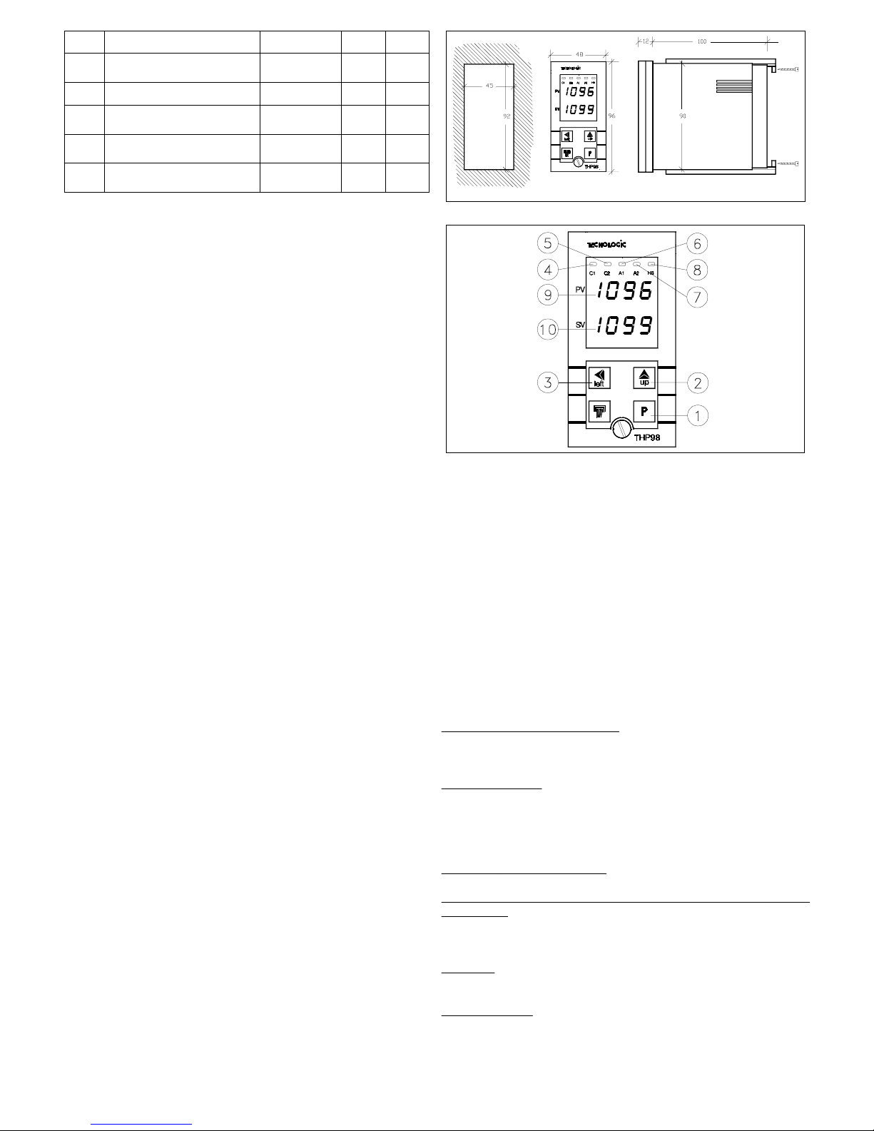
10 ... 20 sec.Costante del filtro digitale in
ingresso
FiLt
0-999 ... 9999
-99.9 ... 999.9
Calibrazione
OFFt
J J / CrAl / r / S
/ t Pt1 / Pt2
Sonda in ingresso
SEnS
CC / F / AbSUnità di misura
Unit
50-99.9 ... 100.0
%
Reset manuale
rS
301 ... 255 sec.Tempo di ciclo uscita C2
tcr2
7 - PROBLEMI, MANUTENZIONE E GARANZIA
SEGNALAZIONI DI ERRORE: I due display vengono utilizzati anche
per visualizzare condizioni anomale di funzionamento dello strumento:
- In caso di interruzione della sonda viene visualizzato "- - - -"
lampeggiante.
- Nel caso la variabile misurata vada al disotto dei limiti della sonda in uso
viene visualizzato "uuuu" lampeggiante.
- Nel caso la variabile misurata vada al disopra dei limiti della sonda in uso
viene visualizzato "oooo" lampeggiante.
In questi casi verificare la corretta connessione della sonda con lo
strumento e successivamente procedere alla verifica della stessa.
- Nel caso l'autotuning sia stato interrotto da una anomalia (sonda
interrotta, ecc.) viene visualizzata la scritta "no Auto" lampeggiante.
- Nel caso l'autotuning non sia terminato dopo un tempo di 4 ore, viene
visualizzata la scritta "tout Auto" lampeggiante.
- Se lo strumento viene spento durante la programmazione, alla successiva
accensione verrà segnalato l'errore di eeprom mediante la visualizzazione
del messaggio "Err EEPr". Per ripristinare il funzionamento occorre
quindi premere contemporaneamente i tasti "P" e "LEFT" e quindi entrare
nella programmazione dei parametri di primo livello e uscirne
regolarmente, anche senza variare i parametri. Tutte le condizioni anomale
disattivano tutte le uscite di regolazione.
PULIZIA: Si raccomanda di evitare l'utilizzo di detergenti abrasivi o
contenenti solventi che possono danneggiare lo strumento.
GARANZIA E RIPARAZIONI: Lo strumento è garantito da vizi di
costruzione o difetti di materiale riscontrati entro i 12 mesi dalla data di
consegna. La garanzia si limita alla riparazione o la sostituzione del
prodotto. L'eventuale apertura del contenitore, la manomissione dello
strumento o l'uso e l'installazione non conforme del prodotto comporta
automaticamente il decadimento della garanzia. In caso di prodotto
difettoso in periodo di garanzia o fuori periodo di garanzia contattare
l'ufficio vendite TECNOLOGIC per ottenere l'autorizzazione alla
spedizione. Il prodotto difettoso, quindi , accompagnato dalle indicazioni
del difetto riscontrato, deve pervenire con spedizione in porto franco presso
lo stabilimento TECNOLOGIC salvo accordi diversi.
1 - GENERAL DESCRIPTION
THP 98 model is a "single loop" digital microprocessor based controller,
with ON/OFF, PID single action, PID double action (direct and inverse)
control mode and with AUTOTUNING function for PID mode. The process
value is visualised by 4 red displays (PV), the set value on 4 green displays
(SV) and the outputs state is indicated by 5 leds. The instrument is foreseen
to have till 5 outputs : 1 or 2 regulation outputs (C1, C2), 1 or 2 alarm
outputs (A1, A2) and 1 Heater Break (HB) alarm output ; all of them are
relays or voltage output to drive solid state relays (SSR). The input accepts
temperature probes as Thermocouple (J,K,R,S,T) or Thermoresistances
(PT100). Furthermore the instrument is available with a current
transformer input for the Heater Break function.
1.1 - FRONT PANEL
1 - Key P : Use to program the functioning parameters and to confirm the
programmed data and pass then to the next parameter.
2 - Key UP: Used to increase the figure on which is placed the "cursor".
(in case of parameters not numerical, "UP" key is needed to select the
available options)
3 - Key LEFT : Used to shift the "cursor" (flashing) on the figure that is
desired to modify, to visualise the current measured by TAHB input and to
reset the alarm latch.
4 - Led C1 : Signalize when the output C1 is on (on) or off (off)
5 - Led C2 : Signalize when the output C2 is on (on) or off (off)
6 - Led A1: Signalize when the output A1 is on (on) or off (off)
7 - Led A2: Signalize when the output A2 is on (on) or off (off)
8 - Led HB: Signalize when the output HB is on (on) or off (off)
9 - Display PV: Normally shows Process Value
10 - Display SV: Normally shows Set Point Value
1.2 - INSTRUMENT CODE
THP 98 T aa bb c d e ff
aa
= Heater Break Alarm Function
-- : Not present
HR : Present with Relay output (HB)
HO : Present with 24 VDC output for SSR driving (HB)
bb
= Alarm Outputs
-- : No Alarm
1R : 1 Alarm with Relay output (A1)
2R : 2 Alarms with Relay output (A1, A2)
1O : 1 Alarm with 24 VDC output for SSR driving (A1)
2O : 2 Alarms with 24 VDC output for SSR driving (A1, A2)
c =
Primary Control Output (C1)
R : Relay output and 24 VDC output for SSR driving
d =
Secondary Control Output for double action Pid control (Heating
and Cooling)
- : Not present
R : Relay Output
O : 24 VDC output for SSR driving
e =
Supply
L : 24 VAC/VDC
H : 90 ... 240 VAC
ff = Special
Codes
TECNOLOGIC - THP 98 USER MANUAL (I - GB) - Vr. 01 - ISTR 00372 - PAG. 7
Page 8
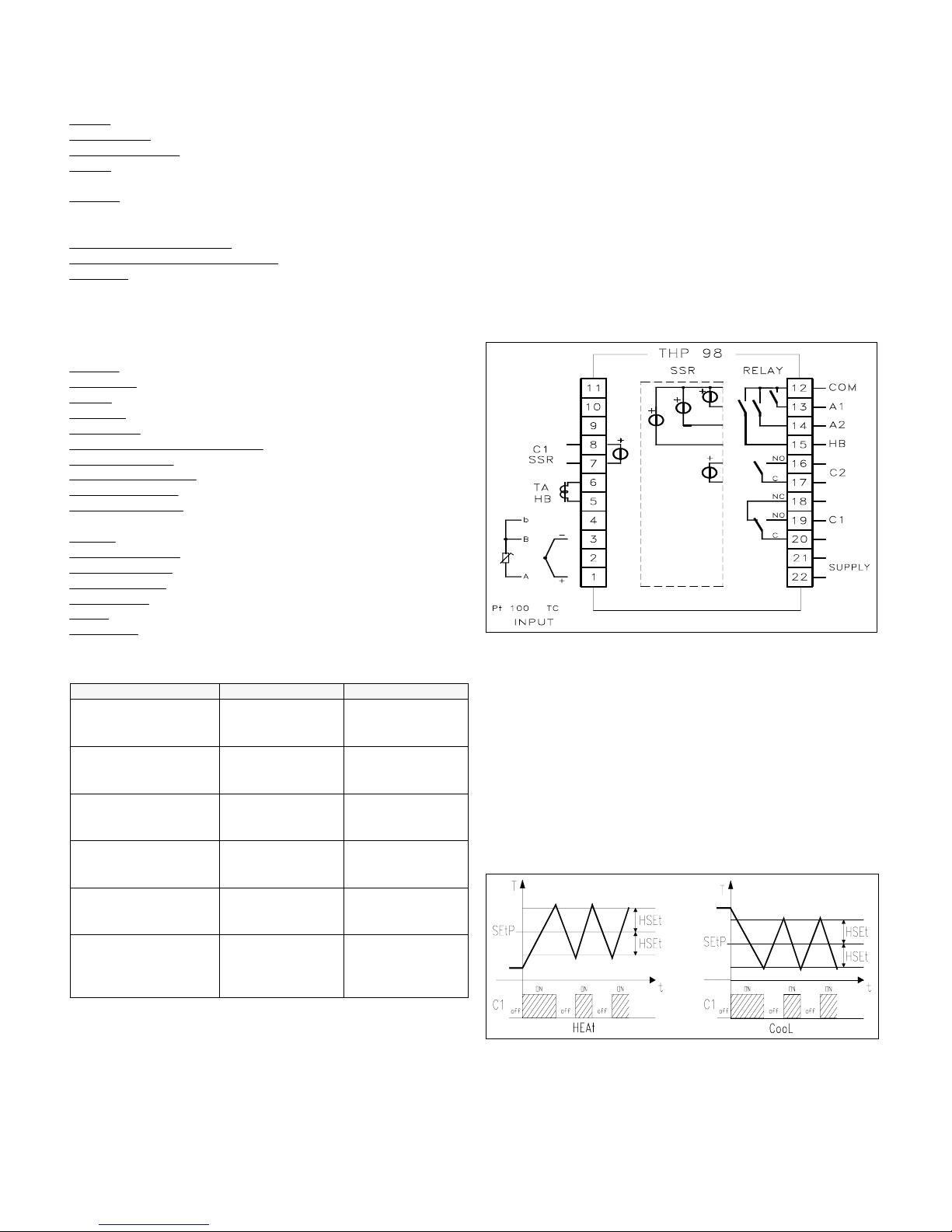
P.A. : All Alarm outputs (A1, A2, HB) have to be of the same type (all
Relay or all 24 VDC for SSR driving )
2 - TECHNICAL DATA
ELECTRICAL DATA
Supply:
24 VAC/VDC, 90 ... 240 VAC +/- 10%
Frequency
AC: 50/60 Hz
Power
consumption: 7 VA approx.
Input/s:
1 input for temperature probes (tc J, K, R, S, T; RTD Pt 100 IEC).
1 input for current transformer with K = 1/0,002 (Max. 200 mA)
Output/s:
Up to 5 outputs. Relay (5 A-AC1, 2 A-AC3 / 250 VAC), 10 A Max
per common (pin 12); or voltage for SSR drive (24VDC/0mA,
14VDC/20mA)
Electrical
life for relay output : 100000 operat.
Protection
class against electric shock: Class II for Front panel
Insulation:
Reinforced insulation between the low voltage section (supply
and relay outputs) and the front panel; Basic insulation between the low
voltage section (supply and relay outputs) and the extra low voltage section
(inputs and outputs for SSR); No insulation between inputs and outputs for
SSR .
MECHANICAL DATA
Housing:
Self-extinguishing plastic, UL 94 V0
Dimensions:
48 x 96 mm DIN, depht 100 mm
Weight:
290 g approx.
Mounting:
Flush in panel in 45 x 92 mm hole
Connections:
6.3 mm Faston terminals
Degree
of protection of front panel : IP 54 mounted in panel with gasket
Pollution
situation: Normal
Operating
temperature: 0 ... 55 °C
Operating
humidity: 30 ... 95 RH% without condesation
Storage
temperature: -10 ... +60 °C
FUNCTIONAL DATA
Control:
ON/OFF, PID
Measurement
range: according to the used probe (see table range)
Display
resolution: according to the probe used 1/0,1
Overall
accuracy: +/- 0,25 % fs
Sampling
rate: 1 sample per second
Action:
1C type according to EN 60730-1
Compliance:
ECC directive EMC 89/336 (EN 50081-1, EN 50082-1), ECC
directive LV 73/23 and 93/68 (EN 60730-1)
MEASUREMENT RANGE TABLE
Pt2
-99.9 ... 850.0 °C
-99.9 ... 999.9 °F
73.0 ... 999.9 K
Pt1
-200 ... 850 °C
-328 ... 1562 °F
73 ... 1123 K
RTD Pt100 IEC
(Pt1, Pt2)
- - - -200 ... 400 °C
-328 ... 752 °F
73 ... 673 K
tc T
(t)
- - - -50 ... 1760 °C
-58 ... 3200 °F
223 ... 2033 K
tc S
(S)
- - - 0 ... 1760 °C
32 ... 3200 °F
273 ... 2033 K
tc R
(r)
- - - -200 ... 1370 °C
-328 ... 2498 °F
73 ... 1643 K
tc K
(CrAl)
- - - -200 ... 870 °C
-328 ... 1598 °F
73 ... 1143 K
tc J
(J)
4 DIGIT with D.P.4 DIGIT PROBE
3 - INSTALLATION
MECHANICAL MOUNTING: The instrument, in DIN case 48 x 96 mm,
is designed for panel mounting. Make an hole 45 x 92 mm and insert the
instrument, fixing it with the provided special brackets . We recommend to
mount the gasket to obtain an IP 54 front protection. Avoid to place the
instrument in areas with humidity or dirt. Connect the instrument as far as
possible from source of electromagnetic disturbances so as motors, power
relays, relays, electrovalves,etc. The instrument is removable from its
housing by the front side : is recommended to disconnect the power supply
from the instrument when is necessary to do this operation.
ELECTRICAL CONNECTIONS: Carry out the electrical wiring
connecting only one wire for each terminal , according to the following
diagram, check that the power supply is the same as indicated on the
instrument and the loads current is not upper than the maximum current
admitted. The instrument, being a built in equipment with permanent
connection into a cabinet, is not furnished with internal device protecting
from overcurrent : it's recommended , therefore, to properly protect all the
electric circuits connected to the instrument, with devices (ex. fuses)
proportionate to the circulating currents. It's strongly recommended to use
cables with proper insulation, according to the working voltages and
temperatures. Furthermore, the input cable of the probe has to be kept
separate from line voltage wiring. If the input cable of the probe is
screened, it has to be connected on the ground with only one side. It is
advisable to check that the parameters are those desired before connecting
the outputs to the actuators so as to avoid malfunctioning . Whenever a
failure of the instrument could cause dangerous or damaging situations, it
should be kept in mind that the plant has to be provided with additional
devices to ensure the safety.
4 - OPERATING MODE
4.1 - ON/OFF CONTROL (C1)
The ON/OFF control mode acts setting parameter "Con1" = "OnOF" and
works on C1 output depending on the set point ("SEtP"), on the functioning
mode ("FunC") and on the hysteresis ("HSEt") programmed.
The instruments proceed with a ON/OFF regulation mode, with symmetric
hysteresis. The regulator, therefore, behave in the following mode : in case
of inverse action or heating mode ("HEAt"), deactivates C1 output when
the temperature reaches the value [SEtP + HSEt] and than actives it again
when temperature goes under the value [SEtP - HSEt] ; on the contrary, in
case of direct action or cooling mode ("CooL"), deactivates C1 output
when the temperature reaches the value [SEtP - HSEt] and than actives it
again when temperature goes upper than the value [SEtP + HSEt].
4.2 - SINGLE ACTION PID CONTROL (C1)
The PID single action regulation mode acts setting parameter "Con1" =
"Pid" and works on C1 output depending on the set point ("SEtP"), on the
functioning mode ("FunC") and on the control algorithm programmed.
TECNOLOGIC - THP 98 USER MANUAL (I - GB) - Vr. 01 - ISTR 00372 - PAG. 8
Page 9
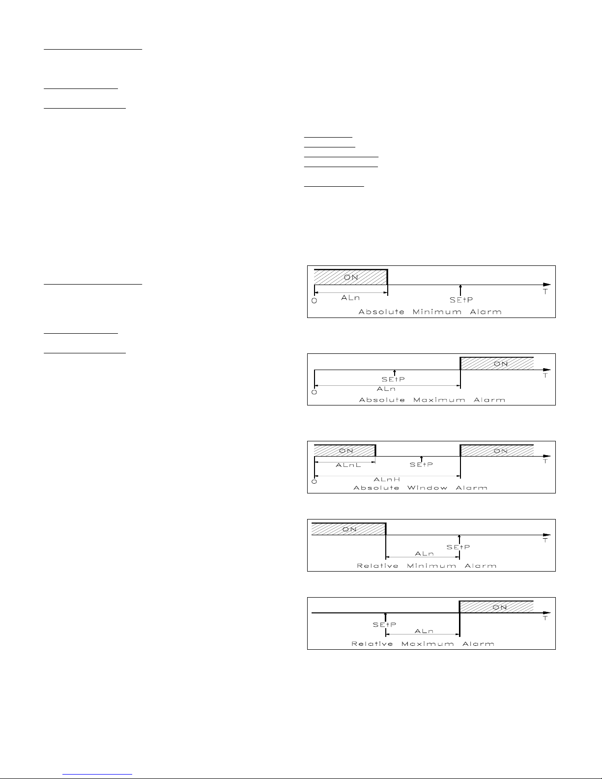
The PID algorithm of the instrument is provided to program the following
parameters:
For
PROPORTIONAL term :
"Pb" - Proportional Band,
"rS" - Manual reset
"tcr1" - Output C1 Cycle time
For
INTEGRAL term:
"Int" - Integral time
For
DERIVATIVE term:
"dEr" - Derivative time
4.3 - DOUBLE ACTION PID CONTROL (C1,C2)
This kind of action can happen only when the instrument has both
regulation outputs (C1 and C2). In this case will not be visualised the
"Con1" parameter, because the only possible regulation mode is PID
double action. This kind of regulation is used to control installations where
there's an element which causes a positive increment (ex. heater) and an
element which causes a negative increment (ex. cooler). With "Func"
parameter will be decided C1 output functioning, while C2 output will
automatically works in the opposite way. For example, if "Func" ="HEAt"
to C1output will be connected the positive increment element (ex. heater)
while to C2 output will be connected the negative increment element (ex.
cooler). PID double action mode acts, therefore, on C1 and C2 outputs and
depending on Set point ("SEt") and on control algorithm programmed.
The PID algorithm of the instrument is provided to program the following
parameters:
For
PROPORTIONAL term :
"Pb" - Proportional Band,
"rS" - Manual reset
"tcr1" - Output C1 Cycle time
"tcr2" - Output C2 Cycle time
For
INTEGRAL term:
"Int" - Integral time
For
DERIVATIVE term:
"dEr" - Derivative time
Furthermore the parameter "Prat" (Power Ratio), on which it's necessary
to set the ratio between power of the element controlled by C2 output and
power of the element controlled by C1 output. If ever the parameter "Prat"
is = 0, C2 output is deactivated and the regulator behave exactly as a PID
single action, trough C1 output.
4.4 - AUTOTUNING FUNCTION
The instrument is set on parameters relative to PID control of standard
value. If ever these should result to be unsuitable it would be advisable to
program the AUTOTUNING function. The Autotuning function permits the
automatic tuning of the PID instrument parameters, whether single or
double action.
To active the AUTOTUNING function proceed as follows :
1) Set the desired "Set point".
2) Set, if present, "Con1" parameter = "Pid".
3) Set "Func" parameter depending on the process to be controlled, trough
C1output.
4) Connect the instrument with the plant
5) Set the parameter "Auto" as :
- "Sp" if it's desired to have autotuning on Set Point value programmed, or
:
- "LoSp" if it's desired to have autotuning on a lower value (equal to 70%
of Set Point programmed)
6) Go out of parameters programming
Now, the Autotuning function is activated and it's shown by the flashing of
the two external decimal point on the lower display (SV). The regulator
automatically tunes all the right parameters for a correct PID control
mode. Before to switch off the instrument always wait for the end of the
Autotuning process, indicated by the return of the display on the normal
functioning. During the autotuning execution are activated some ON-OFF
regulation cycles, that consequently make temperature swing abundantly
around set point value (a bigger or smaller temperature swing depends on
the process nature to be controlled and not on the instrument). If the
process doesn't allow to big temperature variations upper than set point
value, it's advisable to select autotuning cycle as "LoSP". The Autotuning
procedure has been limited at a maximum time of 4 hours, after this time, if
the Autotuning is not completed the instrument automatically get out from
the procedure, showing constantly on the display "tout Auto". In case,
instead, should happen an anomaly during autotuning, the instrument will
visualise "no Auto" flashing. To stop the Autotuning cycle or re-establish
the normal functioning after an error, switch off and on the instrument.
The calculated values will be automatically memorised by the instrument
at the end of the Autotuning cycle, in the PID control parameters.
4.5 - ALARM OUTPUTS OPERATING MODE (A1,A2)
To configure the alarms functioning, whom activation is depending on the
process value (A1,A2), it's necessary to set "rL1" ("rL2") with a code made
by 4 figures as following composed : a b c d where :
a :
Alarm type
b : Alarm latch
c : Start-up behaviour
d : Output logic mode
a - ALARM TYPE
It's possible to have 6 different alarm output behaviours, depending on the
value of the first code figure.
Note : Here following we'll indicate, in the examples, "ALn" to intend a
generic alarm (AL1 or AL2). Furthermore, when it's programmed the
window alarm type , instead of "ALn" will appear two parameters "ALnL"
(Lower set) and "ALnH" (Higher set).
0 = ABSOLUTE MINIMUM ALARM: The alarm is activated when the
process value goes under the alarm set programmed on "ALn" parameter.
1 = ABSOLUTE MAXIMUM ALARM: The alarm is activated when the
process value goes upper than the alarm set programmed on "ALn"
parameter.
2 = ABSOLUTE WINDOW ALARM: The alarm is activated when the
process value goes under the alarm set programmed on "ALnL" parameter
or goes upper than the alarm set programmed on "ALnH" parameter.
3 = RELATIVE MINIMUM ALARM: The alarm is activated when the
process value goes under the value [SEtP - ALn ].
4 = RELATIVE MAXIMUM ALARM: The alarm is activated when the
process value goes upper than the value [SEtP + ALn ].
5 = RELATIVE WINDOW ALARM: The alarm is activated when the
process value goes under the value [SEtP - ALnL ] or goes upper than the
value [SEtP + ALnH ].
TECNOLOGIC - THP 98 USER MANUAL (I - GB) - Vr. 01 - ISTR 00372 - PAG. 9
Page 10
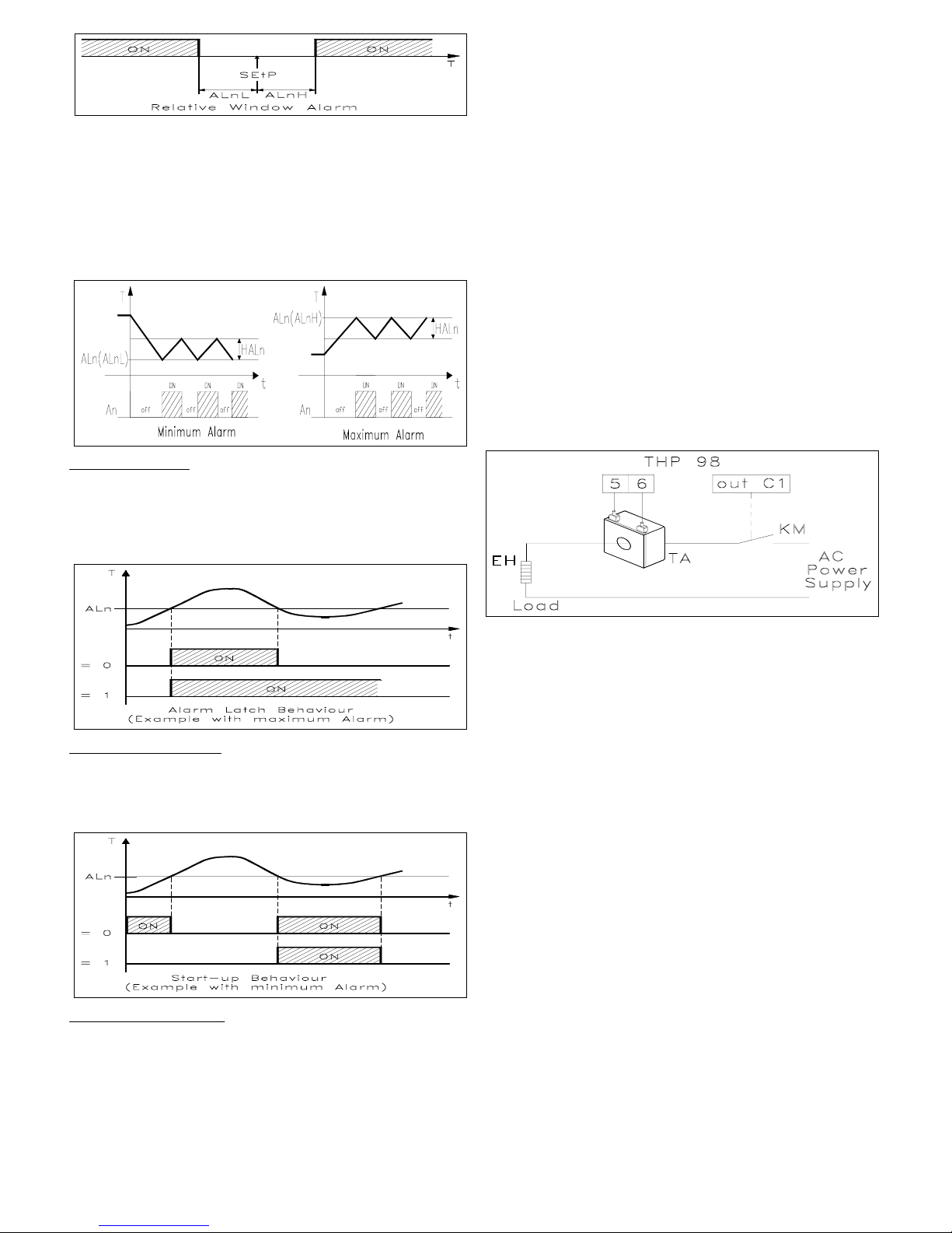
ALARMS HYSTERESIS: The alarms functioning depends furthermore on
the alarms hysteresis ("HALn" parameter), which works in asymmetric
mode. More precisely, in case of minimum alarm, the alarm will be
activated when the process value goes under the alarm set and will be
deactivated when it goes upper than the alarm set + "HALn"; in case of
maximum alarm, the alarm will be activated when the process value goes
upper than the alarm set and will be deactivated when it goes under the
alarm set - "HALn". In case of window alarms, the minimum alarm
example is applicable to the lowest set ("ALnL") while the maximum alarm
example is applicable to the higher set ("ALnH").
b - ALARM LATCH: It's possible to have 2 different alarm output
behaviours, depending on the value of the second figure code.
0 = ALARM NOT LATCHED: The alarm remains active only in alarm
conditions.
1 = ALARM LATCHED: The alarm is activated when there are alarm
conditions and remains active although these conditions are not existing
anymore, till is not pushed the "LEFT" key.
c- START-UP BEHAVIOUR: It's possible to have 2 different alarm output
behaviours, depending on the value of the third figure code.
0 = NORMAL BEHAVIOUR: The alarm is always activated when there are
alarm conditions.
1 = ALARM NOT ACTIVE AT START-UP: If at start-up the instrument is
in alarm conditions this is not activated.
d - OUTPUT LOGIC MODE: It's possible to have 2 different alarm output
behaviours, depending on the value of the fourth figure code.
1 = OUTPUT ON IN ALARM CONDITIONS: The output is activated when
the alarm is active, while is deactivated while the alarm is not active.
0 = OUTPUT OFF IN ALARM CONDITIONS: The output is activated
when the alarm is not active, while is deactivated while the alarm is active.
4.6 - HEATER BREAK ALARM FUNCTION (HB)
The instrument can be furnished with the Heater Break alarm function.
(Alarm in case of broken heating element ), in this case it will have an
input (TAHB) able to measure the load current driven by C1 output. This
kind of input accepts signals coming from current transformers (TA) till a
maximum of 200 mA (at 200 mA the instrument measure a value of 100.0).
Therefore, to obtain the correct Ampere measure it will occur that TA ratio
would be 1/0,002. Tecnologic can supply 2 standard models : TR 03536 :
25A / 0,05 A, TR 03537 : 100 A / 0,2 A . During the functioning it's
possible to visualise on SV display the current measured by TAHB input,
expressed in Ampere (if obviously the TA ratio is 1/0,002) pushing "LEFT"
key. The alarm will be active when, in C1output active conditions, the
current measured by TAHB input will results lower than the value set on
"ALHb" parameter. "ALHb" parameter has to be programmed with the
value of the current normally taken over by the load driven by C1 output,
considering as well the network tension fluctuations , in order to avoid
undesired alarms. As regard the HB alarm hysteresis it's automatically
calculated by the instrument as 2% of "ALHb" and the behaviour is the
same as a minimum alarm. If it's desired to deactivate the HB alarm, it's
enough to program "ALHb" = 0.0.
It's possible to have 2 different HB alarm output behaviours, depending on
the "rLHb" parameter programmed.
"nO" = NORMALLY OPENED: The output is activated when the alarm is
active, while is deactivated when the alarm is not active.
"nC" = NORMALLY CLOSED: The output is activated when the alarm is
not active, while is deactivated when the alarm is active.
Notes : The current measure trough TAHB input needs at least 100 mS.
5 - PROGRAMMING
Push key "P" and keep it pushed for about 2 seconds, the instrument will
show on the higher display PV the code of the first parameter ("SEtP") and
on the lower display SV the programmed value with one figure flashing.
This indicates that it's possible to modify it pushing "UP" key. When it's
desired to modify a different figure it's necessary to select it, by means of
"LEFT" key and then modify it using "UP" key. Once set the desired value
pushing key "P" on the display will be shown the code of the next
parameter. Working on "LEFT" and "UP" keys, as above described, is then
possible to modify it. Once set the desired values push key "P" several
times till the instrument goes out of the parameters programming, going
back to the normal conditions of functioning visualising the process value
on display PV and the Set Point value on display SV. Otherwise the
instrument goes automatically out from the programming mode after about
50 seconds starting by the moment of the last push on the keys. The last
parameter of the first level which appears on PV display is "PASS" : this is
the request of the PASSWORD to accede to the second level parameters. To
do this it's necessary to set, on Password request, the number written on
the last page of this manual, and then push "P" key. If it's set the wrong
Password the instrument goes out from the programming. The modality of
programming of the second level parameters and the operations to go out
by them are exactly the same as described for the first level parameters.
P.A.: During the instrument programming the regulation is not activated
and the alarm outputs remain in the original conditions, as before the
programming input. Always go out regularly from the programming phase
because, if the instrument is switched-off during the programming, at the
next switching-on will be signalised a memory error, visualised by the
message "Err EEPr". To re-establish the functioning is needed therefore to
push, at the same time, "P" and "LEFT" keys and then get into the first
level parameter programming, go out regularly, even if no parameters are
changed. When programming operating parameters some parameters will
TECNOLOGIC - THP 98 USER MANUAL (I - GB) - Vr. 01 - ISTR 00372 - PAG. 10
Page 11

not displayed, this happens because the instrument is predisposed to
automatically not visualise the unnecessary parameters.
6 - DESCRIPTION OF PARAMETERS
Here following are described all the instrument parameters; pls. note that
some of them could do not appear or because are according to the kind of
used instrument or because are automatically not qualified, as they're not
necessary.
FIRST LEVEL PARAMETERS
SEtP - SET POINT : Regulation value of Set Point
HSEt - SET POINT HYSTERESIS ( ON/OFF CONTROL MODE) :
Symmetric semi-band relative to the Set Point, which decides the C1
outputs activation and deactivation, when the regulation mode is ON/OFF.
This parameter do appear just whether the programmed regulation is
ON/OFF type ("Con1" = "OnOF").
PASS - PASSWORD REQUEST : Used to set the password that permits to
accede to the second level parameters.
FIRST OR SECOND LEVEL PARAMETERS
The following parameters are normally present in the first level, but can be
moved in the second level by means of parameter "ALPr" = "yES".
AL1 - ALARM A1 THRESHOLD (MINIMUM OR MAXIMUM ALARM) :
A1 alarm threshold for minimum or maximum alarms.
AL1L - MINIMUM ALARM A1 THRESHOLD (WINDOW ALARM) : A1
alarm threshold working as minimum alarm when it's set a window alarm
type. AL1H - MAXIMUM ALARM A1 THRESHOLD (WINDOW ALARM)
: A1 alarm threshold working as maximum alarm when it's set a window
alarm type.
HAL1 - ALARM A1 HYSTERESIS : Asymmetric semi-band referred to A1
alarm value, that establish the deactivation value of A1 alarm.
AL2 - ALARM A2 THRESHOLD (MINIMUM OR MAXIMUM ALARM) :
Equal to "AL1", but referred to A2 alarm.
AL2L - MINIMUM ALARM A2 THRESHOLD (WINDOW ALARM) :
Equal to "AL1L", but referred to AL2 alarm.
AL2H - MAXIMUM ALARM A2 THRESHOLD (WINDOW ALARM) :
Equal to "AL1H", but referred to AL2 alarm.
HAL2 - ALARM A2 HYSTERESIS : Equal to "HAL1", but referred to AL2
alarm.
ALHb - HEATER BREAK ALARM THRESHOLD : Activation set of
Heater Break alarm.
SECOND LEVEL PARAMETERS
rL1 - ALARM A1 OPERATION MODE : Permits to decide the alarm A1
functioning mode, trough the setting of a code, composed by 4 figures (see
alarm output functioning).
rL2 - ALARM A2 OPERATION MODE : Equal to "rL1", but referred to
AL2 alarm.
rLHb - OUTPUT HB LOGIC MODE : Permits to establish the Heater
Break alarm functioning mode, setting the output rest state ("nO" =
normally opened, "nC" = normally closed)
FAIL - ALARM ON FOR ERROR INSTRUMENT :Permits to decide in
which error conditions no alarm has to be activated ("no"), has to be
activated A1 alarm ("rL1"), has to be activated A2 alarm ("rL2") or both
("rL12").
dAL1 - DISCONNECTION OF ALARM A1 : Permits to disable A1 alarm
output ("yES"). Disabling the output, in alarm conditions, the alarm led
will flash and the output will not be activated. Otherwise ("no") the output
will function normally.
dAL2 - DISCONNECTION OF ALARM A2 : Equal to "dAL1", but referred
to AL2 alarm.
ALPr - ALARM PROGRAMMING AT FIRST OR SECOND LEVEL
PARAMETERS : Permits to make visible the alarm setting parameters of
the first ("no") or second ("yES") level.
SPLL - LOW/MINIMUM SET POINT : Minimum possible Set Point value
or lower limit of Set point.
SPHL - HIGH/MAXIMUM SET POINT : Maximum possible Set Point
value or higher limit of Set point.
Con1 - CONTROL MODE : Permits to select one of the possible regulation
mode offered by the instrument : ON/OFF ("OnOF") or PID ("Pid"). This
parameter is not visible in the instruments with 2 regulation outputs (C1
and C2) because in these models the only possible regulation is PID mode
for both outputs.
Func - OUTPUT C1 OPERATING MODE : Permits to decide if C1
regulation mode has to control an Heating process ("HEAt") or a Cooling
process ("CooL"). In the instruments with 2 regulation outputs (C1 and
C2) this parameter automatically determines the C2 output opposite action
to the one set at "Func" parameter.
Auto - AUTOTUNING : Parameter used to carry on an Autotuning cycle,
that permits the automatic tune of the right PID regulation parameters. It's
possible effect the Autotuning at the real Set Point value ("SP") or at a
reduced value, equal to 70% of the Set Point ("LoSP"). If it's not desired to
have the Autotuning, set "no".
Pb - PROPORTIONAL BAND : Band width around Set Point on which
works the proportional regulation.
Int - INTEGRAL TIME : Integral time to be set in the PID regulation
algorithm, expressed in seconds.
dEr - DERIVATIVE TIME : Derivative time to be set in the PID regulation
algorithm, expressed in seconds.
tcr1 - OUTPUT C1 CYCLE TIME : Cycle time referred to C1 output , when
intervenes the proportional regulation on PID regulation mode, expressed
in seconds.
Prat - C2 / C1 POWER RATIO : Setting of power ratio between the
element controlled by C2 output (ex, Cooler) and power of the element
controlled by C1 output (ex. Heater) when the instrument has both C1 and
C2 regulation outputs.
tcr2 - OUTPUT C2 CYCLE TIME : Cycle time referred to C2 output , when
intervenes the proportional regulation on PID regulation mode, expressed
in seconds.
rS - MANUAL RESET : Proportional band positioning referred to the Set
Point, expressed in percentage value.
Unit - UNIT OF MEASUREMENT : Permits to decide if the visualisation is
expressed in Degree Centigrade ("C"), Fahrenheit ("F") or Kelvin ("AbS").
Pls. note : modifying this parameter results modified the display
visualisation but not the Set Point and all the other parameters expressing
the temperature values, and therefore they have to be manually modified.
For example, if Set Point = 50°C and the unit of measurement is changed
into °F, Set Point will be 50 °F.
SEnS - INPUT PROBE : Permits to select the kind of input probe :
thermocouples J ("J"), K ("CrAl"), R ("r"), S ("S"), T ("t") or
thermoresistances PT100 with no decimal point visualisation ("Pt1") or
with decimal point visualisation ("Pt2")
OFFt - CALIBRATION : Positive or negative Offset that is addicted to the
probe detected value , first than the visualisation, on which is depending as
well the functioning regulation. This parameter can be necessary to
recalibrate the instrument.
FiLt - INPUT DIGITAL FILTER CONSTANT : Time constant of the
software filter, referred to the input value measurement, expressed in
seconds.
6.1 - PARAMETERS TABLES
FIRST LEVEL PARAMETERS TABLE
00.0 ... 100.0Heater Break alarm threshold
ALHb
10 ... 9999
0.0 ... 999.9
Alarm A2 hysteresis
HAL2
0-999 ... 9999
-99.9 ... 999.9
Maximum Alarm A2 threshold
(window alarm)
AL2H
0-999 ... 9999
-99.9 ... 999.9
Minimum Alarm A2 threshold
(window alarm)
AL2L
0-999 ... 9999
-99.9 ... 999.9
Alarm A2 threshold
(minimum or maximum alarm)
AL2
10 ... 9999
0.0 ... 999.9
Alarm A1 hysteresis
HAL1
0-999 ... 9999
-99.9 ... 999.9
Maximum Alarm A1
threshold(window alarm)
AL1H
0-999 ... 9999
-99.9 ... 999.9
Minimum Alarm A1 threshold
(window alarm)
AL1L
0-999 ... 9999
-99.9 ... 999.9
Alarm A1 threshold
(minimum or maximum alarm)
AL1
10 ... 9999
0.0 ... 999.9
Set point hysteresis ( ON/OFF
control mode)
HSEt
0SPLL ÷ SPHLSet point
SEtP
NotesDef.RangeDescriptionPar.
TECNOLOGIC - THP 98 USER MANUAL (I - GB) - Vr. 01 - ISTR 00372 - PAG. 11
Page 12

0000 ... 9999Password request second level
programming parameters
PASS
SECOND LEVEL PARAMETERS TABLE
10 ... 20 sec.Input digital filter costant
FiLt
0-999 ... 9999
-99.9 ... 999.9
Calibration
OFFt
J J / CrAl / r / S
/ t Pt1 / Pt2
Input probe
SEnS
CC / F / AbSUnit of measurement
Unit
50-100.0 ... 100.0
%
Manual reset
rS
301 ... 255 sec.Output C2 cycle time
tcr2
100.0 ... 999.9C2 / C1 power ratio
Prat
301 ... 255 sec.Output C1 cycle time
tcr1
300 ... 9999 sec.Derivative time
dEr
5000 ... 9999 sec.Integral time
Int
1001 ... 9999Proportional band
Pb
nono / SP / LoSPAutotuning
Auto
HEAtHEAt / CooLOutput C1 operating mode
Func
PidPid / OnOFControl mode
Con1
9999SPLL ... 9999
SPLL ... 999.9
High/maximum Set point
SPHL
-999-999 ... SPHL
-99.9 ... SPHL
Low/minimum Set Point
SPLL
nono / yESAlarm programming at first or
second level parameters
ALPr
nono / yESDisconnection of alarm A2
dAL2
nono / yESDisconnection of alarm A1
dAL1
norL1 - rL2
rL12 - no
Alarm on for error instrument
FAIL
nOnO - nCOutput HB logic mode
rLHb
00000000 ... 5111Alarm A2 operation mode
rL2
00000000 ... 5111Alarm A1 operation mode
rL1
NotesDef.RangeDescriptionPar.
7 - PROBLEMS, MAINTENANCE AND WARRANTY
ERRORS SIGNALLING : The 2 displays are used as well to visualise
anomaly conditions of instrument functioning :
- In case of probe interruption it's visualised "- - - -" flashing.
- In case the measured variable goes under the probe limits it's visualised
"uuuu" flashing.
- In case the measured variable goes upper under the probe limits it's
visualised "oooo" flashing.
In these cases verify the correct connection of the probe with the
instrument and afterward proceed to verify the probe itself.
- In case the Autotuning has been interrupted by an anomaly (probe
interruption, etc.) it's visualised "no Auto" flashing.
- In case the Autotuning is not ended within 4 hours, it's visualised "tout
Auto" flashing.
- If the instrument has been switched-off during the programming, at the
next switching-on will be signalised the eeprom memory error, appearing
the message "Err EEPr". To re-establish the right functioning it's
necessary to push contemporary the "P" and "LEFT" keys and then get into
parameter programming of the first level, go out regularly, even if no
parameters are changed.
All the anomaly conditions will de-active all the regulation outputs.
HOW TO CLEAN: We recommend to avoid abrasive cleaners or
containing solvents which could damage the instrument.
WARRANTY AND REPAIRS: The instrument is under warranty against
construction vices or defected material, noticed within 12 months from
delivery date.The warranty is limited to the repairs or to the substitution of
the instrument. The eventual opening of the housing, the violation of the
instrument or the wrong use and installation of the product means the
automatically decay of the warranty. In case of defected instrument,
noticed in warranty period or out of warranty, do contact our sales
department to obtain the shipment authorisation. The defected product
must be shipped to TECNOLOGIC with the detailed description of the
failures found and without any fees or charge for Tecnologic, safe
different agreements.
THP 98 PASSWORD = 0381
TECNOLOGIC - THP 98 USER MANUAL (I - GB) - Vr. 01 - ISTR 00372 - PAG. 12
 Loading...