

Page 1

THP 24
REGOLATORE ELETTRONICO
DIGITALE A MICROPROCESSORE
MICROPROCESSOR-BASED DIGITAL
ELECTRONIC CONTROLLER
ISTRUZIONI PER L'USO
OPERATING INSTRUCTIONS
Vr. 01 (I - GB) - cod.: ISTR 00239
TECNOLOGIC S.p.A.
VIA INDIPENDENZA 56
27029 VIGEVANO (PV) ITALY
TEL.: ++39 0381 69871 - FAX: ++39 0381 698730
internet : http:\\www.tecnologic.it
e-mail: [email protected]
PREMESSA: Nel presente manuale sono contenute le informazioni
necessarie ad una corretta installazione e le istruzioni per l'utilizzo e la
manutenzione del prodotto, si raccomanda pertanto di leggere attentamente
le seguenti istruzioni. Ogni cura è stata posta nella realizzazione di questa
documentazione, tuttavia la TECNOLOGIC S.p.A. non può assumersi
alcuna responsabilità derivante dall'utilizzo della stessa. Lo stesso dicasi
per ogni persona o società coinvolta nella creazione del presente manuale.
La presente pubblicazione è di esclusiva proprietà della TECNOLOGIC
S.p.A. la quale pone il divieto assoluto di riproduzione e divulgazione,
anche parziale, se non espressamente autorizzata. La TECNOLOGIC S.p.A.
si riserva di apportare modifiche estetiche e funzionali in qualsiasi
momento e senza alcun preavviso.
PREVIOUS STATEMENT: In this manual are contained all the necessary
information for a correct installation and the instructions for the use and
the maintenance of the product; we recommend, therefore, to read
carefully the following instructions. The maximum care has been used in
the realisation of this document, anyway TECNOLOGIC S.p.A. does not
assume any responsibility deriving from the use of itself. The same
consideration has to be done for each person or Company involved in the
creation of this manual. The herewith issue is an exclusive property of
TECNOLOGIC S.p.A. which forbids any reproduction and divulgation,
although partial, if not expressly authorised. TECNOLOGIC S.p.A.
reserves the right to execute aesthetically and functional modifications, at
any moment and without any notice.
INDICE
PROBLEMI , MANUTENZIONE E GARANZIA7
TABELLA PARAMETRI6.1
DESCRIZIONE DEI PARAMETRI6
IMPOSTAZIONE DEI LIMITI DI INGRESSO5.3
PROGRAMMAZIONE DEI PARAMETRI5.2
IMPOSTAZIONE DEL SET POINT5.1
PROGRAMMAZIONE5
FUNZIONE SET POINT DINAMICO4.4
REGOLATORE PID E FUNZIONE DI AUTOTUNING4.3
REGOLATORE A ZONA NEUTRA4.2
REGOLATORE ON/OFF4.1
FUNZIONAMENTO4
INSTALLAZIONE3
DATI TECNICI2
CODIFICA DELLO STRUMENTO1.2
PANNELLO FRONTALE1.1
DESCRIZIONE GENERALE1
INDEX
TROUBLES, MAINTENANCE, GUARANTEE7
PARAMETERS TABLE6.1
DESCRIPTION OF PARAMETERS6
PROGRAMMING OF INPUT LIMITS5.3
PROGRAMMING OF PARAMETERS5.2
PROGRAMMING OF SET-POINT5.1
PROGRAMMING5
DYNAMIC SET POINT FUNCTION4.4
PID CONTROL AND AUTOTUNING FUNCTION4.3
NEUTRAL ZONE CONTROL4.2
ON/OFF CONTROL4.1
OPERATING MODE4
INSTALLATION3
TECHNICAL DATA2
INSTRUMENT CODE1.2
FRONT PANEL1.1
GENERAL DESCRIPTION1
1 - DESCRIZIONE GENERALE
Il modello THP 24 è un regolatore digitale a microprocessore con 1 o 2 Set
point, regolazione ON/OFF, PID o a ZONA NEUTRA e con funzione di
AUTOTUNING per la regolazione PID. Il valore di processo viene
visualizzato su 4 display rossi mentre lo stato delle uscite viene segnalato
da due led. Lo strumento prevede sino a 2 uscite, 1 a relè e 1 per il
pilotaggio di relè statici (SSR) e un ingresso per sonde di temperatura del
tipo PTC (KTY 81), o RTD (Pt100 o Ni100), o Termocoppie (J, K, S) o
per sonde di qualsiasi tipo aventi uscita normalizzata in corrente o in
tensione 4..20 mA, 0..20 mA o 0..10 V.
1.1
-
PANNELLO FRONTALE
TECNOLOGIC - THP 24 USER MANUAL (I - GB) - Vr. 01 - ISTR 00239 - PAG. 1
Page 2

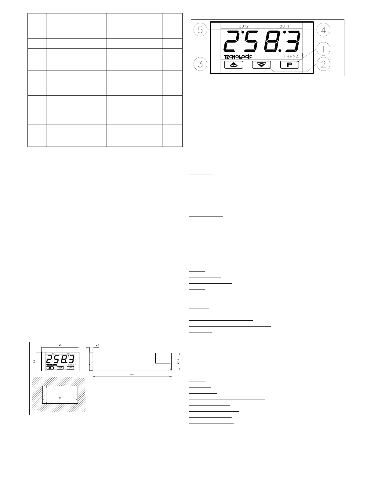
1 - Tasto P : Utilizzato per l'impostazione del set point e per la
programmazione dei parametri di funzionamento
2 - Tasto DOWN : Utilizzato per il decremento dei valori da impostare o
per la selezione dei parametri
3 - Tasto UP : Utilizzato per l'incremento dei valori da impostare o per la
selezione dei parametri
4 - Led OUT1 : Indica lo stato dell'uscita OUT1 on (acceso), off (spento) e
l'ingresso in programmazione Set1 o parametri (lampeggiante).
5 - Led OUT2 : Indica lo stato dell'uscita OUT2 on (acceso), off (spento) e
l'ingresso in programmazione Set2
1.2 - CODIFICA DELLO STRUMENTO
THP 24 a b cc dd
a = ALIMENTAZIONE
L : 24 VAC/VDC
H : 90 ... 240 VAC
b = INGRESSO
C : Termocoppie (J, K, S)
D : Termoresistenze (Pt100, Ni100 IEC)
E : Termistori PTC (KTY 81)
F : Segnali normalizzati 4..20 mA
A : Segnali normalizzati 0..20 mA
V : Segnali normalizzati 0..10 V
cc = USCITE
OR : OUT 1 in tensione 6 VDC per SSR, OUT2 a relè
RO : OUT 1 a relè, OUT2 in tensione 6 VDC per SSR
O- : OUT 1 in tensione 6 VDC per SSR, OUT2 non presente
R- : OUT 1 a relè, OUT2 non presente
dd
= CODICI SPECIALI
2 - DATI TECNICI
CARATTERISTICHE ELETTRICHE
Alimentazione:
24 VAC/VDC, 90 ... 240 VAC +/- 10%
Frequenza AC:
50/60 Hz
Assorbimento:
3 VA circa
Ingresso/i:
1 ingresso. Per sonde di temperatura tc J, K, S o RTD Pt 100
IEC, Ni 100 o PTC (KTY 81-121 990 Ω a 25 °C) o per segnali
normalizzati 4..20 mA, 0..20 mA o 0..10 V
Uscita/e:
Sino a 2 uscite. 1 a relè (5A-AC1, 2A-AC3 250 VAC) ; 1 in
tensione per pilotaggio SSR (6 VDC/15 mA)
Vita elettrica uscite a relè:
100000 operaz.
Classe di protezione contro le scosse elettriche:
Frontale in Classe II
Isolamenti:
Rinforzato tra parti in bassa tensione (alimentazione e uscite a
relè) e frontale; Principale tra parti in bassa tensione (alimentazione e uscite
a relè) e parti in bassissima tensione (ingresso e uscite statiche); Nessun
isolamento tra ingresso e uscite statiche
CARATTERISTICHE MECCANICHE
Contenitore:
Plastico autoestinguente UL 94 V0
Dimensioni:
24 x 48 mm DIN, prof. 100 mm
Peso:
80 g circa
Installazione:
Incasso a pannello in foro 22 x 45 mm
Connessioni:
Morsettiera a vite 2,5 mm2 estraibile
Grado di protezione frontale:
IP 54 con guarnizione
Situazione di polluzione:
Normale
Temperatura ambiente di funzionamento:
0 ... 55 °C
Umidità ambiente di funzionamento:
30 ... 95 RH% senza condensazione
Temperatura di trasporto e
immagazzinaggio: -10 ... +60 °C
CARATTERISTICHE FUNZIONALI
Regolazione:
ON/OFF, ZONA NEUTRA, PID
Range
di misura: Secondo la sonda utilizzata (vedi tabella)
Risoluzione visualizzazione:
Secondo la sonda utilizzata. 1/0,1/5/0,5
Precisione totale:
+/- 0,5 % fs
Velocità di acquisizione:
1 acquisizione al secondo
Azione:
tipo 1C secondo EN 60730-1
Conformita':
Direttiva CEE EMC 89/336 (EN 50081-1, EN 50082-1),
Direttiva CEE BT 73/23 e 93/68 (EN 60730-1)
TABELLA RANGE DI MISURA
-50.0 ... +150.0 °C
-58.0 ... +302.0 °F
-50 ... +150 °C
-58 ... +302 °F
PTC
4 DIGIT with D.P.4 DIGIT PROBE
-99.9 ... 700.0- 999 ... 7000
4..20 mA, 0..20 mA,
0..10 V (gener.)
---0 ... +1600 °C
+32 ... +2912 °F
tc S (rh)
---0 ... +1200 °C
+32 ... +2192 °F
tc K (Cr)
---0 ... +800 °C
+32 ... 1472 °F
tc J (FE)
-50.0 ... +150.0 °C
-58.0 ... +302.0 °F
-50 ... +150 °C
-58 ... +302 °F
Ni 100 (ni)
-99.9 ... +600.0 °C
-99.9 ... +999.9 °F
-100 ... +600 °C
-148 ... +1112 °F
Pt 100 (Pt)
3 - INSTALLAZIONE
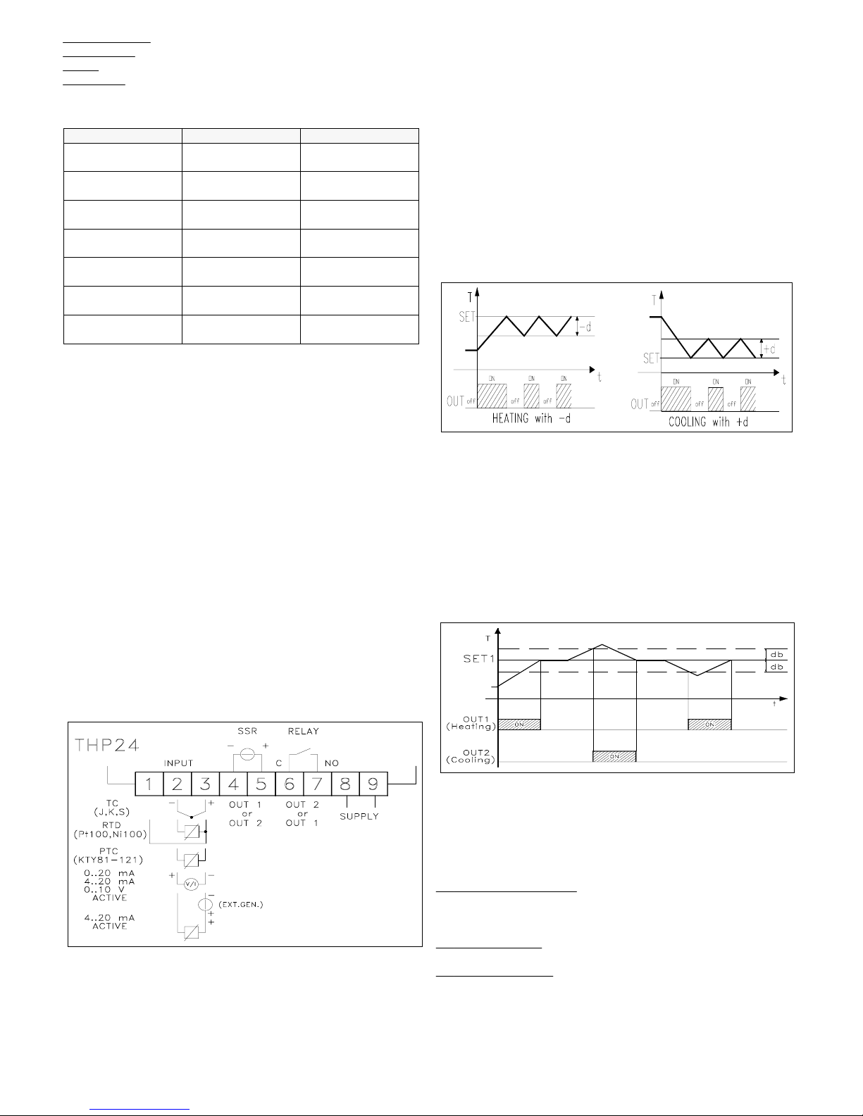
MONTAGGIO MECCANICO: Lo strumento, in contenitore DIN 24 x
48 mm, è concepito per il montaggio ad incasso a pannello. Praticare
quindi un foro 22 x 45 mm ed inserirvi lo strumento fissandolo con
l'apposita staffa fornita. Si raccomanda di montare l'apposita guarnizione
per ottenere il grado di protezione frontale IP54. Evitare di collocare la
parte interna dello strumento in luoghi soggetti ad alta umidità o sporcizia.
Installare lo strumento il più lontano possibile da fonti che possono
generare disturbi elettromagnetici e quindi anche da motori, teleruttori, relè,
elettrovalvole ecc.
COLLEGAMENTI ELETTRICI: Effettuare le connessioni collegando
un solo conduttore per morsetto e seguendo lo schema riportato,
controllando che la tensione di alimentazione sia quella indicata sullo
strumento e che l'assorbimento degli attuatori collegati allo strumento non
sia superiore alla corrente massima consentita. Lo strumento, essendo
previsto per collegamento permanente entro un'apparecchiatura, non è
dotato di dispositivi interni di protezione da sovracorrenti, si raccomanda
pertanto di proteggere adeguatamente tutti i circuiti connessi allo strumento
con dispositivi (es. fusibili) adeguati alle correnti circolanti. Si raccomanda
di utilizzare cavi con isolamento appropriato alle tensioni e alle temperature
di esercizio e di fare in modo che il cavo di ingresso della sonda sia tenuto
distante dai cavi di alimentazione e da altri cavi di potenza. Se il cavo di
ingresso della sonda è schermato è preferibile collegarlo a terra da un solo
lato. Si consiglia di controllare che i parametri impostati siano quelli
desiderati prima di collegare le uscite agli attuatori onde evitare anomalie o
danneggiamenti dell'impianto controllato. Qualora un guasto
dell'apparecchio possa creare situazioni pericolose o dannose si ricorda che
l'impianto deve essere predisposto con dispositivi elettromeccanici
aggiuntivi per garantire la sicurezza.
4 - FUNZIONAMENTO
4.1 - REGOLATORE ON/OFF
Il modo di regolazione dello strumento di tipo ON/OFF agisce sulle uscite
in funzione dei Set point impostati, dei differenziali di intervento (par.
"d1"e "d2") e dei modi di funzionamento (par. "HC1"e "HC2")
programmati. Per un corretto funzionamento programmare un differenziale
negativo per un controllo di tipo inverso (es. Riscaldamento) e positivo per
un controllo di tipo diretto (es. Refrigerazione). I due Set possono essere
impostati inoltre come indipendenti o dipendenti tramite il parametro
Legame Set ("OCO"), in quest'ultimo caso il Set effettivo di regolazione
dell'uscita 2 sarà [Set1+Set2]. Se l'uscita 2 è utilizzata come allarme si
TECNOLOGIC - THP 24 USER MANUAL (I - GB) - Vr. 01 - ISTR 00239 - PAG. 2
Page 3

ricorda che il funzionamento come allarme relativo o assoluto è stabilito dal
par. "OCO" (in=assoluto, di=relativo) e l'allarme di minima o di massima
dal par. "HC2" (H=minima, C=massima). Inoltre il funzionamento del
regolatore può essere modificato tramite il parametro di ritardo uscite (par.
"od") o la funzione di Set Point Dinamico di seguito descritta.
4.2 - REGOLATORE A ZONA NEUTRA
Il funzionamento a Zona Neutra riguarda entrambe le uscite e serve in
genere per il controllo degli impianti che possiedono un elemento che causa
un incremento positivo (ad es. Riscaldante, Umidificante ecc.) e un
elemento che causa un incremento Negativo (ad es. Refrigerante,
Deumidificante ecc.). Il funzionamento di regolazione è determinato dal Set
1 (il Set 2 viene automaticamente disabilitato) e dalla Zona Neutra (par.
"db"). Il regolatore si comporta nel seguente modo: spegne le uscite quando
il valore di processo raggiunge il Set e attiva l'uscita OUT1 quando il
valore di processo è minore a [Set1-db], oppure accende l'uscita OUT2
quando il valore di processo è maggiore a [Set1+db]. Quindi l'elemento che
causa incremento Positivo andrà collegato all'uscita OUT 1 mentre
l'elemento di incremento negativo andrà collegato all'uscita OUT 2.
4.3 - REGOLATORE PID E FUNZIONE DI AUTOTUNING
La regolazione PID può avvenire solo mediante l'uscita OUT 1 mentre
l'uscita OUT 2 può lavorare con regolazione ON/OFF con SET 2
indipendente o dipendente dal SET 1, e quindi può essere utilizzata come
allarme (vedi regolazione ON/OFF). L'algoritmo di regolazione dello
strumento prevede l'impostazione dei seguenti parametri:
Per il termine PROPORZIONALE:
"Pb" - Banda Proporzionale
"rSt" - Reset manuale o Offset della banda proporzionale
"Ct" - Tempo di ciclo dell'uscita.
Per il termine INTEGRALE:
"It" - Tempo Integrale
Per il termine DERIVATIVO:
"dt" - Tempo derivativo
Lo strumento è impostato in fabbrica con i parametri relativi alla
regolazione PID su valori standard. Qualora questi non dovessero risultare
ottimali per la regolazione si consiglia di attivare la funzione di
AUTOTUNING che permette la sintonizzazione dello strumento per la
regolazione PID in maniera automatica. Per attuare la funzione di
AUTOTUNIG procedere come segue:
- Impostare il Set point desiderato
- Impostare i parametri di funzionamento desiderati ed in particolare "HC1"
- Impostare il parametro "Ft" come "Pi"
- Collegare lo strumento all'impianto comandato
- Impostare il parametro "tun" come "y"
- Attendere l'uscita dalla programmazione parametri
A questo punto la funzione di Autotuning è attivata e viene segnalata dal
lampeggiamento del valore di processo sul display. Il regolatore attua
quindi una serie di operazioni sull'impianto collegato al fine di calcolare i
parametri della regolazione PID più idonei. Attendere sempre il termine del
processo di Autotuning, segnalato dal ritorno del display al funzionamento
normale, per poter spegnere lo strumento. La durata del processo di
Autotuning è limitata ad un massimo di 4 ore. Nel caso in cui il processo
non sia terminato nell'arco di 4 ore lo strumento visualizzerà "EEE". Per
interrompere il ciclo di Autotuning o ripristinare il funzionamento normale
dopo un errore spegnere e riaccendere lo strumento. I valori calcolati
saranno memorizzati automaticamente dallo strumento al termine
dell'esecuzione del ciclo di Autotuning nei parametri relativi alla
regolazione PID.
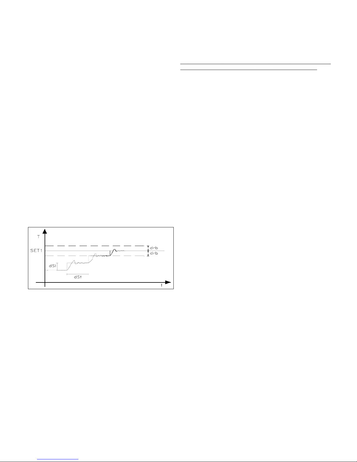
4.4 - FUNZIONE SET POINT DINAMICO
La funzione Set Point Dinamico agisce solo sull'uscita OUT 1 ed è
utilizzabile per prevenire sovraelongazioni iniziali eccessive del valore di
processo a causa dell'inerzia del sistema o quando si desidera un graduale
raggiungimento del valore di Set. Tramite questa funzione si ottiene
automaticamente un aumento progressivo nel tempo del Set Point di
regolazione dal valore di processo all'accensione dello strumento al valore
di Set impostato.
I parametri da impostare per tale funzione sono:
"drb" : Semibanda simmetrica a cavallo del Set Point al di fuori della
quale è attivata la funzione di Set Point Dinamico.
"dSI" : Valore di incremento del Set tra due istanti successivi stabiliti.
"dSt" : Tempo che deve intercorrere tra due successivi incrementi di Set
Point.
La funzione di Set Point Dinamico viene disabilitata impostando dSi = 0.
5 - PROGRAMMAZIONE
5.1 - IMPOSTAZIONE DEI SET POINT
Premere il tasto P quindi rilasciarlo, il led OUT1 lampeggierà e il display
visualizzerà il SET1 impostato. Per modificarlo agire sui tasti UP per
incrementare il valore o DOWN per decrementarlo. Questi tasti agiscono a
passi di un digit ma se mantenuti premuti oltre un secondo il valore si
incrementa o decrementa in modo veloce, e dopo due secondi nella stessa
condizione la velocità aumenta ulteriormente per consentire il rapido
raggiungimento del valore desiderato. Premendo ancora il tasto P e
rilasciandolo il led OUT2 lampeggierà e verrà visualizzato il SET2
impostato che potrà essere modificato agendo sui tasti UP e DOWN come
già descritto. L'uscita dal modo di impostazione del set avviene
automaticamente non agendo su alcun tasto per circa 5 secondi, a quel
punto il display tornerà a visualizzare il valore di processo.
5.2 - PROGRAMMAZIONE DEI PARAMETRI
Per avere accesso ai parametri di funzionamento dello strumento occorre
premere il tasto P e mantenerlo premuto per circa 5 secondi, trascorsi i
quali il led OUT1 lampeggierà e il display visualizzerà il codice che
identifica il primo parametro. A questo punto è possibile rilasciare il tasto
P e agendo sui tasti UP o DOWN selezionare il parametro desiderato. Una
volta selezionato il parametro sul quale si intende operare premere il tasto
P e mantenerlo premuto, verrà quindi visualizzato il valore impostato. Per
modificare tale valore mantenere sempre premuto il tasto P e agire
contemporaneamente sui tasti UP o DOWN. Una volta impostato il valore
desiderato rilasciare il tasto P e il display mostrerà nuovamente la sigla del
parametro selezionato. Agendo sui tasti UP o DOWN è quindi possibile
selezionarne un altro e modificarlo come descritto. Per uscire dal modo di
programmazione non agire su alcun tasto per circa 20 secondi, lo strumento
si riporterà automaticamente al modo di funzionamento normale
visualizzando il valore di processo.
TECNOLOGIC - THP 24 USER MANUAL (I - GB) - Vr. 01 - ISTR 00239 - PAG. 3
Page 4

Attendere sempre l'uscita dalla fase di programmazione poichè se lo
strumento viene spento prima dell'uscita tutti i dati inseriti durante l'ultima
sessione non saranno memorizzati.
5.3 - IMPOSTAZIONE DEI LIMITI DI INGRESSO
Se lo strumento è predisposto con ingresso per segnali normalizzati 4..20
mA, 0..20 mA o 0..10 V è necessario impostare i limiti di ingresso per la
corretta visualizzazione della misura. Ad esempio se la sonda da collegare
ha un range 0..100 bar sarà necessario impostare 0 come al parametro
"Lci" ( riferimento minimo o inizio scala) e 100 al parametro "Hci"
(riferimento massimo o fine scala). Analogamente se si decide di avere una
visualizzazione con punto decimale occorrerà modificare detti parametri.
Ad esempio se lo strumento è collegato ad una sonda di umidità con un
range 20..99 %RH e si decide di visualizzare la grandezza con il punto
decimale occorrerà prima impostare il par. "dP" come "on" e
successivamente i parametri "Lci" a 20.0 e "Hci" a 99.9.
6 - DESCRIZIONE DEI PARAMETRI
Di seguito vengono descritti tutti i parametri di cui lo strumento può essere
dotato, si fa presente che alcuni di essi potranno non essere presenti o
perchè dipendono dal tipo di strumento utilizzato o perchè sono
automaticamente disabilitati in quanto parametri non necessari.
d1- DIFFERENZIALE DI INTERVENTO 1: Valore tra attivazione e
disattivazione rispetto al Set1 dell'uscita OUT1.
d2- DIFFERENZIALE DI INTERVENTO 2: Valore tra attivazione e
disattivazione rispetto al Set2 dell'uscita OUT2.
db - ZONA NEUTRA: Valore che rappresenta la semibanda della Zona
Neutra posta a cavallo del Set1 nel modo di funzionamento omonimo.
LS1 - SET MINIMO 1: Valore minimo impostabile come Set1 o limite
inferiore del Set1.
LS2 - SET MINIMO 2: Valore minimo impostabile come Set2 o limite
inferiore del Set2.
HS1 - SET MASSIMO 1: Valore massimo impostabile come Set1 o limite
superiore del Set1.
HS2 - SET MASSIMO 2: Valore massimo impostabile come Set2 o limite
superiore del Set2.
Pb - BANDA PROPORZIONALE: Ampiezza della banda intorno al Set1
nella quale interviene la regolazione proporzionale.
It - TEMPO INTEGRALE: Tempo integrale da impostare nell'algoritmo di
regolazione PID.
dt - TEMPO DERIVATIVO: Tempo derivativo da impostare nell'algoritmo
di regolazione PID.
rSt - RESET MANUALE: Valore di Offset per la banda proporzionale.
od - RITARDO USCITE: Ritardo da quando la regolazione richiede una
variazione dello stato delle uscite a quando questo avviene realmente, sia
per l'attivazione che per la disattivazione (in sec.). Il ritardo non è operante
sull'uscita OUT 1 nel modo di regolazione PID.
Ct - TEMPO DI CICLO : Tempo di ciclo per l'uscita OUT1 quando
interviene la regolazione proporzionale nel modo di regolazione PID.
drb - BANDA RESTART SET DINAMICO: Semibanda simmetrica a
cavallo del Set che stabilisce la zona al di fuori della quale interviene il
funzionamento del Set dinamico.
dSI - INCREMENTO SET DINAMICO: Valore di incremento del Set
point dinamico tra due istanti successivi stabiliti dal par. "dSt".
dSt - INTERVALLO INCREMENTO SET DINAMICO: Intervallo di
tempo tra un incremento del Set dinamico e il successivo (in sec.).
Lci - LIMITE INFERIORE INGRESSO PER SEGNALI
NORMALIZZATI : Valore che lo strumento deve visualizzare quando al
circuito di ingresso è presente il valore minimo (4 mA, 0 mA, 0 V).
Hci - LIMITE SUPERIORE INGRESSO PER SEGNALI
NORMALIZZATI:Valore che lo strumento deve visualizzare quando al
circuito di ingresso è presente il valore massimo (20 mA, 10 V).
CAL - CALIBRAZIONE: Offset positivo o negativo che viene sommato al
valore letto dalla sonda prima della visualizzazione alla quale è legato
anche il funzionamento di regolazione. Questo parametro può rendersi
necessario per una ritaratura dello strumento.
Ft - TIPO DI REGOLAZIONE: Permette di selezionare uno dei possibili
modi di regolazione che lo strumento offre: ON/OFF (on), PID (Pi) o Zona
Neutra (nr).
PSE - SONDA IN INGRESSO: Permette di selezionare, se il modello dello
strumento è per termocoppie o per termoresistenze, vari eventuali tipi di
sonda in ingresso: per termocoppie J (FE), K (Cr) , S (rh) e per
termoresistenze Pt100 (Pt), Ni100 (ni). Al cambio di questo parametro si
raccomanda di attendere l'uscita dalla fase di progammazione e quindi di
spegnere e riaccendere lo strumento.
OCO - LEGAME SET: Permette di stabilire se i due Set devono essere
indipendenti o se il Set2 deve essere considerato relativo al Set1
(in=indipendenti, di=dipendenti).
HC1 - MODO DI FUNZIONAMENTO USCITA 1: Stabilisce se l'uscita
OUT1 deve funzionare con azione inversa (es. Riscaldamento,
Umidificazione ecc.) oppure con azione diretta ( es. Refrigerazione,
Deumidificazione ecc.) (H=inversa, C=diretta).
HC2 - MODO DI FUNZIONAMENTO USCITA 2: Stabilisce se l'uscita
OUT2 deve funzionare con azione inversa (es. Riscaldamento,
Umidificazione ecc.) oppure con azione diretta ( es. Refrigerazione,
Deumidificazione ecc.) (H =inversa, C=diretta).
dP - PUNTO DECIMALE: Permette di inserire il punto decimale nella
visualizzazione e quindi di stabilire la risoluzione del display (1 o 0,1) ma
non il Set, i limiti del Set (par. "LS", "HS") e i limiti di ingresso (par. "Lci",
"Hci") che devono essere modificati manualmente. Per esempio se il Set era
20 e viene inserito il punto decimale il Set sarà 2.0 (on= con punto
decimale, oF=senza punto decimale). (disponibile solo nei modelli con
ingresso PTC, RTD o per segnali normalizzati)
rou - UNITA' DI MISURA: Stabilisce, per misure di temperatura, la
visualizzazione in gradi Centigradi o Fahrenheit. Si fa presente che la
modifica di questo parametro modifica la visualizzazione del display ma
non il Set ed i limiti del Set (per. "LS" e "HS") impostati, che devono
essere modificati manualmente. Ad esempio se il Set era 50 °C e viene
cambiata l'unità di misura il Set sarà 50 °F.
tun - AUTOTUNING: Parametro di selezione per effettuare un ciclo di
Autotuning, che permette il calcolo automatico dei parametri di regolazione
PID (n=no autotuning, y=start autotuning).
hdd - APPROSSIMAZIONE ULTIMA CIFRA: Permette
l'approssimazione della cifra meno significativa. In quest'ultima infatti, se
inserita la funzione, verrà visualizzato 0 se il valore effettivo è compreso tra
0 e 4, oppure 5 se il valore è compreso tra 5 e 9. Ad esempio se la funzione
è inserita e la misura fatta dallo strumento risulta essere 78 il display
visualizzerà 75, oppure se la misura è 70.3 il display visualizzerà 70.0
(n=senza approssimazione, y=con approssimazione).
tAb - PARAMETRO NON MODIFICABILE
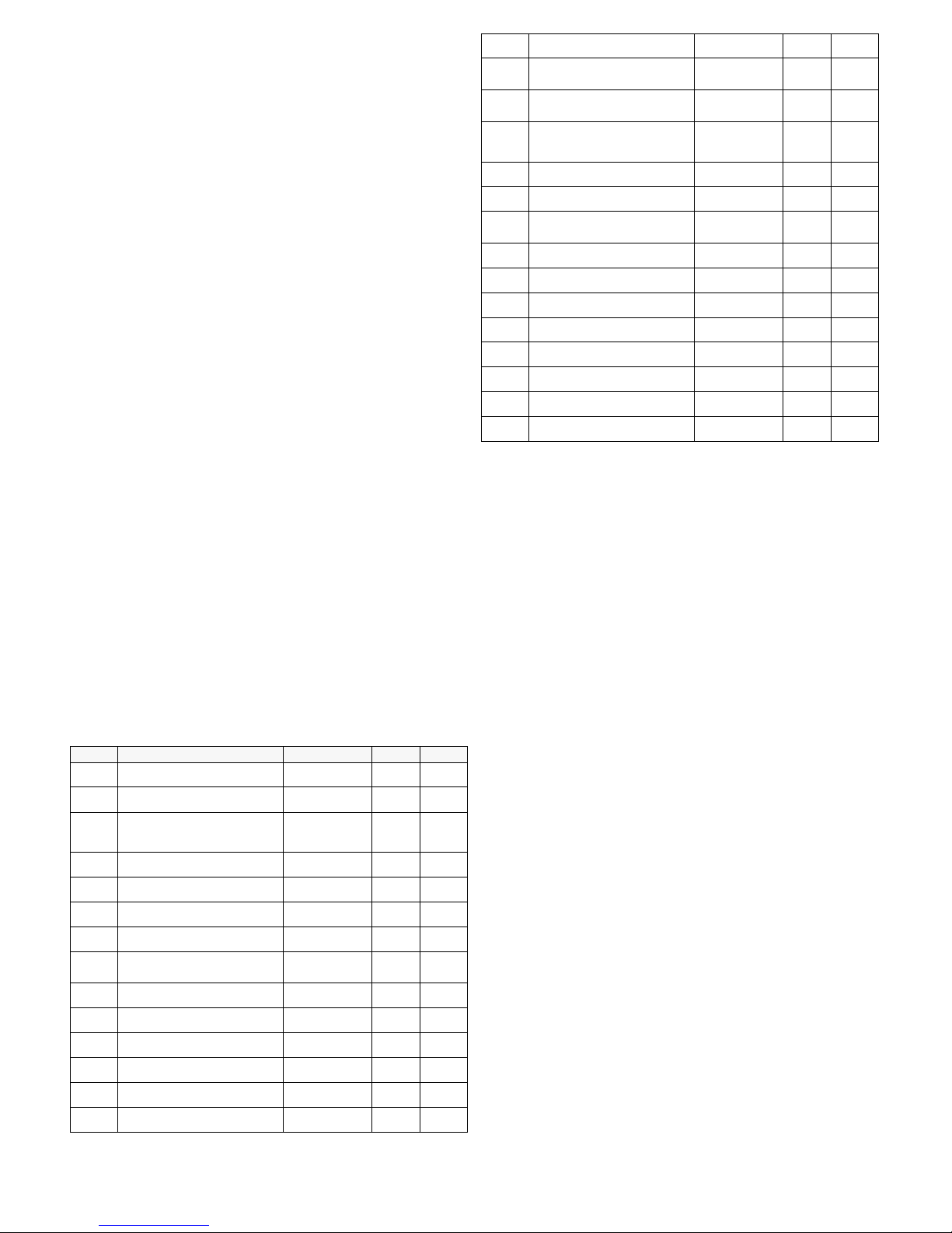
6.1 - TABELLA PARAMETRI
-99-999 ... 7000Limite inferiore ingresso
per segnali normalizzati
Lci
11 ... 3600 sec.Intervallo incremento Set
Dinamico
dSt
00 ... Probe limitIncremento Set Dinamico
dSI
00 ... Probe limitBanda restart Set Dinamico
drb
201 ... 500 sec.Tempo di ciclo
Ct
00 ... 500 sec.Ritardo uscite
od
0Probe limitReset manuale
rSt
300 ...3600 sec.Tempo derivativo
dt
3000 ...3600 sec.Tempo integrale
It
401/0,1 ... Probe
limit
Banda proporzionale
Pb
Max. Probe limitSet massimo 2
HS2
Max. Probe limitSet massimo 1
HS1
min. Probe limitSet minimo 2
LS2
min. Probe limitSet minimo 1
LS1
11/0,1 ... Probe
limit
Zona neutra
db
-1Probe limitDifferenziale 2
d2
-1Probe limitDifferenziale 1
d1
NoteDef.RangeDescrizionePar.
TECNOLOGIC - THP 24 USER MANUAL (I - GB) - Vr. 01 - ISTR 00239 - PAG. 4
Page 5
------Parametro non modificabile
tAb
ny - nApprossimazione ultima
cifra
hdd
ny - nAutotuning
tun
°C°C - °FUnità di misura
rou
oFon - oFPunto decimale
dP
HH - CModo di funzionamento
uscita OUT2
HC2
HH - CModo di funzionamento
uscita OUT1
HC1
indi - in Legame set
OCO
Tc: FE
Rtd: Pt
Tc: FE - Cr - rh
Rtd: Pt - Ni
Sonda in ingresso
PSE
Pion - Pi - nrTipo di regolazione
Ft
0-999 ... +999Calibrazione
CAL
999-999 ... 7000Limite superiore ingresso
per segnali normalizzati
Hci
7 - PROBLEMI, MANUTENZIONE E GARANZIA
SEGNALAZIONI DI ERRORE: Lo strumento prevede la visualizzazione
dei messaggi di errore sonda "EEEE" , in caso la sonda sia interrotta o in
overrange, oppure "- - - -" nel caso la sonda (PTC, RTD o per segnali
normalizzati) sia in cortocircuito o in underrange, in tal caso verificare la
corretta connessione della sonda con lo strumento e successivamente
procedere alla verifica della stessa. Nelle condizioni di errore tutte le uscite
sono disattivate.
PULIZIA: Si raccomanda di evitare l'utilizzo di detergenti abrasivi o
contenenti solventi che possono danneggiare lo strumento.
GARANZIA E RIPARAZIONI: Lo strumento è garantito da vizi di
costruzione o difetti di materiale riscontrati entro i 12 mesi dalla data di
consegna. La garanzia si limita alla riparazione o la sostituzione del
prodotto. L'eventuale apertura del contenitore, la manomissione dello
strumento o l'uso e l'installazione non conforme del prodotto comporta
automaticamente il decadimento della garanzia. In caso di prodotto
difettoso in periodo di garanzia o fuori periodo di garanzia contattare
l'ufficio vendite TECNOLOGIC per ottenere l'autorizzazione alla
spedizione. Il prodotto difettoso, quindi , accompagnato dalle indicazioni
del difetto riscontrato, deve pervenire con spedizione in porto franco presso
lo stabilimento TECNOLOGIC salvo accordi diversi.
1 - GENERAL DESCRIPTION
THP 24 is a digital microprocessor based controller with 1 or 2 set point,
ON/OFF, PID or NEUTRAL ZONE mode and with AUTOTUNING
function for PID mode. The process value is visualised on 4 red displays
and the outputs state is indicated by 2 leds. The instrument has up to 2
outputs 1 relay and 1 for solid state relay (SSR) driving and 1 input for
PTC (KTY 81), or RTD (Pt 100 or NI100), or Thermocouple (J-K-S)
temperature probes or for any kind of probe having normalised output in
current (4..20 mA, 0..20 mA) or voltage (0..10 V).
1.1 - FRONT PANEL
1 - Key P : Used for the set point setting and to program the functioning
parameters
2 - Key DOWN : Used to decrease the values or to select parameters
3 - Key UP : Used to increase the values or to select parameters
4 - Led OUT1 : Signalize when the output OUT1 is on (on) or off (off) and
signalize the set point 1 or the parameters programming mode (flashing)
5 - Led OUT2 : Signalize when the output OUT2 is on (on) or off (off) and
signalize the set point 2 programming mode (flashing)
1.2 - INSTRUMENT CODE
THP 24 a b cc dd
a =
SUPPLY
L : 24 VAC/VDC
H : 90 ... 240 VAC
c = INPUT
C : Termocouples (J, K, S)
D : Termoresistances (Pt100, Ni100 IEC)
E : Termistors PTC (KTY 81)
F : Normalized signals 4..20 mA
A : Normalized signals 0..20 mA
V : Normalized signals 0..10 V
cc =
OUTPUTS
OR : OUT1 Voltage output 6 VDC for SSR, OUT2 Relay
RO : OUT1 Relay, OUT2 Voltage output 6 VDC for SSR
O- : OUT1 Voltage output 6 VDC for SSR, OUT2 not present
R- : OUT1 Relay, OUT2 not present
dd
= SPECIAL CODES
2 - TECHNICAL DATA
ELECTRICAL DATA
Supply:
24 VAC/VDC, 90 ... 240 VAC +/- 10%
Frequency
AC: 50/60 Hz
Power
consumption: 3 VA approx.
Input/s:
1 input. For temperature probes tc J, K, S or RTD Pt 100 IEC, Ni
100 or PTC (KTY 81-121 990
Ω
at 25 °C) or for normalized signals 4..20
mA, 0..20 mA o 0..10 V
Output/s:
Up to 2 outputs. 1 Relay (5A-AC1, 2A-AC3 250 VAC) ; 1 voltage
for SSR drive (6 VDC/15 mA)
Electrical
life for relay output: 100000 operat.
Protection
class against electric shock: Class II for Front panel
Insulation:
Reinforced insulation between the low voltage section (supply
and relay outputs) and the front panel; Basic insulation between the low
voltage section (supply and relay outputs) and the extra low voltage section
(input and output for SSR); No insulation between input and output for
SSR driving
MECHANICAL DATA
Housing:
Self-extinguishing plastic, UL 94 V0
Dimensions:
24 x 48 mm DIN, depht 100 mm
Weight:
80 g approx.
Mounting:
Flush in panel in 22 x 45 mm hole
Connections:
extractable 2,5 mm2 screw terminal block
Degree
of protection of front panel : IP 54 mounted in panel with gasket
Pollution
situation: Normal
Operating
temperature: 0 ... 55 °C
Operating
humidity: 30 ... 95 RH% without condesation
Storage
temperature: -10 ... +60 °C
FUNCTIONAL DATA
Control:
ON/OFF, NEUTRAL ZONE, PID
Measurement
range: according to the used probe (see table range)
Display
resolution: according to the probe used 1/0,1/5/0,5
TECNOLOGIC - THP 24 USER MANUAL (I - GB) - Vr. 01 - ISTR 00239 - PAG. 5
Page 6
Overall accuracy: +/- 0,5 % fs
Sampling
rate: 1 sample per second
Action:
1C type according to EN 60730-1
Compliance:
ECC directive EMC 89/336 (EN 50081-1, EN 50082-1), ECC
directive LV 73/23 and 93/68 (EN 60730-1)
MEASUREMENT RANGE TABLE
-99.9 ... 700.0- 999 ... 7000
4..20 mA, 0..20 mA,
0..10 V (gener.)
---0 ... +1600 °C
+32 ... +2912 °F
tc S (rh)
---0 ... +1200 °C
+32 ... +2192 °F
tc K (Cr)
---0 ... +800 °C
+32 ... 1472 °F
tc J (FE)
-50.0 ... +150.0 °C
-58.0 ... +302.0 °F
-50 ... +150 °C
-58 ... +302 °F
Ni 100 (ni)
-99.9 ... +600.0 °C
-99.9 ... +999.9 °F
-100 ... +600 °C
-148 ... +1112 °F
Pt 100 (Pt)
-50.0 ... +150.0 °C
-58.0 ... +302.0 °F
-50 ... +150 °C
-58 ... +302 °F
PTC
4 DIGIT with D.P.4 DIGIT PROBE
3 - INSTALLATION
MECHANICAL MOUNTING: The instrument, in DIN case 24 x 48 mm,
is designed for panel mounting. Make an hole 22 x 45 mm and insert the
instrument, fixing it with the provided special brackets .We recommend to
mount the gasket to obtain an IP 54 front protection. Avoid to place the
instrument in areas with humidity or dirt. Connect the instrument as far as
possible from source of electromagnetic disturbances so as motors, power
relays, relays, electrovalves,etc.
ELECTRICAL CONNECTIONS: Carry out the electrical wiring
connecting only one wire for each terminal , according to the following
diagram, check that the power supply is the same as indicated on the
instrument and the loads current is not upper than the maximum current
admitted. The instrument, being a built in equipment with permanent
connection into a cabinet, is not furnished with internal device protecting
from overcurrent : it's recommended , therefore, to properly protect all the
electric circuits connected to the instrument, with devices (ex. fuses)
proportionate to the circulating currents. It's strongly recommended to use
cables with proper insulation, according to the working voltages and
temperatures. Furthermore, the input cable of the probe has to be kept
separate from line voltage wiring. If the input cable of the probe is
screened, it has to be connected on the ground with only one side. It is
advisable to check that the parameters are those desired before connecting
the outputs to the actuators so as to avoid malfunctioning . Whenever a
failure of the instrument could cause dangerous or damaging situations, it
should be kept in mind that the plant has to be provided with additional
devices to ensure the safety.
4 - OPERATING MODE
4.1 - ON/OFF CONTROL
The control mode of the instrument by ON/OFF mode occours on the
outputs according to the Sets point fixed, to the differential switching
points (par. "d1", "d2") and to operating modes (par. "HC1", "HC2")
programmed. For a correct functioning it is necessary to set a negative
differential switching point for reverse controls (ex.Heating processes) and
a positive differential switching point for direct controls (ex.Cooling
processes). Furtheremore the two Sets can be programmed independently
or dependently throught the parameter Sets Connection ("OCO"), and in
the case of set dependentlythe real regulation Set of output 2 will be
[Set1+Set2]. If output 2 is used as an alarm output, par. "OCO"
determines if the alarm is absolute or relative (in=absolute, di=relative)
and par. "HC2" determines if the alarm is low or high (H=low, C=high).
The operating mode can be also modified by means of outputs delay
parameter (par. "od") or Dynamic Set Point function, see the next
chapters for these functions.
4.2 - NEUTRAL ZONE CONTROL
The Neutral Zone control mode concerns both outputs and is generally
necessary for controllig a plant that possesses an Positive regulation
element (ex. Heating, Humidification etc.) and a Negative regulation
element (ex. Cooling, Dehumidification etc.) . The functioning is
determined by the Set1 (Set2 is automatically disconnected) and Neutral
Zone (par. "db"). Subsequently the regulator operates as follows: switches
off the outputs when the process value is the same as Set, switch on the
output OUT1 when the process value is under as [Set1-db], and switch on
the output OUT2 when the process value is upper as [Set1+db]. Thus the
Positive regulation element will be connected to output OUT1, while the
Negative regulation element is at output OUT2.
4.3 - PID CONTROL AND AUTOTUNING FUNCTION
PID control mode can only be carried out through output OUT 1 while
output OUT 2 can only operates by means of ON/OFF control mode with
Set 2 independent or dependended in respect with Set 1 and can therefore
be used as an alarm (see ON/OFF regulator). The PID algorithm of the
instrument is provided to program the following parameters:
For
PROPORTIONAL term :
"Pb" - Proportional Band,
"rst" - Manual reset
"Ct" - Cycle time.
For
INTEGRAL term:
"It" - Integral time
For
DERIVATIVE term:
"dt" - Derivative time
The instrument is set on parameters relative to PID control of standard
value. If ever these should result to be unsuitable it would be advisable to
TECNOLOGIC - THP 24 USER MANUAL (I - GB) - Vr. 01 - ISTR 00239 - PAG. 6
Page 7
program the AUTOTUNING function. The Autotuning function permits the
automatic tuning of the PID instrument parameters.
To active the AUTOTUNING function proceed as follows :
- Set the desired "Set point".
- Set the desired parameters and especially "HC1".
- Set the parameter "Ft": Pi
- Connect the instrument with the plant
- Set the parameter "tun" : y
- Wait for the outing from the programmation
Now, the Autotuning function is activated and it's shown by the flashing of
the process value on the display. The regulator automatically tunes all the
right parameters for a correct PID control mode. Before to switch off the
instrument always wait for the end of the Autotuning process, indicated by
the return of the display on the normal functioning, . The Autotuning
procedure has been limited at a maximum time of 4 hours, after this time, if
the Autotuning is not completed the instrument automatically get out from
the procedure, showing constantly on the display the "EEE" indication. To
stop the Autotuning cycle or re-establish the normal functioning after an
error, switch off and on the instrument. The calculated values will be
automatically memorised by the instrument at the end of the Autotuning
cycle, in the PID control parameters.
4.4 - DYNAMIC SET POINT FUNCTION
This function is only obtainable throught output OUT 1 and is usefull to
avoid starting over-extention of the process value caused by the inertness
of the system or when is wished a gradual reaching of Set value. Infact by
means of this function an automatic increase in the time of the regulation
Set from the power on-process value to the programmed Set is obtained.
The parameters to be programmed for this function are:
"drb" : Symmetrical semi-band over-lapping the Set outside from which
the function is activated.
"dSI" : Increment value of dynamic Set between two successive increments
of the dynamic Set value.
"dSt" : Time lapse between two successive increments of the dynamic Set
value.
The Dynamic Set Point function is automatically disconnected by setting
dSi = 0.
5 - PROGRAMMING
5.1 - PROGRAMMING OF SET-POINTS
Press key P then release it, led OUT1 will flash and the SET1 value will be
shown on display. To modify press key UP so as to increase value or
DOWN so as to decrease it. These keys count one digit at a time but if the
keys are pressed for over one second the value increases or decreases fast
and after two seconds the speed increases even more, so as to reach the
desired value immediately. Pressing key P again and releasing it, led
OUT2 will flash and SET2 which was previously set, will be displayed, it
can be modified by pressing keys UP or DOWN as already mentioned. The
outgoing from the Set programming mode occurs automatically by not
pressing any key for about 5 seconds, thus the process value will again be
displayed.
5.2 - PROGRAMMING OF PARAMETERS
To accede to the operating parameters it is necessary to press key P
holding it down for about 5 seconds, afterwhich the led OUT1 will flash
and the code of the first parameter will be visualized on the display. At this
point key P can be released and by pressing UP or DOWN the desired
parameter can be selected. Once the parameter on which we intended to
operate has been selected to modify it press P, while holding it down, the
set of the parameter will show up. To modify this value keep P pressed
while acting on UP or on DOWN so as to increase or decrease the value.
Once the desired value has been set release P and the selected parameter
code can be read on the display. By pressing UP or DOWN it is therefore
possible to choose another one and modify it as previously mentioned. To
outgoing from the programming mode no key is to be pressed for about 20
seconds, the instrument will automatically return to normal functioning
mode, visualizing the process value.
The
instrument must not to be switched off during the programming mode
otherwise the data inserted in the last session will not be memorized.
5.3 - PROGRAMMING OF INPUT LIMITS
If the instrument is provided with input for normalized signals 4..20 mA,
0..20 mA or 0..10 V it is necessary to set input limits to have the correct
measure indication. For example: if the probe to connect has a range of
0..100 bar, it will be necessary to program 0 on "Lci" parameter (start
scale) and 100 on "Hci" parameter (end scale). At same time, we have to
modify the same parameters to have the decimal point. Example:
instrument connected with relative humidity probe with 20..99 %RH as
range, to have the decimal point it will occour to program "dP" in "on"
mode, "Lci" at 20.0 and "Hci" at 99.9.
6 - DESCRIPTION OF PARAMETERS
Here following are described all the instrument parameters; pls. note that
some of them could do not appear or because are according to the kind of
used instrument or because are automatically not qualified, as they're not
necessary.
d1 - DIFFERENTIAL SWITCHING POINT1: Value between starting and
stopping of output OUT1.
d2 - DIFFERENTIAL SWITCHING POINT2: Value between starting and
stopping of output OUT2.
db - NEUTRAL ZONE : Value which represents the semi-band of the
Neutral Zone, in the homonymous functioning mode, overlapping Set1.
LS1 - MINIMUM SET1: Minimum possible Set point 1 value or lower
limit of Set point 1.
LS2 - MINIMUM SET2: Minimum possible Set point 2 value or lower
limit of Set point 2.
HS1 - MAXIMUM SET1: Maximum possible Set point1 value or higher
limit of Set point1.
HS2 - MAXIMUM SET2: Maximum possible Set point2 value or higher
limit of Set point2.
Pb - PROPORTIONAL BAND : Amplitude of the band around Set 1 in
which proportional control takes place.
It - INTEGRAL TIME : Integral time to be set in algorithm of PID control
mode.
dt - DERIVATIVE TIME: Derivative time to set in algorithm of PID control
mode.
rSt - MANUAL RESET : Offset value for proportional band.
od - OUTPUTs DELAY: Delay from when the control need a variation to
the condition of the outputs to when this actually happens (expr. in sec.).
Non operating on output Out 1 in PID control mode.
Ct - CYCLE TIME: Cycle time of OUT 1 when proportional control takes
place in PID control mode.
drb - RESTART BAND DYNAMIC SET: Semiband found in the symmetrical zone in respect with Set outside of which intervenes the functioning of
the Dynamic Set Point.
dSI - DYNAMIC SET INCREMENT: Increment value of dynamic Set Point
function between two successive instant determines by the par. dSt.
dSt - DYNAMIC SET INCREMENT INTERVAL: Interval between one
Dynamic Set Point increment and the next (expr. in sec.).
Lci - LOWER NORMALIZED SIGNALS INPUT LIMIT: Value that the
instrument must to indicate in correspondance of minumum value (4 mA, 0
mA, 0 V).
Hci - HIGHER NORMALIZED SIGNALS INPUT LIMIT: Value that the
instrument must to indicate in correspondance of maximum value (20 mA,
10 V).
CAL - CALIBRATION: Positive or negative offset which is calculated on
probe reading before visualizing and to which the control functioning is
also connected. This parameter can be utilized when a recalibration of the
instrument is desired.
TECNOLOGIC - THP 24 USER MANUAL (I - GB) - Vr. 01 - ISTR 00239 - PAG. 7
Page 8
Ft - CONTROL MODE: Allows the selection of one of possible control
modes that the instrument offers: ON/OFF (on), PID (Pi) or Neutral Zone
(nr).
PSE - INPUT PROBE: Allows selecting, if the instrument type is for
thermocouples or for thermoresistances, various types of probe: J (FE), K
(Cr), S (rh) for thermocouples and Pt100 (Pt), Ni100 (ni) for
thermoresistances. On changing this parameter it is to be remember that
the exit programming phase is to be carried out first afterwhich the
instrument is to be switched off and then on again.
OCO - SETS CONNECTION: Determines if the two Sets are to be
independent or if Set2 must be considered relative to Set1 (in=independent,
di=dependent).
HC1 - OUTPUT 1 OPERATING MODE: Determines if the output OUT1 is
tocontrol a process which increment is intended as positive or reverse (ex.
Heating, Humidification etc.) or a process which increment is intended as
negative or direct (ex. Cooling, Dehumidification etc.) (H=reverse ,
C=direct).
HC2 - OUTPUT 2 OPERATING MODE: Determines if the output OUT2 is
to control a process which increment is intended as positive or reverse (ex.
Heating, Humidification etc.) or a process which increment is intended as
negative or direct (ex. Cooling, Dehumidification etc.) (H=reverse ,
C=direct).
dP - DECIMAL POINT : Allows the insertion of the decimal point on the
display and therefore to determine resolution of the reading value (1 or
0,1) but not modified the Set, the Set limits (par. "LS", "HS") and the input
limits (par. "Lci", "Hci"). Example, if the Set was 20 the new Set will be 2.0
(on= with decimal point, oF=without decimal point).(available only for
models provided for PTC, RTD and normalized signals input).
rou - UNIT OF MEASUREMENT: Determines the visualization of the
temperature in Centigrade or Fahrenheit degree. It is to be remember that
the change of this parameter modifies the visualization but not the Set and
the Set limit ("LS" and "HS") programmed (eg. if the Set was 50°C and the
unit changes, the Set will rest 50°F).
tun - AUTOTUNING: Determines the selection of Autotuning function for
the automatic setting of PID parameters (n=no autotuning, y=start
autotuning).
hdd - HALF DIGIT DISPLAY: This parameter allows the approximation of
the last digit at right side. Infact when this parameter is in on mode, on this
digit will be show 0 when the real measuring value is between 0 and 4, and
will be show 5 when the real measuring value is between 5 and 9. For
example if the real measure is 78 display will show 75, or if the real
measure is 70.3 the display will show 70.0 (n=without approximation,
y=with approximation).
tAb - FIXED PARAMETER
6.1 - PARAMETERS TABLE
00 ... Probe limitRestart band Dynamic Set
drb
201 ... 500 sec.Cycle time
Ct
00 ... 500 sec.Outputs delay
od
0Probe limitManual reset
rSt
300 ...3600 sec.Derivative time
dt
3000 ...3600 sec.Integral time
It
401/0,1 ... Probe
limit
Proportional band
Pb
Max. Probe limitHigh/Maximum set 2
HS2
Max. Probe limitHigh/Maximum set 1
HS1
min. Probe limitLow/minimum set 2
LS2
min. Probe limitLow/minimum set 1
LS1
11/0,1 ... Probe
limit
Neutral zone
db
-1Probe limitDifferential 2
d2
-1Probe limitDifferential 1
d1
NotesDef.RangeDescriptionPar.
------Fixed parameter
tAb
ny - nHalf digit display
hdd
ny - nAutotuning
tun
°C°C - °FUnit of measurement
rou
oFon - oFDecimal point
dP
HH - COutput 2 operating mode
HC2
HH - COutput 1 operating mode
HC1
indi - in Sets connection
OCO
Tc: FE
Rtd: Pt
Tc: FE - Cr - rh
Rtd: Pt - Ni
Input probe
PSE
Pion - Pi - nrControl mode
Ft
0-999 ... +999Calibration
CAL
999-999 ... 7000Higher limit for normalized
signal input
Hci
-99-999 ... 7000Lower limit for normalized
signal input
Lci
11 ... 3600 sec.Dynamic Set increment
interval
dSt
00 ... Probe limitDynamic Set increment
dSI
7 - PROBLEMS, MAINTENANCE AND WARRANTY
ERRORS SIGNALLING: The instrument shows the error message
"EEEE" , when the probe is interrupted or in overrange, or "- - - -"
when the probe (PTC, RTD or normalised signals) is in short-circuit or
underrange; in this case verify the correct probe wiring with the
instrument and afterward proceed to verify itself. In the error condition all
the outputs are disactivated.
HOW TO CLEAN: We recommend to avoid abrasive cleaners or
containing solvents which could damage the instrument.
WARRANTY AND REPAIRS: The instrument is under warranty against
construction vices or defected material, noticed within 12 months from
delivery date.The warranty is limited to the repairs or to the substitution of
the instrument. The eventual opening of the housing, the violation of the
instrument or the wrong use and installation of the product means the
automatically decay of the warranty. In case of defected instrument,
noticed in warranty period or out of warranty, do contact our sales
department to obtain the shipment authorisation. The defected product
must be shipped to TECNOLOGIC with the detailed description of the
failures found and without any fees or charge for Tecnologic, safe
different agreements.
TECNOLOGIC - THP 24 USER MANUAL (I - GB) - Vr. 01 - ISTR 00239 - PAG. 8
 Loading...